1
Online Help
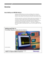
ArbExpress® AXW100
Waveform Creation and Editing Tool
for Tektronix AWG/AFG Version 2.3
077-0000-03
Adapted from the ArbExpress Online Help, Version 2.3.
www.tektronix.com
Copyright © Tektronix, Inc. All rights reserved. Licensed software products are owned by Tektronix or
its suppliers and are protected by United States copyright laws and international treaty provisions.
Tektronix products are covered by U.S. and foreign patents, issued and pending. Information in this
publication supercedes that in all previously published material. Specifications and price change
privileges reserved.
TEKTRONIX, TEK, and ARBEXPRESS are registered trademarks of Tektronix, Inc.
Windows, Windows 98, Windows NT, Windows 2000, Windows XP Professional and Windows Me are
trademarks of Microsoft Corporation.
®
ArbExpress AXW100 Waveform Creation and Editing Tool for Tektronix AWG/AFG version 2.3.
Contacting Tektronix
Tektronix, Inc.
14200 SW Karl Braun Drive or P.O. Box 500
Beaverton, OR 97077 USA
For product information, sales, service, and technical support:
In North America, call 1-800-833-9200.
Worldwide, visit www.tektronix.com to find contacts in your area.
Table of Contents
OVERVIEW ......................................................................................................................1
About ArbExpress AXW100 Software............................................................................................ 1
Configuration ................................................................................................................................... 2
Installation ....................................................................................................................................... 2
Using Online Help ........................................................................................................................... 4
Printing from the Online Help ......................................................................................................... 5
GETTING STARTED.......................................................................................................7
Basic Operations .............................................................................................................................. 7
File Name Extensions ...................................................................................................................... 9
Application File Names and Directories.......................................................................................... 9
Starting the Application ................................................................................................................. 10
Opening a Waveform..................................................................................................................... 10
Creating a Waveform..................................................................................................................... 11
Saving a Waveform ....................................................................................................................... 12
Closing a Waveform ...................................................................................................................... 12
Exiting the Application .................................................................................................................. 13
Shortcut Keys................................................................................................................................. 13
OPERATING BASICS ...................................................................................................15
Menus ............................................................................................................................................ 15
File Menu ................................................................................................................................ 15
Edit Menu................................................................................................................................ 17
View Menu .............................................................................................................................. 18
Display Menu .......................................................................................................................... 19
Waveform Menu ..................................................................................................................... 20
Math Menu .............................................................................................................................. 21
Communication Menu............................................................................................................. 22
Window Menu......................................................................................................................... 22
Help Menu............................................................................................................................... 23
Use Shortcut Menu for Waveforms......................................................................................... 23
Toolbars ......................................................................................................................................... 26
Standard Toolbar ..................................................................................................................... 26
Waveform Toolbar .................................................................................................................. 27
Table of Contents
Zoom Bar................................................................................................................................. 28
Instrument Bar ......................................................................................................................... 28
Point Draw Toolbar ................................................................................................................. 29
Status Bar................................................................................................................................. 29
Shortcut View ................................................................................................................................ 31
New Waveform View.............................................................................................................. 32
Easy Edit.................................................................................................................................. 33
Multi-Waveform Properties..................................................................................................... 34
Import or Transfer Waveform ................................................................................................. 34
Dialog Boxes.................................................................................................................................. 35
Waveform Properties Dialog Box ........................................................................................... 35
Paste Option Dialog Box ......................................................................................................... 37
Shift/Rotate Dialog Box .......................................................................................................... 37
Point Draw Table Dialog Box ................................................................................................. 38
Cursor Position Dialog Box..................................................................................................... 39
Display Properties Dialog Box ................................................................................................ 39
Equation Editor Dialog Box .................................................................................................... 40
Sine Wave Dialog Box ............................................................................................................ 42
Square Wave Dialog Box ........................................................................................................ 44
Triangle Wave Dialog Box...................................................................................................... 46
Pulse Wave Dialog Box........................................................................................................... 48
Noise Wave Dialog Box .......................................................................................................... 50
DC Wave Dialog Box.............................................................................................................. 51
Exponential Rise Wave Dialog Box ........................................................................................ 53
Exponential Decay Wave Dialog Box..................................................................................... 55
Sinc Wave Dialog Box ............................................................................................................ 57
Sweep Wave Dialog Box......................................................................................................... 59
Multi-Tone Wave Dialog Box................................................................................................. 61
Lorentz Wave Dialog Box....................................................................................................... 63
File Transfer and Instrument Control Dialog Box................................................................... 65
Waveform Math Dialog Box ................................................................................................... 66
Filter Setup Dialog Box........................................................................................................... 67
Set IP Address Dialog Box...................................................................................................... 67
Instrument Properties Dialog Box ........................................................................................... 67
Import from Oscilloscope Dialog Box .................................................................................... 67
Set Pattern Dialog Box ............................................................................................................ 69
ii
ArbExpress® AXW100 Waveform Creation and Editing Tool
Table of Contents
HOW TO ... ...................................................................................................................... 71
Create Waveforms ......................................................................................................................... 71
Using the Equation Editor ....................................................................................................... 71
Sine Wave ............................................................................................................................... 75
Square Wave ........................................................................................................................... 78
Triangle Wave ......................................................................................................................... 81
Pulse Wave.............................................................................................................................. 84
Noise Wave ............................................................................................................................. 87
DC Wave ................................................................................................................................. 90
Exponential Rise Wave ........................................................................................................... 92
Exponential Decay Wave ........................................................................................................ 95
Create Advanced Waveforms ........................................................................................................ 98
Sinc Wave ............................................................................................................................... 98
Sweep Wave .......................................................................................................................... 101
Multi-Tone Wave .................................................................................................................. 104
Lorentz Wave ........................................................................................................................ 107
Create Marker Patterns ................................................................................................................ 110
Marker ................................................................................................................................... 110
Edit Markers.......................................................................................................................... 110
Display ......................................................................................................................................... 111
Cursor .................................................................................................................................... 111
Cursor Position...................................................................................................................... 111
Zoom In ................................................................................................................................. 111
Zoom Out .............................................................................................................................. 111
Horizontal Zoom In ............................................................................................................... 112
Fit to Window........................................................................................................................ 112
Crosshair................................................................................................................................ 112
Graticule ................................................................................................................................ 112
Time Scale............................................................................................................................. 113
Properties............................................................................................................................... 113
Edit Waveforms ........................................................................................................................... 114
Undo ...................................................................................................................................... 114
Redo ...................................................................................................................................... 114
Cut ......................................................................................................................................... 114
Copy ...................................................................................................................................... 114
Paste ...................................................................................................................................... 115
ArbExpress® AXW100 Waveform Creation and Editing Tool
iii
Table of Contents
Select All ............................................................................................................................... 116
Copy to System Clipboard..................................................................................................... 116
Copy as Bitmap ..................................................................................................................... 117
Invert...................................................................................................................................... 117
Mirror .................................................................................................................................... 118
Freehand ................................................................................................................................ 118
Horizontal Draw .................................................................................................................... 118
Vertical Draw ........................................................................................................................ 119
Point Draw............................................................................................................................. 119
Use Math ...................................................................................................................................... 122
Addition................................................................................................................................. 122
Subtraction............................................................................................................................. 124
Multiplication ........................................................................................................................ 125
Division ................................................................................................................................. 127
Communicate with Other Instruments ......................................................................................... 129
AWG/AFG File Transfer and Control................................................................................... 129
Transfer Files to an AWG/AFG ............................................................................................ 131
Control an AFG ..................................................................................................................... 134
Control an AWG.................................................................................................................... 135
Import from Oscilloscope...................................................................................................... 137
Send Waveform to Arb.......................................................................................................... 141
Scope Acquisition Wizard ..................................................................................................... 142
Normalize .............................................................................................................................. 149
Use MATLAB Support................................................................................................................ 150
Creating Waveforms using MATLAB .................................................................................. 150
Transferring Files from MATLAB........................................................................................ 151
Controlling the Instrument..................................................................................................... 153
NewSession Command.......................................................................................................... 154
CloseSession Command ........................................................................................................ 155
Write Command .................................................................................................................... 156
Read Command ..................................................................................................................... 156
LoadWfm Command ............................................................................................................. 157
TransferWfm Command........................................................................................................ 157
Query Command ................................................................................................................... 158
iv
ArbExpress® AXW100 Waveform Creation and Editing Tool
Table of Contents
REFERENCE ................................................................................................................161
Error Messages and Warnings I................................................................................................... 161
Error Messages and Warnings II.................................................................................................. 168
Error Messages and Warnings III ................................................................................................ 173
Default Settings............................................................................................................................ 175
Default Settings Cont................................................................................................................... 177
Valid Parameter Ranges............................................................................................................... 181
Equation Editor Reference I......................................................................................................... 184
Equation Editor Reference II ....................................................................................................... 187
ArbExpress® AXW100 Waveform Creation and Editing Tool
v
Table of Contents
vi
ArbExpress® AXW100 Waveform Creation and Editing Tool
Overview
About ArbExpress AXW100 Software
ArbExpress AXW100 Waveform Creation and Editing Tool for Tektronix
AWG/AFG is PC-based software that runs on the Windows 98, Windows NT,
Windows 2000, Windows XP Professional, and Windows Me operating systems.
ArbExpress generates waveforms for Tektronix signal sources instruments. You
can create and edit waveforms: transfer waveforms to and from Tektronix
oscilloscopes, Arbitrary Waveform Generators (AWG), and Arbitrary Function
Generators (AFG): and remotely control AWGs and AFGs. ArbExpress
generates the following standard waveforms: — Sine, Square, Triangle, Pulse,
DC, Exponential Rise, Exponential Decay, Noise, Sinc, Sweep, Multi-Tone, and
Lorentz.
Overview
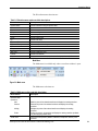
Configuration
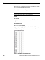
The minimum requirements for the ArbExpress AXW100 application are listed
in Table 1-1.
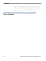
Table 1-1: Minimum system requirements
OS supported
Minimum requirements
Windows XP Professional Service Pack 1
Pentium III @ 800 MHz and higher
256 MB RAM
300 MB Free Disk Space
Microsoft Internet Explorer 5.01 and higher
.NET Framework 1.1 Redistributable
800 X 600 Display Resolution
Windows 2000
Windows 98/Me
Windows NT Service Pack 6a
The following table lists the conditions under which ArbExpress uses TekVisa
version 3.00.
Table 1-2: ArbExpress and TekVisa
AWG/AFG
Oscilloscope
LAN
TekVisa not required* (supported through raw sockets)
GPIB
TekVisa required
RS232*
Not supported
USB
TekVisa required**
* AFG and AWG2xxx series do not support LAN
** Only the AFG3xxx series instruments support USB
TekVisa required
TekVisa required
TekVisa required
TekVisa required
ArbExpress supports file transfer and control from MATLAB version 6.1,
release 12.1. To use this feature, install TekVisa version 3.00 on the PC.
Installation
This section describes how to install the ArbExpress AXW100 application using
the InstallShield Wizard. The installation program setup.exe installs the
ArbExpress software. Do the following to install the ArbExpress software:
2
1.
Insert the ArbExpress CD-ROM into the CD-ROM drive.
2.
If the installation program does not automatically start, find setup.exe under
the folder \ArbExpress on the CD-ROM and double-click it. The
InstallShield wizard displays the Splash Screen.
3.
Follow the instructions given by the InstallShield wizard.
ArbExpress® AXW100 Waveform Creation and Editing Tool
Overview
4.
The installation follows this sequence of steps: Welcome, License
Agreement, Choose Destination Location, Start Copying Files, Setup Status,
and View Release Notes (optional).
Click Next to continue and navigate through the InstallShield wizard.
Click Back if you want to change the settings in the previous window.
5.
In the Welcome window, click Next to display the License Agreement
window.
6.
In the License Agreement window, do the following:
Read the License Agreement carefully.
Select the I accept the terms of the License agreement option to
continue.
7.
After you have selected the I accept the terms of the License agreement
option, click Next to display the Choose Install Folder window.
8.
In the Choose Destination Location window, do one of the following:
9.
To install ArbExpress in the default folder C:\Program
Files\Tektronix\ArbExpress click Next.
To change the location where you would like to install the ArbExpress
software, click Browse and browse to the location.
Click Next to display the Start Copying Files window. This window
displays the disk space available and the disk space required to install
ArbExpress.
10. Click Next to start installation. The Setup Status window displays a progress
bar. ArbExpress will be installed in the selected folder with a shortcut in the
Start menu.
11. When the installation is complete, the message "ArbExpress Software Setup
completed successfully" is displayed. If you do not have TekVisa
version 3.00 and .NET Runtime Framework version 1.1 installed on your
computer, ArbExpress detects this and displays a message to install these
before running ArbExpress.
You can install TekVisa version 3.00 from the folder \TekVisa
and .NET Runtime Framework version 1.1 from the folder
\DotNet Framework available in the ArbExpress CD-ROM.
12. Note that the USB Device Driver may not install automatically.
To install the driver manually, power on the USBTMC compliant instrument
and connect it to the computer.
ArbExpress® AXW100 Waveform Creation and Editing Tool
3
Overview
Follow the screens of the "Found New Hardware Wizard." Choose the
option "Install from a list or specific location (Advanced)".
In the next dialog box, choose the option "Don't choose, I will choose the
driver to install," and enter the location C:\vxipnp\winnt\tekvisa\bin. Select
TekUSB.inf (may be automatically selected) and select Open.
The driver will be installed. See the TekVisa 2.03 build 97file readme.pdf
for additional information.
13. Click Finish to exit.
Using Online Help
Select Help on the right side of the application menu bar to bring up the online
help.
Table of Contents (TOC) tab—-organizes the Help into book-like sections.
Select a book icon to open a section; select any of the topics listed under the
book.
Index tab—-enables you to scroll through alphabetical list of keywords. Select
the topic of interest to bring up the appropriate help page.
Search tab—-allows a text-based search. Follow these steps:
1.
Type the word or phrase you want to find in the search box.
2.
Select some matching words in the next box to narrow your search.
3.
Choose a topic in the lower box, and then select the Display button.
To print a topic, select the Print button from the Help Topics menu bar.
Select Options from the menu bar to access other commands, such as
annotating a topic or keeping the help window on top, or to use system
colors.
Select the Back button to return to the previous help window. Use the
hyperlink to jump from one topic to another. If the Back button is
grayed out or a jump is not available, choose the Help Topics button to
return to the originating help folder.
Browse buttons (Next >> and Previous <<) allow you to move forward
and backward through topics in the order of the Table of Contents
(TOC).
Sometimes you will see the word Note in the topic text. This indicates important
information.
4
ArbExpress® AXW100 Waveform Creation and Editing Tool
Overview
Note: Certain aspects of the online help are unique. Blue-underlined text
indicates a jump (hyperlink) to another topic. Click the blue text to jump to the
related topic. For example, select the blue text to jump to the topic on Online
Help and Related Documentation and the Back button to return to the previous
page.
You can tell when the cursor is over an active hyperlink (button, jump, or popup), because the cursor arrow changes to a small hand.
For help on specific dialog boxes, display the Contents for this help file, and then
click the following book icons to display links to specific dialog boxes:
Operating Basics> Dialog Boxes.
Printing from the Online Help
While using the ArbExpress online help, you can print topics and information
from the Help viewer. Some online help topics have color in the examples of the
displayed application. If you print this type of topic on a monochrome printer,
some information may not print because of certain colors. Instead, you should
print the topic from the PDF (portable document format) file that corresponds to
the Online Help. You can find the file in the main directory on the CD-ROM
disk. The figures of the application menus in the PDF file are gray scale so the
relevant information will appear on the printed page.
To print a single topic:
4.
Find the topic in the Contents pane.
5.
Click Print from the menu.
6.
Click Print the selected topic and click OK.
To print all topics in a selected TOC book:
1.
Find the TOC book in the Contents pane.
2.
Click Print from the menu.
3.
Click Print the selected heading and all subtopics and click OK.
Tip: If topics include expanding or drop-down hotspots, click the hotspots to
display the information before you print.
ArbExpress® AXW100 Waveform Creation and Editing Tool
5
Overview
6
ArbExpress® AXW100 Waveform Creation and Editing Tool
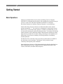
Getting Started
Basic Operations
ArbExpress AXW100 Waveform Creation and Editing Tool for Tektronix
AWG/AFG is a Windows-based software with a graphical user interface that you
can use to create, edit, and transfer standard waveforms to an Arbitrary
Waveform Generator, an Arbitrary Function Generator, or an oscilloscope.
In this online help, all menu selections are indicated as Menu name> Menu
options separated by ">". You can access a command or a menu option in more
than one way. Several main menu options are available as toolbars that you can
use instead of selecting the option from the main menu. You can show or hide the
toolbars and also create customized toolbars. Shortcut menus which open with a
right-click are provided for waveform editing, connecting to an instrument, and
transferring a waveform to an arbitrary waveform generator or an arbitrary
function generator.
The Shortcut View on the left of the screen shows options that are available in
the main menu or in the toolbars. The Shortcut View provides the most
commonly and frequently used commands.
Some dialog boxes also have a Help button that displays help for that dialog box.
Some other dialog boxes have a toolbar for basic operations like Open, Save,
Connect, Disconnect, and Show/Hide Properties.
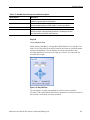
Getting Started
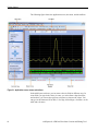
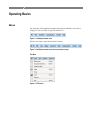
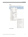
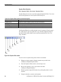
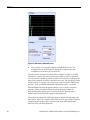
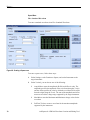
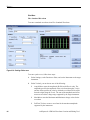
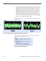
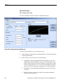
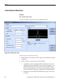
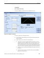
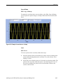
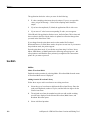
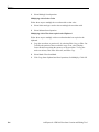
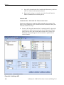
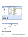
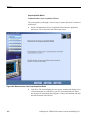
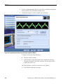
The following figure shows the application screen, the menu, and the toolbars.
Figure 2-1: Application screen, menus, and toolbars
In the ArbExpress software, you can enter values in fields in different ways. In
some fields, you type in the values, in some, you select from a drop-down list,
and in others, you can use the spin box to increase or decrease the values. You
can type in the characters K for Kilo, G for Giga, M for Mega, u for Micro, m for
milli, and n for nano.
8
ArbExpress® AXW100 Waveform Creation and Editing Tool
Getting Started
File Name Extensions
The application uses these file name extensions to identify the file type.
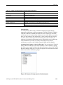
Table 2-1 lists the file name extensions.
Table 2-1: File name extensions and their descriptions
File name extensions
Description
.wfm
Oscilloscope waveform files
AWG waveform files created by AWG400-700, and AWG2000 series of waveform
generators
AWG pattern format files
Waveform files for the AFG3000 series arbitrary/function generators
Waveform files for the TDS3000 instruments
Comma separated variable files
Text files
Equation files
AWG setup information files
MATLAB compiled files
MATLAB equation files
Icon files
Compiled HTML Help files
Application extension files
Application file
.pat
.tfw
.isf
.csv
.txt
.equ/.eqa
.set
.p
.m
.ico
.chm
.dll
.exe
Application File Names and Directories
The application uses specific directories to save files. Table 2-2 lists the default
directory names.
Table 2-2: Application file names and directories
Directory
Function
C:\Program Files\Tektronix\ArbExpress\System
Stores the application files .exe, .dll, Release notes.c, and
.chm
Stores the user manual and the installation manual (.pdf)
Stores the sample waveform files (.wfm)
Stores the sample equation files (.equ)
Stores the sample MATLAB equation files (.m)
C:\Program Files\Tektronix\ArbExpress\Documentation
C:\Program Files\Tektronix\ArbExpress\Samples\Waveform
C:\Program Files\Tektronix\ArbExpress\Samples\Equation
C:\Program Files\Tektronix\ArbExpress\Samples\Tools\Matlab
You can install ArbExpress in a directory of your choice.
ArbExpress® AXW100 Waveform Creation and Editing Tool
9
Getting Started
Starting the Application
To start ArbExpress, you can do one of the following:
Run the application from the Windows Start menu. Select Start> Programs>
Tektronix ArbExpress> ArbExpress Application
Go to the folder where you have installed ArbExpress, and double-click
ArbExpress.exe
Start the application from OpenChoice Instrument Manager.
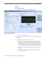
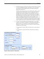
Opening a Waveform
To open a waveform, select File> Open. Browse and select the waveform file to
open. You can open files with .wfm, .pat, TekScope .wfm, .tfw, .csv, and .txt,
extensions.
When more than one waveform is opened in a window, the active waveform is a
solid line and the inactive waveform is a dashed line. You can select the active
waveform by selecting Waveform1 or Waveform2. You can set the cursor
positions by entering values in the Cursor1 and Cursor2 fields. You can drag the
cursors and the cursor readout values change. A tool tip dynamically displays the
voltage values at the cursor positions.
10
ArbExpress® AXW100 Waveform Creation and Editing Tool
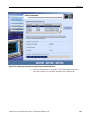
Getting Started
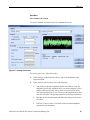
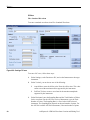
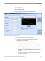
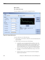
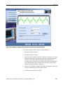
Figure 2-2: Waveform window
Creating a Waveform
File> Blank sheet, File> Standard Waveform, File> Equation Editor
To create a waveform, select the File menu. You have three items to choose
from:
Blank Sheet, where you can open a blank sheet in a window. By default, the
application opens the waveform with 1024 points which you can change
using Waveform> Properties. After you specify the number of points using
Waveform Properties, the next time you create a new blank sheet, the
application opens a blank sheet using the number of points that you
specified.
ArbExpress® AXW100 Waveform Creation and Editing Tool
11
Getting Started
Example:
a.
Open a blank sheet by selecting File> Blank Sheet. By default, the
application opens the blank sheet with 1024 points.
b.
Change the number of points to 500 using Waveform> Properties
c.
Open another blank sheet by selecting File> Blank Sheet. The
application creates a new blank sheet with 500 points.
d.
Close the application and open it again. Open a blank sheet by
selecting File> Blank Sheet. By default, the application opens the blank
sheet with 1024 points.
Standard Waveform, which displays the Standard Waveform dialog box.
Use the Standard Waveform to create any of the standard waveforms that
are available.
Equation Editor, which displays the Equation Editor dialog box. Use the
Equation Editor to create a waveform or edit an existing waveform equation.
Saving a Waveform
File> Save/Save As
To save a waveform, select File> Save. Enter the file name in the Save dialog
box to save the waveform.
To save a waveform under a different name, select File> Save As. Enter the file
name in the Save As dialog box to save the waveform. You can save the
waveform in the following formats: AWG Wfm (.wfm), AWG Pat (.pat),
AWG 2000 Wfm (.wfm), AWG. csv (.csv), and AFG Tfw (.tfw).
The application automatically saves a .set file with the same name as the
waveform file. The .set file contains the voltage values and the offset of the
waveform, and the .wfm file contains the normalized waveform.
Closing a Waveform
File> Close
To close a waveform, select File> Close. The application closes the current
window. If the waveform is not saved, you are prompted to save the waveform.
In a multiple waveform display, Close closes the active waveform.
12
ArbExpress® AXW100 Waveform Creation and Editing Tool
Getting Started
Exiting the Application
File> Exit
Select File> Exit to exit the application. If you have not saved the waveforms,
you are prompted to do so.
Shortcut Keys
You can use the following shortcut keys listed in Table 2-3 for the application
commands.
Table 2-3: Shortcut keys
Menu item
Shortcut key
File> New
File> Standard Waveform
File> Open
File> Save
File> Exit
Edit> Undo
Edit> Redo
Edit> Cut
Edit> Copy
Edit> Paste
Edit> Select All
Edit> Invert
Edit> Mirror
Edit> Freehand
Display> Zoom In
Display> Zoom Out
Display> Fit to Window
Display> Cursor
Display> Marker
Display> Properties
Ctrl + N
Ctrl + W
Ctrl + O
Ctrl + S
Ctrl + E
Ctrl + Z
Ctrl + Y
Ctrl + X
Ctrl + C
Ctrl + V
Ctrl + A
Ctrl + I
Ctrl + M
Ctrl + F
Alt + Shift + Z
Alt + Shift + X
Alt + Shift + F
Ctrl + Shift + C
Ctrl + Shift + M
Ctrl + Shift + P
ArbExpress® AXW100 Waveform Creation and Editing Tool
13
Getting Started
14
ArbExpress® AXW100 Waveform Creation and Editing Tool
Operating Basics
Menus
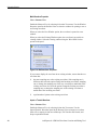
The menu bar of the application changes depending on whether a waveform is
displayed. If no waveform is open, the menu bar is:
Figure 3-1: ArbExpress main menu
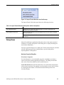
When a waveform is open, the menu bar becomes:
Figure 3-2: ArbExpress main menu when a waveform is open
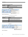
File Menu
Figure 3-3: File menu
Operating Basics
The File menu selections are:
Table 3-1: File menu options and their descriptions
Menu selection
Description
Blank Sheet
Standard Waveform
Opens a blank waveform file (.wfm)
Opens the Standard Waveform dialog box that you can use to create
standard waveforms
Opens the Equation Editor dialog box that you can use to create waveforms
Opens a waveform file (.wfm, .pat, .tfw, .csv, .txt)
Closes an open waveform file
Saves changes to the currently open waveforms
Saves files to a different file name using the Save as dialog box (.wfm (AWG
wfm, AWG2000 wfm), .pat, .csv, .tfw.)
Exits the application
Equation Editor
Open
Close
Save
Save As
Exit
16
ArbExpress® AXW100 Waveform Creation and Editing Tool
Operating Basics
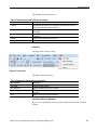
Edit Menu
The Edit menu is visible only if a waveform window is open.
Figure 3-4: Edit menu
ArbExpress® AXW100 Waveform Creation and Editing Tool
17
Operating Basics
The Edit menu selections that are available are:
Table 3-2: Edit menu options and their descriptions
Menu selection
Description
Undo
Redo
Cut
Copy
Paste
Select All
Copy to System Clipboard
Copy as Bitmap
Undoes the last operation performed on a waveform
Redoes the last operation performed on a waveform
Cuts the portion of a waveform that is between cursors
Copies the portion of a waveform that is between cursors
Displays the paste options allowing you to choose where to paste
Selects and copies the entire waveform into the memory
Copies the waveform that can be pasted in Microsoft Excel or Microsoft Word
Copies the selected waveform window as a bitmap that can be pasted into
Microsoft Word or Microsoft Excel
Inverts the portion of a waveform between the cursors
Mirrors the portion of a waveform between the cursors
Shifts the waveform by the defined amplitude or rotates the waveform by a
defined number of points
Draws a waveform along the path you trace
Allows drawing only horizontally
Allows drawing only vertically
Allows drawing a waveform by creating points. The submenu options are:
Enable Point Draw, Edit Point Draw Table..., Linear, Smooth, Staircase,
Dynamic Compile, Compile Point Draw, Next Point Draw Point, Previous Point
Draw Point, Delete Point, Clear All.
Verifies whether the active waveform can be generated in the target instrument
Invert
Mirror
Shift/Rotate
Freehand
Horizontal Draw
Vertical Draw
Point Draw
Validate Active Waveform
View Menu
Figure 3-5: View menu
18
ArbExpress® AXW100 Waveform Creation and Editing Tool
Operating Basics
The View menu selections are:
Table 3-3: View menu options and their descriptions
Menu selection
Description
Show/Hide Shortcut View
Standard Toolbar
Waveform Toolbar
Zoom Bar
Instrument Bar
Point Draw Toolbar
Status Bar
Displays and hides the shortcut view
Displays and hides the standard toolbar
Displays and hides the waveform toolbar
Displays and hides the zoom toolbar
Displays and hides the instrument bar
Displays and hides the point draw toolbar
Displays and hides the status bar
Display Menu
The Display menu is available only when a waveform is displayed in the
window.
Figure 3-6: Display menu
ArbExpress® AXW100 Waveform Creation and Editing Tool
19
Operating Basics
The Display menu selections are:
Table 3-4: Display menu options and their descriptions
Menu selection
Description
Zoom In
Zoom Out
Horizontal Zoom In
Fit to Window
Cursor
Cursor Position...
Marker
Crosshair
Graticule
Time Scale
Properties...
Zooms in to the area selected
Zooms out from the point selected
Zooms in horizontally from the point selected
Restores the view to the state that is was before the first zoom operation
Shows or hides the cursors
Positions the cursor exactly at the points or time specified
Shows or hides horizontal markers that you can set patterns and triggers
Changes the cursor type to crosshair
Shows or hides the graticule for the waveform
Displays time along the X-axis
Displays the properties color, line style, line width, and cursor colors of the
selected waveform
Waveform Menu
Figure 3-7: Waveform menu
20
ArbExpress® AXW100 Waveform Creation and Editing Tool
Operating Basics
The Waveform menu selections are:
Table 3-5: Waveform menu options and their descriptions
Menu selection
Description
Equation Editor...
Sine...
Square...
Triangle...
Pulse...
Noise...
Dc...
Exponential Rise...
Exponential Decay...
Sinc...
Sweep...
Multi-Tone...
Lorentz...
Properties...
Creates a waveform using the equation editor
Creates a sine wave
Creates a square wave
Creates a triangular wave
Creates a pulse wave
Creates a noise wave
Creates a DC wave
Creates a exponential rise wave
Creates a exponential decay wave
Creates a sinc wave
Creates a sweep wave
Creates a multi-tone wave
Creates a Lorentz wav
Displays the multi-waveform properties, waveform properties, and preferences
Math Menu
The Math menu is available only when a waveform window is open.
Figure 3-8: Math menu
The Math menu selections are:
Table 3-6: Math menu options and their descriptions
Menu selection
Description
Waveform Math...
Operations :
Add
Subtract
Multiply
Divide
Scalar Value
Adds the points of the selected waveforms and displays the resulting waveform
Subtracts the points of the selected waveforms and displays the resulting
waveform
Multiplies the points of the selected waveforms and displays the resulting
waveform
Divides the points on the waveform and displays the resulting waveform (available
only when applying a scalar value)
Performs a scalar operation (addition, subtraction, multiplication, division) on the
waveform
ArbExpress® AXW100 Waveform Creation and Editing Tool
21
Operating Basics
Table 3-6: Math menu options and their descriptions
Menu selection
Description
Copy from Clipboard
Performs an operation (addition, subtraction, multiplication, division) on the
selected waveform with points copied to the clipboard
Scales the waveform signal value to a ±1.0 range, with 0 as the center
Normalize
Communication Menu
Figure 3-9: Communication menu
The Communication menu selections are:
Table 3-7: Communication menu options and their descriptions
Menu selection
Description
AWG/AFG File Transfer...
Connects and transfers files to and from an arbitrary waveform or function
generator and allows you to change instrument parameters like clock
frequency, voltage, offset and others of the instrument connected
Connects and acquires a waveform from an oscilloscope
Guides you through steps to acquire data from a connected oscilloscope
Sends the waveform to a connected AWG/AFG
Import from Scope...
Scope Acquisition Wizard
Send Waveform to Arb
Window Menu
Figure 3-10: Window menu
22
ArbExpress® AXW100 Waveform Creation and Editing Tool
Operating Basics
The Window menu selections are:
Table 3-8: Window menu options and their descriptions
Menu selection
Description
Cascade
Arranges the open windows in the application client area from upper-left to
lower-right so that they overlap one another
Tile Horizontally
Arranges the open windows horizontally in the application client area without
overlapping
Arranges the open windows vertically in the application client area without
overlapping
Closes all open windows in the client area
Allows you to jump to an open or inactive window
Tile Vertically
Close All
List of open windows
Help Menu
The Help menu is always visible.
Figure 3-11: Help menu
The Help menu selections are:
Table 3-9: Help menu options and their descriptions
Menu selection
Description
Help Topics
Help on Window
Technical Support...
Displays the Help contents
Displays the help topic for the active window
Displays the Tektronix Technical Support Web site for the ArbExpress
application
Displays version and copyright information
About...
Use Shortcut Menu for Waveforms
You can view the shortcut menu by a right-clicking inside an open waveform
window.
ArbExpress® AXW100 Waveform Creation and Editing Tool
23
Operating Basics
Figure 3-12: Shortcut menu
The shortcut menu has the following options:
Table 3-10: Shortcut menu options and their descriptions
Menu selection
Description
Open
Save
Close
Cut
Copy
Paste
Select All
Zoom
Time Scale
Set Cursor Position
Freehand
Horizontal Draw
Vertical Draw
Waveform Properties
Opens a waveform file (.wfm, .pat, .csv, .txt)
Saves the currently selected waveform
Closes the currently selected waveform
Cuts the portion of a waveform that is between cursors
Copies the portion of a waveform that is between cursors
Pastes the selected portion of a waveform at the cursor which has a lower value
Selects and copies the entire waveform into the memory
Opens a submenu with options to Zoom in, Zoom out, and Fit to Window
Displays the waveform with time as the X-axis and voltage along the Y-axis
Positions the cursor exactly at the points or time specified
Draws a waveform along the path you trace
Allows drawing only horizontally
Allows drawing only vertically
Allows viewing and modifying properties of multiple waveforms, a selected
waveform, and the application preferences. The dialog box has three tabs: Active
Waveform, Multi-waveform, and Preferences.
Sends the waveform to the connected instrument
Send Waveform to Arb
24
ArbExpress® AXW100 Waveform Creation and Editing Tool
Operating Basics
In the Point Draw mode, a right-click inside an open waveform window displays
the following shortcut menu:
Figure 3-13: Point Draw shortcut menu
ArbExpress® AXW100 Waveform Creation and Editing Tool
25
Operating Basics
The shortcut menu has the following options:
Table 3-11: Point Draw shortcut menu options and their descriptions
Menu selection
Description
Disable Point Draw
Zoom
Disables the point draw mode
Has options that you can use to Zoom In, Zoom Out, Horizontal Zoom In, and Fit to
Window
Opens the Cursor Position dialog box that you can use to set the cursor position in
points or seconds
Changes the values on X axis into time domain
Highlights the previous point in the sequence
Highlights the next point in the sequence
Opens the point draw table where you can edit the points and set the interpolation
method
Deletes the selected point
Clears the display of all the points but the continues to display the waveform
Sets the interpolation method to use while generating the waveform. You can
choose form Smooth, Linear, and Staircase
Compiles the waveform as you click the points using the interpolation method you
have chosen
Compiles the waveform using the interpolation method you have chosen only when
you click Compile
Set Cursor Position...
Time Scale
Select Previous Point
Select Next Point
Edit Point Draw Table...
Delete Selected Point
Clear All Points
Interpolation
Dynamic Compile
Compile Draw Points
Toolbars
Standard Toolbar
View> Standard Toolbar
Enable the standard toolbar by selecting it from the View menu. The standard
toolbar is displayed, by default, below the main menu. You can place the toolbar
anywhere within the application window.
The toolbar has icons for the standard functions⎯New blank waveform, Open
existing waveform, Save the waveform, Cut waveform between cursors, Copy
waveform between cursors, Paste waveform, Undo, Redo, and Help.
26
ArbExpress® AXW100 Waveform Creation and Editing Tool
Operating Basics
Figure 3-14: Standard toolbar
Waveform Toolbar
View> Waveform Toolbar
Enable the waveform toolbar by selecting it from the View menu.
Figure 3-15: Waveform toolbar
The waveform toolbar is displayed, by default, below the standard toolbar. You
can place the toolbar anywhere within the application window. The waveform
toolbar has icons for the functions ⎯Cursors, Markers, Freehand Draw,
ArbExpress® AXW100 Waveform Creation and Editing Tool
27
Operating Basics
Horizontal Draw, Vertical Draw, Equation Editor, Basic Waveform, Advanced
Waveform, and Validate.
Zoom Bar
View> Zoom Bar
Enable the zoom bar by selecting it from the View menu.
Figure 3-16: Zoom toolbar
The zoom toolbar is displayed, by default, alongside the waveform toolbar. You
can place the toolbar anywhere within the application window. The zoom toolbar
has icons for the functions⎯Zoom In, Zoom Out, Zoom In Horizontally, and Fit
to Window.
Instrument Bar
View> Instrument Toolbar
Enable the instrument toolbar by selecting it from the View menu.
Figure 3-17: Instrument toolbar
The instrument toolbar is displayed, by default, below the main menu. You can
place the toolbar anywhere within the application window. The toolbar has icons
for the standard functions—File Transfer and Control, Scope Acquisition
Wizard, Import from Scope, and Send Waveform to Arb.
28
ArbExpress® AXW100 Waveform Creation and Editing Tool
Operating Basics
Point Draw Toolbar
Enable the point draw toolbar by selecting it from the View menu. The point
draw toolbar is displayed, by default, below the main menu. You can place the
toolbar anywhere within the application window
Figure 3-18: Point Draw toolbar
The toolbar has icons for the functions—Enable Point Draw, Select Draw Point,
Previous PD Point, Next PD point, Delete Point, Edit PD Table, Interpolation
Method, Dynamic Compile, and Compile.
Status Bar
View> Status Bar
Enable the Status Bar by selecting it from the View menu.
The application has two status bars: the Application status bar, and the
Waveform status bar.
The Application status bar is displayed at the bottom of the application window.
It shows the type of instrument that is connected and its status. You can turn on
or off the Application Status bar from the View menu.
Figure 3-19: Application status bar
ArbExpress® AXW100 Waveform Creation and Editing Tool
29
Operating Basics
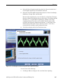
The Waveform status bar displays the sampling rate, points, signal voltage,
editing mode, and cursor difference. When viewing a standard waveform, the
voltage readout on the status bar displays the height of the waveform where it
crosses the active cursor or the vertical line of the pointer/crosshair. In the draw
mode, the voltage readout is the actual vertical height of the draw pointer.
Figure 3-20: Waveform status bar
30
ArbExpress® AXW100 Waveform Creation and Editing Tool
Operating Basics
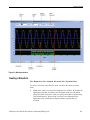
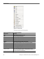
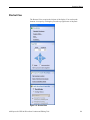
Shortcut View
The Shortcut View occupies the left part of the display. You can keep the
shortcut view open by clicking the pin at the top right corner of the panel.
Figure 3-21: Shortcut View
ArbExpress® AXW100 Waveform Creation and Editing Tool
31
Operating Basics
The shortcut panel view shows the following selections:
Table 3-12: Shortcut View options and their descriptions
Menu selection
Description
New Waveform
Allows you to create a new or blank waveform, standard waveform, or a new
equation
Allows you to shift or rotate the waveform
Allows you to acquire or import waveform from an oscilloscope
Allows you to create a new waveform in a new window or create a new
waveform in existing window. It also allows you to open a existing waveform in
either a new window or an existing window
Easy Edit
Import/Transfer Waveform
Multi-Waveform Properties
You can show or hide each selection in the shortcut panel by pressing the double
arrow at the top right corner of each panel.
New Waveform View
View> Shortcut View
Enable the Shortcut View by selecting it from the View menu. Use the New
Waveform panel in the Shortcut View to create a standard waveform, a
waveform using the equation editor, or a blank waveform. You can view and
modify the properties of one or more waveforms, and set preferences.
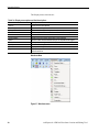
Figure 3-22: New Waveform View
You can create a standard waveform, a waveform using the equation editor, or a
blank waveform. You can display a maximum of two waveforms in a single
window.
32
ArbExpress® AXW100 Waveform Creation and Editing Tool
Operating Basics
Table 3-13: New Waveform View options and their descriptions
Menu selection
Description
Standard Waveform...
Displays a Standard Function dialog box where you can select the type of
waveform to generate and set the parameters
Displays the Equation Editor dialog box where you can select an equation
from the standard equations provided, modify it, or create a new equation
Displays a blank screen where you can draw or generate a waveform
Displays a dialog to view and modify properties of multiple waveforms, a
selected waveform, and the application preferences. The dialog box has three
tabs: Multi-waveform, Waveform, and Preferences
Equation Editor...
Blank...
Properties...
Easy Edit
View> Shortcut View
Enable the Easy Edit Bar by selecting Show/Hide Shortcut View from the View
menu. Use the Easy Edit bar to shift or rotate the waveform by a defined number
of points and amplitude. You can shift the waveform or the portion of the
waveform that is between cursors left, right, up, or down. You can rotate the
waveform left or right.
Figure 3-23: Easy Edit View
Type the number of points and amplitude by which to rotate or shift the
waveform. If the option Rotate Waveform is checked, the waveform is rotated. If
the selection is cleared, the waveform is shifted.
ArbExpress® AXW100 Waveform Creation and Editing Tool
33
Operating Basics
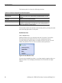
Multi-Waveform Properties
View> Shortcut View
Enable the Shortcut View by selecting it from the View menu. Use the Window
Properties panel in the Shortcut View to select the window for opening a new or
an existing waveform.
When you select the New Window option, the waveform is opened in a new
window.
When you select the Existing Window option, the waveform is opened in an
existing window. Select the existing window using the Wave Book list box
present in the panel.
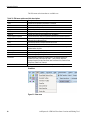
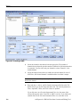
Figure 3-24: Multi-waveform Properties
If you want to display the waveform in an existing window, ensure that the new
waveform has:
the same sampling rate as the existing waveform; if the sampling rate is
different, then select the option Change the Incoming waveforms sampling
rate, to change the sampling rate of the new waveform to match that of the
existing waveform. Or, select the option Change the Existing waveform's
sampling rate, to change the sampling rate of the existing waveform to
match that of the incoming waveform.
equal number of points as the existing waveform
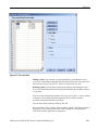
Import or Transfer Waveform
View> Shortcut View
Enable the Shortcut View by selecting it from the View menu. Use the
Import/Transfer Waveform panel in the Shortcut View to import a waveform
from a file or acquire it from an oscilloscope, File Transfer and Control, and
Scope Acquisition Wizard.
34
ArbExpress® AXW100 Waveform Creation and Editing Tool
Operating Basics
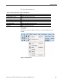
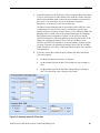
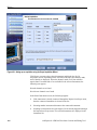
Figure 3-25: Import/Transfer Waveform from Oscilloscope
The Import/Transfer Waveform panel shows the following selections:
Table 3-14: Import/Transfer Waveform View options and their descriptions
Menu selection
Description
File Transfer and Control
Displays the File Transfer and Control dialog that you can use to transfer files to an
AWG/AFG and control the instrument
Displays the Import Waveform from Scope dialog that you can use to import a waveform
from and oscilloscope
Import Waveform from Scope
Scope Acquisition Wizard
Launches the Scope Acquisition Wizard that you can use to acquire data from a connected
oscilloscope
Dialog Boxes
Most of the ArbExpress application dialog boxes have a help topic associated
with them. To display descriptions for the dialog boxes, display the dialog box
and click the Help button.
For help on specific dialog boxes, display the Contents for this help file, and then
click the following book icons to display links to specific dialog boxes:
Operating Basics> Dialog Boxes.
Waveform Properties Dialog Box
Waveform> Properties
Use this dialog box to view and modify properties of multiple waveforms, a
selected waveform, and the application preferences. The dialog box has three
tabs: Active Waveform, Multi-waveform, and Preferences.
Active Waveform: Select the Waveform tab to view and modify the properties
of the selected waveform. For multiple waveform display, choose the waveform
by selecting the Waveform1 or Waveform2 button located just above the
waveform display.
ArbExpress® AXW100 Waveform Creation and Editing Tool
35
Operating Basics
Table 3-15: Active waveform options and their descriptions
Option
Description
Instrument
Number of Points
Select the instrument from the list.
Displays the number of points of the selected waveform. You can change this to suit the
requirements of the target instrument.
Displays the sampling rate of the selected waveform. You can change this to suit the
requirements of the target instrument.
Select the algorithm to use when resampling and recreating the waveform (Sinc, Linear, or
Add Points with zero amplitude). Marker data is not resampled, but marker data may be
added or removed.
Sampling Rate
Select resampling method
Normalize the waveform before saving
the file*
Normalizes the waveform before saving it. The waveform amplitude is set between –1 and
+1 before the waveform is saved.
* For AFG310/320, the option is always selected.
Save the waveform by selecting File> Save or File> Save As.
Multi-waveform: Select the Multi-waveform tab to set up the window in which
to display the waveforms.
Table 3-16: Multi-waveform options and their descriptions
Option
Description
New Window
Existing Window
Wave book
Change the incoming waveform's clock
Displays or opens the waveform in a new window
Displays or opens the waveform in an existing window
Displays the list of wave books to choose to display the waveform
Changes the incoming or new waveform's clock to match the clock of the existing waveform
Change the existing waveform's clock
Changes the existing waveform's clock to match the incoming or new waveform's clock
When more than one waveform is displayed in a window or a wave book, you
can select the waveform to edit or work with by selecting the Waveform1 or
Waveform2 button located just above the waveform display. When you open or
display a second waveform in the same window or wave book, the first
waveform is shown as a dotted line.
Note: A window or wave book can display a maximum of two waveforms. If you
try to open or display more than two waveforms in a single window or wave
book, you will be prompted with the message "Only two waveforms can be
opened or created in a Wave Book".
Note: Only waveforms with the same number of samples can be displayed in a
wave book.
36
ArbExpress® AXW100 Waveform Creation and Editing Tool
Operating Basics
Preferences: Use the Preferences tab to set preferences for a waveform. You can
select any of the following preferences:
Table 3-17: Preferences options and their descriptions
Option
Description
Save .set file along with .wfm and .pat
files
Show paste option before pasting
Saves the settings file along with the waveform and pattern files. The .set file
contains the voltage and offset of the waveform. Enable this before creating a
waveform
Displays the Paste option dialog box before pasting the contents
Always enables the instrument's
outputs after transferring the waveform
Switches on the destination channel to which the waveform is transferred and sets
the instrument in the Run mode
Paste Option Dialog Box
Edit> Paste
Use this dialog box to paste the copied portion of the waveform. You can select
any of the following Paste options.
Table 3-18: Paste options and their descriptions
Option
Description
Paste at active cursor
Prepend to the waveform
Append to the waveform
Replace between cursors
Don't show this again and always
paste at active cursor
Pastes the contents at the active cursor. The active cursor in indicated by a solid line.
Pastes the copied contents at the beginning of the waveform
Pastes the copied contents at the end of the waveform
Pastes the copied contents the between the cursors
If checked, always pastes the copied contents at the active cursors and does not display
the dialog box next time
If you select Don't show this again and always paste at active cursor, the
application does not display the Paste Options dialog box and always pastes the
contents at the active cursor.
Shift/Rotate Dialog Box
Edit> Shift/Rotate
Use this dialog box to set the number of points and amplitude by which to shift or
rotate the waveform or the portion of the waveform that is between cursors. The
amplitude value is used only during waveform shift and not during waveform
rotation.
ArbExpress® AXW100 Waveform Creation and Editing Tool
37
Operating Basics
The direction of rotation is either left or right. The direction of shift is either up,
down, left, or right.
Table 3-19: Shift/Rotate options and their descriptions
Option
Description
Points
Sets the number of points by which to rotate the waveform
Amplitude
Vertical Segment
Shift Up
Shift Down
Sets the amplitude by which to shift the waveform
Shifts the waveform up by the specified amplitude
Shifts the waveform down by the specified amplitude
Horizontal Segment
Rotate Right
Rotates the waveform to the right by the specified number of points
Rotate Left
Rotates the waveform to the left by the specified number of points
Shift Right
Shifts the waveform to the right by the specified number of points
Shift Left
Shifts the waveform to the left by the specified number of points
Point Draw Table Dialog Box
Edit> Point Draw> Edit Point Draw Table
Use this dialog box to enter waveform points in a blank table or edit a point draw
table that already has points in it. This table works similar to a Microsoft Excel
worksheet.
Table 3-20: Point Draw Table options and their descriptions
Option
Description
Insert Point
Inserts a row (point) above the selected row
Delete Point
Clear All
Interpolation
Delete the selected row (point)
Clears all the rows (points) in the table
Sets the interpolation method to Linear, Smooth, or Staircase
X Value
Displays the X value in Positions (points) or in Time ( seconds)
The application checks the values you enter for the following:
38
X-value (sampling point) must always be unique. If you try to repeat this
value, you get the message – Values of the sampling index should be
unique.
If you leave the amplitude (Y) blank, the applications fills it with a zero.
If you enter a Y value but no corresponding X value, an error appears.
ArbExpress® AXW100 Waveform Creation and Editing Tool
Operating Basics
Click OK and if the application finds no errors, the Point Draw Table closes and
the waveform in the Wave Book window is updated to reflect the changes that
you made in the Point Draw Table.
Cursor Position Dialog Box
Display> Cursor Position
Use this dialog box to specify the cursor position in points or in seconds.
Table 3-21: Cursor Position options and their descriptions
Option
Description
Points/Seconds
Points
Seconds
Cursor Position
Cursor 1
Cursor 2
Select Points to set the cursor position in points
Select Seconds to set the cursor position in seconds
Enter the position for Cursor 1 in the units selected in the previous option
Enter the position for Cursor 2 in the units selected in the previous option
Display Properties Dialog Box
Display> Properties
Use this dialog box to view the waveform display properties.
Table 3-22: Display Properties options and their descriptions
Option
Description
Waveform Name
Enable Graticule
Background Color
Waveform Properties
Lists the waveforms available in the active window
Displays the graticule when checked
Changes the background color of the waveform window
Color
Line Style
Line Width
Marker Color
Displays the waveform color and allows you to change the waveform color
Displays the waveform line style and allows you to change the style
Displays the waveform line width and allows you to change the line width
Marker1
Marker2
Cursor Color
Displays the color of Marker1 and allows you to change it
Displays the color of Marker2 and allows you to change it
Cursor1
Cursor2
Preview
Displays the color of Cursor1 and allows you to change it
Displays the color of Cursor2 and allows you to change it
Displays the preview of the waveform
When more than one waveform is displayed in one wave book or window, the
inactive waveform is displayed with a dashed line style and the active waveform
is displayed with a solid line style.
ArbExpress® AXW100 Waveform Creation and Editing Tool
39
Operating Basics
Equation Editor Dialog Box
File> Equation Editor, Waveform> Equation Editor
Use this dialog box to create a waveform using the Equation Editor. You can set
the following parameters in the Equation Editor dialog box.
Table 3-23: Equation Editor options and their descriptions
Option
Description
Number of Points
Sampling Rate
Total Range
Lock Total Range
Indicates the number of samples, typically in one cycle of the waveform
Indicates the number of samples per second
Indicates the duration of the waveform in seconds
Locks the Total Range value when checked. You can then edit only the other two variables
The Equation Editor has a toolbar that has icons for opening a file and saving a
file. Click Open to open an equation file (.equ) from the sample files that are
provided. Use the other toolbar icons to perform operations like Close, Cut,
Copy, and Paste.
Figure 3-26: Equation Editor toolbar
You can create an equation using either of these two methods:
40
Editing an existing equation. Sample equations are provided in the
\ArbExpress\Samples\Equation folder.
1.
From the Equation Editor window, click the Open icon.
2.
Browse the equations (.equ or .eqa) listed in the folder
\ArbExpress\Samples\Equation.
3.
Edit the equation using the Edit menu or by placing the pointer over the
equation.
Using the functions, operators, and constants
ArbExpress® AXW100 Waveform Creation and Editing Tool
Operating Basics
1.
Create an equation in the edit area, using the functions and operators
available under Function. Always define a range first.
2.
Under Settings, set the Total Range to the sum of all the ranges you have
defined in the equation. To do this, enter the Number of Points and
Sampling Rate. Once you set the Total Range, you can lock it and change
the Number of Points or Sampling Rate.
3.
Click Compile. The compiled equation is displayed in Preview. The
compilation status and messages are displayed in Output.
Click the Compile button to compile the equation. If the equation compiles
without any errors, the application displays the waveform in the specified
window. If compilation errors occur, the application displays a message in the
output pane. The OK button is enabled only if the compilation is successful.
The application supports the AWG2000 equation editor model. Equations created
using the equation editor cannot be used on the AWG400 through AWG700
series waveform generators. Refer to the Equation Editor Reference for more
details. Equations created using the equation editor cannot be used on the
AWG400 through AWG700 series waveform generators.
Click the Send to Arb button to transfer the waveform to an AWG or an AFG.
This button is enabled only when an instrument (AWG or AFG) is connected.
You can select the channel to send the waveform to.
Click the Multi-Waveform Properties button to view or vary the waveform
properties. When you click the Multi-Waveform Properties button, the
Waveform Properties dialog opens. Note that the Active Waveform tab is
disabled when invoked from the equation editor dialog box.
ArbExpress® AXW100 Waveform Creation and Editing Tool
41
Operating Basics
Sine Wave Dialog Box
File> Standard Waveform
Use this dialog box to create a sine waveform. You can set the following
parameters in the Standard Waveform dialog box.
Table 3-24: Sine Wave options and their descriptions
Option
Description
Settings
Function
Instrument
Vertical
Select a standard function from the list
Select an instrument from the list
Amp/Offset
Amplitude
Offset
Max/Min
Maximum
Minimum
Full DAC Value
Horizontal
Select Amp/Offset to set the amplitude and offset for the selected waveform
Enter the amplitude of the waveform in volts
Enter the offset of the waveform in volts
Select Max/Min to set the amplitude voltage range for the selected waveform
Enter the maximum amplitude or the waveform in volts
Enter the minimum amplitude or the waveform in volts
Select Full DAC Value to set the waveform values between −1 and + 1
Show Advanced Mode
Frequency
Cycles
Phase
Select this to show the advanced options for the horizontal parameters
Enter the frequency in Hertz. Enter M for Megahertz, and G for Gigahertz
Enter the number of cycles in the waveform
Enter the phase in degrees
Advanced Options
Horizontal
Frequency
Samples/sec
Points/cycle
Displays the frequency as Samples per Second divided by Number of Points per Cycle. You can
set the frequency by entering the number of Samples per Second and the Number of Points per
cycle.
You can lock the desired frequency and adjust either the Samples per Second or the Points per
Cycle to achieve the frequency.
You can lock the desired Samples per Second and adjust either the Frequency or the Points per
Cycle to achieve the sampling rate.
You can lock the desired Points per Cycle and adjust either the Frequency or the Samples per
Second to achieve the number of points per cycles.
The Show Advanced Mode option is not available for the AFG3xxx series of
instruments. For the AFG3xxx series of instruments, type the Total Number of
Points, Frequency in Hertz, Phase in degrees, and Cycles. The Sampling Rate is a
fixed value for the selected instrument. The Sampling Rate depends on the total
number of points. For the AFG3101 and the AFG3102 instruments, if the total
number of points exceeds 16,384 (16 K points), the sampling rate changes from
1 GHz to 250 MHz. For the AFG3251 and AFG3252 instruments, if the total
42
ArbExpress® AXW100 Waveform Creation and Editing Tool
Operating Basics
number of points exceeds 16,384 (16 K points), the sampling rate changes from
2 GHz to 250 MHz.
Click the Preview button to preview the waveform, click the Default button to
restore the default values for the waveform, click the OK button to save your
current values and create the waveform, and click the Send to Arb button to send
the waveform directly to an arbitrary waveform or function generator that is
connected. Send to Arb is enabled only when an instrument (AWG or AFG) is
connected.
Click the Multi-Waveform Properties button to view or vary the waveform
properties. When you click the Multi-Waveform Properties button, the
Waveform Properties dialog opens. Note that the Active Waveform tab is
disabled when invoked from the standard waveform dialog box.
If the number of points is fewer than the number of points supported by the
instrument, the following options appear when you click Preview:
Table 3-25: Waveform padding options
Option
Description
Manually change the Horizontal settings
to reach minimum number of points
Add zeros to achieve minimum number
of points
Add last vector to achieve minimum
number of points
Select this and change the parameters to increase the total number of points in the
waveform to achieve the minimum number of points.
Select this to achieve the minimum number of points by appending points of zero
voltage to the waveform.
Select this to achieve the minimum number of points by appending points with the
voltage value of the last point to the waveform.
Select one of the options and click OK.
ArbExpress® AXW100 Waveform Creation and Editing Tool
43
Operating Basics
Square Wave Dialog Box
File> Standard Waveform
Use this dialog box to create a square waveform. You can set the following
parameters in the Standard Waveform dialog box:
Table 3-26: Square Wave options and their descriptions
Option
Description
Settings
Function
Instrument
Vertical
Select a standard function from the list
Select an instrument from the list
Amp/Offset
Amplitude
Offset
Max/Min
Maximum
Minimum
Full DAC Value
Horizontal
Select Amp/Offset to set the amplitude and offset for the selected waveform
Enter the amplitude of the waveform in volts
Enter the offset of the waveform in volts
Select Max/Min to set the amplitude voltage range for the selected waveform
Enter the maximum amplitude or the waveform in volts
Enter the minimum amplitude or the waveform in volts
Select Full DAC Value to set the waveform values between −1 and + 1
Show Advanced Mode
Frequency
Cycles
Phase
Duty Cycle
Select this to show the advanced options for the horizontal parameters
Enter the frequency in Hertz. Enter M for Megahertz, and G for Gigahertz
Enter the number of cycles in the waveform
Enter the phase in degrees
Enter the Duty Cycle as a percentage of the waveform width
Advanced Options
Horizontal
Frequency
Samples/sec
Points/cycle
Displays the frequency as Samples per Second divided by Number of Points per Cycle. You can
set the frequency by entering the number of Samples per Second and the Number of Points per
cycle.
You can lock the desired frequency and adjust either the Samples per Second or the Points per
Cycle to achieve the frequency.
You can lock the desired Samples per Second and adjust either the Frequency or the Points per
Cycle to achieve the sampling rate.
You can lock the desired Points per Cycle and adjust either the Frequency or the Samples per
Second to achieve the number of points per cycles.
Transitions
Rise Time
Ramp
Sine2
Fall Time
Ramp
Sine2
44
Enter the Rise time in number of points or in seconds
Select Ramp
Select Sine2
Enter the Fall time in points or in seconds
Select Ramp
Select Sine2
ArbExpress® AXW100 Waveform Creation and Editing Tool
Operating Basics
The Show Advanced Mode option is not available for the AFG3xxx series of
instruments. For the AFG3xxx series of instruments, type the Total Number of
Points, Frequency in Hertz, Phase in degrees, Cycles, and Duty Cycle. The
Sampling Rate is a fixed value for the selected instrument. The Sampling Rate
depends on the total number of points. For the AFG3101 and the AFG3102
instruments, if the total number of points exceeds 16,384 (16 K points), the
sampling rate changes from 1 GHz to 250 MHz. For the AFG3251and AFG3252
instruments, if the total number of points exceeds 16,384 (16 K points), the
sampling rate changes from 2 GHz to 250 MHz. Under Transitions (10%-90%),
set the Rise Time and Fall Time parameters.
Click the Preview button to preview the waveform, click the Default button to
restore the default values for the waveform, click the OK button to save your
current values and create the waveform, and click the Send to Arb button to send
the waveform directly to an arbitrary waveform or function generator that is
connected. Send to Arb is enabled only when an instrument (AWG or AFG) is
connected.
Click the Multi-Waveform Properties button to view or vary the waveform
properties. When you click the Multi-Waveform Properties button, the
Waveform Properties dialog opens. Note that the Active Waveform tab is
disabled when invoked from the standard waveform dialog box.
If the number of points is fewer than the number of points supported by the
instrument, the following options appear when you click Preview:
Table 3-27: Waveform padding options
Option
Description
Manually change the Horizontal settings
to reach minimum number of points
Add zeros to achieve minimum number
of points
Add last vector to achieve minimum
number of points
Select this and change the parameters to increase the total number of points in the
waveform to achieve the minimum number of points.
Select this to achieve the minimum number of points by appending points of zero
voltage to the waveform.
Select this to achieve the minimum number of points by appending points with the
voltage value of the last point to the waveform.
Select one of the options and click OK.
ArbExpress® AXW100 Waveform Creation and Editing Tool
45
Operating Basics
Triangle Wave Dialog Box
File> Standard Waveform
Use this dialog box to create a triangle waveform. You can set the following
parameters in the Standard Waveform dialog box:
Table 3-28: Triangle Wave options and their descriptions
Option
Description
Settings
Function
Instrument
Vertical
Select a standard function from the list
Select an instrument from the list
Amp/Offset
Amplitude
Offset
Max/Min
Maximum
Minimum
Full DAC Value
Horizontal
Select Amp/Offset to set the amplitude and offset for the selected waveform
Enter the amplitude of the waveform in volts
Enter the offset of the waveform in volts
Select Max/Min to set the amplitude voltage range for the selected waveform
Enter the maximum amplitude or the waveform in volts
Enter the minimum amplitude or the waveform in volts
Select Full DAC Value to set the waveform values between −1 and + 1
Show Advanced Mode
Frequency
Cycles
Phase
Select this to show the advanced options for the horizontal parameters
Enter the frequency in Hertz. Enter M for Megahertz, and G for Gigahertz
Enter the number of cycles in the waveform
Enter the phase in degrees
Advanced Options
Horizontal
Frequency
Samples/sec
Points/cycle
Displays the frequency as Samples per Second divided by Number of Points per Cycle. You can
set the frequency by entering the number of Samples per Second and the Number of Points per
cycle.
You can lock the desired frequency and adjust either the Samples per Second or the Points per
Cycle to achieve the frequency.
You can lock the desired Samples per Second and adjust either the Frequency or the Points per
Cycle to achieve the sampling rate.
You can lock the desired Points per Cycle and adjust either the Frequency or the Samples per
Second to achieve the number of points per cycle.
The Show Advanced Mode option is not available for the AFG3xxx series of
instruments. For the AFG3xxx series of instruments, type the Total Number of
Points, Frequency in Hertz, Phase in degrees, and Cycles. The Sampling Rate is a
fixed value for the selected instrument. The Sampling Rate depends on the total
number of points. For the AFG3101 and the AFG3102 instruments, if the total
number of points exceeds 16,384 (16 K points), the sampling rate changes from
1 GHz to 250 MHz. For the AFG3251 and AFG3252 instruments, if the total
46
ArbExpress® AXW100 Waveform Creation and Editing Tool
Operating Basics
number of points exceeds 16,384 (16 K points), the sampling rate changes from
2 GHz to 250 MHz.
Click the Preview button to preview the waveform, click the Default button to
restore the default values for the waveform, click the OK button to save your
current values and create the waveform, and click the Send to Arb button to send
the waveform directly to an arbitrary waveform or function generator that is
connected. Send to Arb is enabled only when an instrument (AWG or AFG) is
connected.
Click the Multi-Waveform Properties button to view or vary the waveform
properties. When you click the Multi-Waveform Properties button, the
Waveform Properties dialog opens. Note that the Active Waveform tab is
disabled when invoked from the standard waveform dialog box.
If the number of points is fewer than the number of points supported by the
instrument, the following options appear when you click Preview:
Table 3-29: Waveform padding options
Option
Description
Manually change the Horizontal settings
to reach minimum number of points
Add zeros to achieve minimum number
of points
Add last vector to achieve minimum
number of points
Select this and change the parameters to increase the total number of points in the
waveform to achieve the minimum number of points.
Select this to achieve the minimum number of points by appending points of zero
voltage to the waveform.
Select this to achieve the minimum number of points by appending points with the
voltage value of the last point to the waveform.
Select one of the options and click OK.
ArbExpress® AXW100 Waveform Creation and Editing Tool
47
Operating Basics
Pulse Wave Dialog Box
File> Standard Waveform
Use this dialog box to create a pulse waveform. You can set the following
parameters in the Standard Waveform dialog box:
Table 3-30: Pulse Wave options and their descriptions
Option
Description
Settings
Function
Instrument
Vertical
Select a standard function from the list
Select an instrument from the list
Amp/Offset
Amplitude
Offset
Max/Min
Maximum
Minimum
Full DAC Value
Horizontal
Select Amp/Offset to set the amplitude and offset for the selected waveform
Enter the amplitude of the waveform in volts
Enter the offset of the waveform in volts
Select Max/Min to set the amplitude voltage range for the selected waveform
Enter the maximum amplitude or the waveform in volts
Enter the minimum amplitude or the waveform in volts
Select Full DAC Value to set the waveform values between −1 and + 1
Show Advanced Mode
Frequency
Cycles
Delay
Pulse Width (50%)
Select this to show the advanced options for the horizontal parameters
Enter the frequency in Hertz. Enter M for Megahertz, and G for Gigahertz
Enter the number of cycles in the waveform
Enter the delay in seconds
Enter the pulse width in seconds, typically 50% of the entire waveform width
Advanced Options
Horizontal
Frequency
Samples/sec
Points/cycle
Displays the frequency as Samples per Second divided by Number of Points per Cycle. You can set
the frequency by entering the number of Samples per Second and the Number of Points per cycle.
You can lock the desired frequency and adjust either the Samples per Second or the Points per
Cycle to achieve the frequency.
You can lock the desired Samples per Second and adjust either the Frequency or the Points per
Cycle to achieve the sampling rate.
You can lock the desired Points per Cycle and adjust either the Frequency or the Samples per
Second to achieve the number of points per cycle.
Transitions
Pulse Direction
Positive
Negative
Rise Time
Ramp
Sine2
Fall Time
Ramp
48
Select the pulse direction
Select positive pulse direction
Select negative pulse direction
Enter the Rise time in number of points or in seconds
Select Ramp
Select Sine2
Enter the Fall time in points or in seconds
Select Ramp
ArbExpress® AXW100 Waveform Creation and Editing Tool
Operating Basics
Table 3-30: Pulse Wave options and their descriptions
Option
Description
Sine2
Select Sine2
The Show Advanced Mode option is not available for the AFG3xxx series of
instruments. For the AFG3xxx series of instruments, type the Total Number of
Points, Frequency in Hertz, Delay, Cycles, and Pulse Width. The Sampling Rate
is a fixed value for the selected instrument. The Sampling Rate depends on the
total number of points. For the AFG3101 and the AFG3102 instruments, if the
total number of points exceeds 16,384 (16 K points), the sampling rate changes
from 1 GHz to 250 MHz. For the AFG3251 and AFG3252 instruments, if the
total number of points exceeds 16,384 (16 K points), the sampling rate changes
from 2 GHz to 250 MHz. Under Transitions (10%-90%), set the Pulse Direction,
Rise Time, and Fall Time parameters.
Click the Preview button to preview the waveform, click the Default button to
restore the default values for the waveform, click the OK button to save your
current values and create the waveform, and click the Send to Arb button to send
the waveform directly to an arbitrary waveform or function generator that is
connected. Send to Arb is enabled only when an instrument (AWG or AFG) is
connected.
Click the Multi-Waveform Properties button to view or vary the waveform
properties. When you click the Multi-Waveform Properties button, the
Waveform Properties dialog opens. Note that the Active Waveform tab is
disabled when invoked from the standard waveform dialog box.
If the number of points is fewer than the number of points supported by the
instrument, the following options appear when you click Preview:
Table 3-31: Waveform padding options
Option
Description
Manually change the Horizontal settings
to reach minimum number of points
Add zeros to achieve minimum number
of points
Add last vector to achieve minimum
number of points
Select this and change the parameters to increase the total number of points in the
waveform to achieve the minimum number of points.
Select this to achieve the minimum number of points by appending points of zero voltage to
the waveform.
Select this to achieve the minimum number of points by appending points with the voltage
value of the last point to the waveform.
Select one of the options and click OK.
ArbExpress® AXW100 Waveform Creation and Editing Tool
49
Operating Basics
Noise Wave Dialog Box
File> Standard Waveform
Use this dialog box to create a noise waveform. You can set the following
parameters in the Standard Waveform dialog box. The Noise waveform does not
have any advanced options.
Table 3-32: Noise Wave options and their descriptions
Option
Description
Settings
Function
Instrument
Vertical
Amp/Offset
Amplitude
Offset
Max/Min
Maximum
Minimum
Full DAC Value
Select a standard function from the list
Select an instrument from the list
Select Amp/Offset to set the amplitude and offset for the selected waveform
Enter the amplitude of the waveform in volts
Enter the offset of the waveform in volts
Select Max/Min to set the amplitude voltage range for the selected waveform
Enter the maximum amplitude or the waveform in volts
Enter the minimum amplitude or the waveform in volts
Select Full DAC Value to set the waveform values between −1 and + 1
Horizontal
Gaussian White Noise
Pink Noise
Sampling Rate
Total Number of Points
Select this to create a Gaussian White Noise waveform
Select this to create a Pink Noise waveform
Enter the sampling rate for the waveform
Enter the total number of points
For the AFG3xxx series of instruments, type the Total Number of Points. The
Sampling Rate is a fixed value for the selected instrument. The Sampling Rate
depends on the total number of points. For the AFG3101 and the AFG3102
instruments, if the total number of points exceeds 16,384 (16 K points), the
sampling rate changes from 1 GHz to 250 MHz. For the AFG3251 and AFG3252
instruments, if the total number of points exceeds 16,384 (16 K points), the
sampling rate changes from 2 GHz to 250 MHz.
Click the Preview button to preview the waveform, the Default button to restore
the default values for the waveform, click the OK button to save your current
values and create the waveform, and click the Send to Arb button to send the
waveform directly to an arbitrary waveform or function generator that is
connected. Send to Arb is enabled only when an instrument (AWG or AFG) is
connected.
50
ArbExpress® AXW100 Waveform Creation and Editing Tool
Operating Basics
Click the Multi-Waveform Properties button to view or vary the waveform
properties. When you click the Multi-Waveform Properties button, the
Waveform Properties dialog opens. Note that the Active Waveform tab is
disabled when invoked from the standard waveform dialog box.
If the number of points is fewer than the number of points supported by the
instrument, the following options appear when you click Preview:
Table 3-33: Waveform padding options
Option
Description
Manually change the Horizontal settings
to reach minimum number of points
Add zeros to achieve minimum number
of points
Add last vector to achieve minimum
number of points
Select this and change the parameters to increase the total number of points in the
waveform to achieve the minimum number of points.
Select this to achieve the minimum number of points by appending points of zero
voltage to the waveform.
Select this to achieve the minimum number of points by appending points with the
voltage value of the last point to the waveform.
Select one of the options and click OK.
DC Wave Dialog Box
File> Standard Waveform
Use this dialog box to create a DC waveform. You can set the following
parameters in the Standard Waveform dialog box. The DC waveform does not
have any advanced options.
Table 3-34: DC Wave options and their descriptions
Option
Description
Settings
Function
Instrument
Vertical
Select a standard function from the list
Select an instrument from the list
Amp/Offset
Offset
Full DAC Value
Horizontal
Select Amp/Offset to set the amplitude and offset for the selected waveform
Enter the offset of the waveform in volts
Select Full DAC Value to set the waveform values between −1 and + 1
Sampling Rate
Total Number of Points
Enter the sampling rate for the waveform
Enter the total number of points in the waveform
ArbExpress® AXW100 Waveform Creation and Editing Tool
51
Operating Basics
For the AFG3xxx series of instruments, type the Total Number of Points. The
Sampling Rate is a fixed value for the selected instrument. The Sampling Rate
depends on the total number of points. For the AFG3101 and the AFG3102
instruments, if the total number of points exceeds 16,384 (16 K points), the
sampling rate changes from 1 GHz to 250 MHz. For the AFG3251 and AFG3252
instruments, if the total number of points exceeds 16,384 (16 K points), the
sampling rate changes from 2 GHz to 250 MHz.
Click the Preview button to preview the waveform, click the Default button to
restore the default values for the waveform, click the OK button to save your
current values and create the waveform, and click the Send to Arb button to send
the waveform directly to an arbitrary waveform or function generator that is
connected. Send to Arb is enabled only when an instrument (AWG or AFG) is
connected.
Click the Multi-Waveform Properties button to view or vary the waveform
properties. When you click the Multi-Waveform Properties button, the
Waveform Properties dialog opens. Note that the Active Waveform tab is
disabled when invoked from the standard waveform dialog box.
If the number of points is fewer than the number of points supported by the
instrument, the following options appear when you click Preview:
Table 3-35: Waveform padding options
Option
Description
Manually change the Horizontal settings
to reach minimum number of points
Add zeros to achieve minimum number
of points
Add last vector to achieve minimum
number of points
Select this and change the parameters to increase the total number of points in the
waveform to achieve the minimum number of points.
Select this to achieve the minimum number of points by appending points of zero
voltage to the waveform.
Select this to achieve the minimum number of points by appending points with the
voltage value of the last point to the waveform.
Select one of the options and click OK.
52
ArbExpress® AXW100 Waveform Creation and Editing Tool
Operating Basics
Exponential Rise Wave Dialog Box
File> Standard Waveform
Use this dialog box to create an exponential rise waveform. You can set the
following parameters in the Standard Waveform dialog box. The Exponential
Rise waveform does not have any advanced options.
Table 3-36: Exponential Rise Wave options and their descriptions
Option
Description
Settings
Function
Instrument
Vertical
Amp/Offset
Amplitude
Offset
Max/Min
Maximum
Minimum
Full DAC Value
Select a standard function from the list
Select an instrument from the list
Select Amp/Offset to set the amplitude and offset for the selected waveform
Enter the amplitude of the waveform in volts
Enter the offset of the waveform in volts
Select Max/Min to set the amplitude voltage range for the selected waveform
Enter the maximum amplitude or the waveform in volts
Enter the minimum amplitude or the waveform in volts
Select Full DAC Value to set the waveform values between −1 and + 1
Horizontal
Sampling Rate
Cycles
Phase
Total Number of Points
Damp Factor
Enter the sampling rate for the waveform
Enter the number of cycles in the waveform
Enter the phase in degrees
Enter the total number of points in the waveform
Enter the damp factor
For the AFG3xxx series of instruments, type the Phase in degrees, Cycles, Total
Number of Points, and Damp Factor. The Sampling Rate is a fixed value for the
selected instrument. The Sampling Rate depends on the total number of points.
For the AFG3101 and the AFG3102 instruments, if the total number of points
exceeds 16,384 (16 K points), the sampling rate changes from 1 GHz to 250
MHz. For the AFG3251 and AFG3252 instruments, if the total number of points
exceeds 16,384 (16 K points), the sampling rate changes from 2 GHz to 250
MHz.
Click the Preview button to preview the waveform, click the Default button to
restore the default values for the waveform, click the OK button to save your
current values and create the waveform, and click the Send to Arb button to send
the waveform directly to an arbitrary waveform or function generator that is
connected. Send to Arb is enabled only when an instrument (AWG or AFG) is
connected.
ArbExpress® AXW100 Waveform Creation and Editing Tool
53
Operating Basics
Click the Multi-Waveform Properties button to view or vary the waveform
properties. When you click the Multi-Waveform Properties button, the
Waveform Properties dialog opens. Note that the Active Waveform tab is
disabled when invoked from the standard waveform dialog box.
If the number of points is fewer than the number of points supported by the
instrument, the following options appear when you click Preview:
Table 3-37: Waveform padding options
Option
Description
Manually change the Horizontal settings
to reach minimum number of points
Add zeros to achieve minimum number
of points
Add last vector to achieve minimum
number of points
Select this and change the parameters to increase the total number of points in the
waveform to achieve the minimum number of points.
Select this to achieve the minimum number of points by appending points of zero
voltage to the waveform.
Select this to achieve the minimum number of points by appending points with the
voltage value of the last point to the waveform.
Select one of the options and click OK.
54
ArbExpress® AXW100 Waveform Creation and Editing Tool
Operating Basics
Exponential Decay Wave Dialog Box
File> Standard Waveform
Use this dialog box to create an exponential decay waveform. You can set the
following parameters in the Standard Waveform dialog box. The Exponential
Decay waveform does not have any advanced options.
Table 3-38: Exponential Decay Wave options and their descriptions
Option
Description
Settings
Function
Instrument
Vertical
Amp/Offset
Amplitude
Offset
Max/Min
Maximum
Minimum
Full DAC Value
Select a standard function from the list
Select an instrument from the list
Select Amp/Offset to set the amplitude and offset for the selected waveform
Enter the amplitude of the waveform in volts
Enter the offset of the waveform in volts
Select Max/Min to set the amplitude voltage range for the selected waveform
Enter the maximum amplitude or the waveform in volts
Enter the minimum amplitude or the waveform in volts
Select Full DAC Value to set the waveform values between −1 and + 1
Horizontal
Sampling Rate
Cycles
Phase
Total Number of Points
Damp Factor
Enter the sampling rate for the waveform
Enter the number of cycles in the waveform
Enter the phase in degrees
Enter the total number of points in the waveform
Enter the damp factor
For the AFG3xxx series of instruments, type the Phase in degrees, Cycles, Total
Number of Points, and Damp Factor. The Sampling Rate is a fixed value for the
selected instrument. The Sampling Rate depends on the total number of points.
For the AFG3101 and the AFG3102 instruments, if the total number of points
exceeds 16,384 (16 K points), the sampling rate changes from 1 GHz to
250 MHz. For the AFG3251 and AFG3252 instruments, if the total number of
points exceeds 16,384 (16 K points), the sampling rate changes from 2 GHz to
250 MHz.
Click the Preview button to preview the waveform, click the Default button to
restore the default values for the waveform, click the OK button to save your
current values and create the waveform, and click the Send to Arb button to send
the waveform directly to an arbitrary waveform or function generator that is
connected. Send to Arb is enabled only when an instrument (AWG or AFG) is
connected.
ArbExpress® AXW100 Waveform Creation and Editing Tool
55
Operating Basics
Click the Multi-Waveform Properties button to view or vary the waveform
properties. When you click the Multi-Waveform Properties button, the
Waveform Properties dialog opens. Note that the Active Waveform tab is
disabled when invoked from the standard waveform dialog box.
If the number of points is fewer than the number of points supported by the
instrument, the following options appear when you click Preview:
Table 3-39: Waveform padding options
Option
Description
Manually change the Horizontal settings
to reach minimum number of points
Add zeros to achieve minimum number
of points
Add last vector to achieve minimum
number of points
Select this and change the parameters to increase the total number of points in the
waveform to achieve the minimum number of points.
Select this to achieve the minimum number of points by appending points of zero
voltage to the waveform.
Select this to achieve the minimum number of points by appending points with the
voltage value of the last point to the waveform.
Select one of the options and click OK.
56
ArbExpress® AXW100 Waveform Creation and Editing Tool
Operating Basics
Sinc Wave Dialog Box
File> Standard Waveform
Use this dialog box to create a Sinc waveform. You can set the following
parameters in the Standard Waveform dialog box. The Sinc waveform does not
have any advanced options.
Table 3-40: Sinc Wave options and their descriptions
Option
Description
Settings
Function
Instrument
Vertical
Amp/Offset
Amplitude
Offset
Max/Min
Maximum
Minimum
Full DAC Value
Select a standard function from the list
Select an instrument from the list
Select Amp/Offset to set the amplitude and offset for the selected waveform
Enter the amplitude of the waveform in volts
Enter the offset of the waveform in volts
Select Max/Min to set the amplitude voltage range for the selected waveform
Enter the maximum amplitude or the waveform in volts
Enter the minimum amplitude or the waveform in volts
Select Full DAC Value to set the waveform values between −1 and + 1
Horizontal
Sampling Rate
Phase
Cycles
Total Number of Points
Number of Zero Crossings
Enter the sampling rate for the waveform
Enter the phase in degrees
Enter the number of cycles in the waveform
Enter the total number of points in the waveform
Enter the number of zero crossings for the waveform
For the AFG3xxx series of instruments, type the Phase in degrees, Cycles, Total
Number of Points, and Number of Zero Crossings. The Sampling Rate is a fixed
value for the selected instrument. The Sampling Rate depends on the total
number of points. For the AFG3101 and the AFG3102 instruments, if the total
number of points exceeds 16,384 (16 K points), the sampling rate changes from
1 GHz to 250 MHz. For the AFG3251 and AFG3252 instruments, if the total
number of points exceeds 16,384 (16 K points), the sampling rate changes from
2 GHz to 250 MHz.
Click the Preview button to preview the waveform, click the Default button to
restore the default values for the waveform, click the OK button to save your
current values and create the waveform, and click the Send to Arb button to send
the waveform directly to an arbitrary waveform or function generator that is
connected. Send to Arb is enabled only when an instrument (AWG or AFG) is
connected.
ArbExpress® AXW100 Waveform Creation and Editing Tool
57
Operating Basics
Click the Multi-Waveform Properties button to view or vary the waveform
properties. When you click the Multi-Waveform Properties button, the
Waveform Properties dialog opens. Note that the Active Waveform tab is
disabled when invoked from the standard waveform dialog box.
If the number of points is fewer than the number of points supported by the
instrument, the following options appear when you click Preview:
Table 3-41: Waveform padding options
Option
Description
Manually change the Horizontal settings
to reach minimum number of points
Add zeros to achieve minimum number
of points
Add last vector to achieve minimum
number of points
Select this and change the parameters to increase the total number of points in the
waveform to achieve the minimum number of points.
Select this to achieve the minimum number of points by appending points of zero
voltage to the waveform.
Select this to achieve the minimum number of points by appending points with the
voltage value of the last point to the waveform.
Select one of the options and click OK.
58
ArbExpress® AXW100 Waveform Creation and Editing Tool
Operating Basics
Sweep Wave Dialog Box
File> Standard Waveform
Use this dialog box to create a Sweep waveform. You can set the following
parameters in the Standard Waveform dialog box. The Sweep waveform does not
have any advanced options.
Table 3-42: Sweep Wave options and their descriptions
Option
Description
Settings
Function
Instrument
Vertical
Amp/Offset
Amplitude
Offset
Max/Min
Maximum
Minimum
Full DAC Value
Select a standard function from the list
Select an instrument from the list
Select Amp/Offset to set the amplitude and offset for the selected waveform
Enter the amplitude of the waveform in volts
Enter the offset of the waveform in volts
Select Max/Min to set the amplitude voltage range for the selected waveform
Enter the maximum amplitude or the waveform in volts
Enter the minimum amplitude or the waveform in volts
Select Full DAC Value to set the waveform values between −1 and + 1
Horizontal
Start Frequency
End Frequency
Time Duration*
Sampling Rate
Total Number of Points**
Enter the frequency that you want at the beginning of the waveform
Enter the frequency that you want at the end of the waveform
Enter the time between the start and end of the waveform
Enter the sampling rate for the waveform
Enter the total number of points that make up the waveform
* For the AFG3xxx series of instruments, type the Start Frequency, End
Frequency, and Total Number of Points. The Sampling Rate is a fixed value for
the selected instrument. The Sampling Rate depends on the total number of
points. The Time Duration is calculated according to the following equation:
For the AFG3101 and the AFG3102 instruments, if the total number of points
exceeds 16,384 (16 K points), the sampling rate changes from 1 GHz to 250
MHz. For the AFG3251 and AFG3252 instruments, if the total number of points
exceeds 16,384 (16 K points), the sampling rate changes from 2 GHz to 250
MHz.
ArbExpress® AXW100 Waveform Creation and Editing Tool
59
Operating Basics
** The field Total Number of Points is disabled for the AWG7xx, AW6xx,
AWG5xx, AWG4xx, AWG2xxx, and AFG3xx series of instruments. The
application calculates the Total Number of Points as the product of Time
Duration and Sampling Rate.
Click the Preview button to preview the waveform, click the Default button to
restore the default values for the waveform, click the OK button to save your
current values and create the waveform, and click the Send to Arb button to send
the waveform directly to an arbitrary waveform or function generator that is
connected. Send to Arb is enabled only when an instrument (AWG or AFG) is
connected.
Click the Multi-Waveform Properties button to view or vary the waveform
properties. When you click the Multi-Waveform Properties button, the
Waveform Properties dialog opens. Note that the Active Waveform tab is
disabled when invoked from the standard waveform dialog box.
If the number of points is fewer than the number of points supported by the
instrument, the following options appear when you click Preview:
Table 3-43: Waveform padding options
Option
Description
Manually change the Horizontal settings
to reach minimum number of points
Add zeros to achieve minimum number
of points
Add last vector to achieve minimum
number of points
Select this and change the parameters to increase the total number of points in the
waveform to achieve the minimum number of points.
Select this to achieve the minimum number of points by appending points of zero
voltage to the waveform.
Select this to achieve the minimum number of points by appending points with the
voltage value of the last point to the waveform.
Select one of the options and click OK.
60
ArbExpress® AXW100 Waveform Creation and Editing Tool
Operating Basics
Multi-Tone Wave Dialog Box
File> Standard Waveform
Use this dialog box to create a Multi-Tone waveform. You can set the following
parameters in the Standard Waveform dialog box. The Multi-Tone waveform
does not have any advanced options.
Table 3-44: Multi-tone Wave options and their descriptions
Option
Description
Settings
Function
Instrument
Vertical
Amp/Offset
Amplitude
Offset
Max/Min
Maximum
Minimum
Full DAC Value
Select a standard function from the list
Select an instrument from the list
Select Amp/Offset to set the amplitude and offset for the selected waveform
Enter the amplitude of the waveform in volts
Enter the offset of the waveform in volts
Select Max/Min to set the amplitude voltage range for the selected waveform
Enter the maximum amplitude or the waveform in volts
Enter the minimum amplitude or the waveform in volts
Select Full DAC Value to set the waveform values between −1 and + 1
Horizontal
Start Frequency
End Frequency
Tone Spacing*
Sampling Rate
Total Number of Points**
Enter the frequency that you want at the beginning of the waveform
Enter the frequency that you want at the end of the waveform
Enter the frequency interval between the frequencies that make up waveform
Enter the sampling rate for the waveform
Enter the total number of points
* For the AFG3xxx series of instruments, type the Start Frequency, End
Frequency, and Total Number of Points. The Sampling Rate is a fixed value for
the selected instrument. The Sampling Rate depends on the total number of
points.
The Tone Spacing is calculated according to the following equation:
For the AFG3101 and the AFG3102 instruments, if the total number of points
exceeds 16,384 (16 K points), the sampling rate changes from 1 GHz to
250 MHz. For the AFG3251 and AFG3252 instruments, if the total number of
points exceeds 16,384 (16 K points), the sampling rate changes from 2 GHz to
250 MHz.
ArbExpress® AXW100 Waveform Creation and Editing Tool
61
Operating Basics
**The field Total Number of Points is disabled for the AWG7xx, AW6xx,
AWG5xx, AWG4xx, AWG2xxx, and AFG3xx series of instruments. The Total
Number of Points is calculated according to the following equation:
Click the Preview button to preview the waveform, click the Default button to
restore the default values for the waveform, click the OK button to save your
current values and create the waveform, and click the Send to Arb button to send
the waveform directly to an arbitrary waveform or function generator that is
connected. Send to Arb is enabled only when an instrument (AWG or AFG) is
connected.
Click the Multi-Waveform Properties button to view or vary the waveform
properties. When you click the Multi-Waveform Properties button, the
Waveform Properties dialog opens. Note that the Active Waveform tab is
disabled when invoked from the standard waveform dialog box.
If the number of points is fewer than the number of points supported by the
instrument, the following options appear when you click Preview:
Table 3-45: Waveform padding options
Option
Description
Manually change the Horizontal settings
to reach minimum number of points
Add zeros to achieve minimum number
of points
Add last vector to achieve minimum
number of points
Select this and change the parameters to increase the total number of points in the
waveform to achieve the minimum number of points.
Select this to achieve the minimum number of points by appending points of zero
voltage to the waveform.
Select this to achieve the minimum number of points by appending points with the
voltage value of the last point to the waveform.
Select one of the options and click OK.
62
ArbExpress® AXW100 Waveform Creation and Editing Tool
Operating Basics
Lorentz Wave Dialog Box
File> Standard Waveform
Use this dialog box to create a Lorentz waveform. You can set the following
parameters in the Standard Waveform dialog box. The Lorentz waveform does
not have any advanced options.
Table 3-46: Lorentz Wave options and their descriptions
Option
Description
Settings
Function
Instrument
Vertical
Amp/Offset
Amplitude
Offset
Max/Min
Maximum
Minimum
Full DAC Value
Select a standard function from the list
Select an instrument from the list
Select Amp/Offset to set the amplitude and offset for the selected waveform
Enter the amplitude of the waveform in volts
Enter the offset of the waveform in volts
Select Max/Min to set the amplitude voltage range for the selected waveform
Enter the maximum amplitude or the waveform in volts
Enter the minimum amplitude or the waveform in volts
Select Full DAC Value to set the waveform values between −1 and + 1
Horizontal
Sampling Rate
Phase
Cycles
Total Number of Points*
Time Delay **
Half Width
Enter the number of samples per second
Enter the phase in degrees
Enter the number of cycles in the waveform
Enter the total number of points in the waveform
Enter the delay in seconds
Enter the half width
* The field Total Number of Points is disabled for the AWG7xx, AW6xx,
AWG5xx, AWG4xx, AWG2xxx, and AFG3xx series of instruments. Type the
Sampling Rate of the waveform, the number of Cycles, and the Phase in degrees.
Enter the Time Delay and Half Width. The Total number of points is given by:
The Total number of points is given by:
** For the AFG3xxx series of instruments, type the Phase in degrees, Cycles,
Half Width, and Total Number of Points. The Sampling Rate is a fixed value for
the selected instrument. The Sampling Rate depends on the total number of
points. For the AFG3101 and the AFG3102 instruments, if the total number of
points exceeds 16,384 (16 K points), the sampling rate changes from 1 GHz to
250 MHz.
ArbExpress® AXW100 Waveform Creation and Editing Tool
63
Operating Basics
For the AFG3251 and AFG3252 instruments, if the total number of points
exceeds 16,384 (16 K points), the sampling rate changes from 2 GHz to 250
MHz.
For AFG3xx and AFG3xxxx series of instruments Time Delay is calculated
according to the following equation:
Click the Preview button to preview the waveform, click the Default button to
restore the default values for the waveform, click the OK button to save your
current values and create the waveform, and click the Send to Arb button to send
the waveform directly to an arbitrary waveform or function generator that is
connected. Send to Arb is enabled only when an instrument (AWG or AFG) is
connected.
Click the Multi-Waveform Properties button to view or vary the waveform
properties. When you click the Multi-Waveform Properties button, the
Waveform Properties dialog opens. Note that the Active Waveform tab is
disabled when invoked from the standard waveform dialog box.
If the number of points is fewer than the number of points supported by the
instrument, the following options appear when you click Preview:
Table 3-47: Waveform padding options
Option
Description
Manually change the Horizontal settings
to reach minimum number of points
Add zeros to achieve minimum number
of points
Add last vector to achieve minimum
number of points
Select this and change the parameters to increase the total number of points in the
waveform to achieve the minimum number of points.
Select this to achieve the minimum number of points by appending points of zero
voltage to the waveform.
Select this to achieve the minimum number of points by appending points with the
voltage value of the last point to the waveform.
Select one of the options and click OK.
64
ArbExpress® AXW100 Waveform Creation and Editing Tool
Operating Basics
File Transfer and Instrument Control Dialog Box
Communication> AWG/AFG File Transfer and Control
Use this dialog box to control the instrument from the application.
Table 3-48: File Transfer and Instrument Control options and their descriptions
Option
Description
Arb List
Instrument Folders
Instrument Files
PC Folders
PC Files
Lists the instruments that can be connected
Lists the folders on the instrument's hard disk drive
Lists the files in the folder selected on the instrument's hard disk
Lists the folders on the PC's hard disk drive
Lists the files in the folder selected on the PC's hard disk
Instrument Control
Channel
Output ON
Load File to AWG
Selects the channel that you want to control
Turns the output on or off
Select the source folder from the instrument folder list. Enter or select the file to load. You can
drag and drop the file from the Instrument's file list and the file name automatically appears here
Vertical
Filter
Control the vertical parameters
Lists the filters available that you can select from. Use this to filter frequencies greater than the
value specified.
Enter the voltage for the waveform
Enter or select the offset for the waveform
Voltage
Offset
Marker1
High
Low
Marker2
High
Low
Clock
Run/Stop
Apply
Set the High value for Marker1
Set the Low value for Marker1
Set the High value for Marker2
Set the Low value for Marker2
Enter the clock frequency
Changes the instrument from the Run to Stop mode or vice versa
Applies the changes to the waveform
For the AFG3xx series, you can transfer the waveform files in the following
directions — PC to Edit memory, PC to User memory, and Edit memory to User
memory.
For the AFG3xxx series, you can transfer the waveform in the following
directions — PC to Edit memory, PC to User memory, Edit memory to User
memory, and Edit memory to PC.
ArbExpress® AXW100 Waveform Creation and Editing Tool
65
Operating Basics
When you transfer a waveform from the Edit memory to the PC, the file has the
name EMEMFile in the destination folder. When you transfer a waveform from
the PC to the Edit memory, the EMEM waveform text box shows the waveform
file name. When you drag the EMEM file to User<n>, the User<n> text box
shows the file name as EMEMFile.
When you drag a file from the PC Files list and drop it to the destination Edit or
User memory, the destination text "Drag source file and drop here" is replaced
with the name of the transferred file. When you close the dialog box or reinvoke
it, the destination text reappears.
Waveform Math Dialog Box
Math> Waveform Math
Use this dialog box to perform mathematical operation on the selected portion of
the waveform. To operate with the selected waveform, you can either use a
standard waveform, a scalar value, or a waveform that you have copied to the
clipboard.
The mathematical operations that are available are Add, Subtract, Multiply, and
Divide. Division is applicable only when you use a scalar value or copy from the
clipboard.
Table 3-49: Waveform Math options and their descriptions
Option
Description
Waveform Library
Select the waveform
Amplitude Pk-Pk
Cycles
Phase
Duty Cycle/ Pulse
Width/Damp Factor
Scalar Value
Select a standard waveform from the list. This appears in the Math Source preview.
Type the amplitude in volts of the selected waveform
Type the number of cycles of the selected waveform
Type the phase in degrees of the selected waveform
Type the duty cycle, pulse width, or the Damp Factor for the selected waveform
Amplitude
Copy from clipboard
Operation
Type the amplitude in volts
Uses the waveform copied to the memory to perform math operations
Add
Subtract
Multiply
Divide
Only between cursors
Adds every point of the selected waveform to every point on the math source waveform
Subtracts every point of the selected waveform from every point on the math source waveform
Multiplies every point on the selected waveform with every point of the math source waveform
Divides every point on the selected waveform with every point of the math source waveform This
operation is not available when you select a standard waveform from the list to operate with
Select this to perform the operation only on that section of the waveform between the cursors.
The resultant waveform is displayed in the Resultant Waveform preview.
66
ArbExpress® AXW100 Waveform Creation and Editing Tool
Operating Basics
Filter Setup Dialog Box
Communication> AWG/AFG File Transfer and Control>
Use this dialog box to set the filters for displaying waveform files. Select one or
more file type to show: .wfm, .tfw, .isf, .pat, .csv, .txt, *.*. The default filter type
is *.*.
Click the Default button to restore the default file type.
Click the Enable button to enable the Filter On/Off button. If the filter is set to
On, then clicking the Enable button does not change anything.
Set IP Address Dialog Box
Communication>AWG File Transfer and Control> Set IP Address (from the
shortcut menu)
Use this dialog box to set the IP Address of the instrument you want to connect
to. The application displays the last ten recently connected instruments and their
IP addresses. If you select any of these, the corresponding IP address appears in
the IP address field.
Instrument Properties Dialog Box
Communication> File Transfer>
Use this dialog box to view the instrument properties.
Table 3-50: Instrument Properties options and their descriptions
Option
Description
Instrument Model
Connection Status
Interface String
Bus Type
Displays the model of the selected instrument
Displays the status of the instrument connected or not connected
Displays the resource string or IP address of the connected instrument
Displays the bus type: Serial, GPIB, or Ethernet
Import from Oscilloscope Dialog Box
Use the Import from Scope dialog box to connect to a Tektronix Oscilloscope
and import a waveform into ArbExpress® in the AWG7xx waveform file format.
Currently ArbExpress supports the TDS1000, TDS2000, TDS3000, TDS5000,
TDS6000, and TDS7000 families of oscilloscopes. The following steps describe
how to use this dialog box.
ArbExpress® AXW100 Waveform Creation and Editing Tool
67
Operating Basics
Before you bring up the Import from Scope dialog box, refresh TekVisa resource
list.
Before connecting
Ensure that the oscilloscope you intend to connect to is detected by the TekVisa
Resource manager tool. Without this, ArbExpress will not show it in its Scope
list. Refer to the help on VisaRM for information on how to search for an
oscilloscope using the TekVisa Resource Manager tool.
Connecting to an Oscilloscope
The Scope list shows the oscilloscopes to which you can connect. You can
choose any one of them and connect to it. Once successfully connected, the
Scope list shows the available data sources—Channels, Reference waveforms,
and Math waveforms in the oscilloscope.
Importing a Waveform
To import a waveform, you must first select a data source (a channel, ref or
math). When you select one of the available data sources, its status is displayed
in the bottom half of the dialog box. After selecting the data source, you can
either drag and drop the source into one of the folders on the hard disk, or select
the Acquire option from the shortcut menu for the selected data source and paste
it in a folder on the PC. When the transfer is complete, a waveform file with the
name of the form <model number>_<channel number>.wfm is created in the
selected folder.
Note: If you have a Ref waveform of a particular record length, you can
successfully import the waveform only if the oscilloscope's current record length
is the same as the Ref waveform's record length.
Changing parameters of a channel
Right-click on a channel to change the parameters. You can change the following
parameters:
68
On/Off
Record length ((except for TDS1000 and TDS2000 family of oscilloscopes)
Acquisition mode (supports Sample, Peak detect and Average modes on all
families of oscilloscopes. In addition to these three, supports Hi Res, and
Peak to Peak modes for TDS5000, TDS6000 and TDS7000 series of
oscilloscope)
Single sequence or continuous mode
ArbExpress® AXW100 Waveform Creation and Editing Tool
Operating Basics
Directly transferring a waveform from the oscilloscope to a Waveform view
You can acquire a waveform from the oscilloscope and open it in a Waveform
view in a single action. To do this, you have to select a data source as described
above. Then click the "Open in New Window" button on the oscilloscope
toolbar. The file is transferred and saved to the current directory and then opened
in a Waveform View. You can close the Import from Scope dialog to work with
the acquired waveform.
Note: Closing the dialog box does not close the connection.
Set Pattern Dialog Box
Display> Marker
Use this dialog box to create a marker pattern. Right-click within the marker
display area, and select Set Pattern from the shortcut menu.
Table 3-51: Set Pattern options and their descriptions
Option
Description
Target
Marker1
Marker2
Data
Hex
Binary
Pattern
Select Marker1 as the target to set the pattern for Marker1
Select Marker2 as the target to set the pattern for Marker2
Select Hexadecimal as the data type to set the pattern in hexadecimal
Select Binary as the data type to set the pattern in binary
Type the pattern. Use characters 0 − 9 and A − F to create a hexadecimal pattern, and 0 and 1
to create a binary pattern.
ArbExpress® AXW100 Waveform Creation and Editing Tool
69
Operating Basics
70
ArbExpress® AXW100 Waveform Creation and Editing Tool
How to ...
Create Waveforms
Using the Equation Editor
File> Equation Editor, Waveform> Equation Editor
You can create waveforms using the equation editor. The application provides a
set of sample equations that you can use directly or modify and use.
Figure 4-1: Equation Editor main screen
Use the Equation pane to edit the equations, use the Command List to select the
commands, functions, units and operations, use the Settings pane to set the Total
Range, and use the Preview pane to preview the waveform after the equation is
compiled. The OK button is enabled only when the equation compiles
successfully.
How to ...
Equation Editor Tool Bar
Figure 4-2: Equation Editor toolbar
The equation editor toolbar has icons for standard functions⎯Open, Save, Close,
Cut, Copy, Paste, and Instrument list.
Creating an Equation
To use a sample equation, follow these steps:
1.
Select Waveform> Equation Editor.
2.
From the Equation Editor window, select File> Open.
3.
Browse the equations (.equ or .eqa) listed in the folder
\ArbExpress\Samples\Equation.
4.
Edit the equation using the Command list options or by placing the pointer
over the equation and typing in the equation.
Note: Ensure that the total range you specify in the equation and the total range
defined in the Settings match.
To create a new equation, follow these steps:
72
1.
Select Waveform> Equation Editor. The equation editor screen is displayed
with a sample equation.
2.
Create an equation in the Equation pane, using the functions and operators
available in the Command List. Always define a range first.
3.
Under Settings, set the Total Range to the sum of all the ranges you have
defined in the equation. To do this, enter the Number of Points and
Sampling Rate. Once you set the Total Range, you can lock it and change
the Number of Points or the Sampling Rate.
ArbExpress® AXW100 Waveform Creation and Editing Tool
How to ...
If the total range defined in the equation is less than the total range in
Settings, the equation will fail to compile. The output pane will display a
message and the error.
Figure 4-3: Example of error while compiling and equation
If the number of points specified in the Settings is more than the range specified
in the equation, then the available extra points will have the value zero.
ArbExpress® AXW100 Waveform Creation and Editing Tool
73
How to ...
Figure 4-4: Waveform padded with zeros
4.
Click Compile. The compiled equation is displayed in Preview. The
compilation status and messages are displayed in Output. Only if the
compilation is successful, you can click OK.
Click the Send to Arb button to transfer the waveform to an AWG or an AFG.
This button is enabled only when an instrument (AWG or AFG) is connected.
You can select the channel to send the waveform to. A progress bar displays the
status of the operation. In AFG3xx and AFG3xxx series, the waveform is sent to
the edit memory. A message "Are you sure you want to overwrite EMEM with
this file?" warns you that the instrument's edit memory will be overwritten.
Click the Multi-Waveform Properties button to view or vary the waveform
properties. When you click the Multi-Waveform Properties button, the
Waveform Properties dialog opens. Note that the Active Waveform tab is
disabled when invoked from the equation editor dialog box.
The application supports the AWG2000 equation editor model and follows the
same syntax. Refer to the Equation Editor Reference for more details. Equations
created using the equation editor cannot be used on the AWG400 through
AWG700 series waveform generators.
74
ArbExpress® AXW100 Waveform Creation and Editing Tool
How to ...
Sine Wave
File> Standard Waveform
To create a standard waveform select File> Standard Waveform.
Figure 4-5: Creating a Sine wave
To create a sine wave, follow these steps:
1.
Under Settings, set the Function to Sine, and set the Instrument to the target
instrument.
2.
Under Vertical, you can choose one of the following:
Amp/Offset to enter the Amplitude (Pk-Pk) and Offset in volts. The
amplitude specifies the amplitude of the waveform (along the Y-axis)
and the offset specifies the volts by which the waveform will be offset
from the origin along the Y-axis. The sum of the amplitude and offset
must not exceed the voltage range supported by the target instrument.
Max/Min to enter the Maximum and Minimum voltage values for the
waveform.
Full DAC Value to create a waveform for the maximum amplitude
supported by the instrument.
ArbExpress® AXW100 Waveform Creation and Editing Tool
75
How to ...
3.
Under Horizontal, type the Frequency of the waveform in Hertz, the number
of Cycles, and the Phase in degrees. Select the Show Advanced Mode
option to show advanced parameter options for the sine wave.
Figure 4-6: Advanced options for a Sine wave
The Show Advanced Mode option is not available for the AFG3xxx series of
instruments. For the AFG3xxx series of instruments, type the Total Number of
Points, Frequency in Hertz, Phase in degrees, and Cycles. The Sampling Rate is a
fixed value for the selected instrument. The Sampling Rate depends on the total
number of points. For the AFG3101 and the AFG3102 instruments, if the total
number of points exceeds 16,384 (16 K points), the sampling rate changes from
1 GHz to 250 MHz. For the AFG3251 and AFG3252 instruments, if the total
number of points exceeds 16,384 (16 K points), the sampling rate changes from
2 GHz to 250 MHz.
4.
If you have selected the Show Advanced Mode option, you can set the
Frequency as the number of samples per second divided by the number of
points per cycle. You can lock any one of the parameters–Frequency,
Samples/sec, or Points/cycle–and vary the other two.
5.
Click the Preview button to view the waveform.
If the number of points is fewer than the number of points supported by the
instrument, the following options appear.
Figure 4-7: Waveform padding options
76
ArbExpress® AXW100 Waveform Creation and Editing Tool
How to ...
Table 4-1: Waveform padding options
Option
Description
Manually change the Horizontal settings
to reach minimum number of points
Add zeros to achieve minimum number
of points
Add last vector to achieve minimum
number of points
Select this and change the parameters to increase the total number of points in the
waveform to achieve the minimum number of points.
Select this to achieve the minimum number of points by appending points of zero
voltage to the waveform.
Select this to achieve the minimum number of points by appending points with the
voltage value of the last point to the waveform.
Click the Default button to restore the default values for the parameters.
Click the Send to Arb button to transfer the waveform to an AWG or an AFG.
This button is enabled only when an instrument (AWG or AFG) is connected.
You can select the channel to send the waveform to.
Click the Multi-Waveform Properties button to view or vary the waveform
properties. When you click the Multi-Waveform Properties button, the
Waveform Properties dialog opens. Note that the Active Waveform tab is
disabled when invoked from the standard waveform dialog box.
6.
Click OK to display the waveform in a new or an existing window. The
window values are saved for this waveform type and the selected
instrument.
Note: To display the waveform in a new or an existing window, select Multiwaveform Properties in the Shortcut view.
ArbExpress® AXW100 Waveform Creation and Editing Tool
77
How to ...
Square Wave
File> Standard Waveform
To create a standard waveform select File> Standard Waveform.
Figure 4-8: Creating a Square wave
To create a square wave, follow these steps:
78
1.
Under Settings, set the Function to Square, and set the Instrument to the
target instrument.
2.
Under Vertical, you can choose one of the following:
Amp/Offset to enter the Amplitude (Pk-Pk) and Offset in volts. The
amplitude specifies the amplitude of the waveform (along the Y-axis)
and the offset specifies the volts by which the waveform will be offset
from the origin along the Y-axis. The sum of the amplitude and offset
must not exceed the voltage range supported by the target instrument.
Max/Min to enter the Maximum and Minimum voltage values for the
waveform.
Full DAC Value to create a waveform for the maximum amplitude
supported by the instrument.
ArbExpress® AXW100 Waveform Creation and Editing Tool
How to ...
3.
Under Horizontal, type the Frequency of the waveform in Hertz, the number
of Cycles, and the Phase in degrees. Set the Duty Cycle to a percentage.
Select the Show Advanced Mode option to show advanced parameter
options for the square wave.
The Show Advanced Mode option is not available for the AFG3xxx series
of instruments. For these instruments, type the Total Number of Points,
Frequency in Hertz, Phase in degrees, Cycles, and Duty Cycle. The
Sampling Rate is a fixed value for the selected instrument. The Sampling
Rate depends on the total number of points. For the AFG3101 and the
AFG3102 instruments, if the total number of points exceeds 16,384 (16 K
points), the sampling rate changes from 1 GHz to 250 MHz. For the
AFG3251 and AFG3252 instruments, if the total number of points exceeds
16,384 (16 K points), the sampling rate changes from 2 GHz to 250 MHz.
Under Transitions (10%-90%), set the Rise Time and Fall Time parameters.
4.
If you have selected the Show Advanced Mode option, you can set the
Frequency as the number of samples per second divided by the number of
points per cycle. You can lock any one of the parameters–Frequency,
Samples/sec, or Points/cycle–and vary the other two. Another pane titled
Transitions (10%-90%) appears.
a. Set the number of points for Rise Time and select rise type to Ramp or
Sine2.
b. Set the number of points for Fall Time and the fall type to Ramp or
Sine2.
Figure 4-9: Advanced options for a Square wave
ArbExpress® AXW100 Waveform Creation and Editing Tool
79
How to ...
5.
Click the Preview button to view the waveform.
If the number of points is fewer than the number of points supported by the
instrument, the following options appear.
Figure 4-10: Waveform padding options
Table 4-2: Waveform padding options
Option
Description
Manually change the Horizontal settings
to reach minimum number of points
Add zeros to achieve minimum number
of points
Add last vector to achieve minimum
number of points
Select this and change the parameters to increase the total number of points in the
waveform to achieve the minimum number of points.
Select this to achieve the minimum number of points by appending points of zero
voltage to the waveform.
Select this to achieve the minimum number of points by appending points with the
voltage value of the last point to the waveform.
Click the Default button to restore the default values for the parameters.
Click the Send to Arb button to transfer the waveform to an AWG or an AFG.
This button is enabled only when an instrument (AWG or AFG) is connected.
You can select the channel to send the waveform to.
Click the Multi-Waveform Properties button to view or vary the waveform
properties. When you click the Multi-Waveform Properties button, the
Waveform Properties dialog opens. Note that the Active Waveform tab is
disabled when invoked from the standard waveform dialog box.
6.
Click OK to display the waveform in a new or an existing window. The
window values are saved for this waveform type and the selected
instrument.
Note: To display the waveform in a new or an existing window, select Multiwaveform Properties in the Shortcut view.
80
ArbExpress® AXW100 Waveform Creation and Editing Tool
How to ...
Triangle Wave
File> Standard Waveform
To create a standard waveform select File> Standard Waveform.
Figure 4-11: Creating a Triangle wave
To create a triangular wave, follow these steps:
1.
Under Settings, set the Function to Triangle, and set the Instrument to the
target instrument.
2.
Under Vertical, you can choose one of the following:
a.
Amp/Offset to enter the Amplitude (Pk-Pk) and Offset in volts. The
amplitude specifies the amplitude of the waveform (along the Y-axis)
and the offset specifies the volts by which the waveform will be offset
from the origin along the Y-axis. The sum of the amplitude and offset
must not exceed the voltage range supported by the target instrument.
b.
Max/Min to enter the Maximum and Minimum voltage values for the
waveform.
c.
Full DAC Value to create a waveform for the maximum amplitude
supported by the instrument.
ArbExpress® AXW100 Waveform Creation and Editing Tool
81
How to ...
3.
Under Horizontal, type the Frequency of the waveform in Hertz, the number
of Cycles, and the Phase in degrees. Select the Show Advanced Mode
option to show advanced parameter options for the triangle wave. You can
lock any one of the parameters–Frequency, Samples/sec, or Points/cycle–
and vary the other two.
The Show Advanced Mode option is not available for the AFG3xxx series
of instruments. For the AFG3xxx series of instruments, type the Total
Number of Points, Frequency in Hertz, Phase in degrees, and Cycles. The
Sampling Rate is a fixed value for the selected instrument. The Sampling
Rate depends on the total number of points. For the AFG3101 and the
AFG3102 instruments, if the total number of points exceeds 16,384 (16 K
points), the sampling rate changes from 1 GHz to 250 MHz. For the
AFG3251 and AFG3252 instruments, if the total number of points exceeds
16,384 (16 K points), the sampling rate changes from 2 GHz to 250 MHz.
Figure 4-12: Advanced options for a Triangle wave
4.
Click the Preview button, under Preview, to view the waveform.
If the number of points is fewer than the number of points supported by the
instrument, the following options appear.
Figure 4-13: Waveform padding options
82
ArbExpress® AXW100 Waveform Creation and Editing Tool
How to ...
Table 4-3: Waveform padding options
Option
Description
Manually change the Horizontal settings
to reach minimum number of points
Add zeros to achieve minimum number
of points
Add last vector to achieve minimum
number of points
Select this and change the parameters to increase the total number of points in the
waveform to achieve the minimum number of points.
Select this to achieve the minimum number of points by appending points of zero
voltage to the waveform.
Select this to achieve the minimum number of points by appending points with the
voltage value of the last point to the waveform.
Click the Default button to restore the default values for the parameters.
Click the Send to Arb button to transfer the waveform to an AWG or an AFG.
This button is enabled only when an instrument (AWG or AFG) is connected.
You can select the channel to send the waveform to.
Click the Multi-Waveform Properties button to view or vary the waveform
properties. When you click the Multi-Waveform Properties button, the
Waveform Properties dialog opens. Note that the Active Waveform tab is
disabled when invoked from the standard waveform dialog box.
5.
Click OK to display the waveform in a new or an existing window. The
window values are saved for this waveform type and the selected
instrument.
Note: To display the waveform in a new or an existing window, select Multiwaveform Properties in the Shortcut view.
ArbExpress® AXW100 Waveform Creation and Editing Tool
83
How to ...
Pulse Wave
File> Standard Waveform
To create a standard waveform select File> Standard Waveform.
Figure 4-14: Creating a Pulse wave
To create a pulse wave, follow these steps:
84
1.
Under Settings, set the Function to Pulse, and set the Instrument to the target
instrument.
2.
Under Vertical, you can choose one of the following:
Amp/Offset to enter the Amplitude (Pk-Pk) and Offset in volts. The
amplitude specifies the amplitude of the waveform (along the Y-axis)
and the offset specifies the volts by which the waveform will be offset
from the origin along the Y-axis. The sum of the amplitude and offset
must not exceed the voltage range supported by the target instrument.
Max/Min to enter the Maximum and Minimum voltage values for the
waveform.
Full DAC Value to create a waveform for the maximum amplitude
supported by the instrument.
ArbExpress® AXW100 Waveform Creation and Editing Tool
How to ...
3.
Under Horizontal, type the Frequency of the waveform in Hertz, the number
of Cycles, the Delay in seconds, and the Pulse Width in seconds. Select the
Show Advanced Mode option to show advanced parameter options for the
pulse wave. You can lock any one of the parameters–Frequency,
Samples/sec, or Points/cycle–and vary the other two.
The Show Advanced Mode option is not available for the AFG3xxx series
of instruments. For the AFG3xxx series of instruments, type the Total
Number of Points, Frequency in Hertz, Delay, Cycles, and Pulse Width. The
Sampling Rate is a fixed value for the selected instrument. The Sampling
Rate depends on the total number of points. For the AFG3101 and the
AFG3102 instruments, if the total number of points exceeds 16,384 (16 K
points), the sampling rate changes from 1 GHz to 250 MHz. For the
AFG3251 and AFG3252 instruments, if the total number of points exceeds
16,384 (16 K points), the sampling rate changes from 2 GHz to 250 MHz.
Under Transitions (10%-90%), set the Pulse Direction, Rise Time, and Fall
Time parameters.
4.
If you have chosen the Advanced option, another pane titled Transitions
(10%-90%) appears.
Set the Pulse Direction to Positive or Negative.
Set the number of points for Rise Time and the rise type to Ramp or
Sine2.
Set the number of points for Fall Time and the fall type to Ramp or
Sine2. The equivalent value is displayed in seconds.
Figure 4-15: Advanced options for a Pulse wave
ArbExpress® AXW100 Waveform Creation and Editing Tool
85
How to ...
5.
Click the Preview button to view the waveform.
If the number of points is fewer than the number of points supported by the
instrument, the following options appear.
Figure 4-16: Waveform padding options
Table 4-4: Waveform padding options
Option
Description
Manually change the Horizontal settings
to reach minimum number of points
Add zeros to achieve minimum number
of points
Add last vector to achieve minimum
number of points
Select this and change the parameters to increase the total number of points in the
waveform to achieve the minimum number of points.
Select this to achieve the minimum number of points by appending points of zero
voltage to the waveform.
Select this to achieve the minimum number of points by appending points with the
voltage value of the last point to the waveform.
Click the Default button to restore the default values for the parameters.
Click the Send to Arb button to transfer the waveform to an AWG or an AFG.
This button is enabled only when an instrument (AWG or AFG) is connected.
You can select the channel to send the waveform to.
Click the Multi-Waveform Properties button to view or vary the waveform
properties. When you click the Multi-Waveform Properties button, the
Waveform Properties dialog opens. Note that the Active Waveform tab is
disabled when invoked from the standard waveform dialog box.
6.
Click OK to display the waveform in a new or an existing window. The
window values are saved for this waveform type and the selected
instrument.
Note: To display the waveform in a new or an existing window, select Multiwaveform Properties in the Shortcut view.
86
ArbExpress® AXW100 Waveform Creation and Editing Tool
How to ...
Noise Wave
File> Standard Waveform
To create a standard waveform select File> Standard Waveform.
Figure 4-17: Creating a Noise wave
To create a noise wave, follow these steps:
1.
Under Settings, set the Function to Noise, and set the Instrument to the
target instrument.
2.
Under Vertical, you can choose one of the following:
Amp/Offset to enter the Amplitude (Pk-Pk) and Offset in volts. The
amplitude specifies the amplitude of the waveform (along the Y-axis)
and the offset specifies the volts by which waveform will be offset
from the origin along the Y-axis. The sum of the amplitude and offset
must not exceed the voltage range supported by the target instrument.
Max/Min to enter the Maximum and Minimum voltage values for the
waveform.
Full DAC Value to create a waveform for the maximum amplitude
supported by the instrument.
ArbExpress® AXW100 Waveform Creation and Editing Tool
87
How to ...
3.
Under Horizontal, select Gaussian White Noise or Pink Noise. Enter the
Sampling Rate and the Total Number of Points for the waveform. For the
AFG3xxx series of instruments, type the Total Number of Points. The
Sampling Rate is a fixed value for the selected instrument. The Sampling
Rate depends on the total number of points. For the AFG3101 and the
AFG3102 instruments, if the total number of points exceeds 16,384 (16 K
points), the sampling rate changes from 1 GHz to 250 MHz. For the
AFG3251 and AFG3252 instruments, if the total number of points exceeds
16,384 (16 K points), the sampling rate changes from 2 GHz to 250 MHz.
4.
Click the Preview button to view the waveform.
The following figures show a preview of the Gaussian White Noise and Pink
Noise waveforms.
Figure 4-18: Examples of Gaussian White Noise and Pink Noise waveforms
If the number of points is fewer than the number of points supported by the
instrument, the following options appear.
Figure 4-19: Waveform padding options
88
ArbExpress® AXW100 Waveform Creation and Editing Tool
How to ...
Option
Description
Manually change the Horizontal settings
to reach minimum number of points
Add zeros to achieve minimum number
of points
Add last vector to achieve minimum
number of points
Select this and change the parameters to increase the total number of points in the
waveform to achieve the minimum number of points.
Select this to achieve the minimum number of points by appending points of zero
voltage to the waveform.
Select this to achieve the minimum number of points by appending points with the
voltage value of the last point to the waveform.
Click the Default button to restore the default values for the parameters.
Click the Send to Arb button to transfer the waveform to an AWG or an AFG.
This button is enabled only when an instrument (AWG or AFG) is connected.
You can select the channel to send the waveform to.
Click the Multi-Waveform Properties button to view or vary the waveform
properties. When you click the Multi-Waveform Properties button, the
Waveform Properties dialog opens. Note that the Active Waveform tab is
disabled when invoked from the standard waveform dialog box.
5.
Click OK to display the waveform in a new or an existing window. The
window values are saved for this waveform type and the selected
instrument.
Note: To display the waveform in a new or an existing window, select Multiwaveform Properties in the Shortcut view.
ArbExpress® AXW100 Waveform Creation and Editing Tool
89
How to ...
DC Wave
File> Standard Waveform
To create a standard waveform select File> Standard Waveform.
Figure 4-20: Creating a DC wave
To create a DC wave, follow these steps:
1.
Under Settings, set the Function to DC, and set the Instrument to the target
instrument.
2.
Under Vertical, you can choose one of the following:
3.
90
Amp/Offset to enter the Offset value. Enter the offset value. This value
cannot exceed the maximum offset supported by the instrument
Full DAC Value to create a waveform for the maximum amplitude
supported by the instrument.
Under Horizontal, enter the Sampling Rate and the Total Number of Points
for the waveform. For the AFG3xxx series of instruments, type the Total
Number of Points. The Sampling Rate is a fixed value for the selected
instrument. The Sampling Rate depends on the total number of points. For
the AFG3101 and the AFG3102 instruments, if the total number of points
ArbExpress® AXW100 Waveform Creation and Editing Tool
How to ...
exceeds 16,384 (16 K points), the sampling rate changes from 1 GHz to 250
MHz. For the AFG3251 and AFG3252 instruments, if the total number of
points exceeds 16,384 (16 K points), the sampling rate changes from 2 GHz
to 250 MHz.
4.
Click the Preview button to view the waveform.
If the number of points is fewer than the number of points supported by the
instrument, the following options appear.
Figure 4-21: Waveform padding options
Table 4-6: Waveform padding options
Option
Description
Manually change the Horizontal settings
to reach minimum number of points
Add zeros to achieve minimum number
of points
Add last vector to achieve minimum
number of points
Select this and change the parameters to increase the total number of points in the
waveform to achieve the minimum number of points.
Select this to achieve the minimum number of points by appending points of zero
voltage to the waveform.
Select this to achieve the minimum number of points by appending points with the
voltage value of the last point to the waveform.
Click the Default button to restore the default values for the parameters.
Click the Send to Arb button to transfer the waveform to an AWG or an AFG.
This button is enabled only when an instrument (AWG or AFG) is connected.
You can select the channel to send the waveform to.
Click the Multi-Waveform Properties button to view or vary the waveform
properties. When you click the Multi-Waveform Properties button, the
Waveform Properties dialog opens. Note that the Active Waveform tab is
disabled when invoked from the standard waveform dialog box.
5.
Click OK to display the waveform in a new or an existing window. The
window values are saved for this waveform type and the selected
instrument.
Note: To display the waveform in a new or an existing window, select Multiwaveform Properties in the Shortcut view.
ArbExpress® AXW100 Waveform Creation and Editing Tool
91
How to ...
Exponential Rise Wave
File> Standard Waveform
To create a standard waveform select File> Standard Waveform.
Figure 4-22: Creating an Exponential Rise wave
To create an exponential rise wave, follow these steps:
92
1.
Under Settings, set the Function to Exponential Rise, and set the Instrument
to the target instrument.
2.
Under Vertical, you can choose one of the following:
Amp/Offset to enter the Amplitude (Pk-Pk) and Offset in volts. The
amplitude specifies the amplitude of the waveform (along the Y-axis)
and the offset specifies the volts by which the waveform will be offset
from the origin along the Y-axis. The sum of the amplitude and offset
must not exceed the voltage range supported by the target instrument.
Max/Min to enter the Maximum and Minimum voltage values for the
waveform.
Full DAC Value to create a waveform for the maximum amplitude
supported by the instrument.
ArbExpress® AXW100 Waveform Creation and Editing Tool
How to ...
3.
Under Horizontal, enter the Sampling Rate of the waveform, the Phase in
degrees, and the number of Cycles per second. Enter the Total number of
Points, and Damp Factor.
For the AFG3xxx series of instruments, type the Phase in degrees, Cycles,
Total Number of Points, and Damp Factor. The Sampling Rate is a fixed
value for the selected instrument. The Sampling Rate depends on the total
number of points.
For the AFG3101 and the AFG3102 instruments, if the total number of
points exceeds 16,384 (16 K points), the sampling rate changes from 1 GHz
to 250 MHz. For the AFG3251 and AFG3252 instruments, if the total
number of points exceeds 16,384 (16 K points), the sampling rate changes
from 2 GHz to 250 MHz.
4.
Click the Preview button to view the waveform.
If the number of points is fewer than the number of points supported by the
instrument, the following options appear.
Figure 4-23: Waveform padding options
Table 4-7:Waveform padding options
Option
Description
Manually change the Horizontal settings
to reach minimum number of points
Add zeros to achieve minimum number
of points
Add last vector to achieve minimum
number of points
Select this and change the parameters to increase the total number of points in the
waveform to achieve the minimum number of points.
Select this to achieve the minimum number of points by appending points of zero
voltage to the waveform.
Select this to achieve the minimum number of points by appending points with the
voltage value of the last point to the waveform.
Click the Default button to restore the default values for the parameters.
Click the Send to Arb button to transfer the waveform to an AWG or an AFG.
This button is enabled only when an instrument (AWG or AFG) is connected.
You can select the channel to send the waveform to.
ArbExpress® AXW100 Waveform Creation and Editing Tool
93
How to ...
Click the Multi-Waveform Properties button to view or vary the waveform
properties. When you click the Multi-Waveform Properties button, the
Waveform Properties dialog opens. Note that the Active Waveform tab is
disabled when invoked from the standard waveform dialog box.
5.
Click OK to display the waveform in a new or an existing window. The
window values are saved for this waveform type and the selected
instrument.
Note: To display the waveform in a new or an existing window, select Multiwaveform Properties in the Shortcut view.
94
ArbExpress® AXW100 Waveform Creation and Editing Tool
How to ...
Exponential Decay Wave
File> Standard Waveform
To create a standard waveform select File> Standard Waveform.
Figure 4-24: Creating an Exponential Decay wave
To create an exponential decay wave, follow these steps:
1.
Under Settings, set the Function to Exponential Decay, and set the
Instrument to the target instrument.
2.
Under Vertical, you can choose one of the following:
Amp/Offset to enter the Amplitude (Pk-Pk) and Offset in volts. The
amplitude specifies the amplitude of the waveform (along the Y-axis)
and the offset specifies the volts by which the waveform will be offset
from the origin along the Y-axis. The sum of the amplitude and offset
must not exceed the voltage range supported by the target instrument.
Max/Min to enter the Maximum and Minimum voltage values for the
waveform.
Full DAC Value to create a waveform for the maximum amplitude
supported by the instrument.
ArbExpress® AXW100 Waveform Creation and Editing Tool
95
How to ...
3.
Under Horizontal, enter the Sampling Rate of the waveform, the Phase in
degrees, and the number of Cycles per second. Enter the Total number of
Points, and Damp Factor.
For the AFG3xxx series of instruments, type the Phase in degrees, Cycles,
Total Number of Points, and Damp Factor. The Sampling Rate is a fixed
value for the selected instrument. The Sampling Rate depends on the total
number of points. For the AFG3101 and the AFG3102 instruments, if the
total number of points exceeds 16,384 (16 K points), the sampling rate
changes from 1 GHz to 250 MHz. For the AFG3251 and AFG3252
instruments, if the total number of points exceeds 16,384 (16 K points), the
sampling rate changes from 2 GHz to 250 MHz.
4.
Click the Preview button to view the waveform.
If the number of points is fewer than the number of points supported by the
instrument, the following options appear.
Figure 4-25: Waveform padding options
Table 4-8:Waveform padding options
Option
Description
Manually change the Horizontal settings
to reach minimum number of points
Add zeros to achieve minimum number
of points
Add last vector to achieve minimum
number of points
Select this and change the parameters to increase the total number of points in the
waveform to achieve the minimum number of points.
Select this to achieve the minimum number of points by appending points of zero
voltage to the waveform.
Select this to achieve the minimum number of points by appending points with the
voltage value of the last point to the waveform.
Click the Default button to restore the default values for the parameters.
Click the Send to Arb button to transfer the waveform to an AWG or an AFG.
This button is enabled only when an instrument (AWG or AFG) is connected.
You can select the channel to send the waveform to.
Click the Multi-Waveform Properties button to view or vary the waveform
properties. When you click the Multi-Waveform Properties button, the
Waveform Properties dialog opens. Note that the Active Waveform tab is
disabled when invoked from the standard waveform dialog box.
96
ArbExpress® AXW100 Waveform Creation and Editing Tool
How to ...
5.
Click OK to display the waveform in a new or an existing window. The
window values are saved for this waveform type and the selected
instrument.
Note: To display the waveform in a new or an existing window, select Multiwaveform Properties in the Shortcut view.
ArbExpress® AXW100 Waveform Creation and Editing Tool
97
How to ...
Create Advanced Waveforms
Sinc Wave
File> Standard Waveform
To create a standard waveform select File> Standard Waveform.
Figure 4-26: Creating a Sinc wave
To create a sinc wave, follow these steps:
98
1.
Under Settings, set the Function to Sinc, and set the Instrument to the target
instrument.
2.
Under Vertical, you can choose one of the following:
Amp/Offset to enter the Amplitude (Pk-Pk) and Offset in volts. The
amplitude specifies the amplitude of the waveform (along the Y-axis)
and the offset specifies the volts by which waveform will be offset
from the origin along the Y-axis. The sum of the amplitude and offset
must not exceed the voltage range supported by the target instrument.
Max/Min to enter the Maximum and Minimum voltage values for the
waveform.
ArbExpress® AXW100 Waveform Creation and Editing Tool
How to ...
3.
Full DAC Value to create a waveform for the maximum amplitude
supported by the instrument.
Under Horizontal, type the Sampling Rate of the waveform, the number of
Cycles, and the Phase in degrees. Enter the Total number of Points and the
Number of Zero Crossings.
For the AFG3xxx series of instruments, type the Phase in degrees, Cycles,
Total Number of Points, and Number of Zero Crossings. The Sampling Rate
is a fixed value for the selected instrument. The Sampling Rate depends on
the total number of points. For the AFG3101 and the AFG3102 instruments,
if the total number of points exceeds 16,384 (16 K points), the sampling rate
changes from 1 GHz to 250 MHz. For the AFG3251 and AFG3252
instruments, if the total number of points exceeds 16,384 (16 K points), the
sampling rate changes from 2 GHz to 250 MHz.
4.
Click the Preview button to view the waveform.
If the number of points is fewer than the number of points supported by the
instrument, the following options appear.
Figure 4-27: Waveform padding options
Table 4-9:Waveform padding options
Option
Description
Manually change the Horizontal settings
to reach minimum number of points
Add zeros to achieve minimum number
of points
Add last vector to achieve minimum
number of points
Select this and change the parameters to increase the total number of points in the
waveform to achieve the minimum number of points.
Select this to achieve the minimum number of points by appending points of zero
voltage to the waveform.
Select this to achieve the minimum number of points by appending points with the
voltage value of the last point to the waveform.
Click the Default button to restore the default values for the parameters.
Click the Send to Arb button transfer the waveform to an AWG or an AFG. This
button is enabled only when an instrument (AWG or AFG) is connected. You can
select the channel to send the waveform to.
ArbExpress® AXW100 Waveform Creation and Editing Tool
99
How to ...
Click the Multi-Waveform Properties button to view or vary the waveform
properties. When you click the Multi-Waveform Properties button, the
Waveform Properties dialog opens. Note that the Active Waveform tab is
disabled when invoked from the standard waveform dialog box.
5.
Click OK to display the waveform in a new or an existing window. The
window values are saved for this waveform type and the selected
instrument.
Note: To display the waveform in a new or an existing window, select Multiwaveform Properties in the Shortcut view.
100
ArbExpress® AXW100 Waveform Creation and Editing Tool
How to ...
Sweep Wave
File> Standard Waveform
To create a standard waveform select File> Standard Waveform.
Figure 4-28: Creating a Sweep wave
To create a sweep wave, follow these steps:
1.
Under Settings, set the Function to Sweep, and set the Instrument to the
target instrument.
2.
Under Vertical, you can choose one of the following:
Amp/Offset to enter the Amplitude (Pk-Pk) and Offset in volts. The
amplitude specifies the amplitude of the waveform (along the Y-axis)
and the offset specifies the volts by which waveform will be offset
from the origin along the Y-axis. The sum of the amplitude and offset
must not exceed the voltage range supported by the target instrument.
Max/Min to enter the Maximum and Minimum voltage values for the
waveform.
Full DAC Value to create a waveform for the maximum amplitude
supported by the instrument.
ArbExpress® AXW100 Waveform Creation and Editing Tool
101
How to ...
3.
Under Horizontal, type the Start Frequency, End Frequency, Time
Duration, and Sampling Rate. The application calculates the Total Number
of Points as the product of Time Duration and Sampling Rate. This is
applicable for the AWG7xx, AW6xx, AWG5xx, AWG4xx, AWG2xxx, and
AFG3xx series of instruments.
For the AFG3xxx series of instruments, type the Start Frequency, End
Frequency, and Total Number of Points. The Sampling Rate is a fixed value
for the selected instrument. The Sampling Rate depends on the total number
of points. The Time Duration is calculated according to the following
equation:
For the AFG3101 and the AFG3102 instruments, if the total number of
points exceeds 16,384 (16 K points), the sampling rate changes from 1 GHz
to 250 MHz. For the AFG3251 and AFG3252 instruments, if the total
number of points exceeds 16,384 (16 K points), the sampling rate changes
from 2 GHz to 250 MHz.
4.
Click the Preview button to view the waveform.
If the number of points is fewer than the number of points supported by the
instrument, the following options appear.
Figure 4-29: Waveform padding options
Table 4-10:Waveform padding options
Option
Description
Manually change the Horizontal settings
to reach minimum number of points
Add zeros to achieve minimum number
of points
Add last vector to achieve minimum
number of points
Select this and change the parameters to increase the total number of points in the
waveform to achieve the minimum number of points.
Select this to achieve the minimum number of points by appending points of zero
voltage to the waveform.
Select this to achieve the minimum number of points by appending points with the
voltage value of the last point to the waveform.
102
Click the Default button to restore the default values for the parameters.
ArbExpress® AXW100 Waveform Creation and Editing Tool
How to ...
Click the Send to Arb button transfer the waveform to an AWG or an AFG. This
button is enabled only when an instrument (AWG or AFG) is connected. You can
select the channel to send the waveform to.
Click the Multi-Waveform Properties button to view or vary the waveform
properties. When you click the Multi-Waveform Properties button, the
Waveform Properties dialog opens. Note that the Active Waveform tab is
disabled when invoked from the standard waveform dialog box.
5.
Click OK to display the waveform in a new or an existing window. The
window values are saved for this waveform type and the selected
instrument.
Note: To display the waveform in a new or an existing window, select Multiwaveform Properties in the Shortcut view.
ArbExpress® AXW100 Waveform Creation and Editing Tool
103
How to ...
Multi-Tone Wave
File> Standard Waveform
To create a standard waveform select File> Standard Waveform.
Figure 4-30: Creating a Multi-tone wave
To create a multi-tone wave, follow these steps:
104
1.
Under Settings, set the Function to Multi Tone, and set the Instrument to the
target instrument.
2.
Under Vertical, you can choose one of the following:
Amp/Offset to enter the Amplitude (Pk-Pk) and Offset in volts. The
amplitude specifies the amplitude of the waveform (along the Y-axis)
and the offset specifies the volts by which waveform will be offset
from the origin along the Y-axis. The sum of the amplitude and offset
must not exceed the voltage range supported by the target instrument.
Max/Min to enter the Maximum and Minimum voltage values for the
waveform.
Full DAC Value to create a waveform for the maximum amplitude
supported by the instrument.
ArbExpress® AXW100 Waveform Creation and Editing Tool
How to ...
3.
Under Horizontal, type the Start Frequency, End Frequency, Tone Spacing,
and Sampling Rate. The Total Number of Points is calculated according to
the following equation:
For the AFG3xxx series of instruments, type the Start Frequency, End
Frequency, and Total Number of Points. The Sampling Rate is a fixed value
for the selected instrument. The Sampling Rate depends on the total number
of points.
The Tone Spacing is calculated according to the following equation:
For the AFG3101 and the AFG3102 instruments, if the total number of
points exceeds 16,384 (16 K points), the sampling rate changes from 1 GHz
to 250 MHz. For the AFG3251 and AFG3252 instruments, if the total
number of points exceeds 16,384 (16 K points), the sampling rate changes
from 2 GHz to 250 MHz.
4.
Click the Preview button to view the waveform.
If the number of points is fewer than the number of points supported by the
instrument, the following options appear.
Figure 4-31: Waveform padding options
Table 4-11:Waveform padding options
Option
Description
Manually change the Horizontal settings
to reach minimum number of points
Add zeros to achieve minimum number
of points
Add last vector to achieve minimum
number of points
Select this and change the parameters to increase the total number of points in the
waveform to achieve the minimum number of points.
Select this to achieve the minimum number of points by appending points of zero
voltage to the waveform.
Select this to achieve the minimum number of points by appending points with the
voltage value of the last point to the waveform.
ArbExpress® AXW100 Waveform Creation and Editing Tool
105
How to ...
Click the Default button to restore the default values for the parameters.
Click the Send to Arb button to transfer the waveform to an AWG or an AFG.
This button is enabled only when an instrument (AWG or AFG) is connected.
You can select the channel to send the waveform to.
Click the Multi-Waveform Properties button to view or vary the waveform
properties. When you click the Multi-Waveform Properties button, the
Waveform Properties dialog opens. Note that the Active Waveform tab is
disabled when invoked from the standard waveform dialog box.
5.
Click OK to display the waveform in a new or an existing window. The
window values are saved for this waveform type and the selected
instrument.
Note: To display the waveform in a new or an existing window, select Multiwaveform Properties in the Shortcut view.
106
ArbExpress® AXW100 Waveform Creation and Editing Tool
How to ...
Lorentz Wave
File> Standard Waveform
To create a standard waveform select File> Standard Waveform.
Figure 4-32: Creating a Lorentz wave
To create a Lorentz wave, follow these steps:
1.
Under Settings, set the Function to Lorentz, and set the Instrument to the
target instrument.
2.
Under Vertical, you can choose one of the following:
Amp/Offset to enter the Amplitude (Pk-Pk) and Offset in volts. The
amplitude specifies the amplitude of the waveform (along the Y-axis)
and the offset specifies the volts by which waveform will be offset
from the origin along the Y-axis. The sum of the amplitude and offset
must not exceed the voltage range supported by the target instrument.
Max/Min to enter the Maximum and Minimum voltage values for the
waveform.
Full DAC Value to create a waveform for the maximum amplitude
supported by the instrument.
ArbExpress® AXW100 Waveform Creation and Editing Tool
107
How to ...
3.
Under Horizontal, type the Sampling Rate of the waveform, the number of
Cycles, and the Phase in degrees. Enter the Time Delay and Half Width. The
Total number of Points is given by:
For the AFG3xxx series of instruments, type the Phase in degrees, Cycles,
Half Width, and Total Number of Points. The Sampling Rate is a fixed value
for the selected instrument. The Sampling Rate depends on the total number
of points. For the AFG3101 and the AFG3102 instruments, if the total
number of points exceeds 16,384 (16 K points), the sampling rate changes
from 1 GHz to 250 MHz. For the AFG3251 and AFG3252 instruments, if
the total number of points exceeds 16,384 (16 K points), the sampling rate
changes from 2 GHz to 250 MHz.
For AFG3xx and AFG3xxxx series of instruments, Time Delay is calculated
according to the following equation:
4.
Click the Preview button to view the waveform.
If the number of points is fewer than the number of points supported by the
instrument, the following options appear.
Figure 4-33: Waveform padding options
Table 4-12:Waveform padding options
Option
Description
Manually change the Horizontal settings
to reach minimum number of points
Add zeros to achieve minimum number
of points
Add last vector to achieve minimum
number of points
Select this and change the parameters to increase the total number of points in the
waveform to achieve the minimum number of points.
Select this to achieve the minimum number of points by appending points of zero
voltage to the waveform.
Select this to achieve the minimum number of points by appending points with the
voltage value of the last point to the waveform.
108
ArbExpress® AXW100 Waveform Creation and Editing Tool
How to ...
Click the Default button to restore the default values for the parameters.
Click the Send to Arb button to transfer the waveform to an AWG or an AFG.
This button is enabled only when an instrument (AWG or AFG) is connected.
You can select the channel to send the waveform to.
Click the Multi-Waveform Properties button to view or vary the waveform
properties. When you click the Multi-Waveform Properties button, the
Waveform Properties dialog opens. Note that the Active Waveform tab is
disabled when invoked from the standard waveform dialog box.
5.
Click OK to display the waveform in a new or an existing window. The
window values are saved for this waveform type and the selected
instrument.
Note: To display the waveform in a new or an existing window, select Multiwaveform Properties in the Shortcut view.
ArbExpress® AXW100 Waveform Creation and Editing Tool
109
How to ...
Create Marker Patterns
Marker
Display> Marker
Display the markers by selecting Display> Marker from the menu. This toggles
the display of the markers.
Select a marker to edit it. Right-click in the marker field to display a shortcut
menu listing the following options.
Table 4-13: Marker options
Option
Description
Create 0/1 pattern
Random pattern
Clear Pattern
Invert Pattern
Freehand
Fills the entire marker area with a 0/1 pattern
Fills the entire marker area with a random pattern
Clears the entire marker area
Inverts the marker area values
Use the mouse to enter 0,1 data in the marker area by clicking the mouse to
place a data point
Shifts marker bits one point to the right or left
Shifts the marker bits one point to the right
Shifts the marker bits one point to the left
Displays a dialog box where you can set the pattern type (Hexadecimal or
Binary) for the markers
Sets the data values to high
Sets the data values to low
Rotates marker bits one point to the right or left
Rotates the marker bits one point to the right
Rotates the marker bits one point to the left
Shift
Right
Left
Set Pattern
Make High
Make Low
Rotate
Right
Left
Edit Markers
To edit markers, select a marker and right-click within the marker pane. From the
shortcut menu, select Freehand to edit marker patterns. Click the points on the
marker to edit. Right-click to end freehand editing.
A tool-tip "Right-click to end" appears when you are in the freehand editing
mode.
110
ArbExpress® AXW100 Waveform Creation and Editing Tool
How to ...
Display
Cursor
Display> Cursor
Display the cursors by selecting Display> Cursor from the menu. This toggles the
display of the cursors.
Point to a cursor and select it. The selected cursor or the active cursor is
displayed with a solid line and the other cursor is displayed with a dash-dot line.
Cursor Position
Display> Cursor Position
Display the cursor position by selecting Display> Cursor Position from the menu.
This option sets the cursor position in points or in seconds.
You can also double-click the cursor head to display the cursor position dialog
box.
Zoom In
Display> Zoom In
Select Display> Zoom In from the menu. You can zoom the area of interest by
doing either of the following:
Clicking near a point
Selecting an area of interest
ArbExpress supports unlimited zoom. The zoom extent is limited by the number
of points (10) displayed on the X-axis.
Zoom Out
Display> Zoom Out
Select Display> Zoom Out from the menu to zoom out. You can use Zoom out
only after you have zoomed in. If the markers are displayed, the corresponding
marker area is also zoomed.
ArbExpress® AXW100 Waveform Creation and Editing Tool
111
How to ...
Horizontal Zoom In
Display> Horizontal Zoom In
Select Display> Horizontal Zoom In to zoom the area of interest horizontally.
The voltage values displayed on the Y-axis remain unchanged during horizontal
zoom. You can zoom the area of interest doing either of the following:
Clicking near a point
Selecting an area of interest
If the markers are displayed, the corresponding marker area is also zoomed.
ArbExpress supports unlimited zoom. The zoom extent is limited by the number
of points (10) displayed on the X-axis.
Fit to Window
Display> Fit to Window
Select this to fit the waveform in the window and restore the waveform to its
state before the first zoom in. This option is enabled only after a zoom in or a
horizontal zoom. If you have turned on marker display, Fit to Window also fits
the markers within the marker window.
Crosshair
Display> Crosshair
Display the crosshairs by selecting Display> Crosshair from the menu. This
toggles the display of the crosshairs. If there is a check mark next to this
command, the crosshairs are on; if there is no check mark, the crosshairs are off.
Graticule
Display> Graticule
Display the graticule by selecting Display> Graticule from the menu. This
toggles the display of the graticule. If there is a check mark next to this
command, the graticule is on; if there is no check mark, the graticule is off.
112
ArbExpress® AXW100 Waveform Creation and Editing Tool
How to ...
Time Scale
Display> Time Scale
Select Display> Time Scale to display the waveform with time as the X-axis and
voltage along the Y-axis. If there is a check mark next to this command, the
waveform is displayed with Time along the X-axis; if there is no check mark,
Time Scale display is off.
Properties
Display> Properties
Display the waveform, cursor, and marker properties by selecting Display>
Properties from the menu.
Table 4-14: Display Properties options and their descriptions
Menu selection
Description
Waveform Name
Enable Graticule
Background Color
Waveform Properties
Select the waveform to view or change the properties
Select this to show or hide the graticule
Changes the background color of the waveform window
Color
Line Style
Line Width
Marker Color
Select the color for the waveform
Select the line style for the waveform
Select the line width for the waveform
Marker 1
Marker 2
Cursor Color
Select the color for marker1
Select the color for marker2
Cursor 1
Cursor 2
Select the color for cursor 1
Select the color for cursor 2
When more than one waveform is displayed in one wave book or window, the
inactive waveform is displayed with a dashed line style and the active waveform
is displayed with a solid line style.
ArbExpress® AXW100 Waveform Creation and Editing Tool
113
How to ...
Edit Waveforms
Undo
Edit> Undo
Select this to undo the last operation performed on the waveform and restore it to
its previous state. This command can be repeated to undo the last operations
indefinitely.
Redo
Edit> Redo
Select this to redo the last operation performed on the waveform.
Cut
Edit> Cut
To cut a portion of the waveform, follow these steps:
1.
Select the portion of the waveform that you want to cut by turning on the
cursors and positioning them on the waveform. To see the cursors, select
Display> Cursors.
2.
Select Edit> Cut from the menu or click on the icon from the toolbar. The
portion of the waveform within the cursors is cut. If the cursors are hidden,
the portion of the waveform that is between the cursors is cut.
Copy
Edit> Copy
To copy a portion of the waveform, follow these steps:
114
1.
Select the portion of the waveform that you want to copy by turning on the
cursors and positioning them on the waveform. To see the cursors, select
Display> Cursors. To copy the complete waveform, select Edit> Select All.
2.
Select Edit> Copy from the menu or click on the icon from the toolbar. The
portion of the waveform within the cursors is copied to the clipboard. If the
cursors are hidden, the portion of the waveform that is between the cursors
is copied.
ArbExpress® AXW100 Waveform Creation and Editing Tool
How to ...
Paste
Edit> Paste
To paste a copied portion of the waveform, follow these steps:
1.
Select Edit> Paste from the menu.
The following dialog box appears.
Figure 4-34: Paste options
2.
Select an option from the dialog box, and click OK.
Select Paste at active cursor to paste the contents at the currently active
cursor. The active cursor is indicated by a solid line style, and the
inactive cursor by a dashed line type.
Select Prepend to the waveform to paste the contents at the beginning
of the waveform.
Select Append to the waveform to paste the contents at the end of the
waveform.
Select Replace between Cursors to paste the contents between the
cursors.
Select the Don't show this again and always paste at active cursor
option to disable the dialog box from appearing again and always past
the contents at the currently active cursor. To turn this option off, select
Waveform> Preferences and select the Show paste option before
pasting check box.
If the cursors are hidden, the copied portion of the waveform is still pasted. You
ArbExpress® AXW100 Waveform Creation and Editing Tool
115
How to ...
can paste the copied waveform across waveforms in any window. You can also
paste the waveform in Notepad or Microsoft Excel.
Note: To display the cursors, select Display> Cursor.
Note: In multiple waveform display, ArbExpress pastes the contents to both
waveforms to maintain the same waveform length for both.
Select All
Edit> Select All
To copy the entire waveform in an active window, select Edit> Select All from
the application menu.
Copy to System Clipboard
Edit> Copy to System Clipboard
To copy the waveform and paste in Microsoft Excel or Microsoft Word, select
Edit>Copy to System Clipboard. You can use these data points to generate the
waveform in another application.
Figure 4-35: Waveform data points in Microsoft Excel
116
ArbExpress® AXW100 Waveform Creation and Editing Tool
How to ...
Copy as Bitmap
Edit> Copy as Bitmap
To capture the waveform in the current window, select Edit> Copy as Bitmap.
You can paste the captured image as a bitmap in Microsoft Word, or Microsoft
Excel.
Figure 4-36: Example of a waveform as a bitmap
Invert
Edit> Invert
To invert a portion of the waveform, follow these steps:
1.
Select the portion of the waveform that you want to invert by turning on the
cursors and positioning them on the waveform. To see the cursors, select
Display> Cursors.
2.
Select Edit> Invert from the menu or click on the icon from the toolbar. The
portion of the waveform within the cursors is inverted along the X-axis. If
the cursors are hidden, the portion of the waveform that is between the
cursors is still inverted.
ArbExpress® AXW100 Waveform Creation and Editing Tool
117
How to ...
Mirror
Edit> Mirror
To mirror a portion of the waveform, follow these steps:
1.
Select the portion of the waveform that you want to mirror by turning on the
cursors and positioning them on the waveform. To see the cursors, select
Display> Cursors.
2.
Select Edit> Mirror from the menu or click on the icon from the toolbar. The
portion of the waveform within the cursors is mirrored along the Y-axis. If
the cursors are hidden, the portion of the waveform that is between the
cursors is still mirrored.
Freehand
Edit> Freehand
Select Edit> Freehand from the menu to enable the freehand drawing mode or
click on the icon from the toolbar. Use this mode to draw a new waveform or to
edit an existing waveform. Move the pointer to the point on the waveform that
you want to edit. Click and move the selected point; it moves in the direction the
pointer moves. The voltage readout in the status bar is the actual vertical height
of the draw pointer.
Turn off the freehand draw mode by selecting Edit> Freehand or by clicking the
corresponding icon.
Horizontal Draw
Edit> Horizontal Draw
Select Edit> Horizontal Draw from the menu to enable the horizontal draw mode
or click on the icon from the toolbar. Use this mode to draw a new waveform or
to edit an existing waveform. You can move the selected point only in the
horizontal direction. All vertical movement is restricted.
Move the pointer to the point on the waveform that you want to edit. Click and
move the selected point; it moves only horizontally. The voltage readout in the
status bar is the actual vertical height of the draw pointer.
Turn off the horizontal draw mode by selecting Edit> Horizontal Draw or by
clicking the corresponding icon.
118
ArbExpress® AXW100 Waveform Creation and Editing Tool
How to ...
Vertical Draw
Edit> Vertical Draw
Select Edit> Vertical Draw from the menu to enable the vertical draw mode or
click on the icon from the toolbar. Use this mode to draw a new waveform or to
edit an existing waveform. You can move the selected point only in the vertical
direction. All horizontal movement is restricted.
Move the pointer to the point on the waveform that you want to edit. Click and
move the selected point; it moves only vertically. The voltage readout in the
status bar is the actual vertical height of the draw pointer.
Turn off the vertical draw mode by selecting Edit> Vertical Draw or by clicking
the corresponding icon.
Point Draw
Edit> Point Draw
Select Edit> Point Draw> Enable Point Draw to enable the point draw mode or
click Enable Point Draw in the toolbar.
You can use the point draw feature to define points and create a waveform.
Before you can enable point draw, you must have a blank or existing wave book
window open. The markers disappear and the Point Draw toolbar items are
enabled.
You can use the Point Draw feature in two ways to create a waveform in a new
or existing window:
Enable Point Draw and click points within the waveform window.
Enable Point Draw and select Point Draw Table. Type the co-ordinates (X,
Y) of the points in the Point Draw Table.
Using Point Draw
Select Point Draw in the toolbar. By default, the Dynamic Compile mode is
enabled. When the Dynamic Compile mode is enabled, the application generates
the waveform dynamically as you click the points. Select the Interpolation
mode—Smooth, Linear, or Staircase— to use when then application generates
the waveform. By default, the interpolation method is Smooth.
ArbExpress® AXW100 Waveform Creation and Editing Tool
119
How to ...
The Shortcut Menu options are:
Table 4-15: Display Properties options and their descriptions
Menu item
Description
Disable Point Draw
Zoom
Set Cursor Position...
Disables the point draw mode
Has options that you can use to Zoom In, Zoom Out, Horizontal Zoom In, and Fit to Window
Opens the Cursor Position dialog box that you can use to set the cursor position in points or
seconds
Changes the values on X axis into time domain
Highlights the previous point in the sequence
Highlights the next point in the sequence
Opens the point draw table where you can edit the points and set the interpolation method
Deletes the selected point
Clears the display of all the points but the continues to display the waveform
Sets the interpolation method to use while generating the waveform. You can choose form Smooth,
Linear, and Staircase
Compiles the waveform as you click the points using the interpolation method you have chosen
Time Scale
Select Previous Point
Select Next Point
Edit Point Draw Table...
Delete Selected Point
Clear All Points
Interpolation
Dynamic Compile
Compile Draw Points
Compiles the waveform using the interpolation method you have chosen only when you click
Compile
Adding a point: Click a point inside the wave book window. A mark appears at
that point indicating the point. In the dynamic compile mode, the point is linked
to the nearest two points and the waveform points is recalculated using the
selected interpolation method. If the dynamic compile mode is turned off, then
the points are compiled only when you click Compile.
Deleting a point: Use the shortcut menu or the toolbar to select a point on the
waveform. Select Delete from the Shortcut Menu or press the Delete key to
delete the point. To move to the next or previous point, use the left and right
arrow keys.
Moving a point: Press Shift and the left or right arrow keys to move a point by
10 units along the X-axis.
Using the Point Draw table
You can either enter points in a blank table or edit a point draw table that already
has points in it. The following figure shows the Point Draw table.
120
ArbExpress® AXW100 Waveform Creation and Editing Tool
How to ...
Figure 4-37: Point draw table
Adding a point: You can insert a point in the table by positioning the cursor
over a row or point and clicking Insert Point. Insert Point inserts a row above the
selected row or point. Type the X,Y values of a point in the new row.
Deleting a point: You can delete a point in the table by positioning the cursor
over a row and clicking Delete Point. Delete Point deletes the currently selected
row or point.
You can set the interpolation method to use to any one of these – Linear, Smooth,
or Staircase. This setting determines the method to use while creating a
waveform using the points that you defined.
You can clear all the points by clicking Clear All.
You can set the X value to either Time (seconds) or Points. The table refreshes to
display the X-value in the selected unit. This is similar to selecting Display>
Time Scale from the application’s main menu.
ArbExpress® AXW100 Waveform Creation and Editing Tool
121
How to ...
The application checks the values you enter for the following:
X-value (sampling point) must always be unique. If you try to repeat this
value, you get the message – Values of the sampling index should be
unique.
If you leave the amplitude (Y) blank, the applications fills it with a zero.
If you enter a Y value but no corresponding X value, an error appears.
Click OK and if the application finds no errors, the Point Draw Table closes and
the waveform in the Wave Book window is updated to reflect the changes that
you made in the Point Draw Table.
If you change from the point draw mode to other modes like Freehand,
Horizontal Draw or Vertical Draw modes, the point s are not lost. If you return to
the point draw mode, the points reappear.
From the point draw mode, if you edit the waveform using Cut, Paste, Invert,
Mirror, Shift/Rotate, or Math operations the following message appears – this
edit operation would flush the draw point and you might lose the current draw
points. Do you want to proceed?
Use Math
Addition
Math> Waveform Math
Enable the math operations by selecting Math> Waveform Math from the menu.
A Waveform Math screen is displayed.
Adding from the Waveform Library
Follow these steps to add a waveform to an existing waveform.
122
1.
Select the type of waveform to add from the Waveform Library. Enter the
peak-peak Amplitude, number of Cycles, and the Offset in degrees for the
selected waveform.
2.
The original waveform, the standard waveform to add, and the resulting
waveform are displayed in the Selected Waveform, Math Source, and
Resultant Waveform panes.
3.
Select Add from Operation.
ArbExpress® AXW100 Waveform Creation and Editing Tool
How to ...
Adding a Scalar Value
Follow these steps to add a scalar value to the waveform.
1.
Select Scalar and type a scalar value to add to the waveform.
2.
Select Add from Operation.
Adding a Waveform copied to the Clipboard
Follow these steps to add a waveform from the clipboard.
1.
Copy the waveform, or portion of it, by selecting Edit> Copy or Edit> Cut.
To define the portion of the waveform to copy or cut, select Display>
Cursor Position to position the cursors over the waveform. To copy the
entire waveform, select Edit> Select All, and Edit> Copy.
2.
Select Math> Waveform Math.
3.
Click Copy from clipboard, and from Operation, click Add. Click OK.
Figure 4-38: Adding waveforms
ArbExpress® AXW100 Waveform Creation and Editing Tool
123
How to ...
Subtraction
Math> Waveform Math
Enable the math operations by selecting Math> Waveform Math from the menu.
A Waveform Math screen is displayed.
Subtracting from the Waveform Library
Follow these steps to subtract a waveform from an existing waveform.
1.
Select the type of waveform to subtract with from the Waveform Library.
Enter the peak-peak Amplitude, number of Cycles, and the Offset in degrees
for the selected waveform.
2.
The original waveform, the standard waveform to subtract from, and the
resulting waveform are displayed in the Selected Waveform, Math Source,
and Resultant Waveform panes.
3.
Select Subtract from Operation.
Subtracting a Scalar Value
Follow these steps to add a scalar value to the waveform.
1.
Select Scalar and type a scalar value to subtract from the waveform.
2.
Select Subtract from Operation.
Subtracting a Waveform copied to the Clipboard
Follow these steps to subtract a waveform that has been copied to the clipboard.
124
1.
Copy the waveform, or portion of it, by selecting Edit> Copy or Edit> Cut.
To define the portion of the waveform to copy or cut, select Display>
Cursor Position to position the cursors over the waveform. To copy the
entire waveform, select Edit> Select All, and Edit> Copy.
2.
Select Math> Waveform Math.
ArbExpress® AXW100 Waveform Creation and Editing Tool
How to ...
3.
Click Copy from clipboard, and from Operation, click Subtract. Click OK.
Figure 4-39: Subtracting waveforms
Multiplication
Math> Waveform Math
Enable the math operations by selecting Math> Waveform Math from the menu.
A Waveform Math screen is displayed.
Multiplying from the Waveform Library
Follow these steps to multiply a waveform with an existing waveform.
1.
Select the type of waveform with which to multiply from the Waveform
Library.
2.
The original waveform, the standard waveform to multiply with, and the
resulting waveform are displayed in the Selected Waveform, Math Source,
and Resultant Waveform panes.
ArbExpress® AXW100 Waveform Creation and Editing Tool
125
How to ...
3.
Select Multiply from Operation.
Multiplying with a Scalar Value
Follow these steps to multiply the waveform with a scalar value.
1.
Select Scalar and type a scalar value to multiply the waveform with.
2.
Select Subtract from Operation.
Multiplying with a Waveform copied to the Clipboard
Follow these steps to multiply with a waveform that has been copied to the
clipboard.
126
1.
Copy the waveform, or portion of it, by selecting Edit> Copy or Edit> Cut.
To define the portion of the waveform to copy or cut, select Display>
Cursor Position to position the cursors over the waveform. To copy the
entire waveform, select Edit> Select All, and Edit> Copy.
2.
Select Math> Waveform Math.
3.
Click Copy from clipboard and from Operation, click Multiply. Click OK.
ArbExpress® AXW100 Waveform Creation and Editing Tool
How to ...
Figure 4-40: Multiplying waveforms
Division
Math> Waveform Math
Enable the math operations by selecting Math> Waveform Math from the menu.
A Waveform Math screen is displayed. Waveform division is available only with
scalar operations and with a waveform copied to the clipboard.
Dividing with a Scalar Value
Follow these steps to divide points on an existing waveform with a scalar value.
1.
Select Scalar and type a scalar value with which to divide the waveform.
2.
The original waveform, the standard waveform to multiply with, and the
resulting waveform are displayed in the Selected Waveform, Math Source,
and Resultant Waveform panes.
3.
Select Divide from Operation.
ArbExpress® AXW100 Waveform Creation and Editing Tool
127
How to ...
Dividing with a Waveform copied to the Clipboard
Follow these steps to divide with a waveform that has been copied to the
clipboard.
4.
Copy the waveform, or portion of it, by selecting Edit> Copy or Edit> Cut.
To define the portion of the waveform to copy or cut, select Display>
Cursor Position to position the cursors over the waveform. To copy the
entire waveform, select Edit> Select All, and Edit> Copy.
5.
Select Math> Waveform Math.
6.
Click Copy from clipboard and from Operation, click Divide. Click OK.
Figure 4-41: Dividing waveforms
128
ArbExpress® AXW100 Waveform Creation and Editing Tool
How to ...
Communicate with Other Instruments
AWG/AFG File Transfer and Control
Communication> AWG/AFG File Transfer and Control
You can use ArbExpress to transfer files to and from an arbitrary waveform or
function generator connected to the computer. From the main menu, select
Communication> AWG/AFG File Transfer and Control.
The screen shows a toolbar and the panes—Arb List, PC Folders, PC Files,
Instrument Folders, Instrument Files, and Instrument Control.
Figure 4-42: Transferring a file and controlling an Arbitrary Waveform Generator
ArbExpress® AXW100 Waveform Creation and Editing Tool
129
How to ...
Toolbar
The toolbar contains the following buttons:
Figure 4-43: File transfer and control toolbar
Table 4-16: File Transfer and Control toolbar options and their descriptions
Option
Description
Filter setup
Shows the file types to select from
Filter On/Off
Instrument Properties
Connect
Disconnect
Refresh Instrument List
Show/Hide Instrument Control
Toggles between the enable filter and disable filter modes
Displays properties of the instrument selected from the Arb list
Connects to a selected instrument
Disconnects a selected instrument if it is connected
Rereads the instrument file list and updates the Arb list
Hides the instrument control panel
Help
Displays the help
Arb list
The instrument list shows a list of Tektronix waveform or function generator
models that are supported by ArbExpress. When you invoke AWG/AFG File
Transfer and Control, ArbExpress automatically refreshes the Arb List and
disables the Refresh icon in the toolbar. Refresh is enabled once the Arb List is
updated. When no instruments are available to connect to either over LAN or
over GPIB, this view shows only “AWG Ethernet” and the IP address last used.
Expand the list to display the Visa resource string. Select the Visa resource string
and right-click to display the shortcut menu.
130
ArbExpress® AXW100 Waveform Creation and Editing Tool
How to ...
Note: It is recommended that you refresh the TekVisa instrument list by rightclicking and selecting "Refresh" on the system tray TekVisa option to display an
active list of instruments in the application's Arb List.
Shortcut menu for the instrument
Select an instrument and right-click. The shortcut menu displays three options—
Connect, Disconnect, and Properties for GPIB resources. For resources over
LAN, the shortcut menu displays four options—Connect, Disconnect, Set IP
Addr, and Properties. Click Connect to connect to the instrument, click
Disconnect to disconnect the instrument, and click Properties to display the
properties of the instrument. The properties displayed are instrument model, bus
type (such as GPIB or LAN), connection string (such as GPIB0::09::INSTR— if
it is a Visa resource) and connection status (Connected or not connected). Set IP
Addr allows you to enter a new IP address for the instrument that is connected
over the LAN.
To prevent multiple connections to an instrument, the Connect button is disabled
following a successful Connect command. When no instrument is connected, the
Disconnect button is disabled.
File and Folder views
The file folder view has two sections. The upper section always shows the PC
folder list. This list is shown whether an instrument is connected or not. When an
instrument is connected the lower section shows the files and folders on the
instrument. If the instrument connected is an AFG300 series instrument, it shows
the user memories and edit memories instead of files and folders.
When no instruments are connected, the remote file folder or remote memories
are not visible. The instrument control pane is shown only when an instrument is
connected, otherwise it is hidden.
Transfer Files to an AWG/AFG
Communication> AWG/AFG File Transfer and Control
You can use ArbExpress to transfer files to and from an arbitrary waveform or
function generator connected to the computer. To transfer a file to an AWG or an
AFG, follow these steps:
1.
Select Communication> AWG/AFG File Transfer and Control from the
menu.
2.
Select the AWG or AFG from the Arb list and expand the tree to see the
Resource ID used to connect. If no AFGs or AWGs are available, the Arb
list view displays—AWG Ethernet, with the IP address used for the last
connection. No instrument properties are shown.
ArbExpress® AXW100 Waveform Creation and Editing Tool
131
How to ...
3.
Select the resource string (for example, GPIB1::01::INSTR) and right-click
to display the shortcut menu. Click Connect in the shortcut menu. If you
connect to the instrument successfully, the instrument's File and Folder
views show the data files of the connected AWG or the edit and user
memories of the AFG.
4.
Expand the Folder tree to view the list of folders and files within. Select a
file in the instrument's File view and right-click to display the shortcut
menu. Select Copy.
5.
Select a PC folder, right-click the PC file list, and select Paste. A progress
bar shows the percentage of task completed.
6.
You can transfer the waveform using one of the following methods:
Directly on a floppy
Wherever a .set file is created for a waveform (.wfm or .pat) file in
ArbExpress, it contains the name of the waveform file, the voltage, offset,
marker voltage settings, and clock and channel information. You can save
the .wfm, .pat, and the .set file to a floppy and transfer it manually to an
AWG or an AFG.
By dragging and dropping the .wfm file from the PC to the instrument or
from the instrument to the PC. The application automatically drags and
drops the .set file.
Follow these steps to drag and drop a waveform file to the instrument:
a.
Select Communication> AWG/AFG File Transfer and Instrument
Control.
b.
Use the shortcut menu or the toolbar to connect to the instrument.
c.
Drag and drop the required .wfm/.pat file from PC list view to
instrument files view for an AWG. The application automatically
transfers the .set file to instrument (not for AWG2000 series).
d.
For an AFG, drag and drop the .wfm or .pat file to the Edit memory or
User memories.
For the AFG3xx series, you can transfer the waveform files in the
following directions — PC to Edit memory, PC to User memory, and
Edit memory to User memory.
For the AFG3xxx series, you can transfer the waveform in the
following directions — PC to Edit memory, PC to User memory, Edit
memory to User memory, and Edit memory to PC.
When you transfer a waveform from the Edit memory to the PC, the
file has the name EMEMFile in the destination folder. When you
132
ArbExpress® AXW100 Waveform Creation and Editing Tool
How to ...
transfer a waveform from the PC to the Edit memory, the EMEM
waveform text box shows the waveform file name. When you drag the
EMEM file to User<n>, the User<n> text box shows the file name as
EMEMFile.
When you drag a file from the PC Files list and drop it to the
destination Edit or User memory, the default destination text "Drag
source file and drop here" is replaced with the name of the file
transferred. When you close the dialog box or reinvoke it, the default
destination text reappears.
e.
In the AWG, load the .wfm or .pat file using the Load/Restore button.
Directly send the waveform from a Wave book, Standard Waveform dialog,
or Equation Editor dialog to the instrument.
Use the "Send to Arb" option to select a channel on the target instrument
and send the waveform directly from the wave book, Standard Waveform
dialog, or Equation Editor dialog. The application provides an option in the
Preference tab–Channel output On after waveform transfer using "Send to
Arb"– to turn the target channel on and output the waveform data. The
waveform is sent to the target channel and loaded on to it. The
corresponding amplitude and offset will also be set on the instrument.
In the AFG3xx and AFG3xxx series, the waveform is sent to the edit
memory. A messages "Are you sure you want to overwrite EMEM with this
file?" warns you that the instrument's edit memory will be overwritten.
Follow these steps to transfer the waveform directly to the instrument from a
Wave book:
f. Select Communication> AWG/AFG File Transfer and Instrument
Control and establish connection between the instrument and the PC.
Once the connection is successfully established, you can close the File
Transfer dialog. The connection is not lost by closing the file transfer
dialog.
g.
Create a waveform and from the shortcut menu, click "Send Waveform
to Arb" and choose the target channel to which to transfer the
waveform.
h. The voltage, offset, and other parameters that are set while creating the
waveform, are set on the instrument automatically. After the file is
transferred successfully the parameters are set, and if the preference
"Channel Output ON after waveform transfer using "Send to Arb"" is
selected, the target channel is switched on, and instrument is set in the
Run mode. If this preference is not selected, then the target channel is
switched off. Note that when you use this mode of file transfer, an
associated .set file is not created. The transferred file is loaded in the
instrument's internal memory.
ArbExpress® AXW100 Waveform Creation and Editing Tool
133
How to ...
i.
j.
In an AFG, the transferred file is loaded in the Edit memory, and in an
AWG it is loaded on the destination channel.
Repeat step b and step c to transfer a waveform form the Equation
Editor or Standard Waveform dialog boxes.
Control an AFG
Communication> AWG/AFG File Transfer and Control
You can use ArbExpress to control an AFG connected to the computer. The
AFG3xx series parameters can be controlled from the instrument control pane.
To do this, follow these steps:
1.
Select an AFG from the instrument list. Even though the PC is physically
connected to an AFG, the screen does not show the Instrument Control
panel. Select an AFG, and from the shortcut menu select Connect. The
instrument control panel appears. All the controls are updated for the
selected channel.
Figure 4-44: Controlling an AFG
134
ArbExpress® AXW100 Waveform Creation and Editing Tool
How to ...
2.
Select the channel in the channel selection box to output data. The number
of channels shown depends upon the number of channels of the instrument
that is connected. You can select only one channel at a time. Channel 1 is
the default channel.
The Vertical parameters— Phase, Amplitude, and Offset values are loaded
from the file. The Function field displays the waveform type that is loaded.
You can set the Function parameter in the list by selecting the function form
the function list. Click Apply to reflect the new selection.
3.
Set the Operating Mode, Output Frequency in Hertz, and EMEM size in
bytes, or use the default settings for the instrument. The operating modes
available for the AFG3xxxx series are: Continuous, Sweep, Burst 1-cycle,
Burst N-cycle, Burst Gated, Burst Inf cycle, Modulation AM, Modulation
FM, Modulation PM, and Modulation FSK. The operating mode depends on
the function that you have selected. The operating modes available for
AFG3xxx series are: Continuous, Trigger, and Burst.
4.
Select the Output On check box to generate the waveform output for the
channel selected. Clear the check box to stop generating the output.
5.
You can change the Phase, Amplitude, and Offset values and click Apply to
reflect the new values in the output waveform.
Note: Run/Stop is disabled for all AFGs.
Control an AWG
Communication> AWG/AFG File Transfer and Control
You can use ArbExpress to control any AWG parameters that are displayed in
the Instrument Control pane. To do this, follow these steps:
1.
Connect an AWG from the Arb list. All the controls are updated for the
selected channel.
ArbExpress® AXW100 Waveform Creation and Editing Tool
135
How to ...
Figure 4-45: Controlling an AWG
2.
Select the channel in the channel selection group box. The number of
channels shown depends upon the number of channels of the instrument that
is connected. You can select only one channel at a time. Channel 1 is the
default channel.
3.
Select the Output On check box to enable the selected channel. In case of
AWG2xxx, the selected channel is enabled and the waveform is output.
Note: It is recommended that you load a file in this channel and then enable or
disable the channel.
4.
Drag and drop a .wfm or .pat file from the instrument files list to the File
Name field or type the file name and click Load. The Vertical parameters—
Filter, Amplitude, Offset, and Clock values are updated.
If you click once on a file in the Instrument Files view, the name of the
selected file appears in the "Load File to AWG" text box. If you click twice
(double click) on the file in the Instrument Files view, the name of the
136
ArbExpress® AXW100 Waveform Creation and Editing Tool
How to ...
selected file appears in the "Load File to AWG" text box and is also loaded
in the instrument.
5.
Change the Clock frequency to set the output frequency for the selected
channel.
6.
Set the High and Low values for Marker1 and Marker2. When no file is
loaded, these fields display the values for the selected channel.
7.
Click the Run/ Stop button to generate or stop the waveform output for the
selected channel.
Note: It is recommended that you load a file on the selected channel and then
click Run/Stop.
8.
You can change the Filter, Amplitude, and Offset values and click Apply to
reflect the new values in the output waveform.
Import from Oscilloscope
Communication> Import from Scope
You can use ArbExpress to acquire data from an oscilloscope connected to the
computer. To do this, follow these steps:
1.
Select Communication> Import from Scope from the menu.
2.
Select the oscilloscope from the instrument list and right-click. From the
shortcut menu, select Connect.
3.
Expand the oscilloscope tree to view the channels. Select a channel and
right-click to set or change the parameters.
4.
Select Import from Scope from the shortcut menu.
5.
Move to the computer's file folder view and select a folder. Right-click and
select Paste. A progress bar shows the percentage of task completed.
ArbExpress automatically assigns file names in the form <Model
Name>_<Channel Number>.wfm. For example, if you have acquired the
waveform from Ref3 of a Tektronix TDS2024 Oscilloscope, the file name
would be TDS 2024_Ref3.wfm.
ArbExpress® AXW100 Waveform Creation and Editing Tool
137
How to ...
The screen shows a toolbar and the panes—Scope List, PC Folders, PC Files, and
Status.
Figure 4-46: Importing a waveform from an oscilloscope
Toolbar
The toolbar contains the following buttons:
Figure 4-47: Import from oscilloscope toolbar
138
ArbExpress® AXW100 Waveform Creation and Editing Tool
How to ...
Table 4-17: Import from Scope toolbar options and their descriptions
Option
Description
Filter Setup
Filter On/Off
Instrument Properties
Connect
Disconnect
Refresh Instrument List
Open in New Window
Selects types of files available
Enables or disables filters
Displays properties of the selected oscilloscope
Connects to a selected oscilloscope
Disconnects a selected oscilloscope if it is connected
Rereads the instrument file list and updates the instrument view
Acquires data from selected channel and displays it in a new window
Help
Displays the help for the dialog box
Instrument list
The instrument list shows a list of Tektronix oscilloscope models that are
supported by ArbExpress. ArbExpress supports TDS1000, TPS2000, TDS2000,
TDS3000, TDS5000, TDS6000, and TDS7000 series oscilloscopes. When the
oscilloscopes are not connected, the channels are not visible. Before you acquire
data, you must connect to the oscilloscope. You can do this either by selecting
one of the listed oscilloscope models and clicking the Connect button in the
toolbar or by bringing up the shortcut menu by right clicking on an oscilloscope
in the instrument view. When you connect successfully to the selected
oscilloscope, you will see the available Channels, Math, and Ref channels.
Assigning friendly names to listed oscilloscopes: You can associate a "Friendly
name" with the oscilloscope you want to connect to. You can do this by giving
the VISA resource string associated with the Oscilloscope an alias in the TekVisa
Resource Manager dialog box. The Alias will appear in the instrument list within
brackets as shown in the following figure.
Figure 4-48: Example of friendly names for listed instruments
ArbExpress® AXW100 Waveform Creation and Editing Tool
139
How to ...
Shortcut menu for the oscilloscope
Select an oscilloscope and right-click. The shortcut menu displays three
options—Connect, Disconnect, and Properties. Click Connect to connect to the
oscilloscope and click Disconnect to disconnect the oscilloscope. Click
Properties to show the Instrument Model, Connection Status, Interface String,
and Bus Type.
Shortcut menu for each channel
Select an oscilloscope channel and right-click. The shortcut menu is displayed
showing the channel parameters that you can set. This shortcut menu is available
only when the oscilloscope is connected.
Table 4-18: Import from Scope shortcut menu options and their descriptions
Option
Description
Run Mode
Displays the second level of menu with item— Continuous, and Single Sequence. Continuous
acquisition puts the oscilloscope in the Run mode. Single Sequence acquisition stops the acquisition
as soon as the oscilloscope acquires one full waveform.
Displays a submenu with the acquisition modes that ArbExpress supports. The mode currently
selected is checked. To change the mode, select it from the drop-down list.
Displays the available record lengths for the connected instrument. A check mark shows the
currently selected record length. If you are connected to a model other than the TDS1000, TPS2000,
or TDS2000 series, you can change the record length to any other value in the list.
Acquisition Mode
Record Length
Acquire
Copies the waveform into ArbExpress application buffer.
File folder view
The File folder view displays the directory tree of the computer's hard disk drive.
You can navigate the files as you do with Windows Explorer. Right-click the file
list to see a shortcut menu with the Paste command. You can copy a waveform
from a Channel, Ref or Math, and paste it in the current folder. You can also
select a Channel, Ref or Math from the Instrument List view and drop it into the
selected folder to acquire the waveform.
Channel status
Channel status is a list of read-only data, displayed below the PC file folder view.
This shows the details of the currently selected channel.
Note: An entry – Math Equation – appears only for Math channels. This entry
displays the equation used for creating the math waveform.
When no oscilloscopes are connected, this list contains no data.
140
ArbExpress® AXW100 Waveform Creation and Editing Tool
How to ...
Send Waveform to Arb
Communication> Send Waveform to Arb
Select this option to send the waveform to an AWG/AFG. If no instrument is
connected, a message appears − No Arb is connected. Do you want to connect
now? If you are connected to an AWG/AFG, then the waveform is transferred to
the instrument. A progress bar displays the status of the operation. You can use
the "Send to Arb" option to select a channel on the target instrument and send the
waveform directly from the Wave book, Standard Waveform dialog, or Equation
Editor dialog. Once connected, all the channels available on that instrument are
displayed in the toolbar and menu.
The application provides an option in the Preference tab–Channel output On after
waveform transfer using "Send to Arb"– to turn the target channel on and output
the waveform data. The waveform is sent to the target channel and loaded on to
it. The corresponding amplitude and offset will also be set on the instrument.
In the AFG3xx and AFG3xxx series, the waveform is sent to the edit memory. A
message "Are you sure you want to overwrite EMEM with this file?" warns you
that the instrument's edit memory will be overwritten.
Follow these steps to transfer the waveform directly to the instrument from a
Wave book:
1.
Select Communication> AWG/AFG File Transfer and Instrument Control
and establish connection between the instrument and PC. Once the
connection is successfully established, you can close the File Transfer
dialog. The connection is not lost by closing the file transfer dialog.
2.
Create a waveform. In the shortcut menu, click "Send Waveform to Arb"
and choose the target channel to which to transfer the waveform.
3.
The voltage, offset, and other parameters that are set while creating the
waveform are set on the instrument automatically. After the file is
transferred successfully the parameters are set, and if the preference
"Channel Output ON after waveform transfer using "Send to Arb"" is
selected, the target channel is switched on, and instrument is set in the Run
mode. If this preference is not selected, then the target channel is switched
off. Note that when you use this mode of file transfer, an associated .set file
is not created. The transferred file is loaded in the instrument's internal
memory.
In an AFG, the transferred file is loaded in the Edit memory, and in an
AWG it is loaded on the destination channel.
4.
Repeat steps 2 and 3 to transfer a waveform from the Equation Editor or
Standard Waveform dialog boxes.
ArbExpress® AXW100 Waveform Creation and Editing Tool
141
How to ...
Scope Acquisition Wizard
Communication> Scope Acquisition Wizard
The wizard guides you through a series of steps to acquire data from a connected
oscilloscope.
1.
Select Communication> Scope Acquisition Wizard from the application
main menu. The wizard starts with a Welcome screen.
Figure 4-49: Welcome screen of the Scope Acquisition Wizard
2.
142
Click Next. The wizard displays the next screen, searches and displays a list
of instruments that are connected to your PC. If no instruments are found,
the message No instruments found appears. Connect an instrument and click
the Refresh button in the Wizard.
ArbExpress® AXW100 Waveform Creation and Editing Tool
How to ...
Figure 4-50: Selecting an instrument using the Scope Acquisition Wizard
3.
Select an instrument to see its details. The first instrument in the list is
selected by default. To refresh the instrument list, click Refresh.
ArbExpress® AXW100 Waveform Creation and Editing Tool
143
How to ...
Figure 4-51: Setting up an acquisition using the Scope Acquisition Wizard
Click Next to connect to the selected instrument and display the Set Up
Acquisition screen. Depending on the selected oscilloscope, the channel, math,
and ref details are displayed. Select the channel, math, or ref from which to
acquire data. If no math and ref are available for the selected instrument, the
following text appears:
No math channels were found.
No reference channels were found.
In the Select Instrument screen, the following happens:
144
If the instrument is already connected through the Import from Scope menu,
then the connected instrument is selected in the list.
Selecting another instrument disconnects the connected instrument.
Scanning for instruments does not happen if it has already happened through
the Import from Scope menu. The scanned instruments are displayed in the
instrument list.
ArbExpress® AXW100 Waveform Creation and Editing Tool
How to ...
4.
Select the Record Length from the drop-down list. Choose from the list of
record lengths supported by the instrument connected.
5.
Select the Acquisition Mode form the drop-down list. Choose from Sample,
PeakDetect, Average, Hires, and Envelope.
Browse for the target directory to save the data in a .wfm format. The target
directory defaults to the directory that you last selected. The default path and
file name are – C:\AcquiredFiles\<Oscilloscope_channel>.wfm. Scope
Acquisition Wizard. If you have an file with the same file name as that
specified in the path, the warning message appears - A file already exists
with this name in this folder. Do you want to overwrite?. Click Yes to
overwrite the file, and No to specify another file name.
6.
Click Next to display the Preview Waveform screen.
Figure 4-52: Previewing the waveform using the Scope Acquisition Wizard
You can do one of the following:
No changes: Make no changes to the waveform before importing.
ArbExpress® AXW100 Waveform Creation and Editing Tool
145
How to ...
Extract a segment manually: Extract a part of the waveform by defining the
cursor positions. The wizard opens another screen.
7.
Click Next to import or extract a sample of the waveform.
Figure 4-53: Importing a waveform using the Scope Acquisition Wizard
To import a waveform, do the following:
k.
Enter the number of points.
l.
Select whether to rotate left or right. This would help to locate any
disconnect towards the end of the waveform. The waveform will be
rotated only in this view.
m. Select whether to open the waveform in a new window.
n. Click Finish to import the waveform.
146
ArbExpress® AXW100 Waveform Creation and Editing Tool
How to ...
Figure 4-54: Extracting a segment of the waveform using the Scope Acquisition Wizard
To extract a segment of the waveform, do the following:
a. Enter the position of Cursor1.
b. Enter the position of Cursor2.
c. Select the target instrument and click Validate to validate the waveform
against the instrument. The application presents a dialog that indicates
whether the currently selected instrument can accommodate the
waveform. If the waveform is not valid for the selected instrument, text
in the dialog indicates the waveform is not valid and provides details
about the selected instrument’s capability.
d. Click Next. The Ready to Import Waveform screen appears. Follow the
steps as in importing a waveform with no change.
e. Click Finish to import the waveform.
ArbExpress® AXW100 Waveform Creation and Editing Tool
147
How to ...
8.
The waveform acquired is opened in a new window or will be stored in the
path shown.
Figure 4-55: Acquiring a waveform using the Scope Acquisition Wizard
148
ArbExpress® AXW100 Waveform Creation and Editing Tool
How to ...
Normalize
Math> Normalize
You can normalize a waveform such that all points on it lie between +1 and −1.
1.
Select the waveform to Normalize.
2.
Select Math> Normalize.
The resulting waveform is as shown.
Figure 4-56: Example of a normalized waveform
ArbExpress® AXW100 Waveform Creation and Editing Tool
149
How to ...
Use MATLAB Support
Creating Waveforms using MATLAB
This section describes how to use MATLAB software to connect to Tektronix
AWGs. To use the MATLAB support, you must:
Ensure that you have installed MATLAB version 6, release 12. The function
supplied might work with lower release numbers but they are tested on
MATLAB release 12.
Ensure that you have installed TekVisa version 3.00.
Ensure that the system path includes the path where ArbEther.dll is
installed. By default, this DLL is copied to the directory where ArbExpress
is installed. You need this DLL if you connect to AWGs over Ethernet.
This ArbExpress MATLAB utility is installed, by default, in the path—
ArbExpress\Tools\Matlab. The directory contains a “.p” file for each command
and a corresponding “.m” file that has the documentation for the command. A
sample MATLAB Script, “Sample.m” is provided to show how to use the
commands in a MATLAB Environment.
The MATLAB script is stored in a .m file that is created using MATLAB's builtin editor. When you compile a .m file, you get a .p file.
The following files must be present in the directory before you start using the
commands documented here:
Commands
NewSession.p
CloseSession.p
query.p
Read.p
Write.p
LoadWfm.p
TransferWfm.p
Sample script file:
sample.m
150
ArbExpress® AXW100 Waveform Creation and Editing Tool
How to ...
DLL file with gateway routine
matarb.dll
Transferring Files from MATLAB
To transfer files from MATLAB, follow these steps.
1.
Start MATLAB.
2.
Go to the directory where you have stored the MATLAB library files that
are supplied with ArbExpress
(C:\ProgramFiles\Tektronix\ArbExpress\Tools\Matlab)
Figure 4-57: Path for MATLAB files
3.
Open a session on an AWG connected either through LAN, GPIB or USB to
your PC.
Connecting through GPIB:
[SessionID, StatusMsg] = NewSession
‘GPIB0::9::INSTR’, ‘GPIB’)
This command works only if the GPIB resource string is found by TekVisa
Resource Manager. For more information, refer to the TekVisa Resource
Manager documentation for help on adding new instruments to the PC.
Connecting through GPIB:
You can connect to the AWG using the NewSession command as follows
for an instrument connected through LAN. Since TekVisa does not support
connection over raw sockets, TekVisa does not list the resource name.
Connecting to an AFG3000 series instrument using Visa:
[SessionID, StatusMsg] = NewSession
(‘TCPIP::10.20.30.40::INSTR’, ‘LAN’)
Connecting to AFG300, AWG2000, AWG400/500/600/700 series not using
Visa (support through raw sockets):
[SessionID, StatusMsg] = NewSession (‘10.20.30.40’,
‘TCPIP’)
ArbExpress® AXW100 Waveform Creation and Editing Tool
151
How to ...
Connecting through USB:
You can connect to the AWG using the NewSession command as follows
for an instrument connected through USB.
[SessionID, StatusMsg] = NewSession
(‘USB0::0x0699::0x0343::JU010107::INSTR’, ‘USB’)
If the command is executed successfully, the session ID is available in the
SessionID variable and the StatusMsg is a null string. If the command is not
successful, the SessionID contains an error code with the StatusMsg
containing the text describing the failure.
4.
Create a Waveform using MATLAB's mathematical functions such as Sin,
Exp, and others.
The following script for example, creates a sine waveform having a
thousand points and stores it in a variable called Data.
Frequency = 1e2;
Period = 1/Frequency;
Pts = [1:1000] * Period;
Data = sin(Pts);
5.
Use this variable to transfer the Sine wave created to the AWG as shown:
[Status,StatusMsg] = SendWfm(SessionID, Data,
‘example.wfm’, 1000)
where the SessionID is the session you have opened earlier, Sample.wfm is
the name of the waveform file, and 1000 is the number of points in the
waveform.
If the file transfer is successful, you should see the waveform file with the
selected name in the current directory of AWG.
Note: Current directory refers to the directory path returned by MMEM:CDIR
command – not the directory as seen on the instrument display.
6.
Close the session using the CloseSession command as shown:
CloseSession(<SessionID>)
where SessionID is the session you created.
152
ArbExpress® AXW100 Waveform Creation and Editing Tool
How to ...
Controlling the Instrument
You can control the instrument from the MATLAB environment. To do this,
follow these steps:
1.
Open a session using NewSession command.
2.
Once connected, use the Write command to send any command that is
supported to the connected AWG.
3.
Use the Query command to query the instrument's parameters.
For example, the following command shows how to load a file and output it from
channel 1 of the AWG.
[Status, StausMsg] = LoadWfm(SessionID,
‘example.Wfm’, 1)
This attempts to load the file “example.Wfm” from the current directory path and
output it from Channel 1 of the AWG. This command fails if the file is of a
wrong format or not found in the current directory. You may not see any output if
the channel number chosen is not supported by the connected instrument.
Note: Current directory here refers to the directory path returned by MMEM:
CDIR command – not the directory as seen on the instrument display.
Example program:
%A very preliminary sample code to show how to use
%MATLAB functions to talk to an AWG from MATLAB
%Please compile this using 'PCODE <filename>' before
%running it.
%This script only with Visa resource strings. Turn off
%echo
echo off
%Open a session. If you are connecting over LAN to an
%AWG the first parameter to NewSession would be the IP
%address and the second parameter would be the string
%'tcpip'
s=NewSession('gpib0::9::instr','gpib');
%IDN query outputs two values: Status of the query,
%and the Response from the instrument.
[status,idn]=query(s, '*idn?');
ArbExpress® AXW100 Waveform Creation and Editing Tool
153
How to ...
%Writes a single command to the connected AWG. The
%status will be Zero if write is successful
status=Write(s,'Output1:State One');
%Following script creates a sine waveform with %1000
points
Frequency = 1e2;
Period = 1/Frequency;
Pts = [1:1000] * Period;
Data = sin(Pts);
%Following command transfers the waveform in %'Data'
variable to the current %directory of %AWG.
TransferWfm(s, ‘example.wfm’, Data, 1000)
%Closes the connection
CloseSession(s);
Commands
ArbExpress implements the following commands for communication with
Tektronix AWGs:
There are two commands for session management—NewSession and
CloseSession, and five commands for instrument control and data transfer– Read,
Write, LoadWfm, TransferWfm, and Query.
NewSession Command
Description
This command opens a communication session with a Tektronix AWG connected
to the PC using GPIB or LAN cable.
Syntax
[nSessionID, strErrMsg] = NewSession(strResourceID, strBusType)
Parameters
strResourceID—A MATLAB string containing the resource name in the standard
Visa format.
strBusType—Communication bus used for connection. Supported values are
"GPIB" and "TCPIP".
154
ArbExpress® AXW100 Waveform Creation and Editing Tool
How to ...
Return values
nSessionID—A numeric variable that holds the session ID to be used in
subsequent communication with the instrument.
strErrMsg—Contains the error description if you fail to connect to the
instrument. When the connection is successful it contains a null string.
Note: Before trying to connect to the instrument, make sure that the instrument is
accessible by TekVisa Resource manager. Refer to the documentation of
TekVisa's VisaRM for help on how to configure VisaRM to detect the instrument.
Example
[SessionID, StatusMsg] = NewSession
(‘GPIB0::9::INSTR’, ‘GPIB’)
[SessionID, StatusMsg] = NewSession
(‘TCPIP::10.20.30.40::INSTR’, ‘TCPIP’)
[SessionID, StatusMsg] = NewSession
(‘USB0::0x0699::0x0343::JU010107::INSTR’, ‘USB’)
CloseSession Command
Description
This command closes the connection with instrument.
Syntax
CloseSession(nSessionID)
Parameters
nSessionID—A Numeric value of the session obtained when NewSession
command was called.
Return values
None.
Note: You must have an active connection with an instrument before calling
CloseSession.
Example
CloseSession(<SessionID>)
ArbExpress® AXW100 Waveform Creation and Editing Tool
155
How to ...
Write Command
Description
This command sends a SCPI command to the connected instrument.
Syntax
[nStatus, strErrMsg] = Write (nSessionID, strCmd)
Parameters
nSessionID—Session ID obtained by NewSession command.
strCmd—SCPI command string
Return values
nStatus—Zero if successful, error code if the operation failed.
Example
[nStatus, strErrMsg] = Write (nSessionID, ‘*IDN?’)
Read Command
Description
This command reads responses from instruments. Response to the query sent in a
previous call to Write command or error message if the query failed.
Syntax
[nStatus, strResponse] = Read(nSessionID)
Parameters
nSessionID—Session ID obtained from NewSession command
Return values
nStatus—Zero if successful, error code if the operation failed.
strResponse—Response to the query sent in strQuery parameter or error message
if the query failed.
Note: Read will return a proper response only when it is called immediately after
a Write operation that wrote one of the SCPI query commands.
Example
Read(nSessionID)
156
ArbExpress® AXW100 Waveform Creation and Editing Tool
How to ...
LoadWfm Command
Description
This command loads a waveform into the connected AWG's internal memory and
outputs it from the selected channel.
Syntax
[nStatus, strErrMsg] = LoadWfm(nSessionID, strWfmName, nCh)
Parameters
nSessionID—Session ID obtained by calling NewSession command
strWfmName—Name of the Waveform file with or without the extension.
nCh—Channel number.
Return value
The command always returns Zero as the return value.
Note: The waveform file you are trying to load must be in the current directory.
If the file is in any other directory, you should change the path to the directory
where the desired file is located by using MMEM:CDIR command. When the
load command is sent, the instrument takes some time to load the file especially if
they are big files. Since the call is synchronous, the program will not return until
the load operation is completed on the instrument.
Also note that if the waveform file is corrupt or in the wrong format, the
instrument will not load it.
Example
[Status, StausMsg] = LoadWfm(SessionID, ‘example.Wfm’,
1)
TransferWfm Command
Description
This command transfers a waveform from the MATLAB environment to the
connected instrument's mass memory.
Syntax
TransferWfm[nSessionID, strWfmName,double dDataPoints[], nSize)
ArbExpress® AXW100 Waveform Creation and Editing Tool
157
How to ...
Parameters
nSessionID—Session ID obtained from NewSession command
strWfmName—The name of the waveform file to be created in the instrument
dDataPoints—One-dimensional array of doubles containing data points
nSize—Number of data points in the file.
Return values
None.
Note: Use this function to transfer an array of data values into an AWG and
store it in the form of a waveform file. Be cautious while using this function
because if you choose a file name that already exists in the current directory of
the Instrument, it will be overwritten without warning.
Also note that this is only a transfer command and the transferred file is not
loaded into the internal memory of the instrument.
Example
TransferWfm(SessionID, ‘example.wfm’, Data, 1000)
Query Command
Description
This command sends a query and returns the response from the instrument.
Syntax
[nStatus, strResponse] = Query(nSessionID, strQuery)
Parameters
nSessionID— Session ID obtained from NewSession Command
strQuery—Standard SCPI query
Return values
nStatus—Zero if successful, error code otherwise
strResponse—Response to the query sent in strQuery parameter or error message
if the query failed.
158
ArbExpress® AXW100 Waveform Creation and Editing Tool
How to ...
Note: This is a combination of Write and Read commands. The return value
always returns the result of the read operation.
Example
[nStatus, strResponse] = Query(nSessionID, ‘*IDN?’)
ArbExpress® AXW100 Waveform Creation and Editing Tool
159
How to ...
160
ArbExpress® AXW100 Waveform Creation and Editing Tool
Reference
Error Messages and Warnings I
Error
code
Error message
Description
Possible solution
The application displays this
message if you try to run
ArbExpress when an instance is
already open.
A file with the same name is found
in the currently selected folder.
Close ArbExpress and try again.
This message appears when user
tries to do any edit operations in
point draw mode.
Please choose “Yes” or “No”. Choosing “Yes”
would continue with edit operation but all the
draw points will be flushed. Choosing “No”
would abort the edit operation.
This error message appears when
the user tries to transfer the
waveform (or when user validates
the waveform manually) to a
connected/selected instrument and
the total points is less than the
minimum points supported by the
instrument.
This error message appears when
the user tries to transfer the
waveform (or when user validates
the waveform manually) to a
connected/selected instrument and
the total points exceeds the
maximum memory limit of the
instrument.
This error message appears when
the user tries to transfer the
waveform (or when user validates
the waveform manually) to a
connected/selected to instrument
and the total points is not a multiple
of the point step.
This error message appears when
user validates the waveform for the
selected instrument and the
waveform can successfully
generated in the selected
instrument.
Change the total points such that it meets the
minimum points required by the instrument.
For minimum points required by the
instrument, refer to the Instrument
Specifications.
Main Application
1001
ArbExpress instance already
running
1002
A file with this name already
exists in this folder. Do you want
to overwrite?
This edit operation would flush
the draw points and you might
loose the current draw points. Do
you want to proceed?
1003
1004
Total number of points in the
waveform is less than minimum
points required by the instrument
1005
Total number of points exceeds
maximum memory supported by
the instrument
1006
Total number of points is not a
multiple of point step supported
by the instrument
1007
This waveform can be loaded
successfully into the instrument
selected
Rename the file in the selected folder or select
a different folder.
Change the total points such that it does not
exceed the maximum memory limit of the
instrument. For maximum memory limit of the
instrument, refer to the Instrument
Specifications.
The total points should be a multiple of point
step supported by the instrument. For step
size of the selected instrument, refer to the
Instrument Specifications.
This message indicates the waveform
conforms to the specification of the selected
instrument.
Reference
Error
code
Error message
Description
Possible solution
Ensure that you are opening a valid file. If you
need help to open your file or want to verify
your file send the file to
[email protected] with the
description and format of the file.
Ensure that the file format is one of the
following—wfm, .pat, TekScope .wfm csv, .txt.
File Handling
7001
Invalid file or no data points
available
The file you tried to open is either
corrupt or the file does not have
enough data points to create a
waveform.
7002
Error in file format
The file you opened is of the wrong
format.
7003
Do you want to Save changes to
the file <filename>?
Select Yes to save the file or No to close
without saving.
7004
Unexpected file format
This message appears when you
try to close the waveform or
application without saving.
This error message appears when
the file is not supported by
ArbExpress or if it is a corrupted
file.
A maximum of two waveforms can
be opened in a Wave Book. You
have tried to open or create more
than two waveforms in a Wave
Book.
Only waveforms with files of the
same number of points in size can
be opened or created in the same
window.
Open or create the waveform in another Wave
Book or a new window.
Make sure it is not corrupted file format and it
is supported by ArbExpress. If the file is not
corrupt and is valid, please contact customer
support for more clarification.
Multiple Waveforms
6001
Only two waveforms can be
opened or created in a Wave Book
6002
You can open only files with
"####" points in this Wave Book.
To open the file <filename> in a
new window, set Multi-Waveform
Properties to New Window and
select File> New or Open. You can
also use the Open or New icon
from the toolbar
6003
You can create only waveforms
with #### points in this Wave Book
To create a waveform in a new
window, set Multi-waveform
properties to New window and
select File> New
162
Only waveforms with files of the
same number of points in size can
be opened or created in the same
window.
You can:
Select a new window by setting the MultiWaveform Properties to New Window.
Select a waveform with the same number
of points as the existing waveform in the
Wave Book.
You can:
Select a new window by setting the MultiWaveform Properties to New Window.
Select a waveform with the same number
of points as the existing waveform in the
Wave Book.
ArbExpress® AXW100 Waveform Creation and Editing Tool
Reference
Error
code
Error message
Description
Possible solution
Enter a valid value in the field for the instrument
selected. For more details refer to the
instrument specification.
Enter a value with within the range. The value
must not cross the selected instruments
specification. For more details, refer to the
Instrument Specifications.
Enter a value that lies within the amplitude
range supported by the instrument. For more
details, refer to the Instrument Specifications.
Enter a value that lies within the range.
Standard Waveform
1201
Enter a value
This message appears when no
value has been entered in a field.
1202
Invalid value
This message appears if you have
entered an invalid value in the
editable fields.
1203
Invalid amplitude. Voltage range
supported is xx–xx
The value entered is not within the
instrument's range.
1204
Invalid Offset, Range +x.x to
–x.x
1205
Instrument cannot generate this
frequency
1206
Invalid Sampling Rate Range
supported by the instrument is xx xx
This message appears when offset
crosses the range supported by the
instrument.
This message appears when the
instrument cannot generate the
frequency entered because the
points per cycles is less than 2 for
sine and triangle and less than 10
for square and pulse.
This message appears if the
sampling rate exceeds range
supported by the instrument.
1207
Start frequency greater than end
frequency
1208
Points per Cycle*Cycle, exceeds
the Maximum memory limit of the
instrument
1209
Invalid cycles, points per cycle less
than 2.
1210
The number of points per cycle is
less than 10, change the points per
cycle
This message appears if number of
points per cycle for the square and
pulse waves is less than 10.
1211
Points per cycle = Total
Points/Cycle
Number of points per cycle less
than 10. Change cycles or total
points
This message appears when points
per cycle is less than 10 for
exponential rise, exponential decay,
and Sinc waveforms.
This message appears when the
start frequency entered for sweep
and multi-tone waveforms is greater
than the end frequency.
This message appears for sine,
triangle, pulse, and square waves
when Points per Cycle multiplied by
Cycles exceeds the maximum
memory limit of the instrument.
This message appears if number of
points per cycle for the sine and
triangle waveforms is less than 2.
ArbExpress® AXW100 Waveform Creation and Editing Tool
Enter the frequency such that there are at least
2 points per cycle for Sine and Triangle and at
least 10 points per cycle for Square and Pulse.
Enter a value that lies within the range of the
selected instrument. Refer to the instrument
specifications for the range supported.
Start frequency entered should be less than the
end frequency.
Enter values for points per cycle and cycle such
it does not exceed the maximum memory limit
of the instrument. For more details, refer to the
instrument specifications.
Increase the number of points per cycle. For
sine and triangle waves, the points per cycle
should be greater than two to generate a good
waveform.
Increase the number of points per cycle. For
square and pulse waves, the points per cycle
should be greater than two to generate a good
waveform.
Change the cycle or total points such that points
per cycle is greater than 10.
163
Reference
Error
code
Error message
Description
Possible solution
1212
Points per cycle =
TotalPoints/Cycles.
Number of points per cycle less
than 10. Change cycles or total
points (Sampling Rate * Delay)
This message appears when points
per cycle is less than 10 for Lorentz
waveform.
Increase the points per cycle change cycle or
total points (Total points = Delay * Sampling
Rate). Change the total points by changing
sampling rate or delay.
1213
The value exceeds the total
number of points
This message appears when the
value entered for Rise Time or Fall
Time for Square or Pulse waveform
exceeds the total number of points.
The maximum value that can be entered for
Rise Time or Fall Time should be less the than
total number of points. Rise Time plus Fall Time
should not cross the Total number of points.
1214
Rise Time + Fall Time of the
waveform should be less than the
total number of points
Number of zero crossings greater
than the total number of points
This message appears when Rise
Time + Fall Time exceeds the total
number of points.
This message appears when the
number of zero crossings entered
for Sinc exceeds the total number
of points.
This message appears for the
Sweep waveform when the total
points (Duration *Sampling Rate)
exceeds the maximum memory
limit of the instrument.
This message appears for Lorentz
waveform when the total points
(Delay *Sampling Rate) exceeds
the maximum memory limit of the
instrument.
This message appears for Multi
Tone waveform when the total
points
(Delay * Sampling Rate) exceeds
the maximum memory limit of the
instrument.
This message appears if total
points is zero for sweep.
Enter values for Rise Time and Fall Time, such
that Rise Time plus Fall Time do not cross the
total number of points.
Enter number of zero crossings that lies within
the total number of points.
This message appears if total
points is zero for the Lorentz
waveform.
Change the Delay or sampling rate so that total
points is greater than zero.
This message appears if total
points is zero for multi-tone
waveform.
Change the Tone Spacing or sampling rate
such that total points is greater than zero.
This message appears when total
number of points exceeds the
maximum memory limit of the
instrument selected.
Enter total number of points such that it does
not exceed the memory limit of the instrument
selected. For more details refer to the
instrument specification.
1215
1216
Total Points = Duration * Sampling
Rate.
Total points exceeds the maximum
memory limit of the instrument
1217
Total Points = Delay * Sampling
Rate
Total points exceeds the maximum
memory limit of the instrument
1218
Total Points = Sampling Rate
/Tone Spacing
Total points exceeds the maximum
memory limit of the instrument
1219
Total Points = Duration * Sampling
Rate
Change duration or sampling rate
1220
Total Points = Delay * Sampling
Rate
Change delay or sampling rate
Total Points = Sampling Rate/Tone
Spacing
Change sampling rate or tone
spacing
Total number of points exceeds
the maximum memory limit of the
instrument
1221
1222
164
Change the sampling rate or the duration so
that the total points is within the instrument
specification.
Change the sampling rate or Delay so that the
total points is within the instrument specification.
Change the sampling rate or tone spacing so
that the total points is within the instrument
specification.
Change the duration or sampling rate so that
total points is greater than zero.
ArbExpress® AXW100 Waveform Creation and Editing Tool
Reference
Error
code
Error message
Description
Possible solution
1223
Total Points not a multiple of 4.
Change frequency or cycles.
This message appears for the sine,
triangle, square, and pulse
waveforms (in the basic mode)
when total points is not a multiple of
four and the instrument selected is
AWG710, AWG520, and AWG510.
1224
Total Points not a multiple of 4.
1225
Total Points not a multiple of 8.
Change frequency or cycles.
This message appears when the
total number of points is not a
multiple of 4 for waveforms other
than sine, triangle, square, and
pulse waveforms, when the
selected instrument is AWG710,
AWG710B, AWG615, AWG510,
and AWG520.
This message appears for the sine,
triangle, square, and pulse
waveforms (in the basic mode)
when the total points is not a
multiple of eight and the instrument
is AWG2021.
For the sine, triangle, square, and pulse
waveforms,
total points = points per cycle * cycles.
When total points is not a multiple of four,
change the frequency so that points per cycle
changes or use the advanced option to change
points per cycle directly. You can also change
the number of cycles.
Ensure that the total points are a multiple of 4.
1226
Total Points not a multiple of 8.
1227
Delay + Pulse width +Rise Time +
Fall Time should be less than total
points
1228
Delay + Pulse Width exceeds total
number of points
1229
Rise Time + Fall Time + Duty
Cycle should be less than total
points
1230
Value range 0–360 degree
1231
Half Width exceeds Delay
This message appears when the
total number of points is not a
multiple of 8 for waveforms other
than sine, triangle, square, and
pulse waveforms, when the
selected instrument is AWG2021,
and AWG610.
This message appears for pulse if
the value given for delay, pulse
width, rise time and fall time added
together exceeds or is equal to the
total points.
This message appears for pulse
waveform if the sum of delay and
pulse width exceeds total points.
This message appears for the
square waveform when the sum of
rise time, fall time, and duty cycle
exceeds or is equal to the total
points.
This message appears when value
entered for the phase in not within
the range.
For the Lorentz waveform, Half
Width should not exceed delay.
ArbExpress® AXW100 Waveform Creation and Editing Tool
For the sine, triangle, square, and pulse
waveforms,
total points = points per cycle * cycles
When the total points is not a multiple of eight,
change the frequency so that points per cycle
changes or use the advanced option to change
points per cycle directly. You can also change
the number of cycles.
Ensure that the total points are a multiple of 8.
Enter values so that with the given parameters
when the waveform is generated it is within the
total points.
Enter Delay and Pulse width so that it does not
exceeds total points.
Ensure that the sum of rise time, fall time, and
duty cycle does not exceed total points.
For phase, range is between 0–360. Enter a
value within this range.
For the Lorentz waveform, enter a value for Half
Width so that it does not exceed the delay.
165
Reference
Error
code
Error message
Description
Possible solution
1232
Sampling rate should be at least
twice than that of the highest
frequency component
Enter end frequency so that the sampling rate is
at least twice that of the highest frequency
component.
1233
Tone Spacing is greater than
difference between the frequencies
1234
Total Range = Total
Points/Sampling Rate.
Duration greater than total range
1235
End frequency should be greater
than start frequency
1236
Value range 1– 99.9
1237
Cycles exceeds the maximum limit
of the instrument
1238
Invalid amplitude: change voltage
entered
1239
Total Points = Cycles * Points per
cycle .Change cycles or points per
cycle
Invalid Frequency. Frequency
range supported is x mHz – x MHz
This message appears when the
end frequency (the highest
frequency component) entered for
the sweep and multi-tone
waveforms is less than the
sampling rate.
This message appears for multitone if the tone spacing is greater
than the difference between the
start and end frequency.
This message appears for the
sweep waveform when the duration
entered is greater than the total
range.
This message appears if the end
frequency is greater than start
frequency for the multi-tone and
sweep waveforms.
This message appears for the
square waveform when the duty
cycle is not within the limits.
This message appears when the
number of cycles exceeds half the
maximum memory limit.
This message appears when you
enter an invalid voltage in the
Max/Min mode.
This error message appears for the
sine, triangle, square, and pulse
waveforms if the total points is zero.
This error message appears for the
AFG3xxx series of instruments
when the value entered is not within
the instrument's range.
This error message appears when
the total points entered is less than
the minimum number of points
required by the instrument.
This message appears when the
total points is less than minimum
points required and the user selects
OK button.
This message appears when the
parameters given to generate the
waveform is not valid and the user
has selected OK button.
1240
1241
Total number of points: XX.
Minimum number of points
required is XXX
1242
Total Points less than the minimum
points required
1243
Unable to generate this waveform
166
Enter value such that tone spacing is within the
difference between start and end frequency.
Change duration so that it is within the total
range. Total range = Total Points / Sampling
rate
End frequency should be always greater than
start frequency.
Enter a value within the range specified.
There should at least two points per cycle. So
the maximum cycles than can be entered is half
the maximum memory limit.
Enter a voltage value that lies within the voltage
range supported by the instrument.
Change points per cycle or cycles to change the
total points.
Enter a value that lies within the frequency
range supported by the instrument. For more
details, refer to the Instrument Specifications.
Increase the total points such that it meets the
minimum number of points supported by the
instrument.
Make sure total points is within the instruments
specification .For any instrument selected the
Min and Max memory limit is mentioned in the
Notes section of the dialog box.
The parameters given to generate the waveform
should be within the selected the instrument
specification.
ArbExpress® AXW100 Waveform Creation and Editing Tool
Reference
Error
code
Error message
Description
Possible solution
1244
Total Points not a multiple of 4.
Change either the frequency,
sampling rate points per cycle, or
cycles.
This message appears for the sine,
triangle, square, and pulse
waveforms (in the advanced mode)
when total points is not a multiple of
four and the instrument selected is
AWG710, AWG520, and AWG510.
1245
Total Points not a multiple of 8.
Change either the frequency,
sampling rate points per cycle, or
cycles.
This message appears for the sine,
triangle, square, and pulse
waveforms in advanced mode
when total points is not a multiple of
eight and the instrument selected is
AWG2021.
1246
Invalid Amplitude Voltage range
supported is
Vamp ≤ 2(|Vmax|−|Voffset|)
This error message appears for the
AFG310 and AFG320 when the
amplitude entered is not within the
range of the instrument.
For the sine, triangle, square, and pulse
waveforms,
total points = points per cycle * cycles.
When total points is not a multiple of four,
change the frequency so that points per cycle
changes or change points per cycle and
sampling rate directly. You can also change the
number of cycles.
For the sine, triangle, square, and pulse
waveforms,
total points = points per cycle * cycles.
When total points is not a multiple of eight,
change the frequency so that points per cycle
changes or change points per cycle, sampling
rate directly. You can also change the number
of cycles.
The amplitude supported by the instrument is
Vamp ≤ 2(|Vmax|−|Voffset|). Where Vmax is
the maximum output voltage (Vmax) that the
instrument can produce (±5 V) when terminated
with 50 ohm.
For example, if offset is zero then amplitude is
10 = 2(5−0)
1247
Invalid Offset Range supported is
−0.75 V to +0.75 V
1248
Invalid Offset .Range supported is
|Voffset| ≤ |Vmax|− Vamp/2
This error message appears for the
AFG310 and AFG320 when the
offset entered is not within the
range of the instrument.
This error message appears for the
AFG310 and AFG320 when the
offset entered is not within the
range of the instrument.
1249
Total Points = Delay * Sampling
Rate. For given delay total points
exceeds maximum memory limit
This error message appears when
the value entered for delay
multiplied by sampling rate exceeds
the maximum memory limit of the
instrument
1250
Connected instrument and
selected instrument do not match.
Do you want to continue?
This message appears in standard
waveform and equation editor when
connected instrument and selected
instrument do not match.
ArbExpress® AXW100 Waveform Creation and Editing Tool
The valid range for the offset voltage setting is
in the range ± 0.75 V when the amplitude
setting is 500 mVp-p or smaller.
The valid range for the offset voltage setting is
restricted according to the following formula
when the amplitude setting is 505 mVp-p or
larger, for a Vmax value of ±5 V.
|Voffset| ≤ |Vmax|− Vamp/2
Example: if amplitude is 10 the offset is
0 = 5−10/2.
For Lorentz wave,
Total points = Delay * sampling rate.
The value entered for delay multiplied by
sampling rate should not exceed maximum
memory limit of the selected instrument.
The connected instrument and the selected
instrument should match for a successful
transfer. If they differ, a warning message
appears. You can select Yes to proceed,
however, depending on the connected
instrument’s memory size and step size, the
transfer may fail.
167
Reference
Error Messages and Warnings II
Error
code
Error message
Waveform Math
1301
Cursors 1 and 2 are in the
same location
1302
No waveform data in clipboard
Description
Possible solution
This message appears If both
cursors 1 and 2 are at the same
point.
This message appears when nothing
has been copied to the clipboard.
Change the cursor locations.
Go to folder properties on Windows Explorer
and change the permissions to have enough
permission.
Rename the file in the selected folder or select
a different folder.
Copy a waveform, or part of it, to the
clipboard.
Import from Oscilloscope
1401
Cannot access the folder
You do not have enough permission
to see the contents of this folder.
1402
A file with this name already
exists in this folder. Do you
want to overwrite?
Switch on Ref# on the
oscilloscope
FFT Waveforms cannot be
imported. Select a Dual Math
waveform
A file with the same name is found in
the currently selected folder.
1403
1404
The reference memory on the
oscilloscope is switched off.
FFT waveforms are frequency
domain waveforms. This version of
ArbExpress does not support this
type of waveforms.
Communication with the oscilloscope
is lost. Therefore all commands
including 'Disconnect’ fail.
Switch on the reference memory on the
oscilloscope using front panel buttons.
NA
1405
Disconnect failed. Refresh Visa
resource list and try to
reconnect
1406
Connect failed. Refresh Visa
resource list, check if the
instrument is properly
connected and try again
This message can appear for
several reasons.
1. Physical connection between PC
and oscilloscope is improper or
does not exist
2. The connected oscilloscope is
not in the Visa resource list
3. The oscilloscope is not in the
Talk/Listen mode (If it is
connected using GPIB cable)
Do one of the following:
1. Check the physical connection to ensure
that everything is fine
2. Refresh VisaRM if and Instrument list in
the Oscilloscope Acquisition dialog.
3. Using oscilloscope front panel, select
Talk/Listen mode. Refresh Visa resource
and refresh the Instrument list in the
Oscilloscope Acquisition dialog
1407
Visa not found on this PC
Visa was not found on the PC.
Install TekVisa.
1408
Error finding Visa resources
The application cannot find Visa
resources.
Refresh the VisaRM and then refresh the
ArbExpress instrument list.
1409
An oscilloscope is already
connected. Disconnect it
before connecting a different
oscilloscope
You are trying to connect to a
second oscilloscope while you are
already connected to one.
Disconnect the oscilloscope currently
connected, select the other and try to connect.
168
Check the physical connection, refresh the
Visa resource and try to reconnect.
ArbExpress® AXW100 Waveform Creation and Editing Tool
Reference
Error
code
Error message
Description
Possible solution
1410
No resources are found.
Refresh TekVisa Resource
manager and click Refresh
button again
No Math equation is set on the
Oscilloscope
ArbExpress did not find any
oscilloscopes that can be connected.
Therefore the Scope List is empty
Refresh TekVisa resource manager and wait
till the TekVisa Resource Manager dialog
shows "Ready" state. Then click "Refresh"
button on Import From Oscilloscope dialog.
Set a math equation that generates a time
domain signal for this math source.
1411
File Transfer and Control
1601
Could not connect to the
instrument. Check:
the GPIB connection
the instrument mode
the IP Address
1602
Error getting instrument's file
list, folder list
1603
Visa32.dll not found. Install
TekVisa
1604
Error finding VISA resources
You have not set a math equation for
this math source on the Oscilloscope
When the instrument is connected to
the PC via the GPIB or LAN, and the
user fails to connect because
the GPIB /LAN cable is not
connected properly
the instrument may be switched
off
the instrument is not in GPIB/LAN
mode
the IP Address is incorrect for the
LAN connection
VISA resource list is not updated.
The instrument is successfully
connected via the GPIB bus but the
user cannot get instrument folder/file
list. This may happen if the
connection to the instrument is lost.
This message appears when you try
to access the File Transfer dialog.
TekVisa files not found in
Windows' system folder
(system32 or system folder
depending on the Windows
Operating System).
TekVisa files may be corrupt.
The user has set up the physical
connection to this instrument via
GPIB bus but is unable to get the
instrument resource in the
instrument list.
ArbExpress® AXW100 Waveform Creation and Editing Tool
Verify the GPIB (Talk/Listen)/LAN
connection. Ensure there is no loose
connection.
Refresh the Visa resource list.
Check that the instrument is powered on
and is in GPIB/Network mode.
For LAN connection, ping from the
instrument to the PC and vice versa.
Verify that instrument is ready for
communication.
Try reconnecting to the instrument.
Connect only one PC connected to an
instrument.
Verify that instrument is ready for
communication.
Try reconnecting to the instrument
Do the following:
1. Ensure that the Windows Operating System
is installed on the PC
2. Uninstall TekVisa if already installed.
Reinstall TekVisa.
3. Ensure that the Tekvisa32.dll is placed in
the Windows system folder (system or
system32 folder).
Start> Programs>TekVISA>TekVISA
Configuration. Refresh the TekVisa resource
list.
169
Reference
Error
code
Error message
Description
Possible solution
1605
Unable to write to the
instrument
The user tried to transfer a file from
the PC to the instrument. The
transfer failed due to:
Check instrument connection
Check hard disk space
Check whether the file is being used by
another application
Check whether the instrument file size and
file format are compatible
Ensure that the file being transferred from
the PC to the AWG2000 series
instrument is compatible with the
AWG2000 file format or NVRam has
enough memory
1606
Failed to get the instrument's
default directory
1607
A file with this name already
exists in this folder. Do you
want to overwrite?
1608
An instrument is already
connected. Disconnect it to
connect to a new instrument
1609
This file is empty. Cannot
transfer this file
1610
Unable to load the file. Check
the instrument connection
170
lost instrument connection
insufficient hard disk space
the file that is being transferred is
opened by another application
This message also appears when an
AFG3xx is connected, and the user
tries to drag-and-drop or copy an
item from PC files list to the edit
memory (EMEM) of the instrument.
The write operation failed due to:
Large file size. The edit memory
can have a maximum of 16000
points
Incompatible file format
No communication between the
application and the instrument.
This message also appears while
transferring a file from the PC to an
AWG2000 series instrument whose
file format is incompatible with the
AWG2000 file format or NVRam may
be full.
You tried to transfer a file from the
instrument’s memory to the PC. The
application failed to get the
instrument’s current default directory
(MAIN) because the connection to
the instrument was lost during file
transfer.
You tried to transfer a file to the
destination folder in a PC or an
instrument but a file with the same
file name exists in this folder.
The software allows one connection
at a time — either through GPIB or
LAN. The user tried to connect to a
second instrument.
You tried to transfer an empty file
from the PC to the instrument or vice
versa.
You tried to load a file by pressing
the Load button in the instrument
control pane. The application failed
to load the file because:
The connection to the Instrument
is lost
Verify whether the instrument is connected
and is ready to communicate.
Rename the existing file and then transfer the
file again. Or select Yes to overwrite the
existing file.
Disconnect the connected instrument and
connect a new instrument.
NA
Do one of the following:
Check the instrument connection and
whether the instrument is ready to
communicate
Check if the file is a .wfm, .pat, or .set file
ArbExpress® AXW100 Waveform Creation and Editing Tool
Reference
Error
code
Error message
Description
Possible solution
The file format is invalid
Check if the file is present.
This message appears when the
waveform or sequence file is not
loaded in the instrument’s internal
memory, and user presses Run/Stop
button in the instrument control
pane. This also appears when the
user tries to enable the AWG
channel by selecting the On/Off
Channel in the instrument control
pane. This is applicable only to
AWGs.
This message appears when no
value has been entered in a field.
Load a waveform into the internal memory of
the connected AWG instrument, then perform
Run/Stop.
Check whether
The instrument connection is alive
The instrument is ready
The destination folder exists
1611
No waveform/sequence file is
loaded
1612
Enter a value
1613
Failed to write to the PC
1614
Invalid amplitude. Voltage
range supported is xx–xx.
This message appears when the
user tries to transfer the remote file
from the connected instrument to the
PC file list. The application fails to do
so because:
the instrument is not ready
the destination folder in the PC
has a file with same name that
is being accessed by another
application
the destination folder in the PC
may not exist
Instrument connection is lost
The value entered is not within the
instrument's range.
1615
Invalid offset. Voltage range
supported is xx–xx.
The value entered is not within the
instrument's range.
Enter a value that is supported by the
instrument.
1616
Invalid marker voltage. Voltage
range supported is xx–xx.
The value entered is not within the
instrument's range.
Enter a value that is supported by the
instrument.
1617
Invalid clock. Frequency range
supported is xx–xx.
The value entered is not within the
instrument's range.
Enter a value that is supported by the
instrument.
1618
Invalid phase. Range
supported is xx–xx.
The value entered is not within the
instrument's range.
Enter a value that is supported by the
instrument.
1619
Invalid output frequency.
Frequency range supported is
xx–xx.
Invalid EMEM size. Point range
supported is xx–xx.
The value entered is not within the
instrument's range.
Enter a value that is supported by the
instrument.
The value entered is not within the
instrument's range.
Enter a value that is supported by the
instrument.
1620
ArbExpress® AXW100 Waveform Creation and Editing Tool
Enter a valid value for the field that is
supported by the application.
Enter a value that is supported by the
instrument.
171
Reference
Error
code
Error message
Description
Possible solution
1621
Insert a floppy
Ensure that the floppy disk is inserted in
the disk drive and is working.
Instrument/PC floppy drive is working
1622
Are you sure you want to
overwrite EMEM with <PC file
name>?
This is caused when you select
"DISK" on the Instrument Folder/PC
folder.
Floppy drive may not have a disk
Floppy drive or the floppy disk
may be bad
This message appears when user
transfers file from PC to the Edit
memory of the instrument (AFG).
1623
Are you sure you want to
overwrite USER<n> with
EMEMfile?
NA
1624
Are you sure you want to
overwrite USER<n> with <PC
file name>?"
This message appears when user
transfers file from Edit memory to the
User memory of the instrument
(AFG).
This message appears when user
transfers file from PC to the User<n>
memory of the instrument (AFG).
1625
No Arb is connected. Do you
want to connect now?
This message appears if the "Send
To Arb" button is pressed in the
application when no instrument is
connected. Pressing Yes invokes the
File Transfer and Control dialog.
NA
172
NA
NA
ArbExpress® AXW100 Waveform Creation and Editing Tool
Reference
Error Messages and Warnings III
Error
code
Error message
Description
Possible solution
This error message appears when
the user tries to refresh or select
“Select Instrument” page and when
there are no instruments listed after
the scan.
This error message appears when
the user tries to connect to a
particular instrument and connection
fails.
Refresh TekVisa.
This error occurs when the user tries
to acquire from Reference memory
and reference is turned off.
This error occurs when the user tries
to acquire from Math data source
when the equation is null.
This error occurs when the user tries
to acquire data from a source and
when no points are available.
Turn on the Reference memory.
This error appears when the user
tries to acquire waveform in
frequency domain. For this error to
happen the data source should be a
MATH waveform.
This message appears when the
user selects Validate button in the
“Extract Segment" page and the
number of points should match the
instrument selected.
This message appears when the file
is about to be overwritten.
Select a Dual Math waveform.
Only 100 PD Points are
allowed
This message appears when PD
points exceed 100.
Remove the existing PD point and then add
new PD point.
Enter units in right place
This message appears when units
are not entered properly for the time
value. Time value can be entered
when Time button is selected under
XY group. The user will not be able
to click the next cell until the right
value is entered.
Enter the units appropriately.
Scope Acquisition Wizard
1701
No resources are found.
Refresh TekVisa Resource
manager and click Refresh
button again.
1702
1703
Connect failed.
Refresh Visa resource list,
check if the instrument is
properly connected and try
again.
Switch on Ref# on the
oscilloscope.
1704
No Math equation is set on
the Oscilloscope.
1705
No data points available.
Please change the settings
and acquire again.
1706
Frequency Domain
Waveforms cannot be
imported. Select a Dual Math
waveform.
1707
Number of points match the
instrument -" Selected
Instrument Name"
1708
A file already exists with this
name in this folder. Do you
want to overwrite?
Point Draw
1801
1901
ArbExpress® AXW100 Waveform Creation and Editing Tool
Refresh TekVisa.
Check whether the math equation is valid.
Change the acquisition settings and acquire
again.
NA
NA
173
Reference
Error
code
Error message
Description
Possible solution
1902
Please enter only digits
Enter the time value correctly.
1903
Please enter the units
correctly
1904
Please enter correct double
value
1905
The time value entered
should be within maximum
time range
1906
Sampling Index should be
within Maximum Sampling
value
1907
Value of the Sampling Index
should be unique
This message appears when input is
not correct for the time value. Time
value can be entered when Time
button is selected under XY group.
The user will not be able to click the
next cell until the right value is
entered.
This message appears when units
are not entered properly for the time
value. Time value can be entered
when Time button is selected under
XY group. The user will not be able
to click the next cell until the units
are entered correctly.
This message appears when the
input value for Voltage is not correct.
The user will not be able to click the
next cell until the right voltage value
is entered.
The maximum time value will
depend on the waveform length.
Time value can be entered when
Time button is selected under XY
group. The user will not be able to
click the next cell until the right
voltage value is entered.
This message appears when the
point value exceeds the waveform
length. Point mode can be selecting
the Points under the XY group.
The sampling index should always
be a unique value.
1908
There should be minimum
time difference of at least
MinimumTimeDifference
This message appears when time
values in two cells have a difference
of less than the
MinimumTimeDifference. Time value
can be entered when Time button is
selected under XY group.
Entering the time value in the cell such that
they have the MinimumTimeDifference
between them.
174
Enter the units appropriately.
Enter the correct voltage value
The time value entered should be within the
range.
Enter the point within the range.
Enter unique sampling index.
ArbExpress® AXW100 Waveform Creation and Editing Tool
Reference
Default Settings
Parameter
Selection
Default Setting
Edit> Paste
Paste at active cursor
Prepend to the waveform
Append to the waveform
Replace between cursors
Don't show this again and always paste
at active cursor
Points
Amplitude
Paste at active cursor
10
.5 V
Vertical Segment: Shift Up, Shift Down
Shift Up
Horizontal Segment: Rotate Right,
Rotate Left, Shift Left, Shift Right
Interpolation: Linear, Smooth, Staircase
X Value: Time, Points
Rotate Right
Shift/Rotate
Point Draw Table
Display> Cursor
Position
Display> Properties
Equation Editor
Waveform>
Properties> Active
Waveform tab
Not selected by default
Smooth
Depends on the X axis units of the active wavebook or window
Points
Seconds
Cursor 1
The selection is based on the waveform. If the X-axis is Time,
the setting is Seconds.
Reflects the current location, in points or seconds, of Cursor 1
Cursor 2
Reflects the current location, in points or seconds, of Cursor 2
Waveform Name
Enable Graticule
Displays the name of the selected waveform
Enabled by default
Waveform Properties
Marker Color
Displays the currently selected waveform's color, line style, and
line width
Displays the marker colors of Marker 1 and Marker 2
Background Color
Displays the background color of the selected waveform
Cursor Color
Displays the cursor colors of Cursor 1 and Cursor 2
Instrument
Sampling Rate
AWG710
1000000
Number of Points
1000
Total Range
0.001
Equation
Instrument
Sampling Rate
#Change the range according to you settings
range (0,1ms)
#Your equation goes here
sin(w)
Displays the currently selected instrument in the waveform
Displays the currently selected instrument in the waveform
Number of Points
Displays the currently selected instrument in the waveform
Resampling method: Sinc, Linear, Add
points with zero amplitude
Sinc
ArbExpress® AXW100 Waveform Creation and Editing Tool
175
Reference
Parameter
Waveform>
Properties> MultiWaveform Properties
tab
Waveform>
Properties>
Preferences tab
Math> Waveform
Math
176
Selection
Default Setting
Normalize waveform before saving the
file
New Window/Existing Window
Wave Book Selection
Selected by default; always selected for AFG310, and AFG320
Change the incoming waveform's
sampling rate
Change the existing waveform's
sampling rate
Save .set file along with the .wfm and
.pat files
Show paste option before pasting
Always enable instrument's outputs after
transferring the waveform
Math Source
Waveform Library— Sine, Square,
Triangle, DC, Noise, Pulse, Exponential
Rise, Exponential Decay
Change the incoming waveform's sampling rate
Scalar
Copy from Clipboard
Operation
Add
Subtract
Multiply
Divide
Only Between Cursors
Amplitude 1.0
New Window
Displays the currently selected wave book
All the options are selected
When the channel is turned on or off, the complementary
channels are also turned on or off
Waveform Library
Amplitude 2.0, Cycles 1, Phase 0, Duty Cycle 50, Pulse Width
50, Damp Factor 5
Add
Always selected
ArbExpress® AXW100 Waveform Creation and Editing Tool
Reference
Default Settings Cont...
This table lists the default settings for the standard waveforms.
Parameter
Selection
Default Setting
Waveform> Sine
Amplitude Peak to peak
Points
2
1000
Vertical offset
0
Cycles
10
Frequency
Maximum sampling rate / Points per cycle(100)
Phase
Sampling Rate
0
Maximum sampling rate supported by the instrument
Points per cycle
Amplitude Peak to peak
Points
100
2
1000
Vertical offset
0
Cycles
10
Frequency
Maximum sampling rate / Points per cycle(100)
Sampling Rate
Maximum sampling rate supported by the instrument
Points per cycle
100
Phase
0
Duty Cycle
50
Rise Time / Fall Time
0
Rise Time / Fall Time Type
Ramp
Amplitude Peak to peak
Points
Vertical offset
Cycles
2
1000
0
10
Frequency
Maximum sampling rate / Points per cycle(100)
Phase
0
Sampling Rate
Maximum sampling rate supported by the instrument
Points per cycle
1000
Waveform> Square
Waveform> Triangle
ArbExpress® AXW100 Waveform Creation and Editing Tool
177
Reference
Parameter
Selection
Default Setting
Waveform> Pulse
Amplitude Peak to peak
Vertical offset
2
0
Cycles
10
Frequency
Maximum sampling rate / Points per cycle(100)
Sampling Rate
Maximum sampling rate supported by the instrument
Points per cycle
100
Delay
0
Pulse Width
10
Rise Time / Fall Time
0
Rise Time / Fall Time Type
Ramp
Transition Pulse Direction
Positive
Amplitude Peak to peak
Points
2
1000
Vertical offset
0
Sampling Rate
Maximum sampling rate supported by the instrument
Amplitude Peak to peak
Points
2
1000
Vertical offset
0
Cycles
1
Phase
0
Sampling Rate
Maximum sampling rate supported by the instrument
Damp factor
5
Amplitude Peak to peak
Points
2
1000
Vertical offset
0
Cycles
1
Phase
0
Sampling Rate
Maximum sampling rate supported by the instrument
Damp factor
5
Amplitude Peak to peak
Points
2
1000
Vertical offset
0
Noise Type
Gaussian White Noise
Sampling Rate
Maximum sampling rate supported by the instrument
Waveform> DC
Waveform>
Exponential Rise
Waveform>
Exponential Decay
Waveform> Noise
178
ArbExpress® AXW100 Waveform Creation and Editing Tool
Reference
Parameter
Selection
Default Setting
Waveform> Sinc
Amplitude Peak to peak
Points
2
1000
Vertical offset
0
Cycles
1
Phase
0
Number of zero crossings
10
Sampling Rate
Maximum sampling rate supported by the instrument
Amplitude Peak to peak
Vertical offset
1000
0
Points
Duration * Sampling Rate
Start frequency
1M
End Frequency
5M
Time Duration
Amplitude Peak to peak
Vertical offset
1u (AWG710 – AWG2021), (AWG710 - AWG2021), and (AFG302X
- AFG325X)
10u (AWG2005- AFG320), (AWG710 - AWG2021), and (AFG302X AFG325X)
Maximum sampling rate supported by the instrument. The default
sampling rate for AWG2021 is 248.
2
0
Points
SamplingRate/ToneSpacing
Start frequency
1M (AWG 710–AWG2021), (AWG710 - AWG2021), and (AFG302X
- AFG325X)
1K (AWG 2005–AFG 320), (AWG710 - AWG2021), and (AFG302X AFG325X)
5M (AWG 710–AWG2021), (AWG710 - AWG2021), and (AFG302X
- AFG325X)
5K (AWG 2005–AFG 320), (AWG710 - AWG2021), and (AFG302X AFG325X)
1M (AWG 710–AWG2021), (AWG710 - AWG2021), and (AFG302X
- AFG325X)
1K (AWG 2005–AFG 320), (AWG710 - AWG2021), and (AFG302X AFG325X)
Maximum sampling rate supported by the instrument. The default
sampling rate for AWG2021 is 248.
Waveform> Sweep
Sampling Rate
Waveform> MultiTone
End Frequency
Tone Spacing
Sampling Rate
ArbExpress® AXW100 Waveform Creation and Editing Tool
179
Reference
Parameter
Selection
Default Setting
Waveform> Lorentz
Amplitude Peak to peak
2
Vertical offset
Points
0
Delay * Sampling Rate
Cycles
1
Phase
0
Delay
1u (AWG710–AWG2021), (AWG710 - AWG2021), and (AFG302X AFG325X)
10u (AWG2005–AFG320), (AWG710 - AWG2021), and (AFG302X AFG325X)
0.3us
Half Width
Waveform Padding
Options
180
Sampling Rate
Maximum sampling rate supported by the instrument. The default
sampling rate for AWG2021 is 248.
Manually change the Horizontal
settings to reach minimum number of
points
Add zeros to achieve minimum
number of points
Add last vector to achieve minimum
number of points
Manually change the Horizontal settings to reach minimum number
of points.
ArbExpress® AXW100 Waveform Creation and Editing Tool
Reference
Valid Parameter Ranges
The table below lists the filters, amplitudes, offsets, and levels supported by the
AWGs and AFGs.
ArbExpress® AXW100 Waveform Creation and Editing Tool
181
Reference
The table below lists the output styles, number of channels, memory lengths, and
marker out levels supported by the AWGs and AFGs.
182
ArbExpress® AXW100 Waveform Creation and Editing Tool
Reference
The table below lists the output styles and the number of channels supported by
theAFG3xxx series of instruments.
ArbExpress® AXW100 Waveform Creation and Editing Tool
183
Reference
Equation Editor Reference I
Use the equation editor to edit files with the extension of .equ, .eqa, or *.*. The
default selection is *.eqa. Equation file data takes the form of mathematical
equations. An equation program file can have up to 100 lines. An equation file is
compiled to create a waveform file and to output the waveform.
The component menu contains the items used to set the time range as well as
functions, operators, variables, constants, syntax items and characters. You can
use these items to create equations and enter comments.
Component
Symbol
Meaning
Example
Syntax Items
()
NA
Variables. Here
are the variables
that can be used
in an equation.
t
These are parentheses – ( and ) – for specifying
the order of operations. Each opening (left)
parenthesis must be paired with a closing (right)
parenthesis. When there are two arguments –
for example, range, max, min – they are
separated with a ,(comma).
Time from the head of that range() statement
Variable taking on a value from 0.0 to 1.0 within
that range ( )
Variable showing the current value of the
waveform data at that position.statement
These add, subtract, multiply, or divide the
components. The priorities are the same as
usual for these four operators – * and / have
priority over + and –.
Expresses exponents. Only integers can be
raised to a higher power. ^ has the same priority
as * and /. Therefore, parentheses are required
to give priority to multiplication.
Comments are preceded by a number sign (#).
When a number sign is entered, all characters
after that until the end of the line are treated as
a comment. All of the items in the component
menu can be used in a comment.
The characters available in the component
menu are the letters of the alphabet (a–z) and
several symbols (%, $, &, @, A and _ ). These
are used in comments.
NA
Operators
x
v
+, –, *, /
^
Comment
#
Characters
a–z, %, $, &, @, A,
_
Other items
pi, e, k, =,
pi
184
NA
Example: pi * (2^3) * x where 2^3 =
two raised to the third power.
NA
NA
NA
The circumferential ratio.
NA
ArbExpress® AXW100 Waveform Creation and Editing Tool
Reference
Component
Symbol
Meaning
Example
e
Exponent (for an implied 10). The range for
numbers expressed in this scientific notation is
from |5.9e–39| to |3.4e38|.
The k0–k9 can be specified; these are constants
that may be used in equations. Specifying a new
value for the same k# replaces the old value
with the new one. If no constant
is defined for k, this value will be automatically
set to 0.
Equals sign. = is used with k constants.
Ends the line for the range or equation; inserting
a return ( ) in the middle of the line partitions
it.
The arguments for these trigonometric functions
are in radians.
Examples: 1e6=1,000,000, 1e–
3=0.001
k
=
Functions
sin(, cos(
exp(, log(, ln(
Exponential function, common log function,
natural log function. The log and ln arguments
must be positive.
sqrt(
The square root; the argument must be a
positive value.
abs(
The absolute value.
int(
Truncates the fraction to obtain the integer.
round(
Rounds off the fraction to obtain the integer.
norm(
Normalizes the range specified with range() and
scales the amplitude values so that the
maximum absolute value is 1.0 (i.e. a value of
+1.0 or –1.0). The norm() statement comprises
an entire line.
Takes the larger of two values.
Takes the smaller of two values.
max(
min(
range(
The equation must specify the time domain. If
the
time domain is not defined, this is an error. The
time domain is specified with range().
ArbExpress® AXW100 Waveform Creation and Editing Tool
NA
Example: k0=2*pi
NA
Example: range(0,100 s)cos(2*pi*x)
Example: range(0,100
s)sin(2*pi*1e4*t)
Example: range(0,50 _s)
1–exp(–5*x)
range(50 _s,100 _s)
exp(–5*x)
Example: range(0,100 _s)
log(10*(x+0.1))
Example: range(0,100 _s)
ln(2*(x+0.2))
Example: range(0,100 _s)
sqrt(sin(pi*x))
Example: range(0,100 _s)
abs(sin(2*pi*x))
Example: range(0,100 _s)
int(5*sin(2*pi*x))/5
Example: range(0,100 _s)
round(5*sin(2*pi*x))/5
Example: range(0,100 _s)
sin(2*pi*x)+rnd()/10
norm()
Example: range(0,100 _s)
sin(2*pi*x)
range(0,50 _s)
min(v,0.5)
range(50 _s,100 _s)
max(v,–0.5)
range(0,1ms) Time range
sin(2*pi*x) Equation
185
Reference
Component
Symbol
rnd (integer from 1
to 16,777,215)
diff(
186
Meaning
Example
When making a new equation file, range(0, is
input in the first line of equation. Next, the time
is specified. This setting is valid until the next
range( item is specified. With the first range()
specification, any number of lines of equation
can be input. Text written after the range() on
the same line is invalid. Here is the format for
the range( item.
range( Equation starting time, Equation ending
time )
When an argument is specified, generates a
random number sequence using that argument
as the initial value. If the argument is omitted, 1
is used.
Differentiates the function over the range
specified with range(). Specified with diff(). The
diff() comprises an entire line.
integ(
Integrates the function over the range specified
with range(). Specified with integ(). The integ()
comprises an entire line. After integ(), specify
normalization (norm()) as necessary.
mark (marker1 or
marker2)
Sets the marker for the range set with range().
After compiling, there is no marker display, but
the set marker can be verified with the waveform
editor. The mark() statement comprises an
entire line. For example, when mark(1) is input,
nothing else can be input on that line.
Example: range(0,100 _s)
rnd(2)/3
Example:
range(0,33 _s)
–0.5
range(33 _s,66 _s)
0.5
range(66 _s,100 _s)
–0.5
range(0,100 _s)
diff()
Example: range(0,33 _s)
–0.5
range(33 _s,66 _s)
0.5
range(66 _s,100 _s)
–0.5
range(0,100 _s)
integ()
norm()
NA
ArbExpress® AXW100 Waveform Creation and Editing Tool
Reference
Equation Editor Reference II
Use the equation editor's units menu to specify the units for the parameters or
variables used in the equation.
The following table lists the units that you can use and their descriptions.
Unit
Meaning
m
u
n
p
s
,
K
milli (e–3)
micro (e–6)
nano (e–9)
pico (e–12)
second
comma separator
Kilo (e3)
M
Mega (e6)
Use the selection menu to confirm, backspace, or clear the equation.
The following table lists the units that you can use and their descriptions.
Button
Meaning
Enter
BKSP
Confirms the selection and moves to the next line of the equation
Backspaces over the last character. Works like the backspace key on the keyboard
CLR
Clears the entire equation
ArbExpress® AXW100 Waveform Creation and Editing Tool
187
Reference
188
ArbExpress® AXW100 Waveform Creation and Editing Tool