1
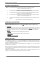
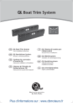
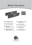
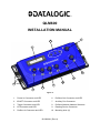
QLM600 INSTALLATION MANUAL 7 8 9 6 5 4 10 3 2 1 Figure A 1 Power In Connector and LED 6 Profibus Out Connector and LED 2 ID-NET Connector and LED 7 Auxiliary Port Connector 3 Trigger Connector and LED 8 Profibus Network Address Selectors 4 I/O Connector and LED 9 Reading Device Connector 5 Profibus In Connector and LED 10 Mounting slots (6) 821000281 (Rev.A) QLM600 INSTALLATION MANUAL UPDATES AVAILABILITY UK/US The latest documentation updates for this product are available on Internet. Log on to: www.automation.datalogic.com I Su Internet sono disponibili le versioni aggiornate di documentazione di questo prodotto. Collegarsi a: www.automation.datalogic.com F Les versions mises à jour de documentation de ce produit sont disponibles sur Internet. Cliquez sur : www.automation.datalogic.com D Im Internet finden Sie die aktuellsten Versionen der Dokumentation von diesem Produkt. Adresse : www.automation.datalogic.com E En Internet están disponibles las versiones actualizadas de la documentación de este producto. Dirección Internet : www.automation.datalogic.com SERVICES AND SUPPORT Datalogic provides several services as well as technical support through its website. Log on to www.automation.datalogic.com and click on the links indicated for further information including: PRODUCTS Search through the links to arrive at your product page which describes specific Info, Features, Applications, Models, Accessories, and Downloads including the Genius™ utility program, which allows device configuration using a PC. It provides RS232 and Ethernet interface configuration. SERVICE - Overview - Warranty Extensions and Maintenance Agreements - Sales Network- Listing of Subsidiaries, Repair Centers, Partners - Helpdesk - Material Return Authorization LEGAL NOTICES © 2011 Datalogic Automation S.r.l. ALL RIGHTS RESERVED. Protected to the fullest extent under U.S. and international laws. Copying, or altering of this document is prohibited without express written consent from Datalogic Automation S.r.l. Datalogic and the Datalogic logo are registered trademarks of Datalogic S.p.A. in many countries, including the U.S.A. and the E.U. ID-NET, and Genius are trademarks of Datalogic Automation S.r.l. All other brand and product names mentioned herein are for identification purposes only and may be trademarks or registered trademarks of their respective owners. Datalogic shall not be liable for technical or editorial errors or omissions contained herein, nor for incidental or consequential damages resulting from the use of this material. 2 QLM600 INSTALLATION MANUAL DESCRIPTION The QLM600 Profibus Gateway is an active connection module which can be used in Standalone or ID-NET™ Master Multidata, or Master Synchronized layouts. It provides a fast and efficient way to cable both a Profibus DPV1 network and an ID-NET™ network using standard cables. It provides separate M12 connectors for Power Supply, Profibus Communication, ID-NET™ Network, External Trigger, Digital I/O and Aux RS232 Communication for configuration of the reading device. Host communication is provided through the integrated Profibus DPV1 circuitry which connects internally to the reader's Main serial interface (RS232). ID-NET™ network and power supply signals are sent out to the next connected device (IDNET™ Slave), by means of a dedicated M12 connector. However there is no ID-NET™ network input connector and therefore the QLM600 cannot be used as an ID-NET™ Slave. The reading device is connected to the QLM600 through a standard 25-pin D-sub connector and must communicate only in RS232. When correctly connected to a Profibus network, the QLM600 acts as a DPV1 slave. Three rotary switches allow easy manual Profibus Network Addressing selection. The following accessories make system cabling easy: CBL-1487 M12/5P/FEMALE A-Code connector for PWR-IN, to build the Power Supply connection. FMC600 M12 8P M. A-Code QLM-I/O, to build the I/O connections. CAB-AUX03, to connect the Gateway to a PC to configure the connected reading device. CBL-1480-xx, to build the ID-NET network connections. QLM600 has integrated on-board backup memory and therefore supports Backup and Restore procedures for the connected device and relative ID-NET™ network (if used). See the device's Backup and Restore procedure in the Help On Line. This procedure can also be performed using programming barcodes. See the 2KN-4K Family Scanner Setup Procedure Using Programming Barcodes document on the CD-ROM. For full compatibility with QLM600, the 2KN-4K Family Scanner must have software package 007 or later. NOTE 3 QLM600 INSTALLATION MANUAL PACKAGE CONTENTS Verify that the QLM600 and all the parts supplied with the equipment are present and intact when opening the packaging; the list of parts includes: QLM600 Gateway This Installation Manual Mounting screws and washers (2) M12 protection caps (3) pre-mounted Figure 1 - Package Contents ACCESSORIES The following accessories are available on request for the QLM600: Name Description Field Mountable Connectors CBL-1487 PWR-IN CONNECTOR M12 5P F. A-Coded FMC600 QLM-I/O CONNECTOR M12 8P M. A-Coded 970101063 93ACC0040 Cables CAB-AUX03 CBL-1480-01 CBL-1480-02 93A051385 970101021 970101022 SERIAL CABLE M12/3P MALE/DB9 3M ID-NET Out/In THIN M12/5P MALE/FEMALE 1M ID-NET Out/In THIN M12/5P MALE/FEMALE 2M Part Number SUPPORTED READING DEVICES The QLM600 can be directly connected to all of the following readers through the 25-pin connector illustrated in Figure A. DS2100N 4 Linear Scanners DS2400N DS4800 Matrix 210™ 2D Readers Matrix 410™ Matrix 450™ QLM600 INSTALLATION MANUAL MECHANICAL INSTALLATION QLM600 can be mounted to various surfaces using the two M5x20 screw and washers included in the package: The M5x20 screws can be used to mount the QLM600 to metallic/plastic surfaces already prepared with M5 threaded holes. QLM600 can also be mounted to a Bosch Frame using the two M5x20 screws included in the package, plus two specific commercial T-nuts (for example the Bosch Rexroth T-nut 10 M5, cod. 3 842 530 283). Mounting to other surfaces, such as concrete walls or metallic panels, requires appropriate user-supplied parts (screws, screw anchors, nuts, etc). 40 [1.56] The diagram below gives the overall dimensions of the QLM600 and shows the mounting through-holes. 200 [7.88] 9.5 [0.37] 5.5 n° 2 [0.22] = [in] = 53.5 [2.11] mm Mounting Slots (6) = 81 [3.18] = 188 [7.40] 5.5 n° 4 [0.22] Figure 2 - Overall Dimensions 5 QLM600 INSTALLATION MANUAL ELECTRICAL CONNECTIONS CONNECTORS PWR-IN (Power In) M12 5P Male (A-coded) Pin Function 1 Vdc 2 nc 3 GND 4 nc 5 nc ID-NET (Out) M12 5P Female (A-coded) Pin Function 1 Shield 2 Vdc 3 GND 4 ID+ 5 ID- 4 5 3 1 2 TRG (Trigger) M12 4P Female (A-coded) Pin Function 1 +V (I/O) 2 nc 3 -V (I/O) 4 I1+ (trigger) 4 2 1 4 5 3 1 2 AUX M12 5P Female (B-coded) Pin Function 1 nc 2 RXA 3 GND 4 TXA 5 nc 4 4 2 6 5 7 8 4 1 3 PB-OUT (Profibus Out) M12 5P Female (B-coded) Pin Function 1 +5V Bus 2 A Line (-) 3 GND Bus 4 B Line (+) 5 Shield 1 2 1 2 1 25 Pin 1, shell, 2 3 4 5 6 7 8 9 Function Reader Chassis TXM RXM RTSM CTSM I2A GND O1+ nc 5 3 3 13 2 4 5 Reader 25P D-Sub Female 6 5 1 I/O M12 8P Female (A-coded) Pin Function 1 +V (I/O) 2 -V (I/O) 3 I2+ (input) 4 nc 5 O1+ (output) 6 O1- (output) 7 O2+ (output) 8 O2- (output) 3 PB-IN (Profibus In) M12 5P Male (B-coded) Pin Function 1 +5V Bus 2 A Line (-) 3 GND Bus 4 B Line (+) 5 Shield 3 14 Pin Function Pin Function 10 11 12 13 14 15 16 17 I2B O2+ O2Vdc nc nc nc nc 18 19 20 21 22 23 24 25 I1A GND RXA TXA O1ID+ IDGND QLM600 INSTALLATION MANUAL PWR-IN Input power must only be supplied to the QLM600 at the PWR-IN connector; from there it is internally distributed to the connected reading device, the ID-NET™ network and all the I/O devices. You can use the CBL-1487 connector and follow the pinout above to build your own Power Supply connector cable. The LED placed below the PWR-IN connector, signals the presence of input Power. If the polarity is correct, the LED is blue; if the polarity is reversed, the LED is red; if no power is supplied, the LED is off. CAUTION The QLM600 and the connected reader are protected from polarity inversion through the PWR-IN connector, but this is not true for the other devices connected to the ID-NET™ Network, TRG and I/O connectors (i.e. external trigger, encoder, etc.). Check the correct Power Supply polarity looking at the PWR-IN LED before connecting other devices to the QLM600. The power supply must be between 10 and 30 Vdc only. Voltage Drop and Max Distributed Current Calculations For correct ID-NET™ network management, the maximum number of readers which can propagate power through the QLs must be calculated so that max distributed current is not exceeded (4.0 A), and so voltage drop doesn't affect reader functioning. This is done according to the following formula: Voltage Drop = (Max Reader Current x Number of readers) x (Resistance per Meter per wire* x Cable length in Meters) * the resistance calculation must include both wires (Vdc and GND). Example: An ID-NET™ network is composed of 4 DS2100N readers. Three 2 meter ThinNet cables are used to connect the readers, which have Cable Resistance = 0.058 Ohms per meter per wire. The network power is 24 Vdc. (0.125 A x 4 readers) x [(0.058 x 2) x 6 meters] = 0.348 Vdc voltage drop 24 Vdc - 0.348 = 23.65 Vdc at reader number 4 (worst case) Integrate a sufficient number of QL200s to resupply network power. ID-NET ID-NET is a 5-pin Female A-Coded M12 connector. It is used to carry out the network signals and the power supply for the ID-NET™ Network. Pins 2 and 3 on the ID-NET connector carry the same power supply lines present on pins 1 and 3 of the PWR-IN connector; however power must only be supplied to the QLM600 through the PWR-IN connector. 7 QLM600 INSTALLATION MANUAL In an ID-NET™ network, the reading device connected to the QLM600 must be configured as an ID-NET™ Master; to facilitate the network setup, the QLM600 already provides an internal bus termination resistor (the Master is the first device of the chain). When using QLM600 in an ID-NET™ network application, the network termination cap must be connected to the last device of the chain. CAUTION TRG CONNECTOR TRG is a 4-pin Female A-Coded M12 connector. You can connect a PNP photocell to it, which will act as an External Trigger (Input 1) for the connected reading device. When the Trigger is activated, the LED below the TRG connector is yellow. See the Technical Features table for electrical specifications. NOTE Pins 1 +V (I/O) and 3 -V (I/O) are derived from Vdc and GND and are useful for supplying the external trigger through the QLM600 power source, however pins 1 and 3 of the TRG connector must not be used as power supply inputs to the QLM600. I/O CONNECTOR I/O is an 8-pin Female A-Coded M12 connector. It carry the signals for the other I/O signals (Input 2 / Secondary Trigger, Output 1 and Output 2) as shown below. If Input 2 is used as a Secondary Trigger, the photocell must be a PNP device. Note that all these signals are relative to the connected reader. When the Input 2 (Secondary Trigger) is activated, the LED below the I/O connector is yellow. When the Output 1 signal is activated, the LED below the I/O connector is red. When the Output 2 signal is activated, the LED below the I/O connector is green. See the Technical Features table for electrical specifications. NOTE Pins 1 +V (I/O) and 2 -V (I/O) are derived from Vdc and GND and are useful for supplying the I/O devices through the QLM600 power source, however pins 1 and 2 of the I/O connector must not be used as power supply inputs to the QLM600. To reduce electromagnetic interference use a shielded cable for I/O connections. NOTE 8 QLM600 INSTALLATION MANUAL PB-IN CONNECTOR PB-IN is a 5-pin Male B-Coded M12 connector. It is used to connect the QLM600 to a Profibus network in a Daisy Chain bus topology. PB-OUT CONNECTOR PB-OUT is a 5-pin Female B-Coded M12 connector. It is used to connect the QLM600 to a Profibus network in a Daisy Chain bus topology. You should connect a Profibus bus termination male plug to this connector only if the QLM600 is the last slave in the Profibus chain. AUX CONNECTOR AUX is a 5-pin Female B-Coded M12 connector. It is used to connect the reading device connected to the QLM600 to a configuration program on a PC. For example for the DS2100N/2400N/4800 barcode readers you should use the Genius™ configuration tool. You can use the CAB-AUX 03 accessory cable to easily connect the QLM600 to a PC DB9 serial port. SYSTEM WIRING/CABLING The connection and wiring procedure for QLM600 is described as follows: 1) Be sure that all the QLM600 M12 connectors are free (not connected). 2) Build your power supply cable using the CBL-1487 accessory connector following the pinout shown in the Connectors paragraph (PWR-IN Connector). Use an adequate cable/wire diameter, according to the total current required for the application (QLM600, connected reader, trigger, other I/O devices, ID-NET™ Network components). 3) Connect the power supply cable to the QLM600 (with no other devices connected) and apply power checking that the polarity is correct: the blue LEDs below both PWR-IN and ID-NET (out) M12 connectors must be turned on. If instead the red LEDs are turned on, the polarity is incorrect; switch off the power and check the cable. Correct the situation so that the power supply polarity is correct. 4) When the connection to the power supply is correct switch off the power. 5) Connect the reading device to the 25-pin connector. 6) If your application requires it, connect a PNP photocell to the TRG connector. 7) If your application involves other I/O devices you can build your I/O cable using the FMC600 accessory and following the pinout shown in the Connectors paragraph (I/O Connector); next connect your cable to the I/O connector. 8) If an ID-NET™ network is required in your application, build the network using the proper Datalogic Automation accessory cables, connectors and termination cap. See the Typical Layouts for example. 9 QLM600 INSTALLATION MANUAL 9) Connect the QLM600 to the Profibus Network using proper Profibus cables; if the QLM600 is the last slave of the chain you should put a proper bus terminator, typically in the PB-OUT connector. 10) Preset the Node Address of the QLM600, as shown in the Profibus Network Address Selectors paragraph. 11) Switch on the power supply; after a while (the system needs some seconds to boot) and if the Profibus Master is ready and has correctly recognized the QLM600 slave, both the green LEDs below both PB-IN and ID-NET (out) M12 connectors will be turned on. 12) If you need to configure the reading device, connect the AUX port through the CABAUX03 accessory cable to a PC and run the configuration program (i.e. Genius™). Now the system is ready to operate. To avoid electromagnetic interference connect the QLM600 housing to a good earth ground. NOTE PROFIBUS NETWORK ADDRESS SELECTORS The QLM600 has three embedded rotary switches allowing easy manual selection of the Profibus Network Node Address. The valid selection range for the Profibus Node Address is from 000 to 126. Address selections outside of this range are not accepted. Address 126 is a special address which allows the Profibus Master, through software, to set the node address in the range from 000 to 125. Using a small screwdriver, set the three rotary switches manually to the desired Profibus Node Address (reading from left to right). Figure 3 shows the address 107. Hundreds Tens Units Figure 3 – Profibus Network Address Selectors 10 QLM600 INSTALLATION MANUAL INDICATOR LEDS There are six Indicator LEDs which signal power, I/O and Profibus communication activity and are visible below the M12 connectors (excluding AUX). PWR-IN / ID-NET The Power LEDs are blue when power is correctly applied to the QLM600. These LEDs are red if power polarity is incorrect. In this case the QLM600 and the connected reading device are protected. If external I/O devices are powered through QLM600 (connected to +V I/O and -V I/O), they are not protected from polarity inversion. CAUTION TRG The Trigger LED is yellow and it is on when the Trigger (presence sensor) photocell is activated. I/O The I/O LEDs reflect the activity of the supplemental I/O devices connected to the reading device through the QLM600. The Input 2 LED is yellow and it is on when the supplemental photocell is activated. The Output 1 LED is red and it is on when the reading device Output 1 is activated. The Output 2 LED is green and it is on when the reading device Output 2 is activated. PB-IN The LED below PB-IN acts as the ‘Profibus Network Operation Mode’ indicator. It is driven according to the following table. Operation Mode LED Off Not on-line, No power Green On-line, data exchange Flashing Green On-line, clear Flashing Red (1 flash) Parameterization error Flashing Red (2 flashes) Profibus configuration error PB-OUT The LED below PB-OUT acts as the ‘Module Status’ indicator. It is driven according to the following table. Off Green Flashing Green Red Module Status LED No power or not initialized Initialized Initialized, diagnostic event(s) present Exception error 11 QLM600 INSTALLATION MANUAL TYPICAL LAYOUTS The following figure shows the general system layout. Reader Configuration PC Auxiliary Interface Reading Device Profibus Terminator or to next Profibus Slave QLM600 Power from previous Profibus Slave ID-NET™ Trigger or I/O from Profibus Master (Host) Figure 4 – General System Layout The dotted lines in the figure refer to optional hardware configurations. The general system layout allows the QLM600 Profibus Gateway to connect one of the compatible serial reading devices (2KN, 4K Scanner, Matrix 410™, etc.), collect its information and send it to a Profibus Host. The Profibus network from the Host is connected to the QLM600 PB-IN interface. PB-OUT connects either to the next Profibus Slave node or, if the last node in the chain, to a Profibus terminator. The reading device connects to the 25-pin connector and must communicate only in RS232. The ID-NET interface allows a network of ID-NET Slaves to be connected through the QLM600 to the reading device which acts as the ID-NET Master. The reading device auxiliary interface signals are available on the AUX connector which can be quickly connected to a portable PC for reader configuration. 12 QLM600 INSTALLATION MANUAL The following diagrams are examples showing layout connections and are not intended to represent power limits, which instead, depend on each specific application. See "Voltage Drop and Max Distributed Current Calculations". ID-NET™ Slave CAB-AUX04 CAB-AUX04 4 5 CAB-AUX03 5 QL300 GOOD STATUS READY TRIGGER COM Profibus Terminator 3 6 QLM600 INTERFACE LEARN TEST QL300 DS4800 Matrix 410™ SETUP XPRESS CBL-1490 Configuration PC 4 5 DS2100N 7 Profibus Slave Node ID-NET™ Master ID-NET™ Slave 3 3 2 4 6 CBL-1480-xx 2 CBL-1480-xx or to next Profibus Slave 1 Profibus Master (Host) ID-NET™ Multidata Network - DS4800 Master with QLM600 + mixed Slaves with QL300s QL100 INTERFACE LEARN TEST STATUS READY GOOD TRIGGER COM Profibus Slave Node ID-NET™ Master SETUP XPRESS ID-NET™ Slaves READY SETUP LEARN TEST GOOD TRIGGER COM STATUS XPRESS INTERFACE QL100 Profibus Terminator or QLM600 3 5 CAB-AUX03 CBL-1480-xx Configuration PC 7 CBL-1490 6 to next Profibus Slave 2 1 2 CBL-1480-xx 6 4 Profibus Master (Host) ID-NET™ Synchronized Network - DS2100N Master with QLM600 + DS2100N Slaves with QL100s Input Power Profibus Interface External Trigger (for On-Line Mode) External Digital I/O Devices Aux port for Reader Configuration ID-NET™ Network ID-NET Terminator The ID-NET network must be terminated inserting an ID-NET terminator into the last QL in the network. ID-NET on the QLM600 is internally terminated. NOTE 13 QLM600 INSTALLATION MANUAL TECHNICAL FEATURES ELECTRICAL FEATURES Supply Voltage Consumption Maximum Distributed Current Allowed ID-NET Limited Current Consumption QLM600 + reading device Trigger + I/O device 10 to 30 Vdc 0.3 - 0.2 A 4.0 A max 1.85 A max 0.75 A max (see related device manuals) Inputs: Input1 (TRG), Input 2 Voltage Current Consumption Outputs: Output 1, Output 2 VCE Collector Current VCE Saturation Power Dissipation COMMUNICATION INTERFACES Host Interface Auxiliary ID-NET™ Communication Protocols USER INTERFACE LED Indicators PHYSICAL FEATURES Mechanical Dimensions Weight ENVIRONMENTAL FEATURES Operating Temperature Storage Temperature Humidity max. Vibration Resistance EN 60068-2-6 Bump Resistance EN 60068-2-29 Protection Class EN 60529 Optocoupled 30 Vdc max. 12 mA max. Optocoupled 30 Vdc max. 40 mA continuous max.; 130 mA pulsed max. 1V max. @ 10 mA 80 mW max. @ 45 °C (ambient temperature) Profibus DPV1 (up to 12 Mbit/s) RS232 up to 115.2 kbit/s RS485 Half Duplex up to 1 Mbit/s Datalogic Application Driver (DAD Driver) Power On/Polarity Error (blue/red), Trigger (yellow), IN2 (yellow), OUT1 (red), OUT2 (green), Profibus Network Op. Mode (green/red), Profibus Module Status (green/red) 200 x 81 x 40 mm (7.9 x 3.2 x 1.6 in.) 520 g. (18.34 oz.) 0° to 50 C (+32° to 122 °F) -20° to 70 C (-4° to 158 °F) 90% non condensing 14 mm @ 2 to 10 Hz; 1.5 mm @ 13 to 55 Hz; 2 g @ 70 to 200 Hz; 2 hours on each axis 30 g; 6 ms; 5000 shocks on each axis IP65 * The features given are typical at a 25 C ambient temperature (if not otherwise indicated). * when all the M12 connectors and reading device are correctly connected (or closed with a proper cap). 14 QLM600 INSTALLATION MANUAL COMPLIANCE POWER SUPPLY This product is intended to be installed by Qualified Personnel only. This device is intended to be supplied by a UL Listed or CSA Certified Power Unit with Class 2 or LPS power source. CAUTION Total power consumption is given by adding the QLM600 power consumption to that of all the devices powered through the QLM600 (reading device, P.S., I/O). Refer to the manual of the connected devices for details about minimum/maximum supply voltage and power consumption. CE COMPLIANCE Warning: This is a Class A product. In a domestic environment this product may cause radio interference in which case the user may be required to take adequate measures. FCC COMPLIANCE Modifications or changes to this equipment without the expressed written approval of Datalogic could void the authority to use the equipment. This device complies with PART 15 of the FCC Rules. Operation is subject to the following two conditions: (1) This device may not cause harmful interference, and (2) this device must accept any interference received, including interference which may cause undesired operation. This equipment has been tested and found to comply with the limits for a Class A digital device, pursuant to part 15 of the FCC Rules. These limits are designed to provide reasonable protection against harmful interference when the equipment is operated in a commercial environment. This equipment generates, uses, and can radiate radio frequency energy and, if not installed and used in accordance with the instruction manual, may cause harmful interference to radio communications. Operation of this equipment in a residential area is likely to cause harmful interference in which case the user will be required to correct the interference at his own expense. 15 DECLARATION OF CONFORMITY EC-128 Rev.: 2 Pag.: 1 di 1 Datalogic Automation S.r.l. Via Lavino 265 40050 Monte San Pietro Bologna - Italy www.automation.datalogic.com declares that the QLxxx and QLMxxx; Connection module and all its models are in conformity with the requirements of the European Council Directives listed below: 2004 / 108 / EC EMC Directive ______________________________________________ This Declaration is based upon compliance of the products to the following standards: EN 55022 ( CLASS A ITE ), DECEMBER 2010: INFORMATION TECHNOLOGY EQUIPMENT RADIO DISTURBANCE CHARACTERISTICS LIMITS AND METHODS OF MEASUREMENTS EN 61000-6-2, SEPTEMBER 2005: ELECTROMAGNETIC COMPATIBILITY (EMC) PART 6-2: GENERIC STANDARDS - IMMUNITY FOR INDUSTRIAL ENVIRONMENTS Monte San Pietro, January 20th , 2012 Paolo Morselli Quality Manager UNI EN ISO 14001