1
PV Inverter
SUNNY BOY 5000-US / 6000-US / 7000-US / 8000-US
Installation Manual
SB50US-80US-IA-en-37 | TBUS-SB50_60_70US | Version 3.7
CA
US
SMA America, LLC
Legal Restrictions
Copyright © 2011 SMA America, LLC. All rights reserved.
No part of this document may be reproduced, stored in a retrieval system, or transmitted, in any form
or by any means, electronic, mechanical, photographic, magnetic or otherwise, without the prior
written permission of SMA America, LLC.
Neither SMA America, LLC nor SMA Solar Technology Canada Inc. makes representations, express
or implied, with respect to this documentation or any of the equipment and/or software it may
describe, including (with no limitation) any implied warranties of utility, merchantability, or fitness for
any particular purpose. All such warranties are expressly disclaimed. Neither SMA America, LLC nor
its distributors or dealers nor SMA Solar Technology Canada Inc. nor its distributors or dealers shall
be liable for any indirect, incidental, or consequential damages under any circumstances.
(The exclusion of implied warranties may not apply in all cases under some statutes, and thus the
above exclusion may not apply.)
Specifications are subject to change without notice. Every attempt has been made to make this
document complete, accurate and up-to-date. Readers are cautioned, however, that
SMA America, LLC and SMA Solar Technology Canada Inc. reserve the right to make changes
without notice and shall not be responsible for any damages, including indirect, incidental or
consequential damages, caused by reliance on the material presented, including, but not limited to,
omissions, typographical errors, arithmetical errors or listing errors in the content material.
All trademarks are recognized even if these are not marked separately. Missing designations do not
mean that a product or brand is not a registered trademark.
The Bluetooth® word mark and logos are registered trademarks owned by Bluetooth SIG, Inc. and
any use of such marks by SMA America, LLC and SMA Solar Technology Canada Inc. is under
license.
SMA America, LLC
3801 N. Havana Street
Denver, CO 80239 U.S.A.
SMA Solar Technology Canada Inc.
2425 Matheson Blvd. E, 8th Floor
Mississauga, ON L4W 5K5, Canada
Installation Manual
SB50US-80US-IA-en-37
3
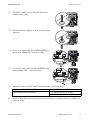
Important Safety Instructions
SMA America, LLC
IMPORTANT SAFETY INSTRUCTIONS
SAVE THESE INSTRUCTIONS
This manual contains important instructions for Sunny Boy inverter, that must be followed during
installation and maintenance of the inverter.
The Sunny Boy is designed and tested according to international safety requirements, but as with all
electrical and electronic equipment, certain precautions must be observed when installing and/or
operating the Sunny Boy. To reduce the risk of personal injury and to ensure the safe installation and
operation of the Sunny Boy, you must carefully read and follow all instructions, cautions and warnings
in this installation guide.
Warnings in this document
A warning describes a hazard to equipment or personnel. It calls attention to a procedure or practice,
which, if not correctly performed or adhered to, could result in damage to or destruction of part or all
of the SMA equipment and/or other equipment connected to the SMA equipment or personal injury.
DANGER
DANGER indicates a hazardous situation which, if not avoided, will result in death or
serious injury.
WARNING
WARNING indicates a hazardous situation which, if not avoided, could result in death or
serious injury.
CAUTION
CAUTION indicates a hazardous situation which, if not avoided, could result in minor or
moderate injury.
NOTICE
NOTICE is used to address practices not related to personal injury.
4
SB50US-80US-IA-en-37
Installation Manual
SMA America, LLC
Important Safety Instructions
Other symbols in this document
In addition to the safety and hazard symbols described on the previous pages, the following symbol
is also used in this installation guide:
Information
This symbol accompanies notes that call attention to supplementary information that you
must know and use to ensure optimal operation of the system.
Markings on this product
The following symbols are used as product markings with the following meanings.
Warning regarding dangerous voltage
The product works with high voltages. All work on the product must only be performed
as described in the documentation of the product.
Beware of hot surface
The product can become hot during operation. Do not touch the product during
operation.
Observe the operating instructions
Read the documentation of the product before working on it. Follow all safety
precautions and instructions as described in the documentation.
Evaluated to the requirements of the Underwriters Laboratories Standard for Safety for
Inverters, Converters, Controllers and Interconnection System Equipment for Use With
Distributed Energy Resources, UL 1741.
Installation Manual
SB50US-80US-IA-en-37
5
General Warnings
SMA America, LLC
General warnings
General warnings
All electrical installations must be done in accordance with the local and
National Electrical Code® ANSI/NFPA 70 or the Canadian Electrical Code®
CSA C22.1. This document does not and is not intended to replace any local, state,
provincial, federal or national laws, regulation or codes applicable to the installation and
use of the inverter, including without limitation applicable electrical safety codes. All
installations must conform with the laws, regulations, codes and standards applicable in
the jurisdiction of installation. SMA assumes no responsibility for the compliance or
noncompliance with such laws or codes in connection with the installation of the inverter.
The Sunny Boy contains no user-serviceable parts except for the fans on the bottom of the
enclosure and the filters behind the fans as well as the handle covers on the sides of the
unit. For all repair and maintenance, always return the unit to an authorized SMA Service
Center.
Before installing or using the Sunny Boy, read all of the instructions, cautions, and warnings
on the Sunny Boy in this installation guide.
Before connecting the Sunny Boy to the electrical utility grid, contact the local utility
company. This connection must be made only by qualified personnel.
Wiring of the Sunny Boy must be made by qualified personnel only.
6
SB50US-80US-IA-en-37
Installation Manual
SMA America, LLC
Table of Contents
Table of Contents
1
1.1
1.2
1.3
1.4
1.5
Information on this Manual. . . . . . . . . . . . . . . . . . . . . . . . 11
Validity . . . . . . . . . . . . . . . . . . . . . . . . . . . . . . . . . . . . . . . . . . . 11
Target Group . . . . . . . . . . . . . . . . . . . . . . . . . . . . . . . . . . . . . . 11
Storing the Documentation . . . . . . . . . . . . . . . . . . . . . . . . . . . . 11
Additional Information . . . . . . . . . . . . . . . . . . . . . . . . . . . . . . . 11
Nomenclature . . . . . . . . . . . . . . . . . . . . . . . . . . . . . . . . . . . . . . 11
2
2.1
2.2
2.3
Safety . . . . . . . . . . . . . . . . . . . . . . . . . . . . . . . . . . . . . . . . . 14
Intended Use. . . . . . . . . . . . . . . . . . . . . . . . . . . . . . . . . . . . . . . 14
Safety Instructions . . . . . . . . . . . . . . . . . . . . . . . . . . . . . . . . . . . 16
Installation Overview . . . . . . . . . . . . . . . . . . . . . . . . . . . . . . . . 17
3
3.1
Unpacking and Inspection. . . . . . . . . . . . . . . . . . . . . . . . . 18
Scope of Delivery . . . . . . . . . . . . . . . . . . . . . . . . . . . . . . . . . . . 18
4
4.1
4.2
4.3
4.4
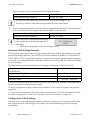
AC Voltage Configuration . . . . . . . . . . . . . . . . . . . . . . . . . 19
Opening the Sunny Boy . . . . . . . . . . . . . . . . . . . . . . . . . . . . . . 19
Locating Internal Component Parts . . . . . . . . . . . . . . . . . . . . . . 20
AC Voltage Configuration . . . . . . . . . . . . . . . . . . . . . . . . . . . . 21
Jumper for System Configuration . . . . . . . . . . . . . . . . . . . . . . . 24
5
5.1
5.2
5.3
Assembly. . . . . . . . . . . . . . . . . . . . . . . . . . . . . . . . . . . . . . . 26
Safety . . . . . . . . . . . . . . . . . . . . . . . . . . . . . . . . . . . . . . . . . . . . 26
Requirements for the Mounting Location. . . . . . . . . . . . . . . . . . 27
Mounting with Wall Mounting Bracket. . . . . . . . . . . . . . . . . . . 29
5.3.1
Possibilities for Mounting the Wall Mounting Bracket. . . . . . . . . . . . . . . . . . 31
5.3.2
Mounting the Wall Mounting Bracket. . . . . . . . . . . . . . . . . . . . . . . . . . . . . . 32
5.4
Mounting the DC Disconnect . . . . . . . . . . . . . . . . . . . . . . . . . . 32
5.4.1
Mounting the DC disconnect. . . . . . . . . . . . . . . . . . . . . . . . . . . . . . . . . . . . . 34
5.4.2
Mounting the Sunny Boy on a Wall Mounting Bracket . . . . . . . . . . . . . . . . 35
Installation Manual
SB50US-80US-IA-en-37
7
Table of Contents
SMA America, LLC
6
6.1
6.2
Electrical Connection . . . . . . . . . . . . . . . . . . . . . . . . . . . . . 36
Connection Area of the Sunny Boy. . . . . . . . . . . . . . . . . . . . . . 37
Sunny Boy Circuit Diagrams . . . . . . . . . . . . . . . . . . . . . . . . . . . 38
6.2.1
Wiring with DC disconnect . . . . . . . . . . . . . . . . . . . . . . . . . . . . . . . . . . . . . . 39
6.3
6.4
6.5
Opening the Sunny Boy . . . . . . . . . . . . . . . . . . . . . . . . . . . . . . 40
Opening the DC Disconnect . . . . . . . . . . . . . . . . . . . . . . . . . . . 41
AC Connection . . . . . . . . . . . . . . . . . . . . . . . . . . . . . . . . . . . . . 42
6.5.1
6.5.2
AC Connection Requirements . . . . . . . . . . . . . . . . . . . . . . . . . . . . . . . . . . . . 42
AC Connection in the DC Disconnect . . . . . . . . . . . . . . . . . . . . . . . . . . . . . . 43
6.5.3
Connecting the AC Cables in the Sunny Boy . . . . . . . . . . . . . . . . . . . . . . . . 44
6.6
DC Connection . . . . . . . . . . . . . . . . . . . . . . . . . . . . . . . . . . . . . 46
6.6.1
DC Connection Requirements . . . . . . . . . . . . . . . . . . . . . . . . . . . . . . . . . . . . 47
6.6.2
DC Input Grounding . . . . . . . . . . . . . . . . . . . . . . . . . . . . . . . . . . . . . . . . . . . 48
6.6.3
Connecting the DC Cables in the DC disconnect . . . . . . . . . . . . . . . . . . . . . 49
6.6.4
DC Connection with Additional DC Distribution . . . . . . . . . . . . . . . . . . . . . . 54
6.7
6.8
6.9
Communication. . . . . . . . . . . . . . . . . . . . . . . . . . . . . . . . . . . . . 55
Closing the Sunny Boy . . . . . . . . . . . . . . . . . . . . . . . . . . . . . . . 56
Closing the DC Disconnect . . . . . . . . . . . . . . . . . . . . . . . . . . . . 57
7
7.1
7.2
Commissioning . . . . . . . . . . . . . . . . . . . . . . . . . . . . . . . . . . 58
Switching On the Sunny Boy . . . . . . . . . . . . . . . . . . . . . . . . . . 58
The Sunny Boy Does Not Resume Operation. . . . . . . . . . . . . . 59
8
8.1
8.2
8.3
8.4
8.5
Displays and Messages. . . . . . . . . . . . . . . . . . . . . . . . . . . 62
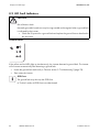
LED Operation Indicators . . . . . . . . . . . . . . . . . . . . . . . . . . . . . 63
LED Fault Indicators. . . . . . . . . . . . . . . . . . . . . . . . . . . . . . . . . . 66
Status Messages on the LCD Display . . . . . . . . . . . . . . . . . . . . 70
Setting the Display Language . . . . . . . . . . . . . . . . . . . . . . . . . . 72
Measuring Channels and Parameters. . . . . . . . . . . . . . . . . . . . 72
8.5.1
Measurement Channels . . . . . . . . . . . . . . . . . . . . . . . . . . . . . . . . . . . . . . . . 73
8.5.2
Operating Mode. . . . . . . . . . . . . . . . . . . . . . . . . . . . . . . . . . . . . . . . . . . . . . 74
8
SB50US-80US-IA-en-37
Installation Manual
SMA America, LLC
Table of Contents
8.5.3
Operating Parameters of the Sunny Boy. . . . . . . . . . . . . . . . . . . . . . . . . . . . 74
8.5.4
Operating Parameters of the Sunny Boy. . . . . . . . . . . . . . . . . . . . . . . . . . . . 74
8.5.5
Fixed Operating Parameters of the Sunny Boy . . . . . . . . . . . . . . . . . . . . . . . 77
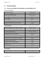
9
9.1
9.2
Troubleshooting . . . . . . . . . . . . . . . . . . . . . . . . . . . . . . . . . 78
General. . . . . . . . . . . . . . . . . . . . . . . . . . . . . . . . . . . . . . . . . . . 78
Error Messages. . . . . . . . . . . . . . . . . . . . . . . . . . . . . . . . . . . . . 78
10
Maintenance. . . . . . . . . . . . . . . . . . . . . . . . . . . . . . . . . . . . 81
10.1
10.2
10.3
10.4
10.5
Cleaning the Fans . . . . . . . . . . . . . . . . . . . . . . . . . . . . . . . . . . . 81
Cleaning the Handle Covers . . . . . . . . . . . . . . . . . . . . . . . . . . 83
Checking the DC Disconnect . . . . . . . . . . . . . . . . . . . . . . . . . . 83
Fan Test. . . . . . . . . . . . . . . . . . . . . . . . . . . . . . . . . . . . . . . . . . . 84
Exchanging the Fuses . . . . . . . . . . . . . . . . . . . . . . . . . . . . . . . . 85
10.5.1
Exchanging the GFDI Fuse within the Sunny Boy . . . . . . . . . . . . . . . . . . . . . 86
10.5.2
Exchanging PV String Fuses within the DC disconnect . . . . . . . . . . . . . . . . . 86
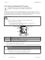
10.6
Testing and Replacing the DC Varistors . . . . . . . . . . . . . . . . . . 88
11
11.1
11.2
11.3
11.4
11.5
11.6
11.7
Technical Data . . . . . . . . . . . . . . . . . . . . . . . . . . . . . . . . . . 91
Sunny Boy 5000-US (SB 5000US and SB 5000US-12) . . . . . 91
Sunny Boy 6000-US (SB 6000US and SB 6000US-12) . . . . . 93
Sunny Boy SB 7000-US (SB 7000US and SB 7000US-12) . . 95
Sunny Boy SB 8000-US (SB 8000US and SB 8000US-12) . . 97
DC Disconnect . . . . . . . . . . . . . . . . . . . . . . . . . . . . . . . . . . . . . 99
Trip Limits/Trip Times. . . . . . . . . . . . . . . . . . . . . . . . . . . . . . . . 100
Torque Values and Cable Sizes . . . . . . . . . . . . . . . . . . . . . . . 101
12
Spare Parts and Accessories . . . . . . . . . . . . . . . . . . . . . . 101
13
Compliance Information . . . . . . . . . . . . . . . . . . . . . . . . . 102
14
Contact . . . . . . . . . . . . . . . . . . . . . . . . . . . . . . . . . . . . . . . 103
Installation Manual
SB50US-80US-IA-en-37
9
SMA America, LLC
Information on this Manual
1 Information on this Manual
1.1 Validity
This guide describes the mounting, installation, commissioning and maintenance of the following SMA
inverters:
• Sunny Boy 5000-US (SB 5000US and SB 5000US-12)
• Sunny Boy 6000-US (SB 6000US and SB 6000US-12)
• Sunny Boy 7000-US (SB 7000US and SB 7000US-12)
• Sunny Boy 8000-US (SB 8000US and SB 8000US-12)
This guide does not contain any information on the devices that are connected to the Sunny Boy.
Information concerning the connected devices is available from the manufacturers of the devices.
1.2 Target Group
This manual is for qualified personnel. Qualified personnel have received training and have
demonstrated skills and knowledge in the construction and operation of this device. Qualified
personnel are trained to deal with the dangers and hazards involved in installing electric devices.
1.3 Storing the Documentation
Store all manuals for the Sunny Boy in such a way that they may be accessed at any time.
1.4 Additional Information
Additional information on specific topics can be found in the download area at
www.SMA‑America.com.
1.5 Nomenclature
In this document, SMA America Production, LLC and SMA Solar Technology Canada Inc. will be
referred to as SMA.
SB50US-80US-IA-en-37
SB50US-80US-IA-en-37
11
Safety
SMA America, LLC
2 Safety
2.1 Intended Use
The Sunny Boy is a PV inverter which converts the DC current of the PV array to AC current and feeds
it into the power distribution grid. The Sunny Boy is suitable for use with fuel cells, small wind turbine
systems, and other DC current sources. The Sunny Boy takes the current from a DC source and
converts it into AC power for the power distribution grid. This power is then supplied to the local
consumers (C). Surplus energy is fed into the power distribution grid (E). Due to the power that is
consumed by the local devices, the amount of power required from the power distribution grid is
reduced. An energy surplus may even result in the energy meter (D) of your plant running backward.
This power may also be recorded as power credits by the electric utility company depending on the
interconnection agreement.
Principle of a PV Plant with a Sunny Boy
Position
A
B
C
D
E
Description
PV array
Sunny Boy with DC disconnect
Local consumers
Energy meter
Power distribution grid
Ground Fault Detection and Interruption in the PV Array
All Sunny Boy inverters have a system for detecting ground fault errors in the PV array (GFDI)
according to the National Electrical Code® 690.5.
The PV array is operated in a grounded configuration. Depending on the plant type, the negative or
positive conductor of the PV array is connected to the grounding system in the Sunny Boy. According
to UL 1741, the GFDI protection is always active when sufficient DC voltage is present to switch on
the LC display in the Sunny Boy.
If a ground fault current larger than 1 A is flowing, the Sunny Boy switches off and displays the
interference. After the ground fault has been located and eliminated, the ground fault interference
must be cleared manually. Following this, the Sunny Boy resumes operation.
14
SB50US-80US-IA-en-37
Installation Manual
SMA America, LLC
Safety
Arc Fault Circuit Interrupter AFCI
Only the following Sunny Boy types are equipped with an automatic arc fault circuit interrupter
(AFCI):
• SB 5000US-12
• SB 6000US-12
• SB 7000US-12
• SB 8000US-12
Edition 2011 of the National Electrical Code®, Section 690.11, requires that all PV plants attached
to a building are fitted with a means of detecting and interrupting serial electric arcs (AFCI) on the PV
side.
An electric arc with a power of 300 W or greater must be interrupted by the AFCI in the time specified
by UL 1699B. A triggered AFCI may only be reset manually.
The arc fault circuit interrupter (AFCI) can be deactivated in the "Electrically qualified person" mode
via the communication device if this function is not desired.
Anti-Islanding Protection
A stand-alone grid is a status. It occurs when the power distribution grid is switched off and the Sunny
Boy is in operation. For this to happen, the remaining load must be resonant at 60 Hz and exactly
match the power of the Sunny Boy. Although the appearance of these conditions is extremely unlikely,
the Sunny Boy has an active safety algorithm to protect against islanding. The effect of this is that, in
the event of the power distribution grid being switched off, the PV plant does not supply any power
to a symmetrical load that is resonant at 60 Hz. In addition, the Sunny Boy regularly feeds leading
and lagging reactive currents into the power distribution grid. This procedure is checked by the
certification body in order to destabilize and switch off a stand-alone grid status.
Operating Temperature
The Sunny Boy delivers full performance in ambient temperatures up to +113 °F (+45 °C). Due to
the fan cooling, this level of performance can be achieved in closed rooms. The Sunny Boy does
remain operational above +113 °F (+45 °C), but it reduces the level of performance so as to protect
the internal component parts from overheating.
SB50US-80US-IA-en-37
SB50US-80US-IA-en-37
15
Safety
SMA America, LLC
Interconnection Code Compliance
The Sunny Boy has been checked by the certification body and certified according to the guidelines
in UL 1741 Static Inverters and Charge Controllers for use in Photovoltaic Power Systems, IEEE 9292000 Recommended Practice for Utility Interface of Photovoltaic Systems, and IEEE 1547 Standard
for Interconnecting Distributed Resources with Electric Power Systems.
UL 1741 is the standard that is used for the Sunny Boy by the certification body in
order to certify that it complies with the regulations in National Electrical Code® and
IEEE 929-2000. IEEE 929-2000 states recommendations regarding the appropriate
equipment and functionality that is required to guarantee fault-free operation when the
power generation is connected to the power distribution grid.
The Sunny Boy is also certified according to Canadian Electrical Code® CSA C22.2
N0. 107.1-01 (General Use Power Supplies).
Prior to setting up and installing your PV plant, contact the on site grid operator or the
responsible authority.
2.2 Safety Instructions
DANGER
High voltages in the inverter
Electric shock when touching live components.
• Prior to performing any work on the inverter, disconnect the inverter from any voltage
sources.
• Only connect the inverters as described in this manual.
• Only electrically qualified persons may work on the inverter.
CAUTION
The inverter can become hot during operation
• Burn injuries may be possible when touching the enclosure.
• During operation, touch the enclosure lid only.
The Sunny Boy may down over due to inappropriate transport
Contusions or bone fractures due to the heavy weight of the Sunny Boy.
• Prior to transporting the Sunny Boy, take its weight of 148 lb. (67 kg) into
consideration.
• Use suitable lifting techniques for the transport.
16
SB50US-80US-IA-en-37
Installation Manual
SMA America, LLC
Safety
2.3 Installation Overview
This section provides a brief overview of the installation process of a Sunny Boy.
Section 3: Unpacking and Inspection
This section provides instructions and information on unpacking the Sunny Boy and inspecting
shipping damage.
Section 4: AC Voltage Configuration
This section contains information on removing the cover, determining the position of the fundamental
component parts in the inverter and selecting the suitable voltage configuration for the installation.
Section 5: Mounting
This section provides guidelines to help you choose the best mounting location, recommendations for
achieving optimal performance, safety measures and warnings to prevent injuries and/or damage to
the device, and step-by-step instructions for mounting the Sunny Boy inverter.
Section 6: Wiring the Sunny Boy
This section contains guidelines for selecting the correct line cross-section, safety measures and
warnings to prevent injuries and/or damage to the device, and step-by-step instructions for connecting
the Sunny Boy to a PV array, to an electric circuit in the home, and to the power distribution grid.
Procedures are also included for connecting optional data communication cables.
Section 7: Commissioning
Commissioning comprises applying DC input power to the Sunny Boy, observing the LED and LCD
displays, and resolving any problems that occur.
Section 8: Displays and Messages
This section provides information on messages that may appear during commissioning and operation.
Section 9: Troubleshooting
This section provides information for troubleshooting and procedures for resolving problems that may
occur during commissioning and operation.
Section 10: Maintenance
This section contains the maintenance and cleaning of the Sunny Boy and safety measures and
warnings for preventing injuries and damage to the device.
Section 11: Technical Data
This section contains the technical data of the Sunny Boy, connection diagrams, and the correct
tightening torques for connecting the cables and screws to the Sunny Boy.
SB50US-80US-IA-en-37
SB50US-80US-IA-en-37
17
Unpacking and Inspection
SMA America, LLC
3 Unpacking and Inspection
Check the delivery for completeness and any visible external damage. Contact your SMA specialty
retailer or SMA if the delivery is incomplete or you find any damage.
If it is necessary to send the Sunny Boy back, use the original packaging.
Contact information is provided in the "Contact" section, page 103.
3.1 Scope of Delivery
Position
A
B
C
Quantity
1
1
1
D
E
F
G
H
I
2
2
2
3
1
1
1
2
Description
Sunny Boy
Wall mounting bracket
Replacement screw and replacement conical spring washers for connecting
the enclosure lid to the Sunny Boy.
Screws and washers for fastening the Sunny Boy to the wall mounting bracket
Spare jumpers for fan test
Handle covers (left and right)
DC varistors*
Insertion tool for DC varistors*
DC Disconnect
Screw and washer for closing the DC Disconnect lid
Screws and washers for fastening the DC Disconnect to the wall-mounting
bracket
* only SB 5000US-12/SB 6000US-12/SB 7000US-12/SB 8000US-12
18
SB50US-80US-IA-en-37
Installation Manual
SMA America, LLC
AC Voltage Configuration
4 AC Voltage Configuration
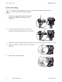
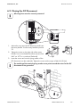
4.1 Opening the Sunny Boy
1. Remove the six screws and conical spring washers from the enclosure cover. Pull the cover
forward smoothly.
2. Put the cover, screws, and conical spring washers to one side so that they do not get in the way.
NOTICE
Ingress of moisture when mounting and installing the Sunny Boy
Potential damage to the Sunny Boy.
• For conduit hubs, use UL listed raintight, wet location hubs for entry into the enclosure.
• Do not open the Sunny Boy in the event of rain or a high level of humidity (> 95 %).
Damage to the seal of the enclosure lid during frost
When opening the Sunny Boy during frost, the seal of the enclosure lid can be damaged.
There may be an ingress of moisture damaging the Sunny Boy.
• Do not open the Sunny Boy when the outdoor temperature is below 23 °F ( − 5 °C).
Electrostatic discharges through touching component parts
Potential damage to the Sunny Boy.
• Ground yourself before touching any electronic component.
SB50US-80US-IA-en-37
SB50US-80US-IA-en-37
19
AC Voltage Configuration
SMA America, LLC
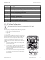
4.2 Locating Internal Component Parts
B
A
C D
R
A B + -
V
E
277 V
208
0V
240
V
2 3 5 7
Q
H
O
N
M
COMBINED
P
1
2
3
4
UNGROUNDED
GROUNDING
ELECTRODE
CONDUCTOR
L1
GROUNDED
L2
N
G
F
I
K
L
Position
A
B
C
D
E
F
20
Description
Sockets for optional communication Piggy-Back (RS485 or wireless)
Display
Status LEDs
Jumpers for configuring the AC voltage and the fan test
Terminal blocks for configuring the AC voltage
Ground terminal (PE)
SB50US-80US-IA-en-37
Installation Manual
SMA America, LLC
Position
G
H
I
K
L
M
N
O
P
Q
R
AC Voltage Configuration
Description
Output AC conductor terminals (N, L1, and L2)
Connecting terminal plate, PV grounding conductor, + DC grounding conductor
DC varistor terminal with DC varistors*
Output AC conductor terminals (L1, L2, N and PE)
Terminal PV GROUNDED (PV array input)
Terminal PV UNGROUNDED (PV array input)
Combined terminal UNGROUNDED
Terminal DC − (PV array input)
Terminal DC+ (PV array input)
Flat male tab for grounding the cable shield for communication
Terminal for optional communication (RS485)
* only SB 5000US-12/SB 6000US-12/SB 7000US-12/SB 8000US-12
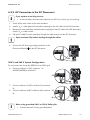
4.3 AC Voltage Configuration
The Sunny Boy 8000-US must not be connected to a 208 V grid.
The Sunny Boy is compatible with the following grid types:
• 208 V AC (not Sunny Boy 8000-US)
• 240 V AC
• 277 V AC
The Sunny Boy is configured ex works for connection to
the power distribution grid with a voltage of 240 V AC.
The Sunny Boy can be configured for other voltages.
4 cables are inserted into the enclosure via a cable
support sleeve. Each cable is labeled with its respective
voltage.
1. Connect the cable with the correct voltage to the
left terminal block (A).
2. To adjust the AC voltage, select the cable with the
correct voltage at the right terminal block (C).
Connect the selected cable to the left side of the left
terminal block (A).
3. Secure all screw terminals. If spring-type terminals
are available, close the levers of the terminals by
pressing down.
SB50US-80US-IA-en-37
SB50US-80US-IA-en-37
21
AC Voltage Configuration
SMA America, LLC
Tightening torque of the screw terminals for the left terminal block:
Gray terminal blocks (Weidmüller)
Green terminal blocks (Phoenix)
18 in-lb. (2 Nm)
22 in-lb. (2.5 Nm)
Do not remove the cable in the left terminal block with the marking 0 V (B).
This always remains connected to the right side of the left terminal block.
4. Connect and fasten all cables not being used to the right terminal block (C). Tightening torques
of the screw terminals for the right terminal block (cables not being used):
Gray terminal blocks (Weidmüller)
Green terminal blocks (Phoenix)
11 in-lb. (1.2 Nm)
15 in-lb. (1.7 Nm)
If the Sunny Boy is configured for the wrong
input voltage, this error message appears in
the display:
Disturbance
XFMR
• Check if the configuration of the AC voltage is correct.
Automatic Grid Voltage Detection
The Sunny Boy automatically detects the grid voltage that it must feed in. Depending on the voltage
and the phase angle between L1‑N and L2‑N, the inverter determines whether it is connected to a
208 V, 240 V, or 277 V grid. If the Sunny Boy is configured for the wrong grid voltage (for example,
the inverter was configured for 240 V and then connected to a 208 V grid), the Sunny Boy displays
an error message.
The table below contains the limiting values for voltage and frequency in the AC terminal:
Voltage range for 208 V nominal value, phase-phase (not Sunny
Boy 8000-US)
Voltage range for 240 V nominal value, phase-phase
Voltage range for 277 V nominal value, phase-neutral conductor
Frequency range
183 V … 229 V
211 V … 264 V
244 V … 305 V
59.3 Hz … 60.5 Hz
If the power distribution grid uses a neutral conductor, the responsible authority can demand that a
neutral conductor be connected to the inverter.
To set the configuration jumpers, observe the procedure in 4.4 ”Jumper for System Configuration”
(page 24).
To connect a neutral conductor to the Sunny Boy, observe section 6.5.2 ”AC Connection in the DC
Disconnect” (page 43) or section "AC Connection in the DC Disconnect" on page 43.
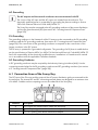
Configuration of Grid Voltage
The figure on the next page illustrates common grid forms. Note that it is not the phase relationship
that is important when connecting the Sunny Boy to the power distribution grid, but the voltage
compatibility.
22
SB50US-80US-IA-en-37
Installation Manual
SMA America, LLC
AC Voltage Configuration
*
*
*
*The Sunny Boy 8000-US must not be connected to a 208 V grid.
When using grounded 240 V or 208 V Delta grids:
• Connect terminal L2 to the grounded phase.
SB50US-80US-IA-en-37
SB50US-80US-IA-en-37
23
AC Voltage Configuration
SMA America, LLC
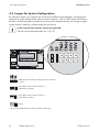
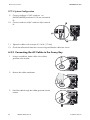
4.4 Jumper for System Configuration
By setting the jumper, you configure the Sunny Boy for different grid topologies. This means that
operation in system configurations without neutral conductors, such as 208 V and 240 V Delta, is
possible. The following figure provides an overview of the standard settings, the settings for grids
without neutral conductors, and the settings for the fan test.
In the event of frost, the fan cannot be inspected
The fans are not activated under 32 °F (0 °C).
208V with neutral conductor*240 V with neutral conductor
or 277 V
208 V Delta, without neutral conductor or *
208 V Delta, grounded *
240 V Delta, without neutral conductor or
240 V Delta, grounded
Fan test
* The Sunny Boy 8000-US must not be connected to a 208 V grid.
24
SB50US-80US-IA-en-37
Installation Manual
SMA America, LLC
AC Voltage Configuration
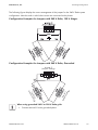
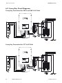
The following figures display the correct arrangement of the jumpers for the 240 V Delta system
configuration: Note the order in which the inverters are connected to the phases.
Configuration Examples for Jumpers with 240 V Delta, 120 V Stinger
Configuration Examples for Jumpers with 240 V Delta, Grounded
Inverter 3
Jumpers Settings
L2
L1
L1
Jum Inve
per rter
sS 1
etti
ngs
L2
r 2 gs
erte ttin
Invers Se
p
Jum
When using grounded 240 V or 208 V Delta grids
• Connect terminal L2 to the grounded phase.
SB50US-80US-IA-en-37
SB50US-80US-IA-en-37
25
Assembly
SMA America, LLC
5 Assembly
5.1 Safety
DANGER
Danger to life due to fire or explosions.
With electrical devices, there is always a certain danger that a fire may break out.
• Do not install the inverter in the vicinity of combustible materials.
• Do not install the inverter in potentially explosive areas.
CAUTION
The Sunny Boy may fall down due to inappropriate mounting
Contusions or bone fractures due to the heavy weight of the Sunny Boy.
• When mounting the Sunny Boy, take its weight of 148 lb. (67 kg) into consideration.
• Use appropriate mounting material for the mounting location of the inverter:
– For mounting on plasterboard, do not use hollow wall anchors or toggle bolts.
– Wooden supporting posts must be present behind the installation points on
plasterboard.
• Use suitable lifting technique when mounting.
The inverter can become hot during operation
Burn injuries may be possible when touching the enclosure.
• Install the inverter in such a way that it cannot be touched accidentally.
26
SB50US-80US-IA-en-37
Installation Manual
SMA America, LLC
Assembly
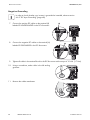
5.2 Requirements for the Mounting Location
Observe the following conditions during installation:
• The installation method and mounting location must be suitable for the weight and dimensions
of the Sunny Boy (see section 11 ”Technical Data” (page 91)).
• Note the dimensions of the DC disconnect (Page 34).
• Mount the inverter on a stable surface.
• The mounting location must be accessible at all times.
max. 45°
• Mount vertically or tilted backward at max. 45°.
• The connection area must point downward.
• Do not install the inverter tilting forward.
• Do not install the inverter horizontally.
• Install the inverter at eye level in order to be able to read out the operating state at any time.
• The ambient temperature must be below +113 °F (+45 °C).
• Do not expose the inverter to direct sunlight.
• In the living area, do not install inverters on a
plasterboard wall or similar wall.
The Sunny Boy may emit noises when in use which
can be regarded as a nuisance.
SB50US-80US-IA-en-37
SB50US-80US-IA-en-37
27
Assembly
SMA America, LLC
• Observe recommended clearances to the walls as well as to other inverters or objects. Thus, you
will prevent the inverter's power output from being reduced due to excessive temperatures.
The National Electrical Code® may stipulate greater clearances (see National Electrical
Code®, Section 110.26). Installations in Canada must be carried out in accordance with
the applicable Canadian standards.
• If several inverters are mounted in areas with high ambient temperatures, increase the
clearances and ensure a sufficient fresh-air supply. Thus, you will prevent the inverter power
from being reduced due to too high temperatures.
Position
Top
Bottom
Left
Right
Front
Clearance
12 in. (300 mm)
36 in. (900 mm)
12 in. (300 mm)
12 in. (300 mm)
2 in. (50 mm)
12 in.
Recommended clearances
12 in
.
.
12 in.
2
12 in
in.
If the Sunny Boy is installed outdoors
• Observe minimum clearance to the ground of 36 in. (900 mm).
28
SB50US-80US-IA-en-37
Installation Manual
SMA America, LLC
Assembly
Dimensions of the Sunny Boy
5.3 Mounting with Wall Mounting Bracket
The Sunny Boy is supplied with a T-shaped wall mounting bracket that is suitable for most walls. The
wall must be vertical and stable enough to carry a weight of 145 lb. (67 kg) for a long period of time.
For the wall material, use suitable fastening elements no smaller than ¼ in.
SB50US-80US-IA-en-37
SB50US-80US-IA-en-37
29
Assembly
SMA America, LLC
Dimensions of the Wall Mounting Bracket
2 in.
50 mm
2 in.
50 mm
2 in.
50 mm
2 in.
50 mm
2 in.
50 mm
2 in.
50 mm
2 in.
50 mm
11 in. (280 mm)
(80 mm)
23 in. (584 mm)
3 in. (74 mm)
2 in.
50 mm
30
SB50US-80US-IA-en-37
Installation Manual
SMA America, LLC
Assembly
5.3.1 Possibilities for Mounting the Wall Mounting Bracket
Mounting on a Stone Wall
Secure the wall mounting bracket with at least 3 screws.
The position of the screws on the wall mounting bracket is
as follows:
• 1 screw on the upper left side.
• 1 screw on the upper right side.
• 1 screw below.
Mount the wall mounting bracket as described in section
5.3.2 ”Mounting the Wall Mounting Bracket”
(page 32).
Mounting on a Wooden Wall with a Stud or on a Pillar
Secure the wall mounting bracket with at least 3 screws.
The position of the screws on the wall mounting bracket is
as follows:
• 2 screws at the upper middle.
• 1 screw below.
Mount the wall mounting bracket as described in section
5.3.2 ”Mounting the Wall Mounting Bracket”
(page 32).
Mounting on a Wooden Wall with Two Studs
Secure the wall mounting bracket with at least 4 screws.
The position of the screws on the wall mounting bracket is
as follows:
• 2 screws on the upper left side.
• 2 screws on the upper right side.
Use the four outer mounting holes on the left and right
sides of the wall mounting bracket.
Mount the wall mounting bracket as described in section
5.3.2 ”Mounting the Wall Mounting Bracket”
(page 32).
SB50US-80US-IA-en-37
SB50US-80US-IA-en-37
31
Assembly
SMA America, LLC
5.3.2 Mounting the Wall Mounting Bracket
1. Position the wall mounting bracket at the installation location. If possible, select eye level.
2. Align the wall mounting bracket with a spirit level. The bottom end of the wall mounting bracket
reaches approximately to the bottom corner of the inverter.
WARNING
Electric shock due to damaged electric cables
Electric cables may be located behind the installation points which can be damaged when
mounting the inverter.
• Ensure that no electric cables are located behind the installation points.
3. Use the wall mounting bracket as a template. Mark at least 3 holes in the horizontal or vertical
position of the wall mounting bracket (see section 5.3.1 ”Possibilities for Mounting the Wall
Mounting Bracket” (page 31)).
4. Remove the mounting bracket and drill the holes at the markings.
Information for the installation
The diameter of the bore holes must correspond to the fastening elements that you use for
mounting the inverter.
Mounting on a concrete wall:
• The hole diameter must be the same as the outer diameter of the screw anchors.
• Insert suitable screw anchors into the bore holes.
Mounting on a wall with wooden studs:
• The hole diameter must correspond to the screw diameter used. The screws should
be stainless steel. The diameter of the screws must correspond to the diameter of the
holes in the wall mounting bracket. The screws must be long enough to reach a depth
in the wall of 11⁄2 in.
5. Insert the screws into the bore holes through the holes in the wall mounting bracket.
6. Tighten the screws clockwise until the wall mounting bracket hangs securely on the wall.
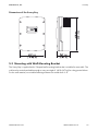
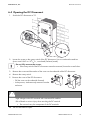
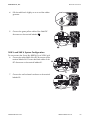
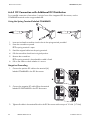
5.4 Mounting the DC Disconnect
Inserting the DC varistors
The supplied DC varistors must only be used for the following inverter types:
SB 5000TLUS-12/SB 6000US-12/SB 7000US-12/SB 8000US-12.
32
SB50US-80US-IA-en-37
Installation Manual
SMA America, LLC
Assembly
Position
Description
A
Terminals for DC varistors
1. Open the DC disconnect as described in Section 6.4 ”Opening the DC Disconnect” (page 41).
2. Equip the 3 terminals (A) with DC varistors:
– Insert the insertion tool into the rectangular
opening of the terminal.
– Insert the DC varistor into the terminal.
– Pull the insertion tool out of the rectangular
opening of the terminal.
3. Ensure that all DC varistors in the terminals are
securely in place.
4. Close the DC disconnect as described in Section 6.9 ”Closing the DC Disconnect” (page 57).
SB50US-80US-IA-en-37
SB50US-80US-IA-en-37
33
Assembly
SMA America, LLC
5.4.1 Mounting the DC disconnect
Dimensions of the DC Disconnect
Attach the DC disconnect to the two lower holes of the wall mounting bracket using the two screws
and washers provided.
1. Insert the screws with the washers through the holes
of the anchorage brackets of the DC disconnect.
The teeth of the washers must lie on the anchorage
brackets of the DC disconnect.
2. Put the DC disconnect onto the wall mounting
bracket.
3. Tighten the screws with a tightening torque of
44 in‑lb. (5 Nm).
34
SB50US-80US-IA-en-37
Installation Manual
SMA America, LLC
Assembly
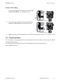
5.4.2 Mounting the Sunny Boy on a Wall Mounting Bracket
CAUTION
The Sunny Boy may fall down due to inappropriate mounting
Contusions or bone fractures due to the heavy weight of the Sunny Boy.
• Transport the Sunny Boy between two persons, using the side handles above and
below.
or
• Put a steel bar with a maximum diameter of 11⁄8 in. (30 mm) through the enclosure
opening above and transport it between two people.
1. Remove the handle covers on the right and left side of the Sunny Boy.
2. Hook the Sunny Boy with the enclosure opening
onto the rear panel in the wall mounting bracket. The
Sunny Boy must be seated on the middle of the wall
mounting bracket.
3. Screw the Sunny Boy onto the wall mounting bracket
on both sides with the screws supplied.
4. Tighten the screws clockwise with a tightening torque
of 44 in-lb. (5 Nm).
5. Place handle covers on the handles.
To help you identify the sides, the ventilation grids
are marked "rechts/right" and "links/left" on the
inside.
The ventilation grids prevent dirt and insects from
entering the inverter and can be reordered from
SMA if required. See section 12 ”Spare Parts and
Accessories” (page 101).
SB50US-80US-IA-en-37
SB50US-80US-IA-en-37
35
Electrical Connection
SMA America, LLC
6 Electrical Connection
DANGER
High voltages on the AC and DC cables
Risk of death or serious injury due to electric shock.
• Only connect the inverters as described in this manual.
• Only electrically qualified persons may work on the inverter.
NOTICE
Ingress of moisture when mounting and installing the Sunny Boy
Potential damage to the Sunny Boy.
• For conduit hubs, use UL listed raintight, wet location hubs for entry into the enclosure.
• Do not open the Sunny Boy in the event of rain or a high level of humidity (> 95 %).
Damage to the seal of the enclosure lid during frost
When opening the Sunny Boy during frost, the seal of the enclosure lid can be damaged.
There may be an ingress of moisture damaging the Sunny Boy.
• Do not open the Sunny Boy when the outdoor temperature is below 23 °F ( − 5 °C).
Electrostatic discharges through touching component parts
Potential damage to the Sunny Boy.
• Ground yourself before touching any electronic component.
Ground faults, unreliable and highly resistive connections due to Wire Nuts®
Potential damage to or failure of the Sunny Boy.
• Do not use Wire Nuts®.
Electrical Installations
All electrical installations must be carried out according to the applicable electrical
standards on site and the National Electrical Code ANSI/NFPA 70. Installations in
Canada must be carried out according to the applicable Canadian standards.
Before connecting the Sunny Boy to the power distribution grid, contact your local electric
utility company. This connection must be made only by qualified personnel.
36
SB50US-80US-IA-en-37
Installation Manual
SMA America, LLC
Electrical Connection
AC Grounding
The AC outputs and the neutral conductors are not connected with PE
The circuits of the AC input and the AC output are isolated from the enclosure. The
electrically qualified person is responsible for grounding the plant according to Section
250 of the National Electrical Code ANSI/NFPA 70.
The Sunny Boy must be connected to the AC grounding conductor of the power distribution
grid via the ground terminal (PE) (see section 4.2 ”Locating Internal Component Parts”
(page 20)).
PV Grounding
The grounding conductor in the framework of the PV array must be connected to the PV grounding
conductor and the DC grounding conductor (see section 4.2 ”Locating Internal Component Parts”
(page 20)). The cross-section of the grounding conductor corresponds to the cross-section of the
largest conductor in the DC system.
The PV array is operated in a grounded configuration. The grounding of a PV plant is established as
per the specifications of Section 690.41 to 690.47 of the National Electrical Code ANSI/NFPA 70
and is the responsibility of the electrically qualified person. Installations in Canada must be carried
out in accordance with the applicable Canadian standards.
DC Grounding Conductor
A DC grounding conductor may be required by the Authority Having Jurisdiction (AHJ). Use the
connecting terminal plate for the PV grounding conductor and DC grounding conductor (see section
4.2 ”Locating Internal Component Parts” (page 20)).
6.1 Connection Area of the Sunny Boy
The DC input of the PV array and the output of the AC power distribution grid are connected inside
the enclosure. The internal AC and DC connecting terminal plates are designed for a maximum size
of 6 AWG. Suitable enclosure openings are on the underside of the Sunny Boy.
Position
A
B
C
Description
in. screws for communication cable with filler-plugs
in. DC opening with double membrane adapter
in. AC opening with double membrane adapter
1⁄
2
3⁄
4
3⁄
4
SB50US-80US-IA-en-37
SB50US-80US-IA-en-37
37
Electrical Connection
SMA America, LLC
6.2 Sunny Boy Circuit Diagrams
Sunny Boy Connections for 208 V and 240 V AC Grids
SMA SOLAR TECHNOLOGY
Betrieb
Operation
Erdschluss
Earth Fault
SUNNY BOY
Störung
Failure
PV-Ungrounded
N L1 L2
PV-Grounded
2p 50 Amp
SMA DC-Disconnect
Sunny Boy Connections for 277 V AC Grids
SMA SOLAR TECHNOLOGY
Betrieb
Operation
Erdschluss
Earth Fault
SUNNY BOY
Störung
Failure
PV-Ungrounded
PV-Grounded
N
1p 40 Amp
SMA DC-Disconnect
38
SB50US-80US-IA-en-37
Installation Manual
SMA America, LLC
Electrical Connection
6.2.1 Wiring with DC disconnect
Procedure and Order
1. Switch off all energy sources. Open all AC and DC disconnect switches and breakers.
2. Wiring from AC breaker to DC disconnect.
3. AC wiring from DC disconnect to Sunny Boy.
4. Wiring from PV array to DC disconnect.
5. DC wiring from DC disconnect to Sunny Boy.
6. Switch DC disconnect to position "1".
7. Switch on AC breaker.
Removing Sunny Boy from Wiring
• Disconnect all AC disconnect switches.
• Switch DC disconnect to position "0".
• Always disconnect the AC side before the DC side.
• When the Sunny Boy is switched off, remove the wiring in reverse order.
SB50US-80US-IA-en-37
SB50US-80US-IA-en-37
39
Electrical Connection
SMA America, LLC
6.3 Opening the Sunny Boy
DANGER
High voltages are present in the Sunny Boy during operation.
Death or serious injury due to electric shock.
• Only open the Sunny Boy in the order described as follows.
1. Switch off all AC and DC breakers or switch-disconnectors. Ensure they cannot reconnect
accidentally.
2. Wait at least 5 minutes until the residual voltage has been drained.
3. Remove the 6 screws and conical spring washers from the enclosure lid. Pull the lid smoothly off
forwards.
NOTICE
Moisture can penetrate the open Sunny Boy
Potential damage to the Sunny Boy.
• Do not open the Sunny Boy in the event of rain or a high level of humidity (> 95 %).
• Handle the enclosure lid with care.
Damage to the seal of the enclosure lid during frost
When opening the Sunny Boy during frost, the seal of the enclosure lid can be damaged.
There may be an ingress of moisture damaging the Sunny Boy.
• Do not open the Sunny Boy when the outdoor temperature is below 23 °F ( − 5 °C).
Electrostatic discharges through touching component parts
Potential damage to the Sunny Boy.
• Ground yourself prior to touching a component part.
☑ The Sunny Boy is open.
40
SB50US-80US-IA-en-37
Installation Manual
SMA America, LLC
Electrical Connection
6.4 Opening the DC Disconnect
1. Switch the DC disconnect to "0".
2. Loosen the screw on the rotary switch of the DC disconnect. Use a cross-head screwdriver
(screw used: UNC no. 5x3/4 in., cross-head, flat-head, metal).
Do not fully remove the screws.
• If the rotary switch of the DC disconnect cannot be removed, loosen the screw further.
3. Remove the screw and the washer of the cover on the underside of the DC disconnect.
4. Remove the rotary switch.
5. Remove the cover of the DC disconnect:
– Pull the cover on the underside forward.
5
4
– In the process, simultaneously remove it from the
enclosure.
DANGER
High voltages at the DC terminals with connected PV modules
Risk of death or serious injury when touching the DC terminal.
• Do not touch any live component of the DC terminals.
☑ The DC disconnect is open.
SB50US-80US-IA-en-37
SB50US-80US-IA-en-37
41
Electrical Connection
SMA America, LLC
6.5 AC Connection
CAUTION
Rist of fire
Overcurrent may lead to a cable fire.
• The electrical installation must include overvoltage protection for the AC output
circuit.
• Set up the overvoltage protection for a maximum of 50 A.
Carry out all electrical installations according to all of the applicable on-site electrical
standards and the National Electrical Code® (NE, ANSI/NFPA 70).
See National Electrical Code, Section 690-64(b) (2).
For installations in Canada, observe the applicable Canadian standards.
6.5.1 AC Connection Requirements
For all AC cable connections to the Sunny Boy, use a max. 6 AWG copper wire that is designed for
+194 °F (+90 °C) – even if voltage drop and other considerations mean that the use of larger cable
cross-sections is required.
Only use solid wire or stranded wire
• Do not use fine-wire strands.
• Use the free of charge "Sunny Design" at www.SMA-America.com to design your PV
plant.
Ambient temperature
The higher the ambient temperature, the higher the power losses.
• Use cables with large cable cross-sections in installation sites with high ambient
temperatures.
Routing method
The cables heat up during operation. If there are several cables in a conduit, the
temperature of all cables increases.
• Use cables with a large cross-section if you lay several cables in one conduit.
42
SB50US-80US-IA-en-37
Installation Manual
SMA America, LLC
Electrical Connection
6.5.2 AC Connection in the DC Disconnect
If you replace an existing inverter
• In the switchbox, disconnect the cables for the AC line on which you are working.
1. Switch off the main switch in the main switchbox.
2. Install a 3⁄4 in. cable gland in the breakout opening for the AC cables of the DC disconnect.
3. Between the main switchbox and the breakout opening for the AC cables of the DC disconnect,
install a 3⁄4 in. cable conduit.
4. Pull the AC cables from the switchbox through the cable conduit into the DC disconnect.
Open terminals fully before feeding through the cables
5. Connect the AC device grounding conductor to the
PE terminal labeled
in the DC disconnect.
V
V
A B + -
208
240
L2
N
PE
COMBINED
L1
277 V
2 3 5 7
GROUNDED
1
2
3
4
UNGROUNDED
GROUNDING
ELECTRODE
CONDUCTOR
GROUNDED
L1
L2
N
208 V and 240 V System Configuration
Do not connect the Sunny Boy 8000-US to a 208 V grid.
6. Connect conductor L1 (AC conductor 1 or
UNGROUNDED) to terminal L1.
7. Connect conductor L2 (AC conductor 2) to terminal
L2.
V
L2
V
A B + -
240
L1
277 V
2 3 5 7
GROUNDED
208
8. Connect conductor N (AC conductor N) to terminal L2
N.
N
COMBINED
N
1
2
3
4
UNGROUNDED
GROUNDING
ELECTRODE
CONDUCTOR
GROUNDED
L1
L2
N
When using grounded 240 V or 208 V Delta grids
• Connect terminal L2 to the grounded phase.
SB50US-80US-IA-en-37
SB50US-80US-IA-en-37
43
Electrical Connection
SMA America, LLC
277 V System Configuration
9. Connect conductor L1 (AC conductor 1 or
UNGROUNDED) to terminal L1. Do not use terminal
L2.
10. Connect conductor N (AC conductor N) to terminal
N.
11. Tighten the cables with a torque of 15 in-lb. (1.7 Nm).
12. Check that all terminals have the correct wiring and that the cables are secure.
6.5.3 Connecting the AC Cables in the Sunny Boy
1. Using a screwdriver, make a hole in the rubber
grommet in the inverter.
208
240
V
V
A B + -
277 V
2 3 5 7
2. Remove the rubber membrane.
208
240
V
V
A B + -
277 V
2 3 5 7
3. Feed the cable through the rubber grommet into the
inverter.
V
SB50US-80US-IA-en-37
V
240
44
277 V
A B + -
208
2 3 5 7
Installation Manual
SMA America, LLC
Electrical Connection
4. Pull the cable back slightly so as to seal the rubber
grommet.
208
240
V
V
A B + -
277 V
2 3 5 7
5. Connect the green-yellow cable of the SMA DC
disconnect to the terminal labeled
.
208 V and 240 V System Configuration
A B + -
COMBINED
1
2
3
4
UNGROUNDED
208
240
V
V
2 3 5 7
277 V
Do not connect the Sunny Boy 8000-US to a 208 V grid.
6. Connect the white cable of the DC disconnect to the
terminal labeled N. Connect the black cable of the
N
DC disconnect to the terminal labeled L1.
GROUNDING
ELECTRODE
CONDUCTOR
L1
GROUNDED
L2
N
L1
7. Connect the red insulated conductor to the terminal
labeled L2.
V
208
240
277 V
A B + -
V
2 3 5 7
COMBINED
X
X
X
L2
SB50US-80US-IA-en-37
1
2
3
4
UNGROUNDED
SB50US-80US-IA-en-37
GROUNDING
ELECTRODE
CONDUCTOR
GROUNDED
L1
L2
N
45
Electrical Connection
SMA America, LLC
277 V System Configuration
1
2
3
4
UNGROUNDED
V
0V
240
COMBINED
9. Connect the red insulated conductor to the terminal
labeled
.
0V
240
V
V
A B + -
277 V
2 3 5 7
208
8. Connect the white cable of the DC disconnect to the
terminal labeled N. Connect the black insulated
conductor of the DC disconnect to the terminal
labeled L1.
GROUNDING
ELECTRODE
CONDUCTOR
GROUNDED
L1
L2
N
black
10. Tighten the AC terminal blocks in the inverter with the following torques:
Gray terminal blocks (Weidmüller)
Green terminal blocks (Phoenix)
10 … 6 AWG: 18 in-lb. (2 Nm)
8 … 6 AWG: 40 in-lb. (4.5 Nm)
10 AWG: 22 in-lb. (2.5 Nm)
11. Check that all terminals have the correct wiring and that the cables are secure.
6.6 DC Connection
DANGER
High voltages on PV modules that are exposed to light
Risk of death due to electric shock from touching a DC conductor.
• Do not touch the DC conductor.
High voltages in the DC cables
Risk of death or serious injury from touching a DC cable.
• Only connect the DC cable from the PV module to the inverter as described in this
manual.
NOTICE
Potential damage to the inverter due to overvoltage.
• The DC input voltage of the PV modules must not exceed the maximum values of the
inverter. Observe the information on the type label.
• Check the polarity and the open-circuit voltage of the PV strings before connecting
the DC cables to the inverter.
• Configure the DC input voltage range accordingly before connecting the PV modules
to the inverter. Use "Sunny Design" on www.SMA-America.com for string
configuration.
46
SB50US-80US-IA-en-37
Installation Manual
SMA America, LLC
Electrical Connection
Simplified Circuit Diagram of a PV Plant
6.6.1 DC Connection Requirements
Cable Dimensioning
All electrical installations must be carried out according to all of the applicable on-site electrical
standards and the National Electrical Code® ANSI/NFPA 70 or the Canadian Electrical Code®
CSA C22.1 and the applicable standards in Canada.
When selecting the cable type and the line cross-section, observe the following requirements
depending on the type of installation:
• For all DC copper wire cable connections, use size 10 ... 6 AWG (6 ... 16 mm²), which is
designed for +194 °F (+90 °C).
• Use only solid wire or rough wire strands. Do not use fine-wire strands.
• Route the PV lines precisely in the entire PV plant and do not coil.
Correct String Configuration
• Use "Sunny Design" on www.SMA-America.com for string configuration.
SB50US-80US-IA-en-37
SB50US-80US-IA-en-37
47
Electrical Connection
SMA America, LLC
Fuses
The DC disconnect for the inverter must have a minimum rating of 600 V DC and 36 A continuous.
The DC disconnect is supplied with 4 fuses (one fuse per string) designed for 15 A and 600 V DC.
The 4 fuses of the DC disconnect may be used for a maximum of 20 A and 600 V DC.
When dimensioning the fuses, observe the National Electrical Code® 690.8 and 690.9.
6.6.2 DC Input Grounding
The Sunny Boy is configured ex works for plants with negative PV array grounding. Certain types of
PV modules may make it necessary to ground the negative pole rather than the positive pole.
Position of the GFDI Fuse and the Jumper for Negative Grounding
2
1
1. Insert the fuse in position (1).
2. Insert the jumper in position (2).
Position of the GFDI Fuse and the Jumper for Positive Grounding
2
1
1. Insert the fuse in position (1).
2. Insert the jumper in position (2).
48
SB50US-80US-IA-en-37
Installation Manual
SMA America, LLC
Electrical Connection
6.6.3 Connecting the DC Cables in the DC disconnect
Fully open the terminal before feeding through the cables
1. Open the AC breaker and secure against turning on again.
2. Install a 3⁄4 in. cable gland in the breakout opening for the DC cables of the DC disconnect. The
breakout opening is on the left side of the DC disconnect. Secure the cable gland to the inner
side of the SMA DC disconnect with the matching locknut.
3. Install a 3⁄4 in. cable conduit between the enclosure of the DC disconnect and the PV array.
4. Pull the DC cables, the grounding cables of the PV array, and the grounding conductor through
the cable conduit and inside the SMA DC disconnect.
The DC disconnect has provisions for up to 4 PV strings. The terminal blocks
PV UNGROUNDED and PV GROUNDED each have 4 termination points. This means that
4 pairs of DC input cables can be connected in parallel.
5. Connect the grounding cable of the PV array to the
terminal (A) for the grounding conductor.
6. Connect the grounding conductor to the terminal (B)
for the grounding conductor.
SB50US-80US-IA-en-37
SB50US-80US-IA-en-37
49
Electrical Connection
SMA America, LLC
Negative Grounding
In order to check whether your inverter is grounded as intended, observe section
6.6.2 ”DC Input Grounding” (page 48).
7. Connect the positive DC cables to the terminal (A)
labeled PV UNGROUNDED in the DC disconnect.
8. Connect the negative DC cables to the terminal (A)
labeled PV GROUNDED in the DC disconnect.
9. Tighten all cables in the terminal blocks in the DC disconnect with a torque of 15 in‑lb. (1.7 Nm).
10. Using a screwdriver, make a hole in the left sealing
grommet.
208
240
V
V
A B + -
277 V
2 3 5 7
11. Remove the rubber membrane.
V
SB50US-80US-IA-en-37
V
240
50
277 V
A B + -
208
2 3 5 7
Installation Manual
SMA America, LLC
Electrical Connection
12. Pull the DC cables from the SMA DC disconnect
inside the Sunny Boy.
208
240
V
V
A B + -
277 V
2 3 5 7
13. Pull the cable back slightly so as to seal the sealing
grommet.
V
V
240
277 V
A B + -
208
2 3 5 7
14. Connect the black cable (PV UNGROUNDED) to
the terminal labeled DC+ in the Sunny Boy.
15. Connect the white cable (PV GROUNDED) to the
terminal labeled DC − in the Sunny Boy.
16. Tighten all cables in the AC and DC terminal blocks in the Sunny Boy:
Gray terminal blocks (Weidmüller)
Green terminal blocks (Phoenix)
10 … 6 AWG: 18 in-lb. (2 Nm)
8 … 6 AWG: 40 in-lb. (4.5 Nm)
10 AWG: 22 in-lb. (2.5 Nm)
17. Check whether all connections are correctly wired. Carry out a tensile test to see whether all
cables are tight.
SB50US-80US-IA-en-37
SB50US-80US-IA-en-37
51
Electrical Connection
SMA America, LLC
Positive Grounding
In order to check whether your inverter is grounded as intended, observe section
6.6.2 ”DC Input Grounding” (page 48).
1. Connect the negative DC cable to the terminal
labeled PV UNGROUNDED (A) in the DC
disconnect.
2. Connect the positive DC cable to the terminal
labeled PV GROUNDED (A) in the DC disconnect.
3. Tighten all cables in the terminal blocks in the DC disconnect with a torque of 15 in-lb. (1.7 Nm).
4. Using a screwdriver, make a hole in the left sealing
grommet.
208
240
V
V
A B + -
277 V
2 3 5 7
5. Remove the rubber membrane.
V
SB50US-80US-IA-en-37
V
240
52
277 V
A B + -
208
2 3 5 7
Installation Manual
SMA America, LLC
Electrical Connection
6. Pull the DC cables from the SMA DC disconnect
inside the Sunny Boy.
208
240
V
V
A B + -
277 V
2 3 5 7
7. Pull the cable back slightly so as to seal the sealing
grommet.
V
V
240
277 V
A B + -
208
2 3 5 7
8. Connect the white cable (PV GROUNDED) to the
terminal labeled DC+ in the Sunny Boy.
9. Connect the black cable (PV UNGROUNDED) to
the terminal labeled DC − in the Sunny Boy.
10. Tighten all cables in the AC and DC terminal blocks in the SMA DC disconnect:
Gray terminal blocks (Weidmüller)
Green terminal blocks (Phoenix)
10 … 6 AWG: 18 in-lb. (2 Nm)
8 … 6 AWG: 40 in-lb. (4.5 Nm)
10 AWG: 22 in-lb. (2.5 Nm)
11. Check whether all connections are correctly wired. Carry out a tensile test to see whether all
cables are tight.
SB50US-80US-IA-en-37
SB50US-80US-IA-en-37
53
Electrical Connection
SMA America, LLC
6.6.4 DC Connection with Additional DC Distribution
For a parallel connection of more than 1 string in front of the integrated DC disconnect, use the
COMBINED terminal on the non-grounded side.
Using the Spring Terminal labeled COMBINED
1. Insert an insulated screwdriver into the slot in the spring terminal provided.
2. Press the screwdriver upward.
☑ The spring terminal is open.
3. Feed the stripped cable into the spring terminal.
4. Pull the screwdriver back into its original position.
5. Remove the screwdriver.
☑ The spring terminal is closed and the cable is fixed.
6. Pull on the cable to check whether it is secure.
Negative Grounding
1. Connect the positive DC cable to the terminal (A)
labeled COMBINED in the DC disconnect.
2. Connect the negative DC cable (B) to the terminal
labeled PV GROUNDED in the DC disconnect.
3. Tighten all cables in the terminal blocks in the DC disconnect with a torque of 15 in‑lb. (1.7 Nm).
54
SB50US-80US-IA-en-37
Installation Manual
SMA America, LLC
Electrical Connection
Positive Grounding
1. Connect the negative DC cable to the terminal (A)
labeled COMBINED in the DC disconnect.
2. Connect the positive DC cable to the terminal (B)
labeled PV GROUNDED in the DC disconnect.
3. Tighten all cables in the terminal blocks in the DC disconnect with a torque of 15 in‑lb. (1.7 Nm).
6.7 Communication
The Sunny Boy can be equipped with a communication interface in order to communicate with SMA
communication products.
You will find further information and a list of applicable communication products at
www.SMA‑America.com.
SB50US-80US-IA-en-37
SB50US-80US-IA-en-37
55
Electrical Connection
SMA America, LLC
6.8 Closing the Sunny Boy
NOTICE
Damage to the enclosure lid may affect the seal between the enclosure lid and the
enclosure.
There may be an ingress of moisture.
Potential damage to the Sunny Boy.
• Handle the enclosure lid with care.
• Check the seal on the inner side of the enclosure lid for damage.
• When closing, no moisture may remain in the enclosure.
1. Mount the enclosure lid onto the Sunny Boy. The 6
holes in the cover must be aligned with the 6 thread
bores of the enclosure.
Check the line routing
Cables must not obstruct the seal of the
enclosure lid. The enclosure lid must not exert
any pressure on the connections.
2. Hold the enclosure lid. Tighten the 6 screws with the
conical spring washers through the holes in the
enclosure lid into the threaded bores of the
enclosure.
The toothing of the conical spring washers
must point toward the enclosure lid
Do not damage the thread of the screws.
Do not use power tools to tighten the screws.
3. Check whether the enclosure lid is laying evenly on
the enclosure.
4. Tighten the 6 screws with 53 in-lb. (6 Nm).
All fastening elements are required for the grounding and weatherproof sealing
of the Sunny Boy
• To fasten the enclosure lid, use all 6 screws with conical spring washers.
56
SB50US-80US-IA-en-37
Installation Manual
SMA America, LLC
Electrical Connection
6.9 Closing the DC Disconnect
All string fuses must be securely mounted
2
4
1
3
COMBINED
.
4
1
3
COMBINED
2
1
2
3
4
UNGROUNDED
1
2
3
4
UNGROUNDED
GROUNDING
ELECTRODE
CONDUCTOR
GROUNDED
L1
L2
N
GROUNDED
1. Mount the cover onto the DC disconnect and insert
the rotary handle. Turn the rotary handle to position
"0".
2. Tighten the screw on the right side of the rotary
handle. Use a cross-head screwdriver (screw used:
UNC no. 5x3⁄4 in. cross-head, flat-head).
3. Insert the screw and conical spring washer of the
DC disconnect into the underside. Tighten the screw with a torque of 44 in-lb. (5 Nm).
The toothing of the conical spring washer must point toward the cover for the DC
disconnect to be grounded
SB50US-80US-IA-en-37
SB50US-80US-IA-en-37
57
Commissioning
SMA America, LLC
7 Commissioning
DANGER
High voltages in the PV plant when exposed to sunlight.
Risk of death or serious injuries due to incorrect commissioning.
• Only commission the Sunny Boy in the following order.
• Do not insert the GFDI fuse into the Sunny Boy without a fuse holder.
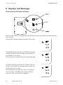
7.1 Switching On the Sunny Boy
1. Remove all covers from the PV array.
2. Switch on the AC main conductor breaker.
3. Turn the DC disconnect to position "1".
0
0
☑ The Sunny Boy performs an AFCI self-test.
AFCI self-test
Only the following types of Sunny Boy perform an AFCI self-test:
• SB 5000US-12
• SB 6000US-12
• SB 7000US-12
• SB 8000US-12
58
SB50US-80US-IA-en-37
Installation Manual
SMA America, LLC
Commissioning
☑ If the AFCI self-test is successful: The Sunny Boy goes into "Waiting" mode
and the green LED flashes.The "Waiting" mode ends when solar
irradiation reaches a certain level. The green LED lights up permanently
and the Sunny Boy feeds into the power distribution grid.
or
☑ If the AFCI self-test fails: The yellow LED flashes. The Sunny Boy repeats
the AFCI self-test until it is successful. Observe section 7.2 ”The Sunny Boy
Does Not Resume Operation” (page 59).
If the feed-in to the power distribution grid was interrupted by a detected AC failure and
then resumed, the inverter waits 5 minutes before feeding in again.
For this, the input voltage must be greater than the start voltage of the Sunny Boy. For the
corresponding values, see section 11 ”Technical Data” (page 91).
If the inverter is not able to feed into the power distribution grid three times in a row, it waits
10 minutes before the next attempt.
7.2 The Sunny Boy Does Not Resume Operation
DANGER
Danger to life due to high voltages in the PV system.
Risk of death or serious injury due to electric shock.
• Only qualified personnel may perform work on the PV array.
• Watch the display and the LEDs.
• Observe section 8 ”Displays and Messages” (page 62) and section 9 ”Troubleshooting”
(page 78).
No Operation Despite Sufficient Irradiation
1. Check whether the input voltage is sufficient. For the input voltage values, see 11 ”Technical
Data” (page 91).
2. If the input voltage is not sufficient, perform troubleshooting in the PV array and rectify the fault.
or
3. If the input voltage is sufficient, contact the SMA Service Line. Observe section 14 ”Contact”
(page 103).
SB50US-80US-IA-en-37
SB50US-80US-IA-en-37
59
Commissioning
SMA America, LLC
The Message "Disturbance AFCI" Is Displayed
An electric arc occurred in the PV system. The yellow LED is continuously lit up. The AFCI has been
triggered and operation of the Sunny Boy is permanently inhibited.
CAUTION
Danger of fire from electric arc
• Only test the AFCI for false triggering in the order described below.
• Do not deactivate the AFCI permanently.
1. Turn the DC disconnect to position "0".
☑ Wait for the display to go out.
0
0
0
0
2. Perform troubleshooting in the PV system:
Check all PV strings for the correct open-circuit voltage.
3. After the fault is rectified, restart the Sunny Boy: Turn
the DC disconnect to position "1".
☑ The Sunny Box starts and performs another
AFCI self-test.
4. If the following message appears on the display, knock on the enclosure lid: "Electric arc
detected — Knock to restart."
The message "Error AFCI. Knock to reset." appears for only 10 seconds. After
this, it is no longer possible to restart the unit by knocking on the enclosure lid.
• To restart the system, repeat step 1 to step 3.
60
SB50US-80US-IA-en-37
Installation Manual
SMA America, LLC
Commissioning
5. If the AFCI self-test is successful: The Sunny Boy goes into "Waiting" mode
and the green LED flashes.
☑ The "Waiting" mode ends when solar irradiation reaches a certain level.
The green LED lights up permanently and the Sunny Boy feeds into the
power distribution grid.
or
6. If the AFCI self-test fails: The Sunny Boy repeats the AFCI self-test until it is successful.
7. If the AFCI self-test continues to fail: Turn the DC
disconnect to position "0" and switch off the AC
disconnect switch to the inverter.
0
0
If the AFCI self-test fails permanently
• Contact the SMA Service Line. Observe section 14 ”Contact” (page 103).
In the event of inverter inspection
1. Turn the DC disconnect to position "0".
☑ The Sunny Boy switches itself off.
2. Disconnect the Sunny Boy on the AC side.
The Message "EarthCurrentMax“ Is Displayed
A ground fault is present in the PV array. The GFDI fuse is cleared.
1. Turn the DC disconnect to position "0" and switch
off the AC disconnect switch to the inverter.
0
0
2. Perform troubleshooting in the PV array.
SB50US-80US-IA-en-37
SB50US-80US-IA-en-37
61
Displays and Messages
SMA America, LLC
8 Displays and Messages
The Sunny Boy LED Status Indicators
Each Sunny Boy inverter is equipped with three LED status indicators that display the operating mode
of the inverter.
The green LED indicates standard operation of the inverter.
The red LED indicates the status of the GFDI fuse, located
inside the Sunny Boy. If this LED lights up, the GFDI fuse
has cleared or is not present.
The inverter does not feed into the power distribution grid.
The yellow LED indicates that there is a fault in either the
inverter or the PV plant. The inverter will not operate until
the fault has been corrected.
The possible error messages and causes are explained
later in section 9 ”Troubleshooting” (page 78) and in
section 8.2 ”LED Fault Indicators” (page 66).
62
SB50US-80US-IA-en-37
Installation Manual
SMA America, LLC
Displays and Messages
If the yellow LED and the red LED light up simultaneously,
the inverter has a ground fault.
The ground fault may also trip the GFDI fuse.
• Observe section 8.2 ”LED Fault Indicators”
(page 66).
In "Turbine" mode, all GFDI fuses are suspended.
8.1 LED Operation Indicators
Standby (Night)
The inverter is in standby mode. The input voltage is too low for operation.
Initialization
The inverter initializes. The power available from the PV array is not sufficient for standard operation.
Data transmission is not possible during initialization.
In the event of inclement weather or low solar irradiation, all LEDs may light up
simultaneously or flash. This is not an interference.
The inverter is attempting to initialize. The power available from the PV array is not sufficient
for standard operation.
SB50US-80US-IA-en-37
SB50US-80US-IA-en-37
63
Displays and Messages
SMA America, LLC
Start
The inverter calibrates the internal systems. The calibration lasts 10 seconds and the inverter begins
standard operation. If the inverter was manually placed into STOP mode, this status is displayed as
well.
Waiting
The inverter checks the grid requirements and whether enough voltage from the array is available to
feed into the power distribution grid.
If the feed-in to the power distribution grid was interrupted and then resumed, the inverter
always waits 5 minutes before feeding in.
If the inverter is not able to feed into power distribution grid three times in a row, it waits
10 minutes before the next attempt.
64
SB50US-80US-IA-en-37
Installation Manual
SMA America, LLC
Displays and Messages
Standard Operation
The inverter feeds into the power distribution grid in either "MPP", "Constant Voltage", or "Turbine"
mode.
"MPP" mode:
The Sunny Boy adjusts the voltage and the current from the PV array in order to receive the highest
possible PV output power.
"Constant Voltage" mode:
The array voltage is set to a fixed value. This value is set using the Sunny Boy Control or the Sunny
Data Software. The parameter name is
"V-Const":
This mode is suitable for using the inverter with fuel cells or small hydroelectric power plants.
"Turbine" mode:
This mode is suitable for using the inverter with a rectified DC generator and dynamic power
characteristic curve. The inverter can be adjusted to the form and slope of the power characteristic
curve of a specific generator. A small wind turbine system is a suitable generator for this.
Derating
The Sunny Boy can be operated with nominal power at an ambient temperature of up to +113 °F
(+45 °C). The Sunny Boy does remain operational at temperatures above +113 °F (+45 °C), but it
reduces the level of performance so as to protect the internal component parts from overheating.
Unwanted derating due to blocked fan inlets
Clean the fan inlets regularly.
SB50US-80US-IA-en-37
SB50US-80US-IA-en-37
65
Displays and Messages
SMA America, LLC
8.2 LED Fault Indicators
CAUTION
Risk of electric shock
Normally grounded conductors may be ungrounded and energized when a ground-fault
is indicated by the inverter.
• Check the PV-system for a ground fault and replace the ground fuse as described in
this document.
Ground Fault
If the yellow and red LEDs light up simultaneously, the inverter detected a ground fault. The inverter
will not restart automatically after detecting a ground fault.
• Locate the ground fault and rectify it. Observe section 9 ”Troubleshooting” (page 78).
• Then restart the inverter.
GFDI fuse
The ground fault may also trip the GFDI fuse.
In "Turbine" mode, all GFDI fuses are deactivated.
66
SB50US-80US-IA-en-37
Installation Manual
SMA America, LLC
Displays and Messages
Cleared GFDI Fuse
The GFDI fuse was cleared or is not present. This fuse protects the PV plant if a ground fault is present
in the PV array.
• Locate and rectify the ground fault. Observe section 9 ”Troubleshooting” (page 78).
• Then replace the GFDI fuse. The GFDI fuse is located in the fuse holder on the inverter board.
CAUTION
Risk of fire due to incorrectly dimensioned fuse.
Risk of injury due to fire.
• Only replace faulty fuses with fuses of the same type and size.
• The Sunny Boy is shipped with a Littelfuse KLKD 1 Amp, 600 V AC/DC type fuse.
Control System Fault
The yellow LED is continuously lit up. Operation of the Sunny Boy is permanently inhibited
The inverter no longer feeds into the power distribution grid and must be serviced by a qualified
service technician.
• Follow section 7.2 ”The Sunny Boy Does Not Resume Operation” (page 59) or contact SMA.
SB50US-80US-IA-en-37
SB50US-80US-IA-en-37
67
Displays and Messages
SMA America, LLC
Grid Failure
The yellow LED lights up for 5 seconds, goes out for 3 seconds, then flashes 2 times. This sequence is
repeated 3 times. As long as a grid failure continues to be present, this flashing code will repeat itself.
The flashing code can be caused by one of the following conditions:
• Grid undervoltage (< Vac Min)
• Grid overvoltage (> Vac Max)
• Grid underfrequency (< fac Min)
• Grid overfrequency (> fac Max)
• Sudden change in the power frequency or the grid voltage
DANGER
Danger to life due to high voltages in the inverter.
Risk of death or serious injury due to electric shock.
• Only qualified personnel may perform work on the inverter.
Monitor the status of the power distribution grid at the AC terminal blocks in the Sunny Boy and the
AC disconnect switch between the Sunny Boy and the power distribution grid.
68
SB50US-80US-IA-en-37
Installation Manual
SMA America, LLC
Displays and Messages
High DC Input Voltage
The yellow LED lights up for 5 seconds, goes out for 3 seconds, then flashes 4 times. This sequence is
repeated 3 times. If the status does not change, the flashing code repeats itself.
The inverter has detected a DC input voltage that is too high for safe operation.
NOTICE
Damage to the inverter due to high DC input voltage.
• Disconnect the inverter from the PV array immediately.
Inverter Interference
The yellow LED lights up for 5 seconds, goes out for 3 seconds, then flashes 5 times. The message is
repeated 3 times. If the status does not change, the flashing code repeats itself.
The inverter has detected an internal fault that interrupts standard operation. The inverter must be
maintained by a qualified service technician. Contact SMA.
SB50US-80US-IA-en-37
SB50US-80US-IA-en-37
69
Displays and Messages
SMA America, LLC
8.3 Status Messages on the LCD Display
The Sunny Boy is equipped with the LCD "Sunny Display" in the enclosure lid as standard.
Activation of the Background Illumination
Tapping on the enclosure lid activates the background illumination. Additional taps will scroll through
the display messages.
The background illumination shuts off automatically after 2 minutes.
INIT Messages
The inverter displays the following messages during
initialization:
After 6 seconds, the installed firmware versions of the
operation control unit (OCU) and the current control
system (SRR) are displayed.
Sunny Boy
WRXKuxxx
BFR Version x.xx.
SRR Version x.xx
Operation Messages
The LCD scrolls consecutively through all operation messages. Every message is displayed for
5 seconds. After all messages have been displayed, the LCD repeats all of the messages.
Message 1 "E-Today": Total energy generated today.
The current operating mode is displayed under this.
Message 2 "Gridtype”: System configuration of the
inverter and measured values of the voltage between the
conductor and the neutral conductor.
Message 3: Current AC power and current DC input
voltage.
70
SB50US-80US-IA-en-37
E-today 8.86kWh
Mode MPP
Gridtype - 208V
L1 120V L2 120V
Pac
Vpv
500W
380V
Installation Manual
SMA America, LLC
Message 4: Energy output accrued since the installation
of the inverter and the total operating hours.
Displays and Messages
E-Total 724.4kWh
h-total
512h
Knocking on the lid of the inverter takes you to the next display message.
Error Messages
If a fault occurs, the LCD switches into "Fault" mode and the background illumination is activated.
The upper line of the display shows one of the following fault types:
Interference
The Sunny Boy has detected a problem with the
frequency of the power distribution grid. The message
ends automatically as soon as the fault is rectified.
Interference is caused if a measured value exceeds a
preset limit.
The display shows the value of the fault (at:) as well as the
current value for the corresponding parameter (present:).
Disturbance
Fac-Bfr
at:
59.29Hz
present: 59.30Hz
Warning
The GFDI fuse is cleared. Warning messages display a
plant status that must be investigated. The inverter may be
operational despite a warning message.
Warning
GFDI Fuse Open
Error
The inverter has detected a problem with the internal
ROM. A fault status prevents a restart of the inverter until
the fault is rectified.
Error
ROM
Each error message is displayed for 5 seconds. After 5 seconds, the LCD scrolls through
the regular operation messages.
The error message will be displayed in the display sequence until the fault is rectified.
SB50US-80US-IA-en-37
SB50US-80US-IA-en-37
71
Displays and Messages
SMA America, LLC
8.4 Setting the Display Language
The LCD can display information in 1 of 4 different languages. The language is configured via 2 slide
switches that are located on the lower edge of the LCD.
1. Open the Sunny Boy as described in Section 6.3 ”Opening the Sunny Boy” (page 40).
2. Set the switches to the required language, as shown below.
Language
German
English
French
Spanish
Switch S2
B
B
A
A
Switch S1
B
A
B
A
3. Close the Sunny Boy as described in Section
6.8 ”Closing the Sunny Boy” (page 56).
☑ The display language is set.
8.5 Measuring Channels and Parameters
The communication options support a number of measuring channels and messages from the Sunny
Boy inverters. The following abbreviations are used:
OCU
SRR
Operation Control Unit
Current Control System (German abbreviation for
"Stromregelungsrechner")
The OCU and SRR are redundant processor control systems for the utility protection functions.
72
SB50US-80US-IA-en-37
Installation Manual
SMA America, LLC
Displays and Messages
8.5.1 Measurement Channels
Vpv:
Vpv Setpoint:
Iac:
Vac:
Vac L1:
Vac L2:
Fac:
Pac:
Vpv-PE:
Temperature:
Ipv:
Max Temperature:
Max Vpv:
I-dif:
Vfan:
E-Total:
h-Total:
h-on:
Power On:
Event-Cnt:
Serial Number:
CO2 saved:
Mode:
Grid Type:
Error:
SB50US-80US-IA-en-37
PV input voltage
MPPT DC target voltage
Grid current
Grid voltage L1 - L2
Grid voltage L1 - N
Grid voltage L2 - N
Power frequency
Power fed to grid
PV voltage to earth (for troubleshooting PV ground faults)
Temperature measured at IGBT module
PV current
Max temperature measured at IGBT
Max. PV input voltage
Fault current
Fan voltage
Total energy yield
Total operating hours
h-on displays how long sufficient DC voltage has been applied at the Sunny
Boy and how long the Sunny Boy has been in operation. The displayed
value contains the time when the Sunny Boy was unable to feed into the
power distribution grid due to the DC voltage being too low or due to
"STOP" mode.
Total number of system starts
Event counter
Serial number of the Sunny Boy
Amount of CO2 saved during the operating time
Current operating mode
Type of grid the Sunny Boy is connected to
Description of fault
SB50US-80US-IA-en-37
73
Displays and Messages
SMA America, LLC
8.5.2 Operating Mode
Stop:
Offset:
Waiting:
Grid monitoring:
MPP-Search:
MPP:
V-Const:
Derating:
Manual system stop
Offset calibration of the electronics (at start-up)
PV voltage is not high enough to start
Synchronizing to grid (at start-up)
MPPT range test (at start-up)
Sunny Boy is in MPP mode (standard operation)
Sunny Boy is in MPP mode with constant voltage
Reduction of the power fed into the grid due to increased cooling element
temperatures
Fault status relating to the grid. As soon as the cause of the fault is no longer
present, this fault will be reset automatically.
Inverter fault, user interaction required
System warning advising further investigation
Disturbance:
Error:
Warning:
8.5.3 Operating Parameters of the Sunny Boy
Changes to the preset parameters can negatively influence the operation and the
performance of the inverter
• Changes to the operating parameters must be made by trained qualified personnel.
Changes to the parameters labeled with * can lead to changes regarding conformity with IEEE 1547
and must be approved by the on site electric utility company and/or the responsible authority.
8.5.4 Operating Parameters of the Sunny Boy
l Name
Unit
AfciIsOn
Range
Standard
Password
Level
Description
yes/no
yes
Electrically
qualified
person
Arc fault circuit interrupter (AFCI)
AntiIsland-Ampl*
deg
0 ... 10
0
Electrically
qualified
person
Amplification of the anti-island
process
AntiIsland-Freq*
mHz
0 ... 2000
500
Electrically
qualified
person
Repetition rate of the anti-island
process
CO2-Fact
lb./kWh 0 ... 2
1.7
Electrically
qualified
person
The Sunny Boy evaluates the yield
and displays the approximate
amount of CO2 that the Sunny Boy
has saved.
This CO2 amount is calculated by
multiplying the generated kWh (Etotal) by the factor defined in the
parameter "CO2".
74
SB50US-80US-IA-en-37
Installation Manual
SMA America, LLC
Name
Displays and Messages
Unit
Default
Range
Standard
Password
Level
Description
USA/UL1741/
2005, OFF_Grid,
NON IEEE1547
USA/
UL1741/
2005
Electrically
qualified
person
Used for adjusting the country
specific parameter settings.
Note: After changing one of the
parameters marked with "*", the
parameter "default" changes to
"adjusted" automatically.
dFac-MAX*
Hz/s
0.005 ... 4
Electrically
0.5 (for
country setting qualified
person
USA/
UL1741/
2005)
Maximum "number of frequency
changes" before the anti-islanding
protection switches on
E_total
kWh
0 ... 200000
0
Electrically
qualified
person
Total energy yield of the inverter.
Changing the value may be
necessary if a Sunny Boy is replaced
and you wish to compare the data
obtained previously.
Fac-delta–*
Hz
0.2 ... 3
0.69 (for
Electrically
country setting qualified
USA/
person
UL1741/
2005)
Maximum permissible operating
frequency above and below 60 Hz.
Standard value is optimal for plants
< 30 kW.
Fac-delta+*
Hz
0 ... 4.5
0.49 (for
Electrically
country setting qualified
USA/
person
UL1741/
2005)
Fac-MinTripTime*
s
0.16 ... 300
0.16
Electrically
qualified
person
Switch-off time having fallen below
power frequency. The standard
value is optimal for plants < 30 kW.
1/0
0
Electrically
qualified
person
By setting this parameter to "1" you
can check the function of the fans.
This test turns the fans at maximum
speed.
0 ... 200000
0
Electrically
qualified
person
Total operating hours of the inverter.
Changing the value may be
necessary if a Sunny Boy is replaced
and you wish to compare the data
obtained previously.
Electrically
qualified
person
Default param.: Sets all parameters
to the standard value.
Reset Op.Data: Sets all parameters
to the standard values that are
displayed on the user level.
Reset errors: Resets all permanent
errors that lead to device
disconnection.
Fan-Test
h_Total
Memory Function
SB50US-80US-IA-en-37
h
no function, Default no function
param., Reset
Op.Data, Reset
errors
SB50US-80US-IA-en-37
75
Displays and Messages
Name
SMA America, LLC
Unit
Operating Mode
Range
Standard
Password
Level
Description
MPP-Operation,
Turbine, V-const,
Stop
MPP
Electrically
qualified
person
Operating modes of the Sunny Boy:
MPP-Operation: Sets the Sunny Boy
in Maximum Power Point Tracking
Mode
V-const: Constant Voltage Mode
(target value defined in "VconstSetval")
Turbine: Operating mode for wind
turbine systems
Stop: Disconnection from grid, no
operation
V-Const Setval
G
SB 5000-US SB 7000-US:
250 ... 600
SB 8000-US:
300 ... 600
600
Electrically
qualified
person
PV target voltage for constant
voltage operation. These
parameters only are important in the
event that the parameter "Operating
Mode" is set to "V-const".
Vac-Min*
%
0 ... 50
12
Electrically
qualified
person
Values are used to calculate the
lower limit of permissible AC
voltage.
Standard value is optimal for plants
< 30 kW. Standard value 12 results
in a trip value of 88 %, as the list of
trip limits shows.
Vac-Max*
%
0 ... 20
10
Electrically
qualified
person
Values are used to calculate the
upper limit of permissible AC
voltage.
Standard value is optimal for plants
< 30 kW. Standard value 10 results
in a trip value of 110 %, as the list of
trip limits shows.
Vac-Min-Fast*
%
0 ... 50
50
Electrically
qualified
person
Values are used to calculate the
lower limit of allowable AC voltage
for fast disconnection. Standard
value is optimal for plants < 30 kW.
Standard value 50 results in a trip
value of 50 %, as the list of trip limits
shows.
Vac-Max-Fast*
%
0 ... 20
20
Electrically
qualified
person
Values are used to calculate the
upper limit of allowable AC voltage
for fast disconnection. Standard
value is optimal for plants < 30 kW.
Standard value 20 results in a trip
value of 120 %, as the list of trip
limits shows.
Vac-Min-Recnet
%
0 ... 50
11.7
Electrically
qualified
person
Values are used to calculate the
lower and upper limits to reconnect
to the grid after a grid failure.
Vac-Max-Recnet
%
0 ... 20
5.83
Electrically
qualified
person
76
SB50US-80US-IA-en-37
Installation Manual
SMA America, LLC
Displays and Messages
Name
Unit
Range
Standard
Password
Level
Vpv-Start
G
SB 5000-US SB 7000-US:
250 ... 600
SB 8000-US:
300 ... 600
SB 5000-US - Electrically
SB 7000-US: qualified
300
person
SB 8000-US:
365
Description
Minimum DC voltage for the Sunny
Boy to connect to the grid.
8.5.5 Fixed Operating Parameters of the Sunny Boy
Name
Unit
Range
Standard
Description
Plimit
V
fixed
SB 5000-US: 5100
SB 6000-US: 6100
SB 7000-US: 7100
SB 8000-US: 8100
Upper limit of AC output power
SMA-SN
Serial number of the Sunny Boy
Software-OCU
Firmware version of the operation
control unit (OCU)
Software-SRR
Firmware version of the current
control system (SRR)
SB50US-80US-IA-en-37
SB50US-80US-IA-en-37
77
Troubleshooting
SMA America, LLC
9 Troubleshooting
9.1 General
Every inverter is checked prior to leaving the plant. If there are faults in the operation of the inverter,
perform the following steps to rectify the faults.
• Pay attention to Sunny Boy flashing codes. Look up the meaning of the flashing code being
displayed in section 7 ”Commissioning” (page 58).
• Monitor operating modes and error messages on the LCD of the Sunny Boy or via connected
PV plant monitoring. Look up the meaning of messages being displayed in section 8 ”Displays
and Messages” (page 62).
• Monitor the DC and AC voltage at the terminals in the inverter. Please observe all safety
precautions listed in the course of this manual.
• If the fault cannot be rectified, contact SMA Service Line. For contact data, see section
14 ”Contact” (page 103).
If it is necessary to return the Sunny Boy for maintenance, use the original box in order to prevent
shipping damage.
9.2 Error Messages
Error type
Interference
Error code
Ocu-Srr
Warning
Derating
Interference
Disturbance AFCI
Error
EarthCurMax-B
Error
EarthCurMax-S
Interference
EEPROM
Error
EEPROM p
Interference
EeRestore
78
SB50US-80US-IA-en-37
Description
Communication between micro-controllers is
interrupted.
The inverter reduces the output power due to high
internal temperatures.
Electric arc in the PV system. Eliminate the fault in
the PV system. Perform an AFCI self-test. Observe
section ”The Message "Disturbance AFCI" Is
Displayed” (page 60).
The ground current of the OCU between PV+ and
GND is outside of the tolerable range.
The ground current of the SRR between PV+ and
GND is outside of the tolerable range.
Transfer fault while reading or writing data from
the EEPROM. This data is not essential for safe
operation. This fault does not have any influence
on performance.
Data from the EEPROM are defective. The
operation of the inverter is permanently inhibited
as the data loss affects important functions of the
inverter. Contact SMA.
Internal interference.
Installation Manual
SMA America, LLC
Error type
Interference
Troubleshooting
Error code
Fac-Ocu, Fac-Srr
Warning
GFDI Fuse Open
Interference
Grid-Timeout, GridFault-S
Interference
Imax
Interference
Error
Interference
Error
K1-Close
K1-Open, K2-Open
MSD-FAC, MSD-Idif
MSD-VAC
Interference
Error
OFFSET
ROM
Interference
Interference
Shut-Down
Vac-Ocu, Vac-Srr
Description
The AC power frequency is exceeding the
permissible range. To prevent islanding, the
Sunny Boy disconnects itself from the power
distribution grid.
If the power frequency is within the tolerable
range and the error message "Fac-Ocu" or "FacSrr" continues to be displayed, contact SMA.
The GFDI fuse is cleared. Before replacing the
fuse, check the PV array for a ground fault error.
The system configuration cannot be detected
(208 V/240 V/277 V).
If a 277 V grid is configured: Check whether the
cables for L1 and N are located in the correct
connection terminals.
Overcurrent on the AC side. The current to the AC
grid exceeds the guidelines. The reason for this
may be severe grid interference. If "Imax"
appears frequently, check the AC grid. If you
require help, contact SMA.
Relay test failed. Contact SMA.
Internal measurement comparison fault:
The OCU and SRR values measured by the Sunny
Boy differ too strongly from one another.
Contact SMA.
Grid monitoring self-test failed.
The internal test of the Sunny Boy control system
firmware failed. If this fault occurs frequently,
contact SMA.
Continuous internal overcurrent.
The AC grid voltage is exceeding the permissible
range. The cause may be disconnection from the
power distribution grid or from an AC cable. To
prevent islanding, the Sunny Boy disconnects
itself from the power distribution grid.
If the error message "Vac-Ocu" or "Vac-Srr" is
displayed despite the grid voltage being within
the tolerable range, contact SMA.
SB50US-80US-IA-en-37
SB50US-80US-IA-en-37
79
Troubleshooting
Error type
Interference
Interference
SMA America, LLC
Error code
VacL1-Ocu, VacL2Ocu, VacL1-Srr, VacL2Srr
VpvMax
!PV Overvoltage!
Interference
Interference
!Disconnect DC!
Watchdog
XFMR
Description
Voltage is too high or too low on the indicated
branch.
The DC input voltage is exceeding the maximum
tolerable value.
Disconnect the DC line immediately.
Watchdog for operation control triggered.
The transformer is connected to the wrong grid.
Check the connection of the transformer.
For grounded Delta grids: Monitor whether the
grid grounding conductor is connected to
terminal L2.
Interference
XFMR_TEMP_F
Warning
XFMR_TEMP_W
80
SB50US-80US-IA-en-37
In the event of unbalanced load in 200 V and
240 V grids, swapping L1 and L2 may rectify the
fault.
High transformer temperature. The Sunny Boy
stops and the fans run at maximum speed.
After the reduction of the high transformer
temperatures, the Sunny Boy restarts. Monitor the
function of the fans.
Installation Manual
SMA America, LLC
Maintenance
10 Maintenance
Regular maintenance ensures a long operating life and optimal efficiency of the entire PV plant.
10.1 Cleaning the Fans
The Sunny Boy is fitted with two fans on its underside.
The fan intakes and handle covers should be cleaned periodically with a vacuum cleaner. For more
thorough cleaning, completely remove the fans.
NOTICE
Potential damage to the fans due to compressed air.
• Do not use compressed air for cleaning.
• Use a soft brush or a cloth for cleaning.
• Always remove the fans for cleaning.
1. Disconnect the Sunny Boy on the AC and DC sides.
2. Wait 5 minutes until the residual voltage has been drained and the fans are no longer turning.
Cleaning the Fan Guard
3. Remove the ventilation grids.
– Press both latches on the right edge of the fan
guard to the right using a screwdriver and
loosen from the bracket.
– Carefully remove the fan guard.
4. Clean the ventilation grid with a soft brush, a paint brush, a cloth or compressed air.
SB50US-80US-IA-en-37
SB50US-80US-IA-en-37
81
Maintenance
SMA America, LLC
Cleaning the Fans
5. Press the front latches backward and the rear latch
forward.
6. Remove the fan by pulling it slowly and carefully downward.
7. Unlock and remove the plug.
The cables of the fans are long enough to disconnect the plug in the inside of the Sunny Boy.
8. Remove the fan.
9. Clean the fan with a soft brush, a paintbrush, or a cloth.
10. After cleaning, mount the fans and the ventilation grids in reverse order.
11. Check the function of the fans as described in section "Fan Test" on page 84.
82
SB50US-80US-IA-en-37
Installation Manual
SMA America, LLC
Maintenance
10.2 Cleaning the Handle Covers
For optimal heat dissipation of the device, the handle covers must be clean. Clean the handle covers
regularly.
NOTICE
Insects can enter the Sunny Boy
Potential damage to the Sunny Boy.
• The handle covers must not be removed permanently, otherwise the inverter is not
protected against the ingress of insects.
1. Remove the handle covers. To do this, put your
finger up into the space between the handle covers
and the enclosure and pull the handle covers to the
side
2. Clean the handle covers with a soft brush or a
paintbrush.
3. Re-secure the handle covers on the inverter. The
side on which they are to be mounted is stated on
the inside of the handle covers ("links/left" and
"rechts/right").
10.3 Checking the DC Disconnect
In the case of normal use, the DC Disconnect does not require any maintenance.
Operating the switch cleans the contacts and extends the life of the DC Disconnect.
It is recommended, though not compulsory, to:
• Check the DC disconnect regularly.
• Activate the DC disconnect 10 times in a row once a year.
Operating the switch cleans the contacts and extends the life of the DC disconnect.
0
SB50US-80US-IA-en-37
0
0
0
SB50US-80US-IA-en-37
83
Maintenance
SMA America, LLC
10.4 Fan Test
In the event of frost, the fan cannot be inspected
The fans are not activated under 32 °F (0 °C).
You can check the operation of the fans in 2 ways:
• Set the parameter "Fan Test" in installer mode to "1". To do this, use the Sunny Data, Sunny Data
Control, Sunny Boy Control, or the Sunny WebBox.
or
• Set the jumper on the sequential control system board. The jumper for checking the fans is
included in the scope of supply of the Sunny Boy.
Setting the Parameter
1. Ask for the installer password from SMA Service Line. See "Contact" on page 103.
2. Set the "Fan Test" parameter to "1" in installer mode.
3. Check the air flow of the fans.
– The Sunny Boy draws in cold air through the fans and lets it out again through the handle
covers.
– Pay attention to unusual sounds.
4. After checking the fans, set the parameter "Fan Test" back to "0".
84
SB50US-80US-IA-en-37
Installation Manual
SMA America, LLC
Maintenance
Setting the Jumper
The Sunny Boy recognizes the jumpers after the restart.
All LEDs must be off prior to a restart.
1. Disconnect the Sunny Boy on the AC and DC sides. Wait 5 minutes until the residual voltage
has been drained.
2. Open the Sunny Boy as described in section 6.3 ”Opening the Sunny Boy” (page 40).
3. Insert the jumper supplied into the slot on the sequential control system board shown below.
4. Close the Sunny Boy as described in section 6.8 ”Closing the Sunny Boy” (page 56).
5. Check the air flow of the fans.
– The Sunny Boy draws in cold air through the fans and lets it out again through the handle
covers.
– Pay attention to unusual sounds.
6. After checking the fans, remove the jumper.
10.5 Exchanging the Fuses
CAUTION
Risk of fire due to incorrectly dimensioned fuse.
Risk of injury due to fire.
• Only replace faulty fuses with fuses of the same type and size.
SB50US-80US-IA-en-37
SB50US-80US-IA-en-37
85
Maintenance
SMA America, LLC
10.5.1 Exchanging the GFDI Fuse within the Sunny Boy
1. Disconnect the Sunny Boy on the AC and DC sides.
2. Wait 5 minutes until the residual voltage has been drained and the fans are no longer turning.
1. Open the Sunny Boy as described in section 6.3 ”Opening the Sunny Boy” (page 40).
2. Replace the fuse (A).
For the correct position of the fuse, observe section "DC Input Grounding" on page 48.
A
3. Completely insert the fuse into the terminal.
4. Close the Sunny Boy as described in section 6.8 ”Closing the Sunny Boy” (page 56).
5. Switch the AC and DC disconnect switches back on.
10.5.2 Exchanging PV String Fuses within the DC disconnect
1. Disconnect the Sunny Boy on the AC and DC sides.
2. Wait 5 minutes until the residual voltage has been drained.
3. Open the DC disconnect as described in section 6.4 ”Opening the DC Disconnect” (page 41).
4. Replace the fuse (1, 2, 3, or 4).
4
1
3
COMBINED
2
4
1
3
COMBINED
2
1
2
3
4
UNGROUNDED
1
2
3
4
UNGROUNDED
GROUNDING
ELECTRODE
CONDUCTOR
GROUNDED
L1
L2
N
GROUNDED
5. Close the DC disconnect as described in section 6.9 ”Closing the DC Disconnect” (page 57).
6. Switch the AC and DC disconnect switches back on.
86
SB50US-80US-IA-en-37
Installation Manual
SMA America, LLC
Maintenance
PV String Fuse Sizing
If the fuses are designed too small, they may open too early and cause interference. If fuses are
designed too large, they do not provide the required protection as they open too late.
For PV plants, the minimum and maximum size of a fuse connected in series is specified by the
electrical nominal sizes of a PV module and by UL and the National Electrical Code. Contact the
manufacturer of the PV modules in order to obtain the corresponding nominal sizes of the PV string
fuses.
The minimum sizes of fuses and cables are calculated using the Short Circuit Current Rating (Isc) of
the PV module. The National Electrical Code stipulates that all fuses and cables are designed to be
at least 1.56x as large as the Isc of the PV module being used in the plant.
The correct size of the PV string fuse is specified by calculating 1.56x the Isc (of the PV module) and
then rounding this up to the nearest standard size for fuses.
For example, if the Isc of the PV module is 6.9 Adc, then the size of the PV string fuses is
determined as follows: 1.56 x 6.9 = 10.76
The nearest standard size for fuses would be a 12 A and 600 Vdc fuse.
The size of a string fuse may not be greater than the maximum nominal value of a PV
module fuse. Observe the data sheet of the PV module. If no maximum size for fuses is
stated, contact the manufacturer of the PV module.
DC Disconnect Requirements
National Electrical Code 690.15-18 enables the use of fuse holders as a suitable medium for
disconnecting PV arrays for maintenance. Additional DC disconnects external to the inverter may be
required by the local authority having jurisdiction.
WARNING
Electric arc and electric shock when removing the fuses under load.
Risk of death or serious injury.
• Do not remove any fuses when the inverter is under load.
PV String Fuses
The DC disconnect is shipped with 15 A, 600 V DC fuses in the fuse holders. The maximum nominal
size for string fuses in the DC disconnect is 20 A at 600 V DC.
When dimensioning the fuses, observe the National Electrical Code® 690.8 and 690.9.
SB50US-80US-IA-en-37
SB50US-80US-IA-en-37
87
Maintenance
SMA America, LLC
10.6 Testing and Replacing the DC Varistors
Only the following inverter types are equipped with DC varistors:
SB 5000US-12/SB 6000US-12/SB 7000US-12/SB 8000US-12.
In regions where storms or other DC overvoltages frequently occur, the DC varistors loose their
functionality if the PV plant is not equipped with an additional overvoltage protection. To ensure that
the functionality of the DC varistors remains at a constant level, SMA recommends in such cases to
replace the DC varistors after an operating time of 10 years with new ones.
NOTICE
No protection against overvoltage due to faulty or missing varistors
Destruction of the inverter is possible.
• Do not operate the inverter with faulty varistors or no varistors at all.
• Replace faulty varistors immediately.
Position
A
B
Description
Terminals for DC varistors
Fuse holders for fuse extractor with string fuses
1. Disconnect the Sunny Boy on the AC and DC sides.
2. Wait 5 minutes for the components to cool down.
3. Open the DC disconnect as described in Section 6.4 ”Opening the DC Disconnect” (page 41).
DANGER
High voltages at the DC terminals with connected PV modules
Risk of death or serious injury when touching the DC terminal.
• Do not touch any live component of the DC terminals.
88
SB50US-80US-IA-en-37
Installation Manual
SMA America, LLC
Maintenance
4. Check the DC varistors (A) for discoloration and visible damage.
• If one of the DC varistors is discolored or damaged, replace all DC varistors:
DANGER
Danger to life due to short circuits in the DC varistors
Death or serious injury due to electric shock
• Check whether current is flowing the DC cables.
Tip: Use a current clamp to measure the current.
5. Disconnect the DC varistors:
– Disconnect the string connectors of all ungrounded DC cables from the PV array.
– Remove the four fuse extractors with the string fuses from the fuse holders (B) of the DC
disconnect.
– Remove the four string fuses from the fuse extractors.
– Insert the four fuse extractors without the string fuses into the fuse holders (B) of the DC
disconnect.
6. Ensure that no voltage is present at the DC varistors.
• If no voltage is present, replace all DC varistors:
Only use spare parts from SMA
• Always replace the entire set of DC varistors.
• Order number in Section 12 ”Spare Parts and Accessories” (page 101).
– Insert the insertion tool into the rectangular
opening of the terminal.
– Remove the DC varistor.
SB50US-80US-IA-en-37
SB50US-80US-IA-en-37
89
Maintenance
SMA America, LLC
– Insert the new DC varistor into the terminal.
– Pull the insertion tool out of the rectangular
opening of the terminal.
7. Ensure that all DC varistors in the terminals are securely in place.
8. Re-insert all string fuses into the DC disconnect:
– Remove the four fuse extractors without string fuses from the fuse holders (B) of the DC
disconnect.
– Equip the four fuse extractors with functional string fuses.
– Insert the four fuse extractors with the string fuses in the fuse holders (B) of the DC
disconnect.
9. Close the DC disconnect as described in Section 6.9 ”Closing the DC Disconnect” (page 57).
10. Re-connect the string connectors of all ungrounded DC cables to the PV array.
☑ Testing and replacement of the DC varistors is completed.
90
SB50US-80US-IA-en-37
Installation Manual
SMA America, LLC
Technical Data
11 Technical Data
11.1 Sunny Boy 5000-US (SB 5000US and SB 5000US-12)
PV Array Connection
Maximum MPP voltage
Nominal operating voltage
Range of input operating voltage
Maximum generator input power
Maximum DC power
PV start voltage
Maximum DC input current
Maximum input short-circuit current
Maximum utility backfeed current to PV array
DC voltage ripple
250 V … 480 V
310 V
250 V … 600 V
6 250 W
5 300 W
300 V
21 A
36 A
50 A AC
< 10 %
Grid Connection
AC operating voltage range at 208 V nominal value
AC operating voltage range at 240 V nominal value
AC operating voltage range at 277 V nominal value
AC operating frequency range
AC frequency, nominal value
Maximum continuous AC output power
Current THD
Maximum continuous AC output current at 208 V
Maximum continuous AC output current at 240 V
Maximum continuous AC output current at 277 V
Maximum output failure current
Maximum output overcurrent protection
Synchronization of inrush current
Trip limit accuracy
Trip time accuracy
Power consumption at night
183 V … 229 V
211 V … 264 V
244 V … 305 V
59.3 Hz … 60.5 Hz
60 Hz
5 000 W
<4%
24 A
20.8 A
18 A
57.6 A
50 A
9.23 A
±2 %
±0.1 %
0.1 W
General Data
Inverter technology
Cooling concept
SB50US-80US-IA-en-37
True sine, low-frequency transformer
OptiCool
SB50US-80US-IA-en-37
91
Technical Data
SMA America, LLC
Efficiency
SB 5000-US
98
92
90
VPV = 250 V DC
88
VPV = 310 V DC
97
95
480
250
VPV = 480 V DC
VMPP [V]
86
0.2
0.0
0.4
0.6
* weighted in accordance with CEC-operating points
94
weighted Eta* [%]
Efficency [%]
96
1.0
0.8
Output power / Rated power
Range of output power factor
Output power factor, nominal value
Peak inverter efficiency
CEC weighted efficiency at 208 V AC
CEC weighted efficiency at 240 V AC
CEC weighted efficiency at 277 V AC
0.95 … 1.0
0.99
96.8 %
95.5 %
95.5 %
95.5 %
Ambient Conditions
Ambient temperature range SB 5000US
Ambient temperature range SB 5000US-12
− 13 °F … +113 °F
( − 25 °C … +45 °C)
− 40 °F … +113 °F
( − 40 °C … +45 °C)
Mechanical Data
Width x height x depth
Weight
Noise emission
Electronics degree of protection
92
SB50US-80US-IA-en-37
183⁄8 in. x 241⁄8 in. x 91⁄16 in.
(468 mm x 613 mm x 242 mm)
147 lb. (67 kg)
44 dB(A)
NEMA 3R
Installation Manual
SMA America, LLC
Technical Data
11.2 Sunny Boy 6000-US (SB 6000US and SB 6000US-12)
PV Array Connection
Maximum MPP voltage
Nominal operating voltage
Range of input operating voltage
Maximum generator input power
Maximum DC power
PV start voltage
Maximum DC input current
Maximum input short-circuit current
Maximum utility backfeed current to PV array
DC voltage ripple
250 V … 480 V
310 V
250 V … 600 V
7 500 W
6 400 W
300 V
25 A
36 A
50 A AC
< 10 %
Grid Connection
AC operating voltage range at 208 V nominal value
AC operating voltage range at 240 V nominal value
AC operating voltage range at 277 V nominal value
AC operating frequency range
AC frequency, nominal value
Maximum continuous AC output power
Current THD
Maximum continuous AC output current at 208 V
Maximum continuous AC output current at 240 V
Maximum continuous AC output current at 277 V
Maximum output failure current
Maximum output overcurrent protection
Synchronization of inrush current
Trip limit accuracy
Trip time accuracy
Power consumption at night
183 V … 229 V
211 V … 264 V
244 V … 305 V
59.3 Hz … 60.5 Hz
60 Hz
6 000 W
<4%
29 A
25 A
21.6 A
57.6 A
50 A
9.23 A
±2 %
±0.1 %
0.1 W
General Data
Inverter technology
Cooling concept
SB50US-80US-IA-en-37
True sine, low-frequency transformer
OptiCool
SB50US-80US-IA-en-37
93
Technical Data
SMA America, LLC
Efficiency
SB 6000-US
98
92
90
VPV = 250 V DC
88
VPV = 310 V DC
97
95
480
250
VPV = 480 V DC
VMPP [V]
86
0.2
0.0
0.4
0.6
* weighted in accordance with CEC-operating points
94
weighted Eta* [%]
Efficency [%]
96
1.0
0.8
Output power / Rated power
Range of output power factor
Output power factor, nominal value
Peak inverter efficiency
CEC weighted efficiency at 208 V AC
CEC weighted efficiency at 240 V AC
CEC weighted efficiency at 277 V AC
0.95 … 1.0
0.99
97.0 %
95.5 %
95.5 %
96.0 %
Ambient Conditions
Ambient temperature range SB 6000US
Ambient temperature range SB 6000US-12
− 13 °F … +113 °F
( − 25 °C … +45 °C)
− 40 °F … +113 °F
( − 40 °C … +45 °C)
Mechanical Data
Width x height x depth
Weight
Noise emission
Electronics degree of protection
94
SB50US-80US-IA-en-37
183⁄8 in. x 241⁄8 in. x 91⁄16 in.
(468 mm x 613 mm x 242 mm)
147 lb. (67 kg)
44 dB(A)
NEMA 3R
Installation Manual
SMA America, LLC
Technical Data
11.3 Sunny Boy SB 7000-US (SB 7000US and SB 7000US-12)
PV Array Connection
Maximum MPP voltage
Nominal operating voltage
Range of input operating voltage
Maximum generator input power
Maximum DC power
PV start voltage
Maximum DC input current
Maximum input short-circuit current
Maximum utility backfeed current to PV array
DC voltage ripple
250 V … 480 V
310 V
250 V … 600 V
8 750 W
7 500 W
300 V
30 A
36 A
50 A AC
< 10 %
Grid Connection
AC operating voltage range at 208 V nominal value
AC operating voltage range at 240 V nominal value
AC operating voltage range at 277 V nominal value
AC operating frequency range
AC frequency, nominal value
Maximum continuous AC output power
Current THD
Maximum continuous AC output current at 208 V
Maximum continuous AC output current at 240 V
Maximum continuous AC output current at 277 V
Maximum output failure current
Maximum output overcurrent protection
Synchronization of inrush current
Trip limit accuracy
Trip time accuracy
Power consumption at night
183 V … 229 V
211 V … 264 V
244 V … 305 V
59.3 Hz … 60.5 Hz
60 Hz
7 000 W
<4%
34 A
29 A
25.3 A
57.6 A
50 A
9.23 A
±2 %
±0.1 %
0.1 W
General Data
Inverter technology
Cooling concept
SB50US-80US-IA-en-37
True sine, low-frequency transformer
OptiCool
SB50US-80US-IA-en-37
95
Technical Data
SMA America, LLC
Efficiency
SB 7000-US
98
92
90
VPV = 250 V DC
88
VPV = 310 V DC
97
95
480
250
VPV = 480 V DC
VMPP [V]
86
0.2
0.0
0.4
0.6
* weighted in accordance with CEC-operating points
94
weighted Eta* [%]
Efficency [%]
96
1.0
0.8
Output power / Rated power
Range of output power factor
Output power factor, nominal value
Peak inverter efficiency
CEC weighted efficiency at 208 V AC
CEC weighted efficiency at 240 V AC
CEC weighted efficiency at 277 V AC
0.95 … 1.0
0.99
97.1 %
95.5 %
96.0 %
96.0 %
Ambient Conditions
Ambient temperature range SB 7000US
Ambient temperature range SB 7000US-12
− 13 °F … +113 °F
( − 25 °C … +45 °C)
− 40 °F … +113 °F
( − 40 °C … +45 °C)
Mechanical Data
Width x height x depth
Weight
Noise emission
Electronics degree of protection
96
SB50US-80US-IA-en-37
183⁄8 in. x 241⁄8 in. x 91⁄16 in.
(468 mm x 613 mm x 242 mm)
141 lb. (64 kg)
46 dB(A)
NEMA 3R
Installation Manual
SMA America, LLC
Technical Data
11.4 Sunny Boy SB 8000-US (SB 8000US and SB 8000US-12)
PV Array Connection
Maximum MPP voltage
Nominal operating voltage
Range of input operating voltage
Maximum generator input power
Maximum DC power
PV start voltage
Maximum DC input current
Maximum input short-circuit current
Maximum utility backfeed current to PV array
DC voltage ripple
300 V … 480 V
345 V
300 V … 600 V
10 000 W
8 600 W
365 V
30 A
36 A
50 A AC
< 10 %
Grid Connection
AC operating voltage range at 240 V nominal value
AC operating voltage range at 277 V nominal value
AC operating frequency range
AC frequency, nominal value
AC maximum continuous output power at 240 V
AC maximum continuous output power at 277 V
Current THD
Maximum continuous AC output current at 240 V
Maximum continuous AC output current at 277 V
Maximum output failure current
Maximum output overcurrent protection
Synchronization of inrush current
Trip limit accuracy
Trip time accuracy
Power consumption at night
211 V … 264 V
244 V … 305 V
59.3 Hz … 60.5 Hz
60 Hz
7 680 W
8 000 W
<4%
32 A
29 A
61.7 A
50 A
14.32 A
±2 %
±0.1 %
0.1 W
General Data
Inverter technology
Cooling concept
SB50US-80US-IA-en-37
True sine, low-frequency transformer
OptiCool
SB50US-80US-IA-en-37
97
Technical Data
SMA America, LLC
Efficiency
SB 8000-US
98
92
90
VPV = 300 V DC
88
VPV = 345 V DC
97
95
480
300
VPV = 480 V DC
VMPP [V]
86
0.2
0.0
0.4
0.6
* weighted in accordance with CEC-operating points
94
weighted Eta* [%]
Efficency [%]
96
1.0
0.8
Output power / Rated power
Range of output power factor
Output power factor, nominal value
Peak inverter efficiency
CEC weighted efficiency at 240 V AC
CEC weighted efficiency at 277 V AC
0.95 … 1.0
0.99
96.5 %
96.0 %
96.0 %
Ambient Conditions
Ambient temperature range SB 8000US
Ambient temperature range SB 8000US-12
− 13 °F … +113 °F
( − 25 °C … +45 °C)
− 40 °F … +113 °F
( − 40 °C … +45 °C)
Mechanical Data
Width x height x depth
Weight
Noise emission
Electronics degree of protection
183⁄8 in. x 241⁄8 in. x 91⁄16 in.
(468 mm x 613 mm x 242 mm)
147 lb. (67 kg)
49 dB(A)
NEMA 3R
Specifications subject to change without notice. Values under nominal conditions.
98
SB50US-80US-IA-en-37
Installation Manual
SMA America, LLC
Technical Data
11.5 DC Disconnect
Maximum DC input current
Maximum DC short-circuit current
Maximum system voltage
Maximum nominal size for string fuses
Maximum AC operating current
Dimensions W x H x D
Weight
Electronics degree of protection
30 A
36 A
600 V
20 A
34 A
7 7⁄8 in. x 12 13⁄64 in. x 7 31⁄64 in.
(200 mm x 310 mm x 190 mm)
8 lb. (3.5 kg)
NEMA 3R
Specifications subject to change without notice.
SB50US-80US-IA-en-37
SB50US-80US-IA-en-37
99
Technical Data
SMA America, LLC
11.6 Trip Limits/Trip Times
Frequency
Nominal
Frequency
60 Hz
Trip Limit
Trip Frequencies
Trip Times
> 60.5 Hz
< 57.0 Hz … 59.8 Hz
(standard 59.3 Hz)
60.45 Hz … 60.55 Hz
56.95 Hz … 59.85 Hz
(standard 59.25 Hz …
59.35 Hz)
56.95 Hz … 57.05 Hz
max. 0.1602 s
adjustable, 0.16 s … 300 s
(standard max. 0.1602 s)
< 57.0 Hz
max. 0.1602 s
Voltage
Nominal
Voltage
Trip Limit
208 V
50 %
240 V
277 V
Trip Voltages
ConductorNeutral
Conductor*
57.6 V … 62.4 V
Trip Voltages
ConductorConductor*
Trip Times
99.8 V … 108.2 V
max. 0.1602 s
88 %
103.2 V … 108.0 V 178.9 … 187.2 V
max. 2.002 s
110 %
129.6 V … 134.4 V 224.6 V … 233.0 V
max. 1.001 s
120 %
50 %
141.6 V … 146.4 V 245.4 V … 253.8 V
57.6 V … 62.4 V 115.2 V … 124.8 V
max. 0.1602 s
max. 0.1602 s
88 %
103.2 V … 108.0 V 206.4 V … 216.0 V
max. 2.002 s
110 %
129.6 V … 134.4 V 259.2 V … 268.8 V
max. 1.001 s
120 %
50 %
141.6 V … 146.4 V 283.2 V … 292.8 V
133.0 V … 144.0 V Not applicable
max. 0.1602 s
max. 0.1602 s
88 %
238.2 V … 249.3 V
max. 2.002 s
110 %
299.2 V … 310.2 V
max. 1.001 s
120 %
326.9 V … 337.9 V
max. 0.1602 s
* The intervals result from the measuring accuracies listed below.
Accuracy
Trip limits: ±2 % of nominal grid voltage
Trip time: ±0.1 % of nominal trip time
Trip frequency: ±0.1 % of nominal frequency
100
SB50US-80US-IA-en-37
Installation Manual
SMA America, LLC
Spare Parts and Accessories
11.7 Torque Values and Cable Sizes
Terminal
Gray AC & DC terminal blocks (Weidmüller),
inverter
Green AC & DC terminal blocks (Phoenix),
inverter
Gray terminal blocks for wires that are not used
in the configuration of the AC voltage
(Weidmüller)
Green terminal blocks for wires that are not used
in the configuration of the AC voltage (Phoenix)
AC & DC terminal blocks, DC disconnect
Combined terminal block, DC disconnect
Grounding conductor terminal block, DC
disconnect
Screws for fastening the Sunny Boy and the DC
disconnect to the wall mounting bracket and
closing the DC disconnect cover
Cover screws
Torque
18 in-lb. (2 Nm)
Cable Size
10 … 6 AWG
40 in-lb. (4.5 Nm)
22 in‑lb. (2.5 Nm)
22 in-lb. (2.5 Nm)
8 … 6 AWG
10 AWG
---
15 in-lb. (1.7 Nm)
---
15 in-lb. (1.7 Nm)
Spring terminal
15 in-lb. (1.7 Nm)
10 … 6 AWG
10 … 6 AWG
10 … 6 AWG
44 in-lb. (5 Nm)
---
53 in-lb. (6 Nm)
---
12 Spare Parts and Accessories
If needed, you can order these from SMA or your SMA specialty retailer.
Spare Parts
Name
DC varistors*
Ventilation grid
Brief Description
1 set varistors (DC), including
insertion tool
"Right and left" ventilation grid
set as a replacement part
SMA Order Number
SB-VDC-US01
45-7202
* only SB 5000US-12/SB 6000US-12/SB 7000US-12/SB 8000US-12
Accessories
Name
Power Balancer set
RS485 retrofit kit
Bluetooth retrofit kit
SB50US-80US-IA-en-37
Brief Description
Retrofit kit for the Power
Balancer function
RS485 interface
Bluetooth communication
interface
SMA Order Number
PBL-SBUS-10-NR
485USPB-NR
BTPBINV-NR
SB50US-80US-IA-en-37
101
Compliance Information
SMA America, LLC
13 Compliance Information
FCC Compliance
This device complies with Part 15 of the FCC Rules. Operation is subject to the following conditions:
1. This device may not cause harmful interference, and
2. This device must accept any interference received, including interference that may cause
undesired operation.
NOTE: This equipment has been tested and found to comply with the limits for a Class A & B
digital device, pursuant to Part 15 of the FCC Rules. These limits are designed to provide reasonable
protection against harmful interference in a residential installation. This equipment generates, uses,
and can radiate radio frequency energy and if not installed and used in accordance with the
instructions, may cause harmful interference to radio communications. However, there is no guarantee
that interference will not occur in a particular installation. If this equipment does cause harmful
interference to radio or television reception, which can be determined by turning the equipment off
and on, the user is encouraged to try to correct the interference by one or more of the following
measures:
• Reorient or relocate the receiving antenna.
• Increase the separation between the equipment and the receiver.
• Connect the equipment into an outlet on a circuit different from that to which the receiver is
connected.
• Consult the dealer or an experienced radio/TV technician for help.
The user is cautioned that changes or modifications not expressly approved by
SMA America, Inc. could void the user’s authority to operate this equipment.
IC Compliance
This device complies with Industry of Canada licence-exempt RSS standard(s). Operation is subject
to the following two conditions:
• This device may not cause interference, and
• This device must accept any interference, including interferences that may cause undesired
operation of the device.
102
SB50US-80US-IA-en-37
Installation Manual
SMA America, LLC
Contact
14 Contact
If you experience technical problems with our products, please contact SMA Service Line. We require
the following information in order to provide you with the necessary assistance:
• Inverter type
• Type and number of modules connected
• Type of communication
• Interference or warning messages from Sunny Boy
• Sunny Boy display message
SMA Solar Technology America, LLC
6020 West Oaks Blvd, Ste 300
Rocklin, CA 95765
Tel. +1 916 625 0870
Tel. +1 877-MY SMA TECH
Tel. +1 877 697 6283 (toll free, available for USA, Canada, and Puerto Rico)
Fax +1 916 625 0871
[email protected]
www.SMA-America.com
SMA Solar Technology Canada Inc.
2425 Matheson Blvd E, 8th Floor
Mississauga, ON L4W 5K5, Canada
Tel. +1 877 506 1756 (toll free, available for Canada)
[email protected]
www.SMA-Canada.ca
SB50US-80US-IA-en-37
SB50US-80US-IA-en-37
103
SMA America, LLC
4.""NFSJDB1SPEVDUJPO--$
XXX4.""NFSJDBDPN
Installation Manual
SB50US-80US-IA-en-37
104