1
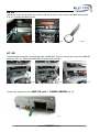
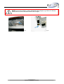
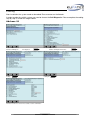
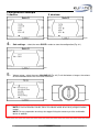
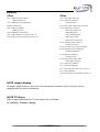
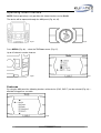
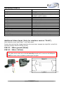
Version 1.10
Installation manual
multimedia adapter
Audi
Article-ID
38137
38137-2
38217
38217-1
38218
38218-1
Audi
A4 8K
A5 8T
A6 4F
A7 4G
A8 4E
A8 4H
Q5 8R
Q7 4L
(For vehicles with MMI High 2G, 3G)
www.kufatec.de
Kufatec GmbH & Co. KG • Dahlienstr. 15 • 23795 Bad Segeberg • e-mail: [email protected]
Content
General advice ........................................................................................................................................... 1
Safety Instructions ...................................................................................................................................... 2
References of legal regulations for operation ............................................................................................. 2
Wiring diagram ........................................................................................................................................... 4
Control lines ................................................................................................................................................ 4
Installation instruction MMI 2G ................................................................................................................... 5
Interface connection MMI 2G ..................................................................................................................... 6
Connection video loom MMI 2G ................................................................................................................. 8
Connection video loom MMI 2G – RVC available ...................................................................................... 9
Connection in case of factory fitted analog TV MMI 2G ........................................................................... 10
Installation instruction MMI 3G ................................................................................................................. 11
Interface connection MMI 3G ................................................................................................................... 12
Connection video loom MMI 3G ............................................................................................................... 14
Coding ...................................................................................................................................................... 17
Setup video interface ................................................................................................................................ 18
Operating video interface ......................................................................................................................... 21
General advice
While developing this product, your personal safety combined with the best operating service, modern
design and an up-to-date production technique was especially taken into account.
Unfortunately, despite the utmost care injuries and/or damages might occur due to improper installation
and/or use.
Please read the attached instruction manual completely with great care and keep it!
All articles of our production line pass through a 100 % check - for your safety and security.
We reserve the right to carry out technical changes which serve the improvement at any time.
According to each article and purpose, it is sometimes necessary to check each country’s legal
regulations before installing and starting the unit.
In case of guarantee claims, the device has to be sent back to the seller in the original packaging with
the attached bill of purchase and detailed defect‘s description. Please pay attention to the manufacturer‘s
return
requirements (RMA). The legal warranty directions are valid.
The guarantee claim as well as the operating permission becomes invalid due to: Der Garantieanspruch
und auch die Betriebserlaubnis erlischt durch:
a) unauthorized changes to the device or accessories which have not been approved or carried out
by the manufacturer or its partners
b) opening the device‘s frame
c) device‘s repairs carried out by one‘s own
d) improper use / operation
e) brute force to the device (drop, wilful damage, accident etc.)
1
Safety Instructions
Installation requires special knowledge.
Do not install the unit yourself. For safe and reliable installation, consult a dealer having special
knowledge.
• Never use bolts or nuts from the car’s safety devices for installation. If bolts or nuts from the
steering wheel ,brakes or other safety devices are used for installation of the unit, it may cause an
accident.
•Use the unit with a DC 12V negative ground car. This unit cannot be used in large trucks which
use a DC 24V battery. If it is used with a DC 24V battery, it may cause a fire or accident.
• Avoid installing the unit in following places: - Where it would hinder your safe driving. - Where it
could damage the car’s fittings.
• This unit is only for use in the following vehicles. Only connections described within this
instruction guide are allowed or required to use for installation.
• For damage impact caused by faulty installation, unsuitable connections inappropriate vehicles
Kufatec GmbH & Co. KGassumes no liability.
• We advise you that these units process datas out of the MOST - protocol from the vehicle. As
the supplier of this device we don‘t know the overall system you are working with. If our device
causes damage due to other changes made by to the vehicle Kufatec GmbH assumes no liability.
• Kufatec GmbH & Co. KG supplier do not guaranty the use of the product for changing’s within a
new vehicle series.
• If the car manufacturer’s don‘t agree with the installation of our device by reason of warranty the
Kufatec GmbH & Co. KG assumes no liability. Please check conditions and warranty before you
begin the installation.
• Kufatec GmbH & Co. KG supplier reserves the right to change the device specifications without
notice.
NOTE: The road traffic has to have your full attention.
Operations should only be done by suitable traffic and weather situations. The volume need to be
set that you are still able to realise acoustic warn signals (Police, fire brigade).
• Errors and changes excepted.
References of legal regulations for operation
Only use this unit in the intended domain.
If you use it in a foreign domain, if the unit is not installed properly, or if the unit will be reconstructed, the
guarantee will expire.
2
Multimedia adapter
•
•
•
•
Easy installation, No cutting of wires necessary
Factory fitted functions do not get affected at all
OEM-menu driven operation by MMI panel (Only interface version “Plus”)
Audio output through the vehicle speakers - no installation of additional speakers necessary
Note MMI 2G: In case the vehicle is not factory fitted with rear view camera (RVC) the
displayinterface needs to be replaced. A displayinterface with FBAS input is needed. After
replacing the displayinterface the component protection needs to be removed.
Please contact your local Audi dealer.
Detailed information please see page 21
NOTE: Before installing the multimedia system you need to check whether the car is retrofitted
with an interface not developed by Kufatec GmbH & Co. KG. In case a non-Kufatec interface is
fitted we are not able to guaranty the absolute operation of the multimedia system. You may
need to remove the non-Kufatec interface.
NOTE: Fiber optical looms MUST NOT BE CRACKED! The recommended radius
for fitting is 40 mm.
In case of incorrect fitting we are not able to guaranty the absolute operation of the multimedia
system.
Fitting location for end devices
Device fitting (DVD, DVB-T) supposed to be on various locations within the back of the vehicle. In case
of fitting the device in the front (e.g. DVD-Player) an additional AV loom will be needed.
Note: While fitting 2 devices at the same time (DVD Player + DVB-T) an Y-junction for fitting both
control lines (Kufatec article-ID 35551) is needed (Fig. 1).
Fig.1
Accessories
Article-ID 35601 – Y-junction jack for connecting control line + infrared eye (remote) at the same time
Article-ID 36482 – Y-junction for connecting control line + infrared eye (remote) at the same time
Article-ID 37613 – AV wiring (extension) 550cm
3
Wiring diagram
Fig.2
* If factory fitted
ACC (Blue) –
NOTE: For vehicles with factory analog TV (MMI 2G) please see
installation notes page 10.
Connection to the ACC loom of the multimedia device (DVD/ DVB-T)
In case the multimedia device doesn’t have any ACC loom the ACC loom of the
interface will stay without any functionality.
NOTE: Power supply looms of DVD/ DVB-T must not be connected to the ACC loom of
the video interface! The video interface will be destroyed!
This loom has to be protected while using an additional fuse of 1Ampere.
Control lines
For operating the devices (DVD, DVB-T) through the original MMI panel (Only for interface „Plus“) a
specific control line is needed (table below).
Device
Kufatec article-ID.
Device
Kufatec article-ID.
DVD Player Ampire DVX 101
35550
DVB-T Ampire DVBT 52
35549
DVD Player MP 410U
35550
DVB-T Ampire DVBT 200
35549
DVD Player BOA 85700
35550
DVB-T Ampire DVBT 400
35549-1
DVD Player AIV Car DVD Player
35550
DVB-T Alpine TUE-T150DV
35547
DVD Player DVD 145
35552
DVB-T Dietz 1491
35553
DVD Player 500 U
35550
DVB-T Dietz 1492
36923
DVB-T Zemex D90-2G
38265
DVB-T DAS M21
38400
DVB-T Zemex D100
35549-1
iPod Video Interface Alpine KCE
425i
35552
DVD Changer Zemex DVC62
38505
DVB-T Kufatec HR-5A, 5AX
38775
4
Installation instruction MMI 2G
For vehicles WITHOUT factory fitted rear view camera
Fig. 3
1 – Radiobox A4 8K, A5 8T, A6 4F, A8 4E
2 – Radiobox Q7 4L
3 – Displayinterface A4 8K, A5 8T
4 – Displayinterface A6 4F, A8 4E, Q7 4L
For vehicles WITH factory fitted rear view camera
Fig. 4
1 – Radiobox A4 8K, A5 8T, A6 4F
2 – Radiobox Q7 4L
3 – RVC – control unit Q7 4L
4 – RVC – control unit A4, A5, A6 4F, A8 4E
Location Radiobox
The fitting location of the radiobox can be verify within the vehicle.
A4 8K, A5 8T, A6 4F, A8 4E
Q7 4L
Fig.5
Fig.6
5
Fig.7
Interface connection MMI 2G
Fiber optic cable
The connection will be completed plug & play on the back of the radiobox.
Fig.8
Remove the original fiber optical cable of the radiobox (Fig. 9). Join the original fiber optical connector to
the female connector of the delivered loom (Fig. 10).
Fig.9
Fig.10
Put the optical connector of the delivered loom to the radiobox (Fig. 11). ). Figure 12 is showing the final
connection of the multimedia interface.
Fig.11
Fig.12
6
Power
The connection will be completed plug & play on the back of the radiobox. Remove the original power
connector of the radiobox (Fig. 13). Join the original connector to the female connector of the delivered
loom (Fig. 14).
Fig.13
Fig.14
Put the connector of the delivered loom to the radiobox (Fig. 15). Figure 16 is showing the final
connection of the multimedia interface.
Fig.15
Fig.16
Join the 18-pole connector as well as the fiber optical to the interface (Fig. 17). Join the connections for
audio- video as well as the control line (Fig. 18). Note: The control line will only be needed in case of
interface version “Plus”.
Fig.17
Fig.18
Fig.19
Single loom Blue (Fig.19) - connecting to the ACC loom of the device (DVD/ DVB-T).
BEFORE connecting the loom make sure it is the ACC loom of the DVD/ DVB-T device!
In case the multimedia device doesn’t have any ACC loom the ACC loom of the interface will stay
without any functionality.
NOTE: Power supply looms of DVD/ DVB-T must not be connected to the ACC loom of
the video interface! The video interface will be destroyed!
7
Connection video loom MMI 2G
For vehicles WITHOUT factory fitted rear view camera
Wire the loom into the front of the vehicle (Fig.20 - 22).
Fig.20
Fig.21
Fig.22
A4 8K, A5 8T
Remove the climate control with suitable tools (Fig. 23). Remove the CD-changer (Fig. 24). Loosen the
necessary screws of the displayinterface and remove it (Fig. 25).
Fig.23
Fig.24
Fig.25
A6 4F, A8 4E, Q7 4L
Loosen the necessary screws of the glove box (Fig. 26, 27). Remove the displayinterface (Fig. 28).
Fig.26
Fig.27
8
Fig.28
Connect the video loom to the displayinterface (Fig. 29).
In case the vehicle is not factory fitted with rear view camera (RVC) the displayinterface
needs to be replaced – Kufatec Article-ID. 35600
Notes please see page 21
Fig.29
Connection video loom MMI 2G – RVC available
For vehicles WITH factory fitted rear view camera
Location RVC control unit
Depending of the vehicle the RVC-control unit is fitted on different fitting locations.
A4 8K, A5 8T, A6 4F, A8 4E
Q7 4L
Fig.30
Fig.31
Connect the video loom to the RVC-control unit - FAKRA BROWN (Fig. 32).
Fig.32
9
Connection in case of factory fitted analog TV MMI 2G
For vehicles with factory fitted analog TV tuner.
NOTE: Not suitable for MMI 3G
Location analog TV tuner
The TV tuner is located with the infotainment rack of the vehicle (Fig. 33).
Item number 38186-2 (Fig. 34).
Fig.33
Fig.34
Factory fitted analog tuner needs to be removed.
Join wiring 38186-2 with the connections of the factory fitted TV-Tuner.
TV Tuner connector Red
FAKRA GREEN
Fig.35
Fig.36
Fig.37
Join the 18-pole connector of the loom 38186-2 as well as the original fiber optical connector (TV tuner)
to the interface (Fig. 37).
10
Installation instruction MMI 3G
Fig. 38
1 – Radiobox A4, A5, A6 4F, A8 4E, Q5 8R
2 – Radiobox Q7 4L
3 – Radiobox A8 4H
4 – MMI 3G unit A4/ A5, A8 4H, Q5 8R, Q7 4L
5 – MMI 3G unit A6 4F
5 – DVD-Changer A8 4H
Audi A4 8K, A5 8T, A6 4F, Q5 MMI 3G
Loosen the necessary screws of the trunk cover on the left hand side (Fig. 39). The radiobox is located
behind the cover (Fig. 41).
Fig.39
Fig.40
Fig.41
Audi Q7 4L MMI 3G
Remove the trunk cover on the right hand side. The radiobox is located behind (Fig. 43).
Fig.42
Fig.43
11
Audi A8 4H
Remove the trunk cover on both sides. Remove the cover of the rear seats (Fig. 46).
Fig.44
Fig.45
Fig.46
Loosen the necessary screws of the bracket of the comfort control unit (Fig. 47, 48). The radiobox is
located behind (Fig. 49).
Fig.47
Fig.48
Fig.49
Interface connection MMI 3G
Fiber optic cable
The connection will be completed plug & play on the back of the radiobox.
Remove the original fiber optical cable of the radiobox (Fig. 50). Join the original fiber optical connector
to the female connector of the delivered loom (Fig. 51).
Fig.50
Fig.51
12
Put the optical connector of the delivered loom to the radiobox (Fig. 52). Figure 53 is showing the final
connection of the multimedia interface.
Fig.52
Fig.53
Power
With the connection of 2 new wires to the Quadlock connector of the radiobox you will complete the
fitting of the power supply. Please see Fig 55. In order to achieve a proper connection we recommend
both crimping and soldering the new wires.
Brown (Ground) – PIN 17
Red (Steady plus) – PIN 18
Fig. 54
Fig.55
Join the 18-pole connector as well as the fiber optical to the interface (Fig. 56). Join the connections for
audio- video as well as the control line (Fig. 57). Note: The control line will only be needed in case of
interface version “Plus”.
Fig.56
Fig.57
Fig.58
Single loom Blue (Fig.58) - connecting to the ACC loom of the device (DVD/ DVB-T).
BEFORE connecting the loom make sure it is the ACC loom of the DVD/ DVB-T device!
In case the multimedia device doesn’t have any ACC loom the ACC loom of the interface will stay
without any functionality.
NOTE: Power supply looms of DVD/ DVB-T must not be connected to the ACC loom of
the video interface! The video interface will be destroyed!
13
Connection video loom MMI 3G
Wire the loom into the front of the vehicle (Fig. 59 - 61).
Fig.59
Fig.60
Fig.61
A4 8K, A5 8T, Q5 8R, Q7 4L
Remove the MMI 3G unit (Fig. 62, 63).
Fig.62
Fig.63
A6 4F, A8 4E
Loosen the necessary screws of the glove box (Fig. 64, 65).
Fig.64
Fig.65
14
A8 4H
Loosen the screw of the center consol cover (Fig. 66) as well as the screws of the MMI 3G unit cover
(Fig. 67). Remove the MMI 3G unit.
Fig.66
Fig.67
Fig.68
A7 4G
Climate control needs tob e removed by using suitable tools (Fig. 69). Loosen the screw of the MMI 3G
head unit (Fig. 71). Remove the MMI 3G unit of the center console.
Fig.69
Fig.70
Connect the video loom to the MMI 3G unit – FAKRA GREEN (Fig. 72).
Fig.72
15
Fig.71
NOTE: In case the vehicle is factory fitted with DVD-changer (e.g. A8 4H, A7 4G) the
video loom has to be connected to the DVD-changer.
Fig.73
Fig.74
16
Coding
After installation the system needs to be coded. Please contact an Audi dealer.
In order to code the vehicle system you need to choose the Self-Diagnosis. Please complete the coding
step by step as shown on images below.
Address 19
Vehicle Self-Diagnosis
Self diagnosis
Coding
Address 19 Diagnostic interface
Coding list
TV-Tuner needs to be set from not coded to coded - confirmation
17
Setup video interface
1.
Push the MEDIA button – TV-Tuner needs to be selected (Fig. 75, 76).
Fig.75
2.
Fig.76
Select the menu 90- SYS-SETUP – Push the rotate controller (Fig. 77).
Fig.77
3.
Fig.78
Setup for device operation
1C: Configuration Single- or Dual-control
1C00: Control of ONE device – Dual-control is deactivated
The device has to be selected through menu 2C
In case of TWO devices the first device has to be selected through menu 1C01 to 1Cxx
(please see table).
2C: Multimedia devices for Dual-control
Selecting devices through the menu 2C00 to 2Cxx
The
*
symbol within the MMI screen is displaying the current configuration.
NOTE: In case of one device 1C00 has to be set first before selecting the device
through the 2Cxx menu.
18
Configuration example
1 device
2 devices
Fig.79
4.
Fig.80
Safe settings – select the menu SAVE in order to store the configuration (Fig. 81).
Fig.81
5.
Volume setup – select the menu VOLUME UP (Fig. 82). Push the button as long as the volume
of the multimedia device has arrived to maximum.
Fig.82
Fig.83
NOTE: In case of interface version „Basic“ the volume needs to be set by using the remote
control.
NOTE: For easy operation we always do suggest fitting the remote eye of the multimedia
device in addition.
19
Devices
1Cxx
2Cxx
1C01 – DVD Player Ampire DVX101
2C01 – DVB-T Dietz 1492/ 1493
DVD Player MP 410U
2 C02 – DVB-T KTC dual3000
1 C02 – DVD Player AIV Car DVD Player
DVB-T Dietz 1491
DVD Player BOA 85700
2 C03 - DVB-T Ampire DVB-T 200, 400 2G/ 3G
1C03 – DVD Player DVD145
2 C04 – DVB-T Ampire DVB-T 52
DVD Player 500U
DVB-T Zemex DVB-T 100
1C04 - DVB-T Alpine TUE-T150DV
DVB-T Bullit HD 4G
1C05 – DVB-T DAS M21 (from Interface SW 1.13)
DVB-T ASUKA ARA-HD
1C06 – DVD changer Zemex DVC62 (from SW 1.18)
DVB-T Ampire 55-HD
DVB-T Kufatec HR-5A, 5AX
2 C05 – DVD Player Ampire DVX101
DVD Player MP 410U
2 C06 – iPod Video Interface Alpine KCE 425i
2 C07 – DVD Player AIV Car DVD Player
DVD Player BOA 85700
2 C08 – DVD Player DVD145
DVD Player 500U
2 C09 – DVB-T Alpine TUE-T150DV
DVB-T Alpine TUE T200
2 C10 – DVB-T Zemex D90-2G
2C11 – DVD Player DVD500U
2C12 – DVB-T DAS M21 (from Interface SW 1.13)
2C13 – DVB-T HD-DVB-T
2C14 – DVD changer Zemex DVC62 (from SW 1.18)
NOTE image display
For proper image display in some cases the end devices need to be set to 16:9 screen. Please
complete within the menu of the device.
NOTE TV Norm
While using the MMI panel the TV norm needs to be set Europe:
TV > SETUP > TV-Norm > Europe
20
Operating video interface
NOTE: Device operating is only possible with video interface version PLUS.
The device will be operated through the MMI panel (Fig. 84, 85).
Fig.84
Fig.85
Press MEDIA (Fig. 86) – select the TV-Tuner source (Fig. 87).
Up to 65 channels can be choosen.
Fig.86
Fig.87
Features
By using the MMI panel the following functions of the device (DVD, DVB-T) can be selected (Fig. 88). –
detailed listing please see table.
Fig.88
21
Operating features
Display MMI screen
Feature
80 – OK
80 - Power
80 – Radio
OK-button remote
ON/ OFF
Switching between TV-mode and digital radio (only
available in specific regions)
Switching to the second device
Channel scanning
Exit- button remote
Arrow up- button remote
Arrow down- button remote
Arrow left- button remote
Arrow right- button remote
Next track
Previous track
Volume multimedia device up
Volume multimedia device down
USB source
Menu-button remote
Setup configuration multimedia adapter
80 – VideoInput
80 – Search
80 – Exit
80 – Up
80 – Down
80 – Left
80 – Right
80 – Next
80 – Previous
80 – Volume Up
80 – Volume Down
80 – USB
80 – Setup
90 – Sys. Setup
Additional Video Input (Only for interface version “PLUS”)
Note: No processing of audio signals – only video signals
Remove the housing of the 18-pole connector of the main loom. Integrate the single PIN’s of the RCA connector (Kufatec article-ID 35570) (Fig. 89).
PIN 15 – Video ground (Black)
PIN 16 – Video (Yellow)
The video source needs to be selected manually through the AV source on the MMI panel.
NOTE: No auto switch available by choosing the rear gear.
Fig.89
22
Fig.90
Replacement Displayinterface
NOTE: before replacing the displayinterface all MMI components needs to be updated to the
latest software index. Please get in contact with your local Audi dealer.
Neede update CD
Model
CD-part number
A6 4F, A8 4E, Q7 4L
4L0 998 961
A4 8K, A5 8T
8K0 998 961
Procedure
Disconnect battery
replace interface
connect battery again
Turn ignition on
remove component protection (Get in contact with your local Audi
dealer – online connection is required)
Address 07
remove component protection (In some cases the coding machine is
asking a blocking time – These time needs to be elapsed completely)
Additional coding Address 07
Country code, Vehicle – Note down the values of the old interface
Copy the values into
the new interface
Additional adaption channels
Channel 01 – MMI device list (ACC, AAS, PDC, MFSW, TPMS, RVC)
Channel 02 – Options within CAR menu (Left hand drive, battery status)
Channel 11 – Additional MMI features (logbook, clima comfort, aux heating)
Channel 12 – Phone version (1 for PR-Nr. 9ZW
--- 2 for PR-Nr. 9ZF)
Channel 13 – Protocol setting: 0 = A6, A8, Q7 /
8191 = A4 8K, A5 8T
Channel 111 – MMI start for activating the configurated values
NOTE: Kufatec GmbH & Co. KG has got no influence in deleting the component protection. In
case it is not possible to delete the protection please get in contact with [email protected].
23