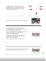
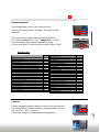
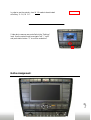
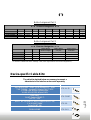
1
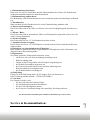
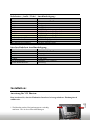
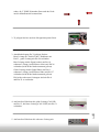
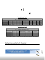
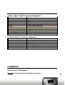
Inhaltsverzeichnis:
Seite
1
IF-VAGPHAVDC
Inhaltsverzeichnis ....................................................................................................................... 2
Sicherheitshinweise .................................................................................................................... 3
Service / Kommunikation........................................................................................................... 4
Lieferumfang .............................................................................................................................. 4
Produktbeschreibung .................................................................................................................. 5
Installation ............................................................................................................................... 6-7
Funktionsweise und Steuerung................................................................................................ 8-9
Tastenbelegungen ..................................................................................................................... 10
Endgeräte spezifische Kabelsätze ............................................................................................ 11
Y-Kabelsätze ........................................................................................................................... 12
Seite
Sicherheitshinweise:
2
Technische Daten ..................................................................................................................... 13
1. Einbauanleitung durchlesen:
Bitte lesen Sie sich vor dem Einbau und der Inbetriebnahme des Gerätes alle Sicherheitsinstruktionen und Bedienhinweise aufmerksam durch.
2. Einbauanleitung aufbewahren:
Die Bedienungs- und Sicherheitshinweise zum eventuellen späteren Nachschlagen aufbewahren.
3. Warnhinweise:
Bitte beachten Sie alle Warnhinweise die in der Einbauanleitung enthalten sind.
4. Wasser und Feuchtigkeit:
Das Gerät sollte nicht in der Nähe von Wasser oder einer Feuchtigkeitsquelle betrieben werden.
5. Wärme / Hitze:
Das Gerät sollte nicht in unmittelbarer Nähe von Wärmequellen aufgestellt werden (wie z.B.
auch Leistungs-Endstufen).
6. Stromversorgung:
Das Gerät sollte nur am +12 Volt Bordnetz betrieben werden.
7. Anschluss/Stromversorgung:
Das Gerät nur an einem +12 Volt Bordnetz verwenden und auf einen ordentlichen Masseanschluss achten.
8. Eindringen von Gegenständen oder Flüssigkeit:
Bitte Achten Sie darauf, dass keine Gegenstände oder Flüssigkeiten in das Geräteinnere eindringen können (Kurzschlussgefahr)!
9. Reparaturen:
Sie sollten geschultes Fachpersonal aufsuchen, wenn:
• ein Stecker oder eine Steckverbindung beschädigt wurde
• Kabel beschädigt sind
• Objekte in das Gerät gefallen oder Flüssigkeit eingedrungen ist
• das Produkt Feuchtigkeit ausgesetzt war
• das Gerät nicht normal arbeitet oder deutliche Änderungen im
Betriebsverhalten zu beobachten sind
• das Produkt/Gehäuse beschädigt ist.
10. Bedienung:
Führen Sie keine Bedienung durch, die Sie längere Zeit vom Strassenverkehr/Verkehrsgeschehen ablenkt – UNFALLGEFAHR!!!
11. Garantie:
Die Garantie erlischt, wenn:
• Sie das Gerät oder das Gehäuse öffnen
• Sie selbstständig Reparaturen durchführen
• Sie das Gerät unsachgemäss nutzen
• das Gerät eine Gewalteinwirkung oder mutwillige Zerstörung aufweist
Seite
Service & Kommunikation:
3
Wir übernehmen keine Haftung für Schäden am Kraftfahrzeug sowie Personen.
Alle unsere Produkte werden unter strenger Qualitätskontrolle hergestellt. Jedes Gerät wird
vor dem Versand getestet. Falls dennoch Probleme auftreten oder Sie technische Fragen haben, kontaktieren Sie uns direkt unter:
Neben der ständigen Produktverbesserung und Änderung werden parallel hierzu auch ständig
die Bedienungsanleitungen zu den Geräten überarbeitet und dem neuesten Stand angepasst.
Um die für Ihr vorhandenes Gerät entsprechenden Informationen und
Unterstützung richtig liefern zu können, fügen Sie bitte allen
Anfragen folgende Informationen hinzu:
Kaufdatum, Name & Anschrift, Artikelnummer und Fahrzeugmodell
Lieferumfang:
•
Bedienungsanleitung
iPod® ist ein eingetragenes Markenzeichen der Apple Computer, Inc.
iPod® is a registered trademark of Apple Computer, Inc.
Dieses Interface ermöglicht den Anschluss einer beliebigen
externen Videoquelle (z.B. DVD Player, DVB-T Tuner) an
ein Phaeton Bildschirm Navigationssystem von VW.
Ein weiteres Merkmal ist die Möglichkeit der Steuerung
der angeschlossenen Videoquelle(n) über die Tasten der
Navigation.
Seite
Artikel:
Funktion:
4
Produktbeschreibung:
Kabelsatzes „Audio / Video“ Anschlussbelegung:
Kabelfarben/Stecker:
● Schwarz:
● Schwarz:
● Rosa:
● Grün:
● Rot:
● Schwarz:
● Gelb:
● Schwarz:
● Cinch-Stecker Gelb:
● Cinch-Stecker Rot:
● Cinch-Stecker Schwarz:
Anschluss/Belegung:
Masse
Masse
Y - Signal
C - Signal
AUDIO Signal Ausgang (rechts)
AUDIO Masse Ausgang (rechts)
AUDIO Signal Ausgang (links)
AUDIO Masse Ausgang (links)
VIDEO-Eingang
AUDIO-Eingang (rechts)
AUDIO-Eingang (links)
Interface Kabelsatz Anschlussbelegung:
Kabelfarben/Stecker:
● Rot:
● Schwarz:
● Gelb:
● Blau:
●● Weiß/Schwarz:
3,5mm Klinkenbuchse:
Anschluss/Belegung:
+12V DC ( Dauerstrom )
Masse
CAN-HI
CAN-LOW
Ausgang +12V (100mA)
Steuerung
Installation:
Anweisung für VW Phaeton:
1. Zierblenden um das Navigationssystem vorsichtig
entfernen. Wie in der rechten Abbildung zu
Seite
5
Bitte beachten Sie, dass der Einbau des Interfaces bei ausgeschalteter Zündung durch
zuführen ist.
sehen, die 5 TORX Schrauben lösen und das Gerät
aus der Mittelkonsole herausziehen.
2. 32 poligen Stecker aus dem Navigationssystem lösen.
3. Anschlussbelegung für 32 poligen Stecker:
Rosa Leitung am “Audio/Video” Kabelsatz mit
Pin 23 , grüne Leitung mit Pin 24 verbinden.
Rote Leitung (Audio Signal rechts) mit Pin 10,
schwarze Leitung (Audio Masse rechts) mit Pin 26
verbinden (beide Kabel sind zusammen gefasst).
Gelbe Leitung (Audio Signal links) mit Pin 11,
schwarze Leitung (Audio Masse links) mit Pin 27
verbinden (beide Kabel sind zusammen gefasst).
Die beiden schwarzen Leitungen sind mit Pin 8
und Pin 25 zu verbinden.
5. Am Interface Kabelsatz die schwarze Leitung mit
Seite
6
4. Am Interface Kabelsatz die gelbe Leitung (CAN-HI)
mit Pin 15, die blaue Leitung (CAN LOW) mit Pin 31
verbinden.
Masse (Stromstecker Pin8), die rote Leitung mit 12V
Dauerplus (Stromstecker Pin7) verbinden.
6. Die 3,5mm Mini Klinke Buchse am Kabelsatz
des Interfaces dient zur Gerätesteuerung. Hier
wird das entsprechende Steuerkabel angeschlossen
(z.B. „STK-AL25“ für DVD Alpine Geräte).
Zusätzlich kann der Y-Adapter „CABLE-415“
(separat erhältlich) eingesetzt werden um
IR-Empfänger der Videoquelle parallel zum
Interface anschließen zu können.
(Details zu Steuerkabel siehe Seite 9 und 10)
STK-xxxx Kabelsatz
7. Video / Audio Cinchkabel (nicht im Lieferumfang enthalten)
mit den drei Cinchbuchsen am Interface und der Videoquelle
verbinden.
8. Das System zurück in der Mittelkonsole befestigen.
Funktionsweise und Steuerung:
Seite
Um die Steuerung der angeschlossenen Geräte zu
aktivieren muss das System zunächst durch das betätigen
der „AUDIO/TV“ und dann der „TV“ Taste in den
TV Modus versetzt werden.
7
Aktivierung:
Gerätezuweisung:
Über die Videotextebene findet die Gerätezuweisung statt.
Durch drücken der Softkey Taste „Videotext“ wird die
Videotextebene aktiviert.
Über dem mittleren Drehknopf wird der dreistellige Geräte
RC Code eingegeben (z.B. das erste Gerät > „101“,
das zweite Gerät > „203“). Durch das drücken des mittleren
Drehknopfs wird der jeweils eingestellte RC Code gespeichert.
Nach eingabe der RC Codes wird die Ebene über den Softkey
„Zurück“ wieder verlassen.
Geräte RC Codes:
Model
Model
RC Code:
DVD USB, MP410, MP412, AD212U, DVP-1000M, DVP-900HD
DVBT2007, Dietz 1491/V
AMPIRE DVB-T100
DVB2008, TRT400
DVDC CKO DVC10
DVD-Changer CKO- DVC 6M , Yamakawa DVD-Changer
DVBT NL, SENERGY, C-KO DVBT-1080, Axion DVBT 500
DVD ADJQ-DVDRD, PYLE PLTD24, Veba, Carmedien CM06
DVD 1/2 DIN (NO NAME)
1
2
3
4
5
6
7
8
9
DVD Alpine RUE - 4201
DVD Alpine RUE - 4158;TUE-T150DV
DVBT Eastern SE863-T
iPod® Vlink
DVBT ZENEC ZE-DVBT25
V-HUB VPA-B222R Alpine Radio
V-HUB VPA-B222R Alpine DVD
DVD Necvox DVA-3206
Analog-TV Alpine TUE-T112P
Analog-TV TRT-003
BOA-DVD 85700 /AIV, C-KO 412
DVD Visteon VXM2200
10
11
12
13
14
15
16
17
18
19
20
21
DVBT Quantum QTM10
DVD Elite ELT-900XU Novosonic
DVDC CkO MPC6
DVD-TIXXON (No Name)
HD-Player 3,5“ MVIX MV-5000U
DVD Axion VDV-402
DVD Bullit CDVD12
DVD ZENEC ZE-080
DVBT Ampire DVBT200
DVBT&DVD USB Digitaldynamic Multiplayer
iPod Alpine KCE-425I
A-TV TVT-765
Emperor Mini DVBT
DVBT Carmedien DVB423
DVBT M-DTV-201-0
DVDC Pioneer XDV-P6 (Reserviert)
DVD Phonocar VM 015 (USB/SD)
Hirschmann DVBT / Visteon DVBT
HD Microlab - Pocket X Div 25 (2,5 Zoll HD P. Tixxon)
DVB-T D80
DAS / Dietz 1492 DVB-T
DVBT Ampire DVBT50
RC Code:
22
23
24
25
26
27
28
29
30
31
32
33
34
35
36
37
38
39
40
41
42
43
Steuerung:
Um die Steuerung nutzten zu können muss über den Softkey
Seite
8
Die Steuerung der Videoquelle(n) erfolgt über diverse Tasten
der Navigation. Die Umschaltung der Steuerung zwischen den
Geräten erfolgt über Softkey Taste „Sender verfolgen“:
AN = Gerät 1 , AUS = Gerät 2 .
Ausführliche Tastenbelegungen siehe Seite 10.
„A 1-6 / M 1-6“ die ebene A 1-6 aktiviert werden.
Die „Einstellung“ Ebene kann zu Menü Steuerung
der Videoquelle verwendet werden. Hierbei dient
der mittlere Drehknopf zur „links“ / „rechts“
Navigation und die Stationstaste „5“ ist mit dem
Befehl „Enter“ belegt.
Seite
9
Tastenbelegungen:
Tastenbelegung Teil 1
●─● Phaeton Navigation ●─●
Model
1
2
DVD PLAYER
ON/OFF
MENU PBC
3
4
MENU
5
TITLE
PLAY
6
7
STOP
TRACK -
8
9
10
TRACK +
↑
↓
↓
DVB-T TUNER
ON/OFF
EPG
SETUP
INFO
ENTER
EXIT
CH -
CH +
↑
I-POD® CONTROL
ON/OFF
SHUFFLE
BULB
REPEAT
ENTER
PLAY
TRACK -
TRACK +
↑
↓
ANALOG TUNER
ON/OFF
FM
ADJUST
DISPLAY
SCAN
MUTE
CH -
CH +
VOL +
VOL -
Tastenbelegung Teil 2
●─● Phaeton Navigation ●─●
Model
9*
10*
Softkey Taste
„Sender verfolgen“
Softkey Taste
„TV / AV“
Softkey Taste
„Autostore“
DVD PLAYER
→
←
SWITCH DEVICE
AV
ZOOM / DISC
DVB-T TUNER
→
←
SWITCH DEVICE
AV
SCAN
I-POD® CONTROL
→
CH +
←
SWITCH DEVICE
EJECT
-
CH -
SWITCH DEVICE
SCAN
SCAN
ANALOG TUNER
* Mittlere Drehknopf Funktion in „Einstellungen“ Ebene (unterer rechter Drehknopf hat keine Funktion) .
Endgeräte spezifische Kabelsätze:
STK-AL25
10
Kabelsatz
Seite
Hersteller, Typ
DVD Alpine RUE – 4201, DVD Alpine RUE – 4158,
TUE-T150DV, Analog-TV Alpine TUE-T112P
V-HUB VPA-B222R Alpine Radio,
V-HUB VPA-B222R Alpine DVD,
DVB-2007,
DVBT Eastern SE863-T,
DIETZ - 1491
DVBT NL, SENERGY, DVBT Ampire DVB-T200,
C-KO DVBT-1080,
Axion DVBT 500
STK-D2007
STK-NL
DVB-ALPINE
STK-SV4
Analog-TV TRT-003
STK-SV6
DVD-SAN
STK-SV7
DVB-2008,
DVB-HDIN,
TRT400
DVD-CKO DVC10, DVDC CKO MPC6, ALPINE KCE-425I,
DVD-PYLE, DVD-VEBA, DVD-PS, ZENEC, RC-03,
DVD Changer CKO- DVC 6M , Yamakawa DVD-Changer,
DVD 1/2 DIN (NO NAME), ZENEC ZE-080
DVD-USB, AMPIRE DVB-T100, I-POD® V-LINK,
DIETZ DVD – 85700/AIV, DVP-1000M, MP410, MP412,
AD212U, DVP-1000M, DVP-900HD, C-KO 412,
DVD Axion VDV-402,DVD Elite ELT-900XU Novosonic
DVBT Quantum QTM10
DVBT Emperor DTR-1203
STK-SV8
STK-UNI
STK-USB
STK-QTM10
STK-SV42
Die unten abgebildeten Kabelsätze dienen der Anbindung zur Steuerung eines
Endgerätes an das Interface und sind im Lieferumfang nicht enthalten
Seite
11
Y- Kabelsätze:
Technische Daten:
CABLE-416
12
Optional kann zusätzlich ein Y-Adapterkabel eingesetzt werden.
Dieser erlaubt einen Parallelbetrieb von IR- Empfänger des
jeweiligen Endgerätes mit RJ-11/12/14 Anschluss und des
Multimedia Systems. Als weitere Möglichkeit können mehrere
Endgeräte steuerungstechnisch zusammen geschaltet werden.
CABLE-415
Seite
Optional kann zusätzlich ein Y-Adapterkabel eingesetzt werden.
Dieser erlaubt einen Parallelbetrieb von IR- Empfänger des
jeweiligen Endgerätes mit Mini-Klinke Anschluss und des
Multimedia Systems. Als weitere Möglichkeit können mehrere
Endgeräte steuerungstechnisch zusammen geschaltet werden.
Softwareversion:
V1.2.7
Spannungsversorgung:
12V DC
Spannungs-Arbeitsbereich: 10,5 – 14,8 V
Ruhestrom:
>1mA
Arbeitsstrom:
35mA
Leistungsaufnahme:
6,8W
Temperaturbereich:
- 30°C up to + 80°C
Gewicht:
85g
Abmessungen BxHxT:
58 x 20 x 42 mm
Das Produkt ist für den Automotiven Einsatz gedacht und hat deshalb eine Lebensdauer von
maximal 10 Jahren.
Wir wünschen Ihnen viel Spaß mit Ihrem neuen Gerät und bedanken uns dass Sie sich für unser Produkt
entschieden haben.
Seite
13
Rev. 3.1 / 05.08.2009
Contents:
Page
1
IF-VAGPHAVDC
Contents ...................................................................................................................................... 2
Safety Instructions ...................................................................................................................... 3
Service / Communication ........................................................................................................... 4
Shipment..................................................................................................................................... 4
Product Description .................................................................................................................... 5
Installation .............................................................................................................................. 6-7
Function and Controls ............................................................................................................. 8-9
Button Assignment ................................................................................................................... 10
Device-specific Cable Kits ....................................................................................................... 11
Y-Cable Kit .............................................................................................................................. 12
Safety instructions:
Page
2
Technical data .......................................................................................................................... 13
1. Read through mounting guidelines:
Please read through all safety instructions and handling directions intently before installation
and start up of the device.
2. Keep mounting guidelines:
Keep the instruction manual and safety instructions for potential further reference.
3. Caution advises:
Please follow all caution advises contained in the mounting guidelines.
4. Water and humidity:
The device should not be operated near water or near a humidity source.
5. Warmness / heat:
The device should not be set up in direct proximity of heat sources (e. g. power amplifier).
6. Electric power supply:
The device should only be operated at a +12 volt vehicle electrical system.
7. Connection / electric power supply:
Use the device only at a +12 volt vehicle electrical system. Make sure to have a proper
ground.
8. Intrusion of objects or liquids:
Please make sure that no objects or liquids can intrude the interior of the device! (Danger of
short circuit!)
9. Repairs:
You should call on qualified personnel, if:
• a plug or a connector have been damaged
• cables are damaged
• objects have fallen into the device or liquids have intruded it
• the product has been exposed to humidity
• the device doesn't function normally or if
significant changes in the operating performance can be observed
• the product/casing has been damaged.
10. Operation:
Start no operation that is likely to distract you for a prolonged time from road traffic or traffic
related events – RISK OF ACCIDENT!!!
11. Warranty:
The warranty will cease in case that:
• you open the device or the casing
• you carry out repairs single handed
• you use the device improperly
• the device shows damages caused by external forces or mischievous destructions.
Service & Communication:
Page
3
We assume no liability for damages to the vehicle or to people.
All our products are manufactured under strict quality control. Each device is being tested before shipment. If nevertheless do occur problems or if you have technical questions, contact
us directly under:
In addition to constant product update and development related changes the instruction manuals of the devices are constantly edited and kept up to date.
To enable us to provide you with the right information and support for the device you have
got at hand please add the following information to every inquiry:
Date of purchase, your name and address, item number and the type of your vehicle.
Shipment:
•
•
Cable kit
Mounting guidelines
iPod® is a registered trademark of Apple Computer, Inc.
This interface allows to connect an external video source
(e.g. DVD Player, DVB-T Tuner) to a Phaeton display
navigation system by VW.
The connected video source(s) can be controlled using the
navigation system’s buttons.
Page
Article:
Function:
4
Product Description:
“Audio / Video“ Cable Kit Connection Assignment:
Wire Colors/Plugs:
● Black:
● Black:
● Pink:
● Green:
● Red:
● Black:
● Yellow:
● Black:
● Cinch-Plug Yellow:
● Cinch-Plug Red:
● Cinch-Plug Black:
Connection/Assignment:
Ground
Ground
Y - Signal
C - Signal
AUDIO Signal Output (right)
AUDIO Ground Output (right)
AUDIO Signal Output (left)
AUDIO Ground Output (left)
VIDEO-Input
AUDIO-Input (right)
AUDIO-Input (left)
Interface Cable Kit Connection Assignment:
Wire Colors/Plugs:
● Red:
● Black:
● Yellow:
● Blue:
●● White/Black:
3,5mm Mini Jack Socket:
Connection/Assignment:
+12V DC ( Permanent Plus )
Ground
CAN-HI
CAN-LOW
Output +12V (100mA)
Controls
Installation:
Page
Warning: Do not install interface while ignition is turned on.
5
Instructions for VW Phaeton:
1. Carefully remove the decorational covers of the
navigation system. Loosen the 5 TORX screws as
marked in the picture on the right and extract the
device from the center console.
2. Disconnect the 32pin connector from the navigation system.
3. Connection assignment for the 32pin connector:
Connect the pink wire of the “Audio/Video” cable kit
to Pin 23 and the green wire to Pin 24.
Connect the red wire (Audio Signal right) to Pin 10 and
the black wire (Audio Ground right) to Pin 26
(both wires are paired together).
Connect the yellow wire (Audio Signal left) to Pin 11
and the black wire (Audio Ground left) to Pin 27
(both wires are paired together).
Connect the two black wires to Pin 8 and Pin 25.
Page
6
4. Connect the yellow wire (CAN-HI) of the interface cable kit
to Pin 15 and the blue wire (CAN LOW) to Pin 31.
5. Connect the black wire of the interface cable kit to ground
(Power Plug Pin8) and the red wire to 12V permanent plus
(Power Plug Pin7).
6. The 3,5mm mini jack socket of the cable kit is used
to connect the corresponding control cable (e.g. “STK-AL25“
for DVD Alpine devices) for device controls.
The optionally available Y-Adapter “CABLE-415“
(sold separately) allows to connect the IR-receiver of the
video source parallel to the interface.
(Please refer to pages 9 and 10 for details regarding control cables.)
STK-xxxx cable kit
7. Use a Video / Audio cinch cable (sold separately) to connect
the video source to the three cinch sockets of the interface.
8. Re-attach the navigation system to the center console.
Function and Controls:
Page
In order to activate controls for the connected devices
the system needs to be switched to TV mode by pushing
the “AUDIO/TV“ button followed by the “TV“ button.
7
Activation:
Device Assignment:
Device assignment occurs in the video text level.
Pushing the Softkey button “Videotext“ activates the video
text level.
The central knob is used to enter the three-digit device
RC Code (e.g. first device > „101“, second device > „203“).
Push the central knob to save the selected RC code.
Exit the level after RC code input by using the Softkey “Back“.
Dvice RC Codes:
Model
RC Code:
DVD USB, MP410, MP412, AD212U, DVP-1000M, DVP-900HD
DVBT2007, Dietz 1491/V
AMPIRE DVB-T100
1
2
3
DVB2008, TRT400
DVDC CKO DVC10
DVD-Changer CKO- DVC 6M , Yamakawa DVD-Changer
DVBT NL, SENERGY, C-KO DVBT-1080, Axion DVBT 500
DVD ADJQ-DVDRD, PYLE PLTD24, Veba, Carmedien CM06
DVD 1/2 DIN (NO NAME)
DVD Alpine RUE - 4201
DVD Alpine RUE - 4158;TUE-T150DV
DVBT Eastern SE863-T
iPod® Vlink
DVBT ZENEC ZE-DVBT25
V-HUB VPA-B222R Alpine Radio
V-HUB VPA-B222R Alpine DVD
DVD Necvox DVA-3206
Analog-TV Alpine TUE-T112P
Analog-TV TRT-003
BOA-DVD 85700 /AIV, C-KO 412
DVD Visteon VXM2200
4
5
6
7
8
9
10
11
12
13
14
15
16
17
18
19
20
21
Model
DVBT Quantum QTM10
DVD Elite ELT-900XU Novosonic
DVDC CkO MPC6
DVD-TIXXON (No Name)
HD-Player 3,5“ MVIX MV-5000U
DVD Axion VDV-402
DVD Bullit CDVD12
DVD ZENEC ZE-080
DVBT Ampire DVBT200
DVBT&DVD USB Digitaldynamic Multiplayer
iPod Alpine KCE-425I
A-TV TVT-765
Emperor Mini DVBT
DVBT Carmedien DVB423
DVBT M-DTV-201-0
DVDC Pioneer XDV-P6 (Reserviert)
DVD Phonocar VM 015 (USB/SD)
Hirschmann DVBT / Visteon DVBT
HD Microlab - Pocket X Div 25 (2,5 Zoll HD P. Tixxon)
DVB-T D80
DAS / Dietz 1492 DVB-T
DVBT Ampire DVBT50
RC Code:
22
23
24
25
26
27
28
29
30
31
32
33
34
35
36
37
38
39
40
41
42
43
Page
Use the navigation system’s buttons to control the video source(s).
The Softkey button “Sender verfolgen“ switches between devices:
ON = Device 1 , OFF = Device 2 .
Please refer to page 10 for detailed button assignments.
8
Controls:
In order to use the controls, level A 1-6 needs to be activated
at Softkey “A 1-6 / M 1-6“.
Video device menues are controlled via the “Settings“
level. Use the central knob to navigate “left“ / “right“
and push station button “5“ to confirm a selection.
Page
9
Button Assignment:
Button Assignment Part 1
●─● Phaeton Navigation ●─●
Model
1
2
3
4
5
6
7
8
9
10
DVD PLAYER
ON/OFF
MENU PBC
MENU
TITLE
PLAY
STOP
TRACK -
TRACK +
↑
↓
DVB-T TUNER
ON/OFF
EPG
↑
↓
I-POD® CONTROL
ON/OFF
SHUFFLE
ANALOG TUNER
ON/OFF
FM
SETUP
INFO
ENTER
EXIT
CH -
CH +
BULB
REPEAT
ADJUST
DISPLAY
ENTER
PLAY
TRACK -
TRACK +
↑
↓
SCAN
MUTE
CH -
CH +
VOL +
VOL -
Button Assignment Part 2
●─● Phaeton Navigation ●─●
Model
9*
10*
Softkey Button
“Sender verfolgen“
Softkey Button
“TV / AV“
Softkey Button
“Autostore“
DVD PLAYER
→
←
SWITCH DEVICE
AV
ZOOM / DISC
SWITCH DEVICE
AV
SCAN
I-POD® CONTROL
→
→
←
←
SWITCH DEVICE
EJECT
-
ANALOG TUNER
CH +
CH -
SWITCH DEVICE
SCAN
SCAN
DVB-T TUNER
* Function of central knob in the “Settings“ level (lower right knob has no function assigned to it) .
Device-specific Cable Kits:
The cable kits depicted below are necessary to connect a
video device to the interface and are sold separately.
DVB-ALPINE
Cable Kit
STK-AL25
STK-NL
10
STK-D2007
Page
Manufacturer, Type
DVD Alpine RUE – 4201, DVD Alpine RUE – 4158,
TUE-T150DV, Analog-TV Alpine TUE-T112P
V-HUB VPA-B222R Alpine Radio,
V-HUB VPA-B222R Alpine DVD,
DVB-2007,
DVBT Eastern SE863-T,
DIETZ - 1491
DVBT NL, SENERGY, DVBT Ampire DVB-T200,
C-KO DVBT-1080,
Axion DVBT 500
STK-SV4
Analog-TV TRT-003
STK-SV6
DVD-SAN
STK-SV7
DVB-2008,
DVB-HDIN,
TRT400
DVD-CKO DVC10, DVDC CKO MPC6, ALPINE KCE-425I,
DVD-PYLE, DVD-VEBA, DVD-PS, ZENEC, RC-03,
DVD Changer CKO- DVC 6M , Yamakawa DVD-Changer,
DVD 1/2 DIN (NO NAME), ZENEC ZE-080
DVD-USB, AMPIRE DVB-T100, I-POD® V-LINK,
DIETZ DVD – 85700/AIV, DVP-1000M, MP410, MP412,
AD212U, DVP-1000M, DVP-900HD, C-KO 412,
DVD Axion VDV-402,DVD Elite ELT-900XU Novosonic
DVBT Quantum QTM10
DVBT Emperor DTR-1203
STK-SV8
STK-UNI
STK-USB
STK-QTM10
STK-SV42
CABLE-415
This optional adapter enables the parallel connection of the
IR- receiver of the respective video source with a RJ-11/12/14
connection and the multimedia interface.
The adapter also allows to combine the controls of multiple
video sources.
CABLE-416
Page
This optional adapter enables the parallel connection of the
IR- receiver of the respective video source with a mini-jack
connection and the multimedia interface.
The adapter also allows to combine the controls of multiple
video sources.
11
Y- Cable Kits:
Technical data:
Software version:
V1.2.7
Voltage supply:
12V DC
>1 mA
Operating current:
35mA
Power input:
6,8 W
Temperature range:
- 30°C up to + 80°C
Weight:
85g
Dimensions W x H x D:
85 x 20 x 42 mm
Page
Standby current:
12
Voltage-operating capacity: 10,5 – 14,8 V
The product is designed for automotive use and therefore has a life span of at most 10 years.
We wish you a lot of fun with your new device and thank you for deciding in favor of our product.
Page
13
Rev. 2.1 / 05.08.2009