1
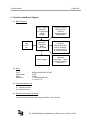
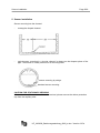
®
Badger Meter Europa GmbH
VHQ 500-SP/SPS
Ultrasonic flow meter
for open channels and partially filled
pipes
INSTALLATION MANUAL
Februar 2008 (Version 3.07a)
UF_VHQ500_Bedienungsanleitung_0802_e.doc
Contents
Page
1. General description ........................................................................................................... 1
2. Technical data/Switch diagram ........................................................................................ 2
2.1 Switch diagram ............................................................................................................. 2
2.2 Data .............................................................................................................................. 2
3. Flow chart........................................................................................................................... 3
4. Description of front panel ................................................................................................. 4
5. Installation and putting into operation ............................................................................ 5
6. Programming ..................................................................................................................... 6
6.1 Programming on stage „ON“......................................................................................... 6
6.2 Level adjustment......................................................................................................... 10
6.3 New Site ..................................................................................................................... 17
7. Switch on and measure................................................................................................... 24
8. Wiring terminals............................................................................................................... 26
9. Analogue board input/output .................................................................................... 27/28
10. CPU-board ........................................................................................................................ 29
General description
Page 1/29
1. General description
The flow meter VHQ 500-SP was designed for flow measurement in partially filled pipes
and open channels.
A sensor measures flow velocity and level.
A 32 bits microprocessor calculates and administrates the measuring data.
A LCD graphic display (128 x 64 pixels) allows data programming and data read out.
The programming is menu driven upon dialog texts and numbers are entered upon a
keypad.
A 4digit ID number prevents from unauthorized access and protect the parameters of the
measurement site.
The programming is showed in chapter 3 in the form of a flow chart and described in
chapter 6.
The flow meter has a 256 KB RAM memory, which records the measuring data. 256 KB
RAM corresponds to about 25.000 measuring data. The memory records following data:
Date, time, flow, flow velocity, level, quantity, measurement site.
A RS232 serial port makes data read out on PC possible.
The unit can administrate up to 99 measurement sites.
Three potentialfree contacts can be programmed to transmit either quantity pulses or limit
values.
For external level measurement (sensor) an analogue input 4 – 20 mA is available.
Analogue outputs 1 and 2 are isolated. Both can be programmed for 0-20 mA or 4-20 mA
and be alternatively assigned to level, flow or flow velocity.
Power supply for the portable meter is ensured by an integrated 12V battery. A battery
charger will be connected to the meter from outside to recharge the battery. The battery is
protected from low discharging and has a life time of about 7 days. Requested power
supply for the stationary meter is 90 to 240 VAC or 18 to 32 VDC.
UF_VHQ500_Bedienungsanleitung_0802_e.doc / Version 3.07a
Technical data
Page 2/29
2. Technical data/Block diagram
2.1 Block diagram
graphic display
resolution
64 x 128 pixels
serial
keypad
CPU
MC68332
512K flashRAM
512K RAM
serial
port
to PC
etc.
power supply
analogue outputs
2x0-20 mA or
4-20 mA
3x pulse outputs
potentialfree
analogue digital
converter
18 bits resolution
max. 4 channels
1 analogue input
4-20 mA isolated
ultrasonic
transmitter 1 Mhz.
ultrasonic receiver
evaluation
2.2 Data
CPU
Flash-RAM
RAM
Interfaces
:
:
:
:
Motorola MC68332 32 bits
512 K
512 K
1 x RS232 serial port
1 x serial TTL
2.3 Combined sensor V/H
a)
b)
Doppler velocity
pressure level
2.4 External sensor input 4-20 mA
for level measurement power supply 24 VDC / max. 300 mA
UF_VHQ500_Bedienungsanleitung_0802_e.doc / Version 3.07a
10
System
110
Authorization
Enter access code
1110
11110
Delete
11120
Output
calibration
Enter PIN
code.
Flow
velocity
11130
Calibration of analogue
outputs 1 and 2
System
reset
Adjustement of flow
velocity.
Return
Return
User
Low power
mode
11210
Display
Battery status
11220
Damping
factor
Level
11230
adjustement
A
Measuring
120
Start and stop of
measuring site and
data selsction.
Stored site
Low power mode
switch on/off of the
processor, analogue
outputs and FIFO.
Selection of Damping
factor for V and H.
adjustment
int. sensor
1210
12110
Numeric
Graphic
Current site
1230
Return
1220
12120
Level
121210
Flow
velocity
121220
Flow
121230
Return
12210
Angular
Rectangular
Display of current
measuring site by switch
on/off.
Trapezoid
Data transmission /
Simulation
Return
130
Simulation 1310
1320
Data
trasnmission
Enter simulation values
and simulation mode.
Switch on/off.
Data transmission from
flow meter to PC.
Return
12220
Round
Further shapes
Return
Return
121110
Paramet.
Return
Selection
int./ext. sensor
Enter site number and
name of the site.
A system reset will
be started.
ext. sensor
Return
New site
111120
Quantities will
be deleted.
12230
Circular
U-shape
New shape
Egg
shaped
Return
Paramet.
Return
Paramet.
Return
Paramet.
121110
121110
Display of site
parameters.
Display of site
parameters.
Display of site
parameters.
Page 3/29
Installation manual VHQ 500 SP/SPS z Version 3.07a
Return
111110
Totalizer reset
Flow chart
Language
selection,
Information if
displayed
date and time
are wrong
121110
Return
Enter channel dimensions, max. limit
values, offset values for V+H+Q, normal
and level depending memory intervals,
switch value for pulse output, rise factor
and corresponding entry point,
assignment of analogue and switch
outputs to V+H+Q and pulse output.
Display of site
parameters.
122110
Enter channel dimensions, max. limit values, offset values for
V+H+Q, normal and level depending memory intervals,
switch value for pulse output, rise factor and corresponding
entry point assignment of analogue and switch outputs to
v+H+Q and pulse output.
Enter channel dimensions, max. limit values, offset values for
V+H+Q, normal and level depending memory intervals,
switch value for pulse output, rise factor and corresponding
entry point, assignment of analogue and switch outputs to
V+H+Q and pulse output.
Enter channel dimensions, max. limit values, offset values
for V+H+Q, normal and level depending memory
intervals, switch value for pulse output, rise factor and
corresponding entry point, assignment of analogue and
switch outputs to V+H+Q and pulse output.
A
122120
A
122210
A
122220
A
Description of front panel
Page 4/29
4. Description of front panel
Badger Meter
VHQ 500-SP
Graphic display
7
8
9
128 x 64
4
5
6
1
2
3
*
0
E
pixels
Function keys
Keypad
ON/OFF
- Key on/off to switch on/off
- Function keys are used to retrieve measuring data and to program the unit.
- Keypad for programming.
UF_VHQ500_Bedienungsanleitung_0802_e.doc / Version 3.07a
Sensor installation
Page 5/29
5. Sensor installation
Sensor mounting into the channel:
-
rectangular shaped channel
-
typical sensor mounting in a circular channel is always on the deepest place of the
pipe. The sensor is usually screwed on a mounting band.
sensor mounting by sludge
standard sensor mounting
CAUTION FOR STATIONARY VERSION!
After connection of the sensor cable at the terminal, please remove the rubber protection
cap from the capillary tube.
UF_VHQ500_Bedienungsanleitung_0802_e.doc / Version 3.07a
Programming
Page 6/29
6. Programming
6.1 Programming on stage „ON“
Once the meter has been switched on, the operation software is loaded into the RAM.
Following screen appears on the display:
Illustration 10
Badger Meter
VHQ 500-SP
Version x.xx
Copyright 1998
After this indication, the display switches to the input of ID
number.
Illustration 10.1
Enter ID number.
The ID number is a factory adjusted 4-digit code.
If you lose this code, please call Badger Meter and give the
serial number f.i. 01.1999.001.
Illustration 11
Press key for your
language
Selection of language. Press the key accordingly.
DEUTSCH ENGLISH
UF_VHQ500_Bedienungsanleitung_0802_e.doc / Version 3.07a
Programming
Page 7/29
Illustration 12
Please check date and time.
Illustration 13
If date and time is correct, press CONTINUE.
If date and/or time is wrong, press NEW ADJUSTMENT.
Illustration 14
Adjust date and time with LEFT/RIGHT keys.
Enter the figures by pressing numbers on the keypad and
confirm with OK.
Illustration 15
System: Service,
reset totalizer,
delete datafile
Measure : stored and
new site date
Transmit data
Simulation:
SYSTEM
MEASURE
TRANSMIT/
SIMULA.
Choice of programming stage:
SYSTEM, MEASURE, TRANSMIT DATA
RETURN
or RETURN.
Select SYSTEM
Select MEASURE
Select TRANSMIT-SIMUL.
Select RETURN
Illustration 16
Illustration 36
Illustration 12
UF_VHQ500_Bedienungsanleitung_0802_e.doc / Version 3.07a
Programming
Page 8/29
Illustration 16
Authority : Service, calibration
User : Power-save-mode,
damping factor,
calibration level,
Display: Battery - cond
AUTHORITY
USER
Select USER
Select AUTHORITY
Select DISPLAY
Illustration 17
Illustration 25
Illustration 16.1
RETURN
DISPLAY
Illustration 16.1
Battery-voltage:
12.45V
Indication of the actual battery voltage.
If the battery voltage is below the minimum, this will appear
on the display.
Illustration 17
Power-Save-Mode (save battery power)
Damping factor
Level sensor calibration (ext./int.)
P o we r - S a v e - M o d e :
D am ping fa ctor:
C alibration lev el:
ext. int. level sensor
PO W ERS AV E - M
D A M PI N G FA C TO R
C AL IB R .
L E VE L
R E T U RN
Select POWER-SAVE-M
Select DAMPING FACTOR
Select CALIBR. LEVEL
Select RETURN
Illustration 18
Illustration 19
Illustration 20
Illustration 16
Illustration 18
Power-S.-M.
Ana.outputs:
FIFO:
OK
UP
>ON/OFF
ON/OFF
ON/OFF
DOWN
SELECT
Power-Save-Mode ON/OFF (if this mode is ON, the electronic
will go into sleep mode between the programmed measuring
intervals).
Analogue outputs ON/OFF (if no analogue output is
requested, select OFF to save power).
FIFO ON/OFF (ON means first in, first out)
(OFF means storing until memory filled)
Select ON/OFF with key SELECT and UP/DOWN.
Confirm with OK.
UF_VHQ500_Bedienungsanleitung_0802_e.doc / Version 3.07a
Programming
Page 9/29
Illustration 19
Damping factors
1 = 1 x measurement and indication
2 = 2 x measurements with average values
3 = 3 x measurements with average values
4 = 4 x measurements with average values
5 = 5 x measurements with average values
6.2 with
LevelLEFT/RIGHT.
adjustment
Select
Confirm with OK.
Damping factor
Level
:
5
Velocity
:
5
OK
L E FT
R IGH T
Illustration 19.1
Selection of the level sensors ext./int.
int. spanl. = standard V/H sensor, illustr. 20
ext. spanl = sensor with 4-20 mA output, illustr. 24.1
Return = illustr. 17
int. spanl.:
Calibrate int.
levelsensor
ext. spanl.:
Calibrate ext.
levelsensor
INT.
SPANL.
EXT.
SPANL.
RETURN
UF_VHQ500_Bedienungsanleitung_0802_e.doc / Version 3.07a
Programming
Page 10/29
6.2 Level adjustment
Illustration 20
Fill into
a tank the
min. level,
put in the sensor
and press OK - Key
OK
Adjustment of minimum level of the internal sensor, press OK.
RETURN
Illustration 21
Enter minimum level and confirm with OK.
Use LEFT/RIGHT keys and keypad.
UF_VHQ500_Bedienungsanleitung_0802_e.doc / Version 3.07a
Programming
Page 11/29
Illustration 22
Adjustment of maximum level of the int. sensor.
Confirm with OK.
Fill into
a tank the
max. level,
and press OK- Key
OK
RETURN
Illustration 23
Capturing maximum level.
Illustration 24
Enter maximum level and confirm with OK.
Use LEFT/RIGHT keys and keypad.
UF_VHQ500_Bedienungsanleitung_0802_e.doc / Version 3.07a
Programming
Page 12/29
Illustration 24.1
Connect the external
sensor with the current
input of the electronic.
OK
Adjustment of the external sensor.
RETURN
Illustration 24.2
4 mA from external sensor, confirm with OK.
For calibration
enter the min.
level.
0.000m
OK
LEFT
RIGHT
RETURN
Illustration 24.3
For calibration
enter the max.
level.
0.000m
OK
LEFT
RIGHT
20 mA from external sensor, confirm with OK.
RETURN
Illustration 25
Enter 4 digit ID-number (authorized persons only).
Use keypad and confirm with OK.
UF_VHQ500_Bedienungsanleitung_0802_e.doc / Version 3.07a
Programming
Page 13/29
Illustration 26
Delete totalizator, measuring data and system reset.
Calibration of analogue outputs.
Adjustment of flow velocity.
Delete: Totalizer - or
system - reset
Calibration :
analogue outputs
Adjustment actual
velocity
DELETE
CALIBR.
ANAL. OUT
ADJUST
VEL.
RETURN
Key DELETE
Key CALIBR. ANAL. OUT.
Key ADJUST. VEL.
Key RETURN
Illustration 27
Illustration 28
Illustration 33
Illustration 16
Illustration 27
Select RESET TOTALIZATOR and measuring data
Select SYSTEM RESET (all measuring data and stored
parameters are deleted).
Select RETURN to return to illustration 26
Illustration 28
Select calibration of analogue outputs 0-20 mA or 4-20 mA.
Key 0-20 mA
Illustration 29
Key 4-20 mA
Process like 0-20 mA
Key RETURN
Illustration 26
Illustration 29
Calibration of analogue output 1, connect current meter.
Adjust 0 mA with UP/DOWN keys.
Confirm with OK
Illustration 30
Key RETURN
Illustration 28
Adjustment,
from analogue output 1,
zero word:
Span : 20000
OK
UP
D OW N
R E TURN
UF_VHQ500_Bedienungsanleitung_0802_e.doc / Version 3.07a
Programming
Page 14/29
Illustration 30
Calibration of analogue output 1.
Adjust 20 mA with UP/DOWN keys.
Confirm with OK
Illustration 31
Key RETURN
Illustration 29
Illustration 31 is like illustration 29 but calibration analogue
output 2.
Illustration 32 is like illustration 30 but calibration analogue
output 2.
Illustration 33
Adjustment of flow velocity.
Enter actual velocity with LEFT/RIGHT buttons and keypad.
Confirm with OK
Illustration 34
Key RETURN
Illustration 26
Adjustment of
actual velocity
in m/s
0.000 m/s
Level : 0.200 m
OK
LEFT
RIGHT
RETURN
Illustration 34
Compensation of velocity is released by pressing OK.
After display „Please wait“, you go automatically back to
illustration 26.
Illustration 35
Key STORED SITE (already configurated) Illustration 36
Key NEW SITE
Illustration 46
Key ACTUAL SITE
Illustration 72
Key RETURN
Illustration 15
UF_VHQ500_Bedienungsanleitung_0802_e.doc / Version 3.07a
Programming
Page 15/29
Illustration 36
Select an already stored site by pressing OK.
On the next two pages
you can select for
the measuring points
a site number (1-99)
and a site description (max.8 digits)
Key RETURN
Illustration 35
RETURN
OK
Illustration 37
Select a stored site with UP/DOWN keys.
Confirm with OK.
Key RETURN
Illustration 35
Site :
00 channel
01
02
03
04
05
UP
OK
DOWN
RETURN
Illustration 38
Start or stop the measuring procedure by pressing SELECT.
Confirm with OK.
Illustration 39
Key RETURN
Illustration 37
Press SELECT key to
start or stop
the measurement
ON/OFF
SELECT
OK
RETURN
Illustration 39
Site
level
Velocity
Flow
Total
: 00 channel1
:
0.000 m
:
0.000 m/s
:
0.000 l/s
: 23.00000 m³
Qty since: 09.09.98 12:10
INT.SENSOR
12.000000 m3
REPORT
GRAPHIC
RETURN
Indication of measuring values incl. site #, total, display and
actual working sensor.
Key REPORT
Key GRAPHIC
Key RETURN
Illustration 40
Illustration 43
Illustration 38
UF_VHQ500_Bedienungsanleitung_0802_e.doc / Version 3.07a
Programming
Page 16/29
Illustration 40
Stored measuring data:
1. Position # 2. Date
5. Level
6. Flow
3. Time
7. Total
Key PARAMET.
Key UP/DOWN
Key RETURN
4. Flow velocity
5. Site #
Illustration 41
shift measuring values
Illustration 39
Illustration 41
SITE
:
00 channel1
MAIN- RECORDING -INT:
MAX. LEVEL .:
ALTERNATE-RECORDING INT:
Indication of adjusted parameters.
15 s
2.5000 M
001 MIN
0 M3
0.000 M
0 %/M
PULSE OUTPUT:
ENTRY POINT
RISE FACTOR
Key RETURN
Illustration 39
Select graphic LEVEL
Select graphic VELOCITY
Select graphic FLOW
Key RETURN
Illustration 43
Illustration 44
Illustration 45
Illustration 39
RETURN
Illustration 42
Select graphic :
View level
View velocity
View flow
VELOCITY
LEVEL
FLOW
RETURN
Illustration 43
Site:
00 channel1
LEVEL
Graphic of level with site #, offset of sensor and set point.
001MIN
MAX=
2.5000
M
SETP=
0.8000
M
Key PARAMET.
Key RETURN
OFFSET=
0.0080 M
PARAMET.
Illustration 41
Illustration 42
RETURN
UF_VHQ500_Bedienungsanleitung_0802_e.doc / Version 3.07a
Programming
Page 17/29
Illustration 44
SITE
00
VELOCITY .
Graphic of flow velocity with site #, offset of sensor and set
point.
channel1
001 MIN
MAX=
100,00
M/S
SETP=
50.000
M/S
OFFSET=
0.0080 M/S
PARAMET.
RETURN
Key PARAMET.
Key RETURN
Illustration 41
Illustration 42
Illustration 45
Site
00
Graphic of flow with site #, and set point.
channel1
FLOW
001 MIN
MAX=
1000
L/S
SEPT=
100,0
L/S
Key PARAMET.
Key RETURN
Illustration 41
Illustration 42
RETURN
PARAMET.
6.3 New site
Illustration 46
Indication of the shape of the latest selected site.
The actual
channel is:
01 KANAL1
0.600 m
Key OK
Key Return
Illustration 46.1
Illustration 35
Continue with OK
Back with RETURN
Illustration 47
Illustration 35
1.000 m
OK
RETURN
Illustration 46.1
On the next two pages
you can select for
the measuring points
a site number (1-99)
and a site description (max.8 digits)
OK
RETURN
UF_VHQ500_Bedienungsanleitung_0802_e.doc / Version 3.07a
Programming
Page 18/29
Illustration 47
Enter site # upon the keypad.
Continue with OK
Select with LEFT/RIGHT
Back with RETURN
Illustration 48
Illustration 35
Illustration 48
Site description
(max. 8 digits).
CHANNEL
ABCDEFGHIJKLMNOPQRST
UVWXYZ1234567890
OK
LEFT
RIGHT
Select letters or figures by moving the flashing line under the
digits with LEFT/RIGHT keys.
Store the site description with STORAGE.
Continue with OK
Illustration 49
STORAGE
Illustration 48.1
Selection of the measuring
range of the ext. and
int. sensor.
INT. above
EXT. above
OK
LEFT
0.000m
0.000m
R IG H T
R E T UR N
Example:
- Measuring only with internal sensor adjustement = 0.000m
- Measuring only with external sensor adjustement = 0.001 m
- Measurement with internal sensor up to 0.200 m and external
sensor up to 1.000 m
adjustment internal = 0.000 m
adjustment external = 0.200 m
- Measurement with external sensor up to 0.200 m and internal
sensor up to 1.000 m
adjustment internal = 0.200 m
adjustment external = 0.000 m
Illustration 49
Angular: rectangular -,
trapezoid
Round: circular -,
egg shape
Other: special shape
Selection of channel shape:
Key ANGULAR
Key ROUND
Key OTHER (special)
Key RETURN
Illustration 50
Illustration
Illustration
Illustration 46
UF_VHQ500_Bedienungsanleitung_0802_e.doc / Version 3.07a
Programming
Page 19/29
Illustration 50
Select RECTANGULAR channel
Select TRAPEZOIDAL channel
Key RETURN
Illustration 51
Illustration 64
Illustration 49
Enter channel dimensions.
Select with LEFT/RIGHT keys.
Enter figures upon the keypad.
Continue with OK
RETURN
Illustration 52
Illustration 50
Illustration 51
UF_VHQ500_Bedienungsanleitung_0802_e.doc / Version 3.07a
Programming
Page 20/29
Illustration 52
Enter max. values for V, H and Q (assignment of analogue
outputs).
Select with LEFT/RIGHT keys (or figures upon the keypad).
Continue with OK
Illustration 53
RETURN
Illustration 49
Input max. values of:
Level
Velocity
Flow
OK
:
:
:
2.500 m
1.000 m/s
10.000 l/s
RIGHT
LEFT
RETURN
Illustration 53
Enter alarm set points for V, H and Q.
Select with LEFT/RIGHT keys (or figures upon the keypad).
Continue with OK
Illustration 54
RETURN
Illustration 52
Input the set points
Level
Velocity
Flow
:
:
:
2.500 m
1.000 m/s
10.000 l/s
RIGHT
LEFT
OK
RETURN
Illustration 54
I np u t
Enter offset values for level and velocity.
Select with LEFT/RIGHT keys (or figures upon the keypad).
Select positive/negative with ALGEBRAIC SIGN.
Continue with OK.
Illustration 55
offsets
offset level :
+ 0 .0 0 0 m
offset velocity.:
+ 0. 0 0 0 m / s
L EF T
OK
RIG H T
A LG EB RA I
SIG N
Illustration 55
Assign analogue and pulse outputs to V, H and Q.
Select 0-20 mA, 4-20 mA, pulse output 1, pulse output 2.
Select between V, H, Q and pulse output with UP/DOWN.
Confirm with OK
Illustration 56.
Assign analogue
and pulse outputs
Level
Velocity
Flow
Pulse o.
OK
UP
:
:
:
:
D OW N
SELECT
UF_VHQ500_Bedienungsanleitung_0802_e.doc / Version 3.07a
Programming
Page 21/29
Illustration 56
Input on the next
page required
record .-time- interval.
possible values are
15, 30 and 45 s,
or 1 up 999 min.
Continue with OK
Back with RETURN
Illustration 57
Illustration 53
RETURN
OK
Illustration 57
Select the storage time interval:
15 sec., 30 sec., 45 sec.
1 minute up to 999 minutes.
Select with LEFT/RIGHT keys (or figures upon the keypad).
Select seconds or minutes with TIME UNIT.
Confirm with OK
Illustration 58
Illustration 58
If you want to select a
level dependent
recording interval,
then press LEVEL -DEP.key
LEVELCONTINUE DEP.
RETURN
Change the storage time interval at a determined level.
Possible intervals are 15, 30, 45 sec. or 1 to 999 minutes.
Continue with OK
Illustration 60
Save with LEVEL-DEP. Storage
Illustration 59
Back with RETURN
Illustration 56
Illustration 59
Select time and level with LEFT/RIGHT keys and enter time
and level upon the keypad.
Select seconds or minutes with TIME UNIT.
Confirm with OK.
Illustration 60
UF_VHQ500_Bedienungsanleitung_0802_e.doc / Version 3.07a
Programming
Page 22/29
Illustration 60
Configuration of the totalizer pulse output 1 to 999 litres or
0,001 to 999 m³.
Select with LEFT/RIGHT keys and keypad.
Select between litres and m³ with UNIT key.
Confirm with OK
Illustration 61
Illustration 61
Configuration of the entry point (start point) of rise factor.
Enter level with LEFT/RIGHT keys and keypad.
RETURN
Illustration 58
Confirm with OK
Illustration 62
Illustration 62
Configuration of the rise factor.
Enter rise factor in % per metre (max. 255%/m).
Select with LEFT/RIGHT keys and keypad.
Key RETURN
Illustration 61
Confirm with OK
Illustration 63
Illustration 63
Save all configured data by pressing OK.
Press OK for storage
Key RETURN
Illustration 37
Illustration 62
UF_VHQ500_Bedienungsanleitung_0802_e.doc / Version 3.07a
Programming
Page 23/29
Illustration 64
Enter trapezoidal channel dimensions.
Select with LEFT/RIGHT keys and keypad.
Key RETURN
Illustration 49
Illustration 65
Enter circular channel dimensions.
Select with LEFT/RIGHT keys and keypad.
Key RETURN
Illustration
Illustration 66
Enter egg shaped channel dimensions.
Select with LEFT/RIGHT keys and keypad.
Key RETURN
Illustration
UF_VHQ500_Bedienungsanleitung_0802_e.doc / Version 3.07a
Switch on and measure
Page 24/29
7. Switch on and measure
By configuring actual site „ON“ in chapter 6, page 14, illustration 35, you come directly
after having switched on the VHQ into the measuring mode. The latest channel you have
chosen appears on the display.
Switch on the meter.
Illustration 70
After this indication, the display switches to the input of ID-number.
Badger Meter
VHQ 500-SP
Version x.xx
Copyright 1998
Illustration 71
Enter ID number.
The ID number is a factory adjusted 4-digit code.
If you lose this code, please call Badger Meter and give the serial
number.
Illustration 72
Press SELECT key to choose ON/OFF (start or stop the measuring
mode).
Confirm with OK
Illustration 73
Press RETURN to
choose a new site
Illustration 74 resp. 37
UF_VHQ500_Bedienungsanleitung_0802_e.doc / Version 3.07a
Switch on and measure
Page 25/29
Illustration 73
Site
level
Velocity
Flow
Total
: 00 channel1
:
0.000 m
:
0.000 m/s
:
0.000 l/s
: 23.00000 m³
Qty since: 09.09.98
Int. sensor
REPORT
12:10
12.000000 m3
GRAPHIC
Indication of measuring values incl. site #, total, etc.
Key REPORT
Illustration 40
Key GRAPHIC
Illustration 43
Key RETURN
Illustration 72 or 38
RETURN
Illustration 74
Select a stored site with UP/DOWN keys.
Confirm with OK.
Key RETURN
Illustration 46
Site :
00 channel
01
02
03
04
05
OK
UP
DOWN
RETURN
UF_VHQ500_Bedienungsanleitung_0802_e.doc / Version 3.07a
Wiring terminals
Page 26/29
8. Wiring terminals
1
100-230VAC
50/60Hz
1
4
( Pink )
Transm. +
Transm. ( Gray )
1
5
6
Inner shield
3
( Green )
Inner shield
2
Receiver -
Attention !
Sensor cable outer shield
connected to cable gland
1
possible )
Power supply
(cable as short as
Velocity
Receiver + (Yellow )
4
+12V
- 5V
( Blue )
Shield (GND)
1
5
+ Level
2
( White)
6
Pressure level
( Red )
+5V
( Brown )
3
Shield (GND)
4
ANALOG - OUT 1 -
GND
ANALOG IN +
4
ANALOG IN -
1
2
ANALOG - OUT 2 -
3
2
ANALOG - OUT 2 +
Relay 2
3
1
Pulse out
4
2
3
1
4
2
3
Relay 1
Pulse outputs
- Use only shielded cables
- Outer shield connected to cable gland
+ 24V
1
ANALOG I/O
3
ANALOG - OUT 1 +
1
4
2
3
RXD
4
TXD
1
+ 5V
2
Serial
RS232
GND
UF_VHQ500_Bedienungsanleitung_0802_e.doc / Version 3.07a
Analogue board input/output
Page 27/29
9. Analogue board input/output
Jumper 1-3
Pulse output
Set point 2
Set point 1
Fuse
5x20mm
1.6AT s/0
b/0
connection analogue in/out (component side)
UF_VHQ500_Bedienungsanleitung_0802_e.doc / Version 3.07a
Analogue board input/output
Page 28/29
NO
NC
C
S. AG1
NO
NC
C
S: AG2 IMP:
1 2
3
4
analogue in
5 6 7
8
analogue out
AG
NO
NC
C
power supply 24VDC
230 VAC power supply
PE
N
L1
PE
GND
+24VDC
set point 1
set point 2
Pulse output
9 10 11 12
open collector
output
Jumper 1-3
connection analogue in/out (solder side)
1
2
3
4
5
6
7
8
9
10
11
12
+24VDC out
a. GND
a. input – 4-20mA
a. input + 4-20mA
a. output 2 –
a. output 2 +
a. output 1 –
a. output 1+
set point 1
set point 2
pulse output
GND
UF_VHQ500_Bedienungsanleitung_0802_e.doc / Version 3.07a
CPU-board
10.
Page 29/29
CPU board
Connection
CPU - board
+12V
power supply
at 12V DC
GND
+12V
-12V
GND
Receive +
Receive -
H-SENSOR
-Sens. white
+Sens. green
V-Doppler
Send +
Send –
Lithium
½ AA
Interface
RS232
connection analogue in/out
(solderside)
UF_VHQ500_Bedienungsanleitung_0802_e.doc / Version 3.07a
Hotline
Tel.
Fax
®
+49-7025-9208-0 or -79
+49-7025-9208-15
Badger Meter Europa GmbH
Subsidiary of Badger Meter, Inc.
Nürtinger Strasse 76
72639 Neuffen (Germany)
E-mail: [email protected]
www.badgermeter.de
UF_VHQ500_Bedienungsanleitung_0802_e.doc / Version 3.07a