
1
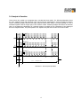
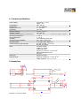
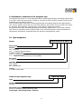
FMAX SERIES
Installation manual
Guided Magnetic Absolute Linear Encoder
FMAX-000-E-16-10
Doku Art. Nr. 799000042
1. INTRODUCTION
3
2. SAFETY
3
2.1 Fault clearance
3
3. PRINCIPAL OF FUNCTION
4
4. TECHNICAL SPECIFICATIONS
5
5. DIMENSIONS
5
6. INSTALLATION/FIRST START UP
6
6.1 Place of Installation
6
6.2 Installation of the guide carriage
6
6.3 Guide rail
6
6.3.1. Installation of the rail
6
7. TERMINAL ASSIGNMENT
6
8. INTERFACE
6
8.1 Teaching procedure / Offset
7
8.11 Teaching procedure:
7
8.12 Offset adjustment
7
9. RESISTANCE TO CHEMICALS OF THE MAGNETIC TAPE
8
10. TYPE DESIGNATION
8
11. LIABILITY EXCLUSION / GUARANTEE
9
2
1. Introduction
Series FMAX is an absolute magnetic length measuring system and only of use for recordation of lengths. It
consists of a guide carriage, where sensor technology and translator are placed, and a guide rail FSMAB. A
magnetic tape is installed on the guide rail. The guide carriage is contactless slided over the magnetic tape.
For interface a RS422 is available. Further interfaces are in preparation.
The absolute measuring system offers crucial advantages:
no reference adjustment necessary
direct measurement
measuring lengths up to 650 mm
high resolution up to 0,01 mm
repeating accuracy +/- 0,01 mm
protection against dirt and dust
easy installation
Typical applications are paper cutting machines, hydraulic presses, wood- and sheet metal processing machines.
2. Safety
Attention!
To ensure a perfect function of the FMAX-System the following installation guidelines must be strictly observed and followed. Otherwise the guarantee expires and
ELGO Electric GmbH takes no liability and guarantee for malfunctions or damages caused e.g. by incorrect installed wires or other external sources of error or
interference, which are exactly explained below. Please read the instructions carefully before putting the controller into operation..
As well ELGO Electric GmbH is not liable for possible machine- and/or personal
damages, which could arise through defective material on the measuring system
and the following circuit. The machine producer is obliged to take and to carry out
appropriate security relevant measures.
The type label, which can be found on the measuring system is of use for the precise identification of the
measuring system. It gives information regarding the precise type designation (see chapter 10. type designation on page 8), delivery date and production number. These details are always necessary, when contacting
ELGO Electric GmbH.
2.1 Fault clearance
Place of Installation
At least 0,5 m away from inductive and capacitive disturbance sources like contactor, relays, motors, switching power supply, clocked controller , etc. In principle lay the FMAX-cable separated from power wires and
keep distance to disturbance sources. For installation near other magnets, a minimum distance to the magnetic tape of 100 mm is necessary. If there occurs interferences in spite of applying all above mentioned
measures proceed as follows:
1.
2.
3.
4.
Add RC elements over contactor reels of AC contactors (for example 0,1 μF/100 Ω).
Add recovery diodes over DC inductances
Add RC elements over each engine phase (in connector box of the engine)
Install a power filter before the external power supply
3
3. Principal of function
Three sensors are guided over a magnetic tape, recorded with three tracks. The following illustration shows
the three magnetic tracks with following north- and south pole magnetization, sensed by magneto-resistive
resistor measuring bridges. Between the single magnetic tracks there always is an equal shifting ΔX. This is
evaluated together with the single signs of the resistive resistor measuring bridges and delivers an absolute
value. An unambiguous classification of a absolute position is possible by the combination of the phasing of
the three magnetic tracks. The phase position zero repeats every 650 mm for each of the three tracks.
Sensor 1
Track1
S N SN S N S N SN S N S N S N SN S N
SN SN SN
U1
Sensor 2
Track2
N SN SN SN SN SN SN SN SN SN SN
S
S N SN S N
U2
Sensor 3
Track3
N SN SN SN SN SN SN SN SN SN SN SN
S
SN SN SN
U3
0
0
L
X
ΔX
max.
= 650,00 mm
Illustration 1. functional principle FMAX
4
4. Technical specifications
Power supply:
Consumption:
Output level:
Repeating accuracy:
Resolution:
Output frequency:
Measuring length:
Accuracy of the system (in μm for 20°C):
Operating temperature:
Store temperature:
Humidity:
Operating height (altitude):
Protection class:
Sensor housing / guide carriage:
Wire:
Guide rail:
Magnetic tape:
10-30 VDC +/- 10 %
ripple < 5%
max. 150 mA
5 V TTL at RS422
+/- 0,01 mm
0,01 mm
500 Hz (2 msec)
max. 650 mm
+/- (40 + 20 x L) (L = Measuring Length im Meters)
0 - 50 °C
0 - 70 °C
non-condensing, 80% max.
max. 2000 m (sea level)
IP 54 (IP65 when Option V)
90 x 48 x 28 mm3 (L x B x H)
Die cast zinc (black)
tug chain suitable
length 30,0 m max.
weight: 58,0 g/m
approx.2 x 0,75 mm2, 6 x 0,14 mm2
radial flexibility 60 mm min.
wire exit
Aluminium Profile
expansion coefficient: α = 16 x 10-6 K-1
length expansion: ΔL = L x α x Δϑ
5. Dimensions
Illustration 1: Dimensions FMAX
5
6. Installation/first start up
6.1 Place of Installation
At least 0,5 m away from inductive and capacitive disturbance sources like contactor, relays, motors, switching power supply, clocked controller , etc. In principle lay the FMAX-cable separated from Power wires and
keep distance to disturbance sources. For installation near other magnets, a minimum distance to the magnetic tape of 100 mm is necessary.
6.2 Installation of the guide carriage
Take four M4-screws to fasten the guide carriage.
6.3 Guide rail
The guide rail contains a magnetic tape and a profile rail. Factory made the magnetic tape is stick together
with the profile rail.
6.3.1. Installation of the rail
Take four M4-screws to fasten the guide rail. For that, there are drill hole at the ends.
Attention:
For installation of guide carriage and guide rail pay attention to the markings on the magnetic
tape and on the sensor. A wrong installation will not deliver correct values.
7. Terminal assignment
RS232
RS422
signal cable
function
signal cable
function
white
brown
green
yellow
0V
+ 24 V
RX
TX
white
brown
gray
pink
green
yellow
0V
+ 24 V
TX TX
RX RX
8. Interface
The measuring system FMAX is provided with an interface in format RS422.
The data transfer has the following format:
9600 Baud
1 Start Bit
8 Daten Bits
1 Stop Bit
No Parity
Data record:
The actual value will be transferred every 2 msec. with following data record:
02h
xxh
xxh
xxh
xxh
xxh
xxh
03h
xxh
STX
ABS-Datas
ABS-Datas
ABS-Datas
ABS-Datas
ABS-Datas
ABS-Datas
ETX
BCC
The “Block check sum” is an „exclusive OR” of all datas
inclusive STX and ETX.
All values will be transferred in ADCII-format.
6
8.1 Teaching procedure / Offset
Should the desired display value differ from the factory-made adjusted original offset, a settlement can be
carried out by the external counting unit. Alternatively the offset can be changed by the RS-422 interface of
the FMAX (see point 8.11 and 8.12).
8.11 Teaching procedure:
Indication:
On delivery guide carriage and guide rail are numbered and belong together in pairs.
A teaching procedure is necessary, if only the guide rail or the guide carriage has to be replaced.
A teaching procedure has to be carried out as follows:
1. Guide carriage and guide rail are installed and the measuring system can stand at any place.
2. Afterwards the following record has to be sent to the measuring system:
02h STX
4ch „L“ = teaching procedure is started
03h ETX
4dh „M“ = BCC
3. The guide carriage has to be moved 30 mm in one direction with a speed of 0,01 m/s max. (10
mm/sec. max.) and following back again.
4. Afterwards the following record has to be sent to the measuring system:
02h STX
42h „B“ = teaching procedure is finished
03h ETX
43h „C“ = BCC
The teaching procedure is completed.
8.12 Offset adjustment
After installation and connection of guide carriage and guide rail a value will be transferred over the interface. As this value does not agree with the machine offset, an offset can be deposited usually at the controller side or directly at the measuring system. In order to adjust this offset at the measuring system, the Sensor has to be moved to the machine offset.
Afterwards the following record has to be sent:
02h STX
4eh „N“ = adjust zero point
03h ETX
4fh „O“ = BCC
The measuring system is adjusted to offset. All transmitted values are now related from this offset.
Attention:
This offset adjustment needs to be carried out at any change of guide carriage or guide
rail. In case the counting direction cannot be changed in the controller, the complete
slide-system has to be turned over.
7
9. Resistance to chemicals of the magnetic tape
The magnetic tape shows no or only small effects when contacting permanently the following materials after
2 to 5 years: formic acid, glycerol 93°C, linseed oil, soy beans oil, cotton seed oil, N-hexane, lactic acid, formaldehyde 40%, isooctane, petroleum.
Poor to medium effects result when contacting permanently the following materials after approximately 1
year: acetone, gasoline, acetic acid 30%, olein acid, acetylene, steam, acetic acid, pure acetic acid, sea water, ammonia, acetic acid 20%, isopropyl ether, stearic acid 70°C anhydrous, kerosene.
Strong effects result when contacting permanently the following materials after 1 to 5 months: benzene,
nitric acid 70%, turpentine, toluene, lacquer solvent, nitric acid red and vitriolic, carbon tetrachloride, trichloroethane, nitrobenzene, hydrochloric acid 37% and 93°C, tetrahydrofuran, xylene.
10. Type designation
Sensor
FMAX-XXX-XX.X-X-XXX-X
Series/Type
Version
000 = Standard
001 = 1. customer specified Version
Length of signal wire
03.0 = 3,0 m (Standard)
Lengths of 1,0/3,0/5,0/8,0/10,0 m are available
Resolution
2 = 0,01 mm
Interface
422 = RS422
232 = RS232
SSI = SSI Interface
Options
V = casted Version IP65
Guide rail with magnetic tape
FSMAB-000-0650
Type
Version
Standard
Measuring Length
650 mm = maximum possible measuring length
Total length = Measuring length + 150 mm
8
11. Liability exclusion / Guarantee
We have checked the contents of this instruction manual carefully, to the best of our knowledge and belief for conformity
with the described hardware and software. Nevertheless errors, mistakes or deviations can not be excluded, therefore we
do not guarantee complete conformity. Necessary corrections will be included in the subsequent editions. We appreciate
your ideas and improvement suggestions very much. Reprint, duplication and translation, even in extracts, are only allowed with a written authorization by the company ELGO Electric GmbH. We constantly strive for improving our products,
therefore we keep all rights reserved for any technical modifications without any notice.
ELGO Electric does not assume any liability for possible errors or mistakes.
The guarantee period is one calendar year from the date of delivery and includes the delivered unit with all components.
ELGO Electric GmbH will at its option replace or repair without charge defects at the unit or the included parts, verifiable
caused by faulty manufacturing and/or material in spite of proper handling and compliance to the instruction manual.
Damages verifiably not caused by ELGO Electric GmbH and due to improper handling are excluded from any guarantee
e.g. by applying faulty voltage, diffusion of liquid into the interior of the engine, using force, scratching the surface,
chemical influences etc.!
Subject to modifications ©ELGO Electric GmbH 2010
9


![El WE]](http://vs1.manualzilla.com/store/data/005973526_1-5126190d8f2880fb7d5b7ddc41b9f31a-150x150.png)