1
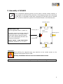
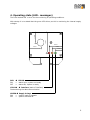
Installation manual
Magnetic Absolute Linear Encoder
positioning solution for elevator cabs
Resolution 1 mm
Up to 4 mm mounting distance to the magnetic tape
Absolute measuring distance up to 260 meter
Available as guided or unguided version
No calibration or reference run necessary
Direct measurement and installation at the elevator cabin
No yo-yo effect
Resistant against dirt (IP50 Standard)
Easy to install
Different interfaces available
Power supply: 10... 30 VDC
The magnetic tape can be hung vertically, spring loaded or mounted with a weight
• Wear free, touchless and low noise measurement principle
•
•
•
•
•
•
•
•
•
•
•
•
LIMAX2-000-E_36-06.doc
Dok-Nr. 799000254
1. General
3
2. Safety instructions
4
2.1 Fault clearance
4
3. Assembly of LIMAX2
5
4. Operating state (LED - messages)
6
5. Dimensions
7
6. Interfaces and Protocols
8
6.1 CANopen - Interface (on demand)
8
6.2 SSI - Interface (standard)
9
6.3 RS-232 / RS-422 Interface (option)
6.3.1 RS-422 (version 1.4) ADRESSABLE (option A22)
10
10
7. Mounting possibilities
13
8. Oscillation Damper
14
9. Technical Specifications
15
10. Magnetic tape AB20-XX
16
10.1 Tape-construction “R – D” two components tape
16
10.2 Tape-construction “A” two components tape
17
10.3 Resistance against chemical influences
18
10.4 Technical specifications – magnetic tape
18
10.5 Sticking and cutting
19
11. Type designation LIMAX2
11.1 Type designation of magnetic tape (Accessories)
12. Liability exclusion / Guarantee
20
21
22
2
1. General
bases on the already successfully in elevator applications used LIMAX Absolute
Linear Encoder and it is possible to use the sensor with a mounting distance from 0,1mm up to
4,0mm to the magnetic tape with a resolution of 1mm (other resolutions on demand). The
system is available as guided or unguided.
As a result of an increased possible mounting distance of up to 4 mm a further advantage
arises in the case of the guided version: During the measuring movement a substantially
smaller noise of magnetic tape in combination with the guide plate develops.
With the
measuring lengths up to 260 meters can be processed. The measured
„absolute” data (position) are transmitted to a super ordinate system (e.g. Control, SPS or PC)
via Interface. There they can be processed then.
The absolute linear encoder offers some crucial advantages:
•
•
•
•
•
•
•
•
•
•
•
no referencing necessary
no data leakage after power failure
space saving unit and simply installation
direct measurement
accurate positioning (no yo-yo effect)
measuring distance up to 260m
1mm standard resolution (others on demand)
operating speed up to 16 m/s
Wear free, touchless and low noise measurement principle
very resistant against dirt
magnetic tape guiding plate from sliding special plastic
The system can be assembled horizontally or vertically
In the guided standard version the guiding plate guarantees the correct distance between the
sensor and the magnetic tape. While with the unguided version of the LIMAX2 (option U) the
correct mounting distance (0,1... 4,0 mm) – along the whole measuring section – must be ensured by the installation.
For the mounting various accessories are available which simplifies the installation, they also
complement meaningful the linear encoder.
3
2. Safety instructions
Please note: Before first start up, read this installation manual carefully and
observe absolutely the installation instructions. The measuring system is only
dedicated for length measurements. The type label is intended for exact
identification of the measuring system and is situated on the sensor housing. It
informs about the exact type designation, the delivery date and the production
number. When contacting the company ELGO Electric GmbH please use these terms.
Attention! ELGO Electric GmbH is not liable for possible damages to machines or
to persons, which can result from defective material at the measuring system and
the connected units. The machine manufacturer is responsible for taking and
realizing the necessary safety precautions.
2.1 Fault clearance
The shielding of the signal cable should be connected only on one side with the
further connected unit (e.g. PC or PLC). The signal output cable must principally
be wired separately from heavy duty current wires and keep a distance of at least
0.5 m to inductive and capacitive interference sources as contactors, relays, engines, switch power packs, clocked controllers, etc.
If there arise interferences in spite of observing all above described points,
proceed as follows:
Add RC elements over contactor reels of AC contactors (e.g. 0.1 µF / 100 Ω).
Add recovery diodes over DC inductances.
Add RC elements over each engine phase and over the engine brake
(in the terminal box of the engine).
Do not connect PE (potential earth) to GND (Ground)
Connect a system filter at the external power supply
4
3. Assembly of LIMAX2
Three integrated Assembly-grooves at the sensor housing makes possible, a
very simple and self-describing assembly. M6 hexagonal screw-nuts (according
to DIN 933) or M6 square screw-nuts (according to DIN 562) can be inserted
here, in order to fasten the system from the desired side to the desired place.
Assembly-groove
Active sensor area
(at the unguided Sensor / option U):
The active sensor area at the scanning
side determines in the middle of the
sensor and reaches along the whole
case. When assembling therefore the
following rule applies:
Scanning side Æ
Active
Sensor area
Assembly-groove
magnetic tape
Sensor center = mag. tape center
(assembly tolerance = +/– 1 mm)
Assembly-groove
Attention!
When sticking the magnetic tape, pay attention to the marker arrows on the
magnetic tape and the sensor head.
A faulty installation delivers incorrect measurement values!
The marker arrows at senor and tape point to the positive counting direction!
5
4. Operating state (LED - messages)
The front located LED´s serve for the monitoring of operating conditions.
33,40mm
17,20mm
With startup it is to attend that the green LED shines, as this is monitoring the internal supply
voltages.
22,00mm
19,00mm
16,80mm
11,60mm
RED
ON
OFF
Æ ERROR
= status error, system not ready
= status OK, system is ready
YELLOW Æ Interface (state of interface)
Flashes during the data communication
GREEN Æ Supply Voltage
ON
= system ready to operate
OFF
= system switched off
6
5. Dimensions
Rear Cover
Topview
55mm
236mm
Attention! The grey parts of
the drawing and the grey
dimensions apply to the
guided version (standard) of
the LIMAX2.
244mm
40mm
51mm
55mm
Front Cover
40mm
51mm
55mm
7
6. Interfaces and Protocols
6.1 CANopen - Interface (on demand)
The measuring system is equipped optionally with an CAN interface after CANopen standard. The
following Identifier is given:
Bit rate 250 KB/s
CAN - Identifier
(6 Byte telegram)
1A3 (16) = Identifier
First 4 Bytes = position in mm (resolution 1 mm),
Next 2 Bytes = speed in mm/s
Because the system resolution is only 1mm and a average value formation is made, the smallest
speed increment is 14 hexadecimal. With this increments the measured speed increases.
Data protocol
LSB
xxh
xxh
xxh
MSB
xxh
ABS-Position
LSB
yyh
MSB
yyh
Speed
Connections:
Open wires (standard)
color
white
brown
orange
yellow
shield*
function
0 V / GND
+ 24 VDC
CAN low
CAN high
PE
9 poliger D-SUB Stecker
(options DM oder DF)
Pin Nr.
function
Pin 6
0 V / GND
Pin 9
+ 24 VDC
Pin 2
CAN low
Pin 7
CAN high
shield*
PE
*) please connect the shield only at the machine side!
8
6.2 SSI - Interface (standard)
Principle of the function: If the clock is not interrupted for the time Tm-T/2 (output of further 25 periods), the shift register clocks once again the same data value (error recognition in
the evaluation). Some encoders contain a Power Failure Bit (PFB). Attention: With the
LIMAX2 the PFB is alwas “LOW”!
Data protocol: readout the data (with 25 clocks)
T
SSI - Takt
23
22
21
20
19
18
17
16
15
14
13
12
11
10
9
8
7
6
5
4
3
2
24 Datenbits/ 3Bytes
1
0
PFB
PFB = Power Failure Bit
T = Periodendauer des Taktsignals
Tm = Monoflopzeit > 10µs
Connections:
Open wires
(standard)
color
white
brown
violet
grey
yellow
green
shield*
D-SUB
9 pin.
Pin Nr.
1
2
3
4
5
6
7
8
9
NEWLIFT
FST1 (D9M0)
function
Data +
Clock 24 VDC
0V / GND
Data Clock +
PE
function
0 V / GND
+ 24 VDC
Data Data +
Clock Clock +
PE
NEWLIFT
FST2 (D9M1)
function
0V / GND
Clock +
0V / GND
Data +
0V / GND
+ 24 VDC
Clock Data VCC
Masora
Delta (D9M2)
function
VCC
Data +
Data Clock +
Clock 0V / GND
*) please connect the shield only at the machine side!
9
6.3 RS-232 / RS-422 Interface (option)
If the measuring system is equipped with an RS232 or RS422 interface, the data communication has the following format:
9600 bauds
1 Start bit
8 data bits
1 stop bit
no parity
Data protocol: The measured absolute position will be represented with a resolution of 1mm
in the three ABS-position data bytes.
Version 2321 / 4221
STX
02h
MSB
xxh
xxh
LSB
xxh
MSB
yyh
ABS-position
LSB
yyh
ETX
03h
00h
0Dh
speed
Version 2320 / 4220
STX
02h
MSB
xxh
xxh
LSB
xxh
ETX
03h
00h
0Dh
STX = starts a message
ETX = ends a message
ABS-position
Connections:
Open wires
(standard)
color
white
brown
violet
grey
yellow
green
shield*
RS232
0 V / GND
+ 24 VDC
TX
RX
PE
RS422
0 V / GND
+ 24 VDC
TX TX
RX RX
PE
*) please connect the shield only at the machine side!
6.3.1 RS-422 (version 1.4) ADRESSABLE (option A22)
Principle format of a message:
to LIMAX2
STX
02h
Byte
1
answer
Byte
2
Byte
check
ETX
03h
STX
02h
Byte
1
Byte
2
Byte
3
Btye
4
STX = starts a message
ETX = ends a message
Check Byte = contains the arithmetic checksum of STX, byte1 and byte2
10
Position request of a LIMAX2 with the address „i“:
to LIMAX2
STX
02h
answer
04h
i
Byte
check
ETX
03h
STX
02h
MSB
xxh
xxh
04h = characterizes a message as position-request
i
= address of the requested LIMAX2 (0Bh – 7Fh)
Bit 0 has the value 10µm, position-values are always lower than FFFF00h
LSB
xxh
Adr.
i
ABS-position
A LIMAX2 address request:
Attach in each case only one LIMAX2 e.g. over a RS422/RS232 converter to the serial interface (COM-port)
of a PC.
to LIMAX2
STX
02h
answer
05h
05h
Byte
check
ETX
03h
STX
02h
FFh
FFh
i
xxh
ETX
03h
05h = characterizes a message as address request
i
= LIMAX2 address
FFh FFh does not occur immediately after STX with position inquiries as answer!
In this case i(0Bh <= i <= 7Fh) is the answer of the address request.
Allocation of a LIMAX2 address:
Attach in each case only one LIMAX2 e.g. over a RS422/RS232 converter to the serial interface (COM-port)
of a PC.
to LIMAX2
STX
02h
answer
06h
i
Byte
check
ETX
03h
STX
02h
FFh
FFh
i+
80h
ETX
03h
06h = characterizes a message as address allocation
i
= the new LIMAX2 address. Important: At the answer you get the new address + 80h.
The addresses 80h – FFh as well as 00h – 0Ah are FORBIDDEN. If you try to assign a address
smaller than eight, LIMAX2 gives you a negative answer and keeps its former address.
Important: Before you send a new message to the LIMAX2, wait for the answer first. After
allocating a new address, the LIMAX2 answers in max. 0,5s and in a few milliseconds in other
cases. After this time it is not expected to get an answer (transmission error).
Negative Answer:
If one of the described operations failed for some reason, LIMAX2 gives a negative answer with
an concerning error – code.
from LIMAX2
STX
02h
FFh
FFh
ERR
xxh
ETX
03h
ERR = Error-Code (04h – 0Ah) error – codes are listed at the next page
11
Error – Code meanings of an addressable LIMAX2:
Code
Meaning
04h
Wrong succession of bytes sent to LIMAX2, for example if 4. Byte after STX is no ETX or
the Byte after STX is not 0x04, 0x05 or 0x06.
05h
Receive Error: Error concerning the interface (for example if there has been sent a message with a wrong baud rate etc.)
06h
Invalid LIMAX2 address: appears after trying to assign an address smaller 0Bh or bigger
7Fh to LIMAX2.
07h
LIMAX2 has forgotten its address: check of internal redundant stored address of LIMAX2
is failed. This message is sent at power up immediately if an error in reading EEPROM is
detected or if the internal redundant stored address is not fit.
08h
Internal EEPROM storage error.
09h
Error in calculating the position (no tape, tape damaged or to big distance)
0Ah
Check-Sum-Error: Check-sum of a message sent to LIMAX2 is wrong.
Connection to a RS422 Master:
RS422-Master
LIMAX2-RS422 #1
LIMAX2-RS422 #n
12
7. Mounting possibilities
The magnetic tape can be installed guided or unguided:
Guided - hung vertically
For a free-hanging assembly in the elevator shaft the guided sensor variant (standard) is used. For this a magnetic tape in
construction R (standard) is hung up, parallel to the cabin, at the shaft ceiling and
provided at the lower side with a weight for
stabilization. Possibly lateral deviations
along the measuring distance can be compensated by a guide plate with optional
balance guidance’s at the bottom side of
the sensor housing. The sensor passes the
magnetic tape nearly contact free and in
the correct mounting distance. In order to
prevent an oscillating motion of the stabilization weight, a oscillation-damper should
be attached above the weight.
Unguided – Installation on a steel girder
In the case of a mounting directly at a
steel girder the unguided variant (U) is
used, which differs only by the renouncement of the guide plate from the
standard system. Here the sensor is
fastened to the cab and passes the
magnetic tape really contact free (preferably a tape in construction A). However it must be ensured with this version that the allowed mounting distance
is not exceeded along the whole measuring distance. Owing to the own magnetization, the tape can be fastened
without any mounting parts or sticky
tape, directly at the steel girder.
13
8. Oscillation Damper
If the magnetic tape should be assembled free-hanging, it recommends to stretch this at the
lower surface with a weight from 5 kg. In order to avoid, that there oscillations develop and
the magnetic tape together with the weight begins to oscillate there have to be a oscillation
damper above the weight. The following picture demonstrates the mounting of such an application.
Oscillation Damper
Magnetic tape
Weight for stabilization
(5 Kg)
14
9. Technical Specifications
Linear encoder
Power supply voltage
Current consumption
Signal levels
Repeat accuracy
resolution
Operating speed
Measuring length
10... 30 VDC
max. 0,2 A
According to the interface specification
+/- 1 Increment
1 mm (standard), others on demand
max. 16 m/s
max. 260 m
gap sensor / tape max. 4,0 mm (on demand larger distances – up to 10 mm are possible.
Therefore other tape pole lengths and a bigger housing design is necessary.)
Working temperatur
0... + 60° C
Operating temperatur - 20... + 70° C
Stock temperatur - 40... + 85° C
Humidity Not condensing, max. 80 %
Operating height max. 2000 m above sea level
Protection class
IP 50: standard version
IP 67: option V (sealed)
Sensor
Housing Aluminium (Al/Mg/Si 0,5)
Dimensions See dimension drawing
Cable
Cable length Depends on bit rate and equipped interface
min. bending radius 60 mm
15
10. Magnetic tape AB20-XX
Coding and data of the magnetic tape (one track system):
Basic data:
Width of the magnetic tape = 10 mm
Thickness of the magnetic tape ca. 1,5 mm
10.1 Tape-construction “R – D” two components tape
In the standard case the magnetic tape is delivered as described here. The assembly takes
place here via gluing on the respective mounting surface, it can also be assembled freehanging in the elevator shaft.
A
Scanning side
Magnetized plastic tape
(magnetic tape)
B
Magnetic leading steel band
(Conclusion volume)
Thickness: A + B = 1,5mm
Available lengths: See technical specifications
The magnetic tape consists of 2 components:
A
The magnetized, highly flexible plastic tape, connected on the lower side with:
B
Magnetic conductable and flexible stainless steel tape. It protects the plastic tape from mechanical damages and is a magnetic short circuit at the same time. This increases significantly the functional security under extreme magnetic influences. Both parts A and B are already factory-bonded (by ELGO). Alternatively the single components can be ordered separately (see type designation).
16
10.2 Tape-construction “A” two components tape
Assembly at a steel girder, by the own magnetic attraction or by gluing: This deviating variant is delivered without the magnetic conductive steel band. Therefore the tape
must be installed on a magnetic conductive surface, in order to increase the magnetic field
strength. The magnetic tape can be stuck together here or alternatively fastened by its
own magnetization e.g. on a steel girder.
C
Cover band for protection
(unnecessary for measurement)
Scanning side
A
Magnetized plastic band
(magnetic tape)
Mounting surface (e.g. steel girder)
Thickness A + C = ca. 1,5 mm.
Available lengths: See technical specifications
These deviant version (see the type designation) consists of 2 components:
A
The magnetized, highly flexible plastic tape.
C
To keep the flexibility for transport and installation the second part, a stainless, magnetic
permeable steel tape is delivered separately. It serves for mechanical protection of the plastic tape, is already equipped with a sticky tape and must be bonded on the magnetic plastic
tape after installation.
Storage reference, please note: In order to avoid tensions in the magnetic tape, it should be stored in stretched
or rolled up conditions – with the magnetized plastic tape
resp. scanning side outwards (see picture).
17
10.3 Resistance against chemical influences
Chemicals, showing no or only small effects:
Formic acid
Iso-octane
Mineral oil
Glycerol 93°C
Cotton seed oil
Formaldehyde 40%
Soy beans oil
N-hexane
Linseed oil
Lactic acid
Acetic acid 30%
Steam
Ammonia
Olein acid
Acetic acid
Acetic acid 20%
Chemicals, showing small to medium effects:
Acetone
Kerosene
Pure Acetic acid
Isopropyl ether
Gasoline
Acetylene
Sea water
Stearic acid 70°C anhydrous
Chemicals, showing strong effects:
Benzene
Xylene
Nitric acid
Nitric acid (red, vitriolic)
Turpentine
Hydrochloric acid
Lacquer solvent
Toluene
Tetrahydrofuran
Tetrachloride Carbon
Trichloroethylene
Nitrobenzene
37%, 93°C
10.4 Technical specifications – magnetic tape
Working temperatur range
0° … + 70°C
Operating temperatur range - 20° … + 85°C
Stock temperatur range - 40° … + 85° C
Operating height max. 2000 m above sea level
Humidity max 80 % (not condensing)
∆L = L x α x ∆ϑ (L = Messlänge in Meter)
Relative linear extension ∆L (∆ϑ = relative change of temperatur in °K
based on 20°C room temperatur)
Coefficient of extension α
Bending radius
Protection class
Available Width
Thickness
max. possible length
Pole length
Number of absolute tracks
16 x 10 –6 1/K
minimal 150 mm
IP67
10 mm +/- 0,2 mm
1,5 mm +/- 0,1 mm (Construction R-D)
1,5 mm +/- 0,1 mm (Construction A)
Up to 600 m as roll ware (longer on demand)
8 mm
1
18
10.5 Sticking and cutting
Attention!
When sticking the magnetic tape, pay attention to the marker arrows on the
magnetic tape and on the sensor head. A faulty installation delivers incorrect values. An already stuck magnetic tape is ruined after removing and can't be used
again. Observe also the counting direction of the measuring system.
The sticking procedure:
Preferably the magnetic tape should be stuck into a nut or aligned to an edge.
Tape construction R - D (standard):
1. The magnetic tape is already factory bonded with the conclusion tape. On the carrier
side (= conclusion tape) already the necessary sticky tape is fixed or is attached separately.
2. Now the magnetic tape is adjusted and glued on then. Most simply it is to be stick on
the magnetic tape in two steps. At first remove the adhesive film up to the half length
and stick it. Then stick the rest length.
3. Afterwards the cover band must be bounded with the separately sticky tape (if not already attached). It doesn’t matter on which side of the cover band the sticky tape is
fixed. The cover band must be stuck then on the magnetized plastic tape (magnetic
tape). The cover band serves for the protection of the magnetic tape. If a mechanical
damage of the magnetized plastic tape can be excluded, the installation can be done
without cover band (see Type designation Æ Options).
Tape construction A: In case of a vertical installation (e.g. on a steel girder), no sticking is
necessary, due to the fact that the magnetic rubber tape can be fastened by its own magnetization. The steel girder quasi replaces the conclusion tape. The cover band must be fastened
as described under 3. (see above).
Processing hint for the sticking of magnetic tapes
Materials to stick: The provided sticky tapes stick well on clean, dry and plain surfaces. Typical solvent for cleaning surfaces are a 50/50 mixed isopropyl-alcohol / water mixture or heptane. (Important: Please observe carefully the caution hints of the producer when using the
solvent.) The surfaces of materials as copper, brass etc. should be sealed to avoid an oxidation.
Proof: The stability of the adhesion is directly depending on the contact, which the adhesive
develops to the surfaces stuck together. A high proof results in a good surface contact. Sticking temperature: The optimal sticking temperature is between + 21°C and 38°C. Avoid colder
sticking surfaces than + 10°C, because in this case the adhesive becomes to hard and perhaps
a sufficient immediate adhesion is hardly to achieve. After proper sticking the stability of the
connection is ensured also when the temperature is below zero. The final tackiness of a sticking
is from experience reached after approximately 72 hours (at + 21°C).
19
11. Type designation LIMAX2
LIMAX2 - 00 - 030 - 1000 - XXXX - XXXXXX
Type
Absolute encoder for elevator tasks
Version
00 = Standard
01 = 1. special version
Signal cable in XXX Decimeter
030 = 3,0 m Æ Standard Length
(others on request)
Resolution in µm
1000 = 1000 µm bzw. 1 mm
0500 = 500 µm
0250 = 250 µm
0125 = 125 µm
Interface
CAO0 = Standard CANopen (on demand)
4220 = RS-422 (optional)
2320 = RS-232 Protocol ELGO (optional)
2321 = RS-232 Protocol ELGO Position & Speed (optional)
SSB0 = SSI-Interface (25 Bit Binary code)
SSG0 = SSI-Interface (25 Bit Gray code)
Options
(multiple nominations possible)
D9M0
D9M1
D9M2
D9F0
U
V
=
=
=
=
=
=
9 pin. D-SUB-Connector (Option NEWLIFT FST1)
9 pin. D-SUB-Connector (Option NEWLIFT FST2)
9 pin. D-SUB-Connector (Option Masora Delta)
9 pin. D-SUB-Jack (instead of open wires)
unguided: Without magnetic-tape-guiding-plate on the Sensor bottom side
Sensor housing in sealed IP67 version
Ordering example : 1 LIMAX2 in standard version with 3,0 m cable und Canopen-Interface,
9 pin. D-SUB-Connector (incl. counterpart) unguided (without magnetic-tape-guiding- plate),
Sensor housing in IP67 version: LIMAX2 - 00 - 030 - 1000 – CAO0 – D9M0 U V
20
11.1 Type designation of magnetic tape (Accessories)
AB20 -
80 -
10 -
1-
X-
D* -
15
Designation
AB20 = Absolute coded magnetic tape
Pole division
Basic pole division in 100µm Resolution:
80 = 4mm Pole division
Tape width
Tape width in mm:
10 = 10mm
Number of tracks
Number of magnetic tracks:
1 = Single track system
Tape construction
R = Standard: Magnetic tape bonded on permeable steel tape
(As unguided version at horizontal operating)
A = Magnetic tape on cover band (without further accessories)
Options
If no options are needed, ask this decade in the order to omit .
D = Without sticky tape and cover band (free hanging assembly in the shaft)
Number of bits
Bit number of the absolute code:
15 = 15 Bit - Code
Please indicate the desired length up to 1000 meters (001= 1m up to 000 = 1000 m)
Magnetic tape length = Measuring distance + 0,25 m
Further accessories – Pole foil (Article Nr. 511000220):
Determination of pole length resp. number of tracks on already installed tapes:
Further accessories: A special pole foil (app. 4 cm x 4 cm) is
available as and is useful to make the tape magnetization visible.
The pole length or the number of absolute tracks can be determined, in order to replace an already installed or unknown tape
correctly.
Single-lane coded magnetic tape
21
12. Liability exclusion / Guarantee
We have checked the contents of this instruction manual carefully, to the best of our knowledge and belief for conformity with the described hardware and software. Nevertheless errors,
mistakes or deviations can not be excluded, therefore we do not guarantee complete conformity. Necessary corrections will be included in the subsequent editions. We appreciate your
ideas and improvement suggestions very much.
Reprint, duplication and translation, even in extracts, are only allowed with a written authorization by the company ELGO Electric GmbH.
We constantly strive for improving our products, therefore we keep all rights reserved for any
technical modifications without any notice. ELGO Electric does not assume any liability for possible errors or mistakes.
The guarantee period is one calendar year from the date of delivery and includes the delivered
unit with all components. ELGO Electric GmbH will at its option replace or repair without charge
defects at the unit or the included parts, verifiable caused by faulty manufacturing and/or material in spite of proper handling and compliance to the instruction manual.
Damages verifiably not caused by ELGO Electric GmbH and due to improper handling are excluded from any guarantee e.g. by applying faulty voltage, diffusion of liquid into the interior of
the engine, using force, scratching the surface, chemical influences etc.!
Subject to change © ELGO Electric GmbH 2006
22