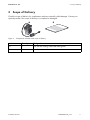
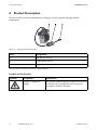
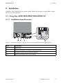
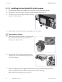
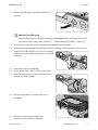
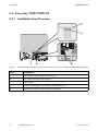
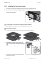
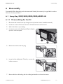
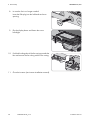
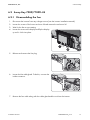
1
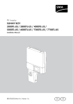
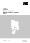
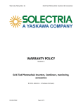
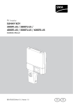
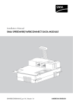
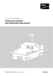
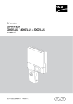
Accessories for SMA Inverters
Fan Retrofit Kit FANKIT02-10
Installation Manual
FANKIT02-IA-US_en-12 | Version 1.2
CA
US
SMA America, LLC
Legal Restrictions
Legal Restrictions
Copyright © 2014 SMA America, LLC. All rights reserved.
No part of this document may be reproduced, stored in a retrieval system, or transmitted, in any form
or by any means, be it electronic, mechanical, photographic, magnetic or otherwise, without the prior
written permission of SMA America, LLC.
Neither SMA America, LLC nor SMA Solar Technology Canada Inc. makes representations, express
or implied, with respect to this documentation or any of the equipment and/or software it may
describe, including (with no limitation) any implied warranties of utility, merchantability, or fitness for
any particular purpose. All such warranties are expressly disclaimed. Neither SMA America, LLC nor
its distributors or dealers nor SMA Solar Technology Canada Inc. nor its distributors or dealers shall
be liable for any indirect, incidental, or consequential damages under any circumstances.
(The exclusion of implied warranties may not apply in all cases under some statutes, and thus the
above exclusion may not apply.)
Specifications are subject to change without notice. Every attempt has been made to make this
document complete, accurate and up-to-date. Readers are cautioned, however, that
SMA America, LLC and SMA Solar Technology Canada Inc. reserve the right to make changes
without notice and shall not be responsible for any damages, including indirect, incidental or
consequential damages, caused by reliance on the material presented, including, but not limited to,
omissions, typographical errors, arithmetical errors or listing errors in the content material.
All trademarks are recognized even if these are not marked separately. Missing designations do not
mean that a product or brand is not a registered trademark.
SMA America, LLC
3801 N. Havana Street
Denver, CO 80239 U.S.A.
SMA Solar Technology Canada Inc.
2425 Matheson Blvd. E
8th Floor
Mississauga, ON L4W 5K5
Canada
Installation Manual
FANKIT02-IA-US_en-12
3
Important Safety Instructions
SMA America, LLC
Important Safety Instructions
SAVE THESE INSTRUCTIONS
This manual contains important instructions for the following products:
• Sunny Boy 3000TL-US (SB 3000TL-US-22)
• Sunny Boy 3800TL-US (SB 3800TL-US-22)
• Sunny Boy 4000TL-US (SB 4000TL-US-22)
• Sunny Boy 5000TL-US (SB 5000TL-US-22)
• Sunny Boy 6000TL-US (SB 6000TL-US-22)
• Sunny Boy 7700TL-US (SB 7000TL-US-22)
• Sunny Boy 7700TL-US (SB 7700TL-US-22)
This manual must be followed during installation and maintenance.
The product is designed and tested according to international safety requirements, but as with all
electrical and electronic equipment, certain precautions must be observed when installing and/or
operating the product. To reduce the risk of personal injury and to ensure the safe installation and
operation of the product, you must carefully read and follow all instructions, cautions and warnings
in this manual.
Warnings in this document
A warning describes a hazard to equipment or personnel. It calls attention to a procedure or practice,
which, if not correctly performed or adhered to, could result in damage to or destruction of part or all
of the SMA equipment and/or other equipment connected to the SMA equipment or personal injury.
Symbol
Description
DANGER indicates a hazardous situation which, if not avoided, will result in
death or serious injury.
WARNING indicates a hazardous situation which, if not avoided, could result
in death or serious injury.
CAUTION indicates a hazardous situation which, if not avoided, could result
in minor or moderate injury.
NOTICE is used to address practices not related to personal injury.
4
FANKIT02-IA-US_en-12
Installation Manual
SMA America, LLC
Important Safety Instructions
Warnings on this product
The following symbols are used as product markings with the following meanings.
Symbol
Description
Warning regarding dangerous voltage
The product works with high voltages. All work on the product must only be
performed as described in the documentation of the product.
Beware of hot surface
The product can become hot during operation. Do not touch the product during
operation.
Electric arc hazards
The product has large electrical potential differences between its conductors. Arc
flashes can occur through air when high-voltage current flows. Do not work on the
product during operation.
Risk of Fire
Improper installation of the product may cause a fire.
Observe the operating instructions
Read the documentation of the product before working on it. Follow all safety
precautions and instructions as described in the documentation.
Installation Manual
FANKIT02-IA-US_en-12
5
General Warnings
SMA America, LLC
General Warnings
General Warnings
All electrical installations must be made in accordance with the local and National Electrical Code®
ANSI/NFPA 70 or the Canadian Electrical Code® CSA C22.1. This document does not and is not
intended to replace any local, state, provincial, federal or national laws, regulation or codes
applicable to the installation and use of the product, including without limitation applicable
electrical safety codes. All installations must conform with the laws, regulations, codes and
standards applicable in the jurisdiction of installation. SMA assumes no responsibility for the
compliance or noncompliance with such laws or codes in connection with the installation of the
product.
The product contains no user-serviceable parts.
For all repair and maintenance, always return the unit to an authorized SMA Service Center.
Before installing or using the product, read all of the instructions, cautions, and warnings in this
manual.
Before connecting the product to the electrical utility grid, contact the local utility company. This
connection must be made only by qualified personnel.
Wiring of the product must be made by qualified personnel only.
6
FANKIT02-IA-US_en-12
Installation Manual
SMA America, LLC
Table of Contents
Table of Contents
1 Information on this Document. . . . . . . . . . . . . . . . . . . . . . . . . . . 8
2 Safety . . . . . . . . . . . . . . . . . . . . . . . . . . . . . . . . . . . . . . . . . . . . . . 9
2.1 Intended Use . . . . . . . . . . . . . . . . . . . . . . . . . . . . . . . . . . . . . . . . . . . . 9
2.2 Skills of Qualified Persons . . . . . . . . . . . . . . . . . . . . . . . . . . . . . . . . . . 9
2.3 Safety Precautions . . . . . . . . . . . . . . . . . . . . . . . . . . . . . . . . . . . . . . . 10
3 Scope of Delivery . . . . . . . . . . . . . . . . . . . . . . . . . . . . . . . . . . . . 11
4 Product Description . . . . . . . . . . . . . . . . . . . . . . . . . . . . . . . . . . 12
5 Installation . . . . . . . . . . . . . . . . . . . . . . . . . . . . . . . . . . . . . . . . . 13
5.1 Sunny Boy 3000/3800/4000/5000/6000TL-US . . . . . . . . . . . . . 13
5.1.1 Installation Area Overview . . . . . . . . . . . . . . . . . . . . . . . . . . . . . . . 13
5.1.2 Installing the Fan Retrofit Kit in the Inverter . . . . . . . . . . . . . . . . . . . 14
5.2 Sunny Boy 7000/7700TL-US . . . . . . . . . . . . . . . . . . . . . . . . . . . . . . 16
5.2.1 Installation Area Overview . . . . . . . . . . . . . . . . . . . . . . . . . . . . . . . 16
5.2.2 Installing the Fan to the Inverter . . . . . . . . . . . . . . . . . . . . . . . . . . . . 17
6 Disassembly . . . . . . . . . . . . . . . . . . . . . . . . . . . . . . . . . . . . . . . . 19
6.1 Sunny Boy 3000/3800/4000/5000/6000TL-US . . . . . . . . . . . . . 19
6.1.1 Disassembling the Fan Kit . . . . . . . . . . . . . . . . . . . . . . . . . . . . . . . . 19
6.2 Sunny Boy 7000/7700TL-US . . . . . . . . . . . . . . . . . . . . . . . . . . . . . . 21
6.2.1 Disassembling the Fan . . . . . . . . . . . . . . . . . . . . . . . . . . . . . . . . . . . 21
6.3 Disposing of the Fan Kit . . . . . . . . . . . . . . . . . . . . . . . . . . . . . . . . . . . 22
7 Technical Data . . . . . . . . . . . . . . . . . . . . . . . . . . . . . . . . . . . . . . 22
7.1 Fan. . . . . . . . . . . . . . . . . . . . . . . . . . . . . . . . . . . . . . . . . . . . . . . . . . . 22
8 Contact . . . . . . . . . . . . . . . . . . . . . . . . . . . . . . . . . . . . . . . . . . . . 23
Installation Manual
FANKIT02-IA-US_en-12
7
1 Information on this Document
SMA America, LLC
1 Information on this Document
Validity
This document is valid for the fan retrofit kit type "FANKIT02-10".
Target Group
This document is intended for qualified persons. Only qualified personnel with the appropriate skills
are allowed to perform the tasks described in this document (see Section 2.2 "Skills of Qualified
Persons", page 9).
Additional Information
Links to additional information can be found at www.SMA-Solar.com:
Document title
Document type
SUNNY BOY 3000TL-US
Installation manual
SUNNY BOY 3800TL-US
SUNNY BOY 4000TL-US
SUNNY BOY 5000TL-US
SUNNY BOY 6000TL-US
SUNNY BOY 7000TL-US
SUNNY BOY 7700TL-US
Symbols
Symbol
Explanation
Indicates information that is important for a specific topic or
objective, but is not safety-relevant
☐
Indicates a requirement for meeting a specific goal
☑
Desired result
✖
A problem that could occur
Nomenclature
8
Complete designation
Designation in this document
PV plant
PV plant
SMA America Production, LLC
SMA
SMA Solar Technology Canada Inc.
SMA
Sunny Boy
Inverter, product
FANKIT02-IA-US_en-12
Installation Manual
SMA America, LLC
2 Safety
2 Safety
2.1 Intended Use
The fan retrofit kit provides supplementary cooling for inverters operating at high ambient
temperatures. The fan retrofit kit is authorized for use with the following inverters only:
• Sunny Boy 3000TL-US (SB 3000TL-US-22)
• Sunny Boy 3800TL-US (SB 3800TL-US-22)
• Sunny Boy 4000TL-US (SB 4000TL-US-22)
• Sunny Boy 5000TL-US (SB 5000TL-US-22)
For the following inverters the fan retrofit kit serves as a spare part for the standard fan:
• Sunny Boy 6000TL-US (SB 6000TL-US-22)
• Sunny Boy 7000TL-US (SB 7000TL-US-22)
• Sunny Boy 7700TL-US (SB 7700TL-US-22)
Any other uses not recommended by SMA are not permitted.
For safety reasons, it is not permitted to modify the product or install components that are not explicitly
recommended or distributed by SMA for this product.
The enclosed documentation is an integral part of this product.
• Read and observe the documentation.
• Keep the documentation in a convenient place for future reference.
The fan retrofit kit may only be used in accordance with the specifications of the attached manual.
Any other use can result in personal injury or property damage. Also observe the relevant inverter
manual.
2.2 Skills of Qualified Persons
The tasks described in this document must be performed by qualified persons only. Qualified persons
must have the following skills:
• Knowledge of how an inverter works and is operated
• Training in how to deal with the dangers and risks associated with installing and using electrical
devices and plants
• Training in the installation and commissioning of electrical devices and plants
• Knowledge of all applicable standards and directives
• Knowledge of and adherence to this document and all safety precautions
Installation Manual
FANKIT02-IA-US_en-12
9
2 Safety
SMA America, LLC
2.3 Safety Precautions
Danger to life from electric shock due to high voltages in the inverter
High voltages that can cause fatal electric shocks are present in the live components of the inverter.
• All work on the inverter must be carried out by qualified persons only.
• Prior to performing any work on the inverter, disconnect the inverter on the AC and DC sides
(see inverter installation manual).
• Always operate the inverter with the enclosure lid closed.
Danger to life from electric shock due to damaged devices
Operating a damaged inverter can lead to hazardous situations that result in death or serious
injuries due to electric shock.
• Operate the inverter only if it is technically safe and in full working order.
• Check the inverter regularly for visible damage.
• Operate the inverter only if there is no visible damage.
Risk of burns from hot surfaces
The surface of the inverter can get very hot. Touching the surface can lead to burns.
• Do not touch hot surfaces.
• During operation, do not touch any parts other than the lower enclosure lid of the inverter.
• Observe the safety messages on the inverter.
Electrostatic discharge can damage the inverter
Touching electronic components can cause damage to or destroy the inverter through electrostatic
discharge.
• Ground yourself before touching any components.
• Do not open the upper enclosure lid.
Observe local regulations
All electrical installations must be made in accordance with the electrical standards applicable
on-site and the National Electrical Code® (ANSI/NFPA 70). Installations in Canada must be
carried out in accordance with the applicable Canadian standards.
10
FANKIT02-IA-US_en-12
Installation Manual
SMA America, LLC
3 Scope of Delivery
3 Scope of Delivery
Check the scope of delivery for completeness and any externally visible damage. Contact your
specialty retailer if the scope of delivery is incomplete or damaged.
Figure 1:
Components included in the scope of delivery
Item
Quantity
Designation
A
1
Fan with fan casing, cable and cable gland
B
1
Installation manual
Installation Manual
FANKIT02-IA-US_en-12
11
4 Product Description
SMA America, LLC
4 Product Description
The fan retrofit kit provides supplementary cooling for inverters operating at high ambient
temperatures.
Figure 2:
Design of the fan retrofit kit
Item
Designation
A
Fan with fan casing*
B
Cable gland with nut
C
Plug
*The fan guard is not required for Sunny Boy 7000/7700TL-US.
Symbol on the Product
Symbol
12
Designation
Explanation
Beware of dangerous
voltage
The product operates at high voltages. All work must
be carried out by qualified persons only and in
accordance with this document.
FANKIT02-IA-US_en-12
Installation Manual
SMA America, LLC
5 Installation
5 Installation
Installation varies depending on the inverter model. Identify the inverter by its type label in order to
follow the correct procedure.
5.1 Sunny Boy 3000/3800/4000/5000/6000TL-US
5.1.1 Installation Area Overview
Figure 3:
Installation area in the inverter with the lower enclosure lid open and the display flipped up
Item
Designation
A
Cable route
B
Enclosure opening for connection of the fan retrofit kit
C
Installation location for the controller assembly
D
Enclosure opening for fan with fan casing
Installation Manual
FANKIT02-IA-US_en-12
13
5 Installation
SMA America, LLC
5.1.2 Installing the Fan Retrofit Kit in the Inverter
1. Disconnect the inverter from voltage sources (see the inverter installation manual).
2. Loosen the screws of the lower enclosure lid and remove the enclosure lid.
3. Loosen the screw on the display and flip the display
up until it clicks into place.
4. Remove the cover from the enclosure opening for the fan casing.
Correct airflow direction
5. Slide the fan into the fan guard. The arrows on the
fan and the fan guard must point in the same
direction one after the other.
6. Insert the fan with fan casing into the enclosure
opening. The arrow on the fan casing must point
towards the display.
7. Hook the locking tabs on the right-hand side of the fan casing underneath the wall of the
enclosure and press the fan with fan casing into the enclosure opening.
☑ The left-hand locking tabs snap into place.
14
FANKIT02-IA-US_en-12
Installation Manual
SMA America, LLC
5 Installation
8. Remove the filler-plugs from left-hand enclosure
opening.
Retaining the filler-plug
Keep the filler-plug in a safe place. It may be needed again if the the fan retrofit kit is later
removed from the inverter (see Section 6.1.1 "Disassembling the Fan Kit", page 19).
9. Unscrew the counternut from the supplied cable gland for the fan cable.
10. Insert the fan cable through the left-hand enclosure opening from the outside into the inverter.
11. Insert the fan cable gland in the enclosure opening
and fasten from the inside to the enclosure using the
counternut.
12. Fasten the swivel nut hand-tight.
13. Ensure that the fan cable is securely positioned.
14. Insert the fan plug into the fan connection of the
emergency power module.
15. Flip the display down and fasten the screw
hand-tight.
16. Close the inverter and recommission it
(see the inverter installation manual).
Installation Manual
FANKIT02-IA-US_en-12
15
5 Installation
SMA America, LLC
5.2 Sunny Boy 7000/7700TL-US
5.2.1 Installation Area Overview
Figure 4:
Installation area in and behind the inverter with the lower enclosure lid open and the display flipped up
Item
Designation
A
Fan guard on the rear side of the inverter
B
Fan on the rear side of the inverter
C
Cable route
D
Enclosure opening for connection of the fan retrofit kit
E
Installation location for the controller assembly
16
FANKIT02-IA-US_en-12
Installation Manual
SMA America, LLC
5 Installation
5.2.2 Installing the Fan to the Inverter
1. Disconnect the inverter from voltage sources (see the inverter installation manual).
2. Loosen the screws of the lower enclosure lid and remove the enclosure lid.
3. Loosen the screw on the display and flip the display
up until it clicks into place.
The fan guard is not required for Sunny Boy 7000/7700TL-US
4. Before installation push the fan out of the fan guard from the rear side.
Correct airflow direction
5. The arrow and type label on the fan must point upwards before installation.
6. Grab behind the inverter from the bottom side.
Slide the fan into the fan guard from the right-hand
side.
☑ The fan snaps audibly into place.
7. Unscrew the counternut from the supplied cable
gland for the fan cable.
Installation Manual
FANKIT02-IA-US_en-12
17
5 Installation
SMA America, LLC
8. Insert the fan cable through the left-hand enclosure opening from the outside into the inverter.
9. Insert the fan cable gland in the enclosure opening
and fasten from the inside to the enclosure using the
counternut.
10. Fasten the swivel nut hand-tight.
11. Ensure that the fan cable is securely positioned.
12. Insert the fan plug into the fan connection of the
emergency power module.
13. Flip the display down and fasten the screw
hand-tight.
14. Close the inverter and recommission it (see the inverter installation manual).
18
FANKIT02-IA-US_en-12
Installation Manual
SMA America, LLC
6 Disassembly
6 Disassembly
Disassembly differs depending on the inverter model. Identify the inverter by its type label in order to
follow the correct procedure.
6.1 Sunny Boy 3000/3800/4000/5000/6000TL-US
6.1.1 Disassembling the Fan Kit
1. Disconnect the inverter from any voltage sources (see the inverter installation manual).
2. Loosen the screws of the lower enclosure lid and remove the enclosure lid.
3. Wait for the fan to stop rotating.
4. Loosen the screw on the display and flip the display
up until it clicks into place.
5. Release and remove the fan plug.
6. Loosen the fan cable gland. To do this, unscrew the
inside counternut.
7. Remove the fan cable along with the cable gland and the nut from the inverter.
Installation Manual
FANKIT02-IA-US_en-12
19
6 Disassembly
SMA America, LLC
8. In case the fan is no longer needed:
Insert the filler-plug into the left-hand enclosure
opening.
9. Flip the display down and fasten the screw
hand-tight.
10. Push both locking tabs of the fan casing towards the
fan and remove the fan along with the fan casing.
11. Close the inverter (see inverter installation manual).
20
FANKIT02-IA-US_en-12
Installation Manual
SMA America, LLC
6 Disassembly
6.2 Sunny Boy 7000/7700TL-US
6.2.1 Disassembling the Fan
1. Disconnect the inverter from any voltage sources (see the inverter installation manual).
2. Loosen the screws of the lower enclosure lid and remove the enclosure lid.
3. Wait for the fan to stop rotating.
4. Loosen the screw on the display and flip the display
up until it clicks into place.
5. Release and remove the fan plug.
6. Loosen the fan cable gland. To do this, unscrew the
inside counternut.
7. Remove the fan cable along with the cable gland and the nut from the inverter.
Installation Manual
FANKIT02-IA-US_en-12
21
7 Technical Data
SMA America, LLC
8. Grab behind the inverter from the bottom side.
Push on the locking tab on the right next to the fan
guard and at the same time slide the fan out from
the left to the right side.
6.3 Disposing of the Fan Kit
• Dispose of the fan kit in accordance with the applicable disposal regulations for electronic
waste.
7 Technical Data
7.1 Fan
General Data
Width x height x depth
60 mm x 60 mm x 25.4 mm
Noise emission (typical)
≤ 29 dB(A)
Maximum operating altitude
Volumetric flow rate
3,000 m
≥ 40 m3/h
Electrical Parameters
Input voltage
Nominal DC current
0 V to15 V
≤ 0.2 A
Climatic Conditions
Temperature range
22
FANKIT02-IA-US_en-12
− 40°C to +60°C
Installation Manual
SMA America, LLC
8 Contact
8 Contact
If you have technical problems concerning our products, contact the SMA Service Line. We need the
following data in order to provide you with the necessary assistance:
• Device type of the fan retrofit kit
• Device type and serial number of the inverter
• Detailed description of the problem
United States/ SMA America, LLC
Estados
Rocklin, CA
Unidos
+1 877-MY-SMATech (+1 877-697-6283)*
Canada/
Canadá
+1 877-MY-SMATech (+1 877-697-6283)***
SMA Canada, Inc.
+1 916 625-0870**
Toronto
* toll free for USA, Canada and Puerto Rico / Llamada gratuita en EE. UU., Canadá y Puerto Rico
** international / internacional
*** toll free for Canada / gratuit pour le Canada
Installation Manual
FANKIT02-IA-US_en-12
23
SMA Solar Technology
www.SMA-Solar.com
SMA America, LLC
www.SMA-America.com