1
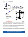
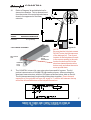
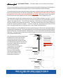
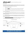
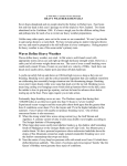
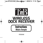
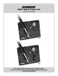
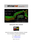
COASTAL
IN-BOOM FURLING SYSTEM
MAY 19, 2011
Installation Manual
1
COASTAL
TABLE OF CONTENTS
Page
Number
3.
Disclaimer
4.
Components packing list & required tools
5.
Gooseneck bracket location
6.
Installation – sail track
7.
Location of luff track top cap
8.
Flexible feeder fitting instructions
9.
Mainsheet and vang bail fitting
10.
Initial check, sail fitting & your notes
11.
IMPORTANT INFORMATION TO INSTALLERS & OWNERS
FORESPAR
PRODUCTS
CORP.
22322 GILBERTO
RANCHO SANTA MARGARITA, CA 92688
PHONE 949-858-8820 FAX 949-858-0505
EMAIL [email protected]
2
COASTAL
IMPORTANT
Read this first
Installation should only be undertaken by an experienced rigger. Use safety equipment and install
during suitable conditions.
Follow the instructions in this manual. Each Leisure Furl system is custom manufactured to the
unique specifications of this vessel. If you do not understand a point in this manual, do not
guess, request advice.
We have made every effort to explain the installation process as completely as possible. Nonetheless, it is not possible to anticipate, or address every conceivable problem that might arise during
installation. Hence, we can not accept responsibility for errors or omissions in this manual. These
installation guidelines are intended to provide general guidance to an experienced rigger. For specific guidance and technical support, contact the person who sold you the Leisure furl system.
Specific guidance and technical support are fundamental to the installation process.
An experienced rigger should have a thorough knowledge and understanding of general rigging
installation principles. These guidelines should be read in conjunction with such other principles.
Such principles shall be deemed to supplement these guidelines.
Installation of the Leisure furl system is entirely at your own risk. We accept no liability for
personal injury or property damage resulting from faulty installation. Nor do we accept warranty
claims resulting from faulty installation. Do not install a Leisure furl system except on the boat for
which it was specifically designed and manufactured.
The Vang Lug & Sheet Bails
All vang lugs and sheet bails are shipped loose and should be positioned during the installation
process. This allows for the most precise location of these fittings.
IT IS VERY IMPORTANT THAT THE SAIL COVER BE PULLED TO THE
TOP OF THE BOOM PRIOR TO FASTENING THE VANG LUG AND SHEET
BAILS. THIS WILL PREVENT DAMAGING THE SAIL COVER DURING
THE DRILLING & TAPPING PROCESS.
Line controlled vangs like the Forespar® Yacht RodTM should be setup to raise the boom above the
87o angle when the line is released.
Boom vangs & topping lifts
In-boom furling systems require both a rigid boom vang and a traditional boom topping lift for safety
and ease of sail trimming. When furling or reefing, the boom should be adjusted to the required 87o
angle and held at that angle with the support of the boom vang during the furling process. In heavy
weather the boom topping lift should be used to arrest the motion of the boom during furling.
When the boat is moored a boom topping lift will extend the life of your boom vang, no matter what
type; spring, pneumatic, hydraulic or electric.
3
COASTAL
PACKING LIST
Leisure furl boom
Furling mandrel
Gooseneck bracket assembly
Luff track base extrusions
Bolt rope foil sections
Threaded luff slugs
Feeder assembly
Luff track sheave
1/4-20 machine screws
Vang lug
Mainsheet bails
Sail cover
Furling line
Owner’s manual
Sailmaker’s Instructions (unless sent to sailmaker by Forespar®)
TOOLS REQUIRED
1/4-20 taps
Drill bits sizes #7 or 3/16”
Hack saw
Screwdriver (phillips)
Measuring tape
Center punch
Tap wrench
Electric drill motor
Electric grinder 4” (to remove the existing gooseneck bracket, and fair the area)
Winch handle
Boson’s chair
LanocoteTM or similar anti-corrosion compound
LocTite
4
COASTAL
25”
34”
Diagram 1
ITEMS NOT SHOWN
Sail Cover
Luff Track Halyard Sheave
Furling Line
Sheet Bails
Use LocTite on all gooseneck
fitting to mast fasteners
Diagram 2
Note that Diagram 1 shows the location of the base extrusion 34” above the Datum point
which is the center of the furling mandrel. The flexible feeder portion of the sail track extends
25” below the end of the base extrusion. The lower base of the ‘P’ dimension is the top of the
furling mandrel, 1-1/2” above Datum.
Refer to Diagram 2 for the vertical dimensional relationship between the gooseneck bracket,
datum and the bottom of the boom. When replacing a standard boom, the Leisure furl gooseneck does not need to be located where the original fitting was.
Considerations for desired boom location are sail hoist ‘P’ dimension, vang angle, dodger
and head clearance. Remember, when sailing to weather, the boom can be sheeted below
the 87o required furling angle.
5
COASTAL
For installation to a new vessel, the positioning of the gooseneck will be determined
as per the information on page 6. It is wise to measure “P” from the top of “P” to the
bottom of “P”. This will confirm the gooseneck position as per Diagram 1.
In all instances it would be preferable to check with the owner, the preferred position,
because of the greater depth of the boom.
INSTALLATION INSTRUCTIONS – fitting the sail track, track slugs
1.
After confirming the gooseneck position make a reference mark for the
position datum which is the center of the furling mandrel.
2.
Measure and mark a position 34” above datum that the base extrusion will finish.
(See Diagram 1)
3.
Luff track and track base must be installed before any other fittings are
attached to the aft face of the mast.
4.
Insert 18 or more mounting slugs into the mast luff slot, raise to a convenient
waist level and place a piece of masking tape across slot to hold up the slugs.
5.
Hold the 6’ track base that has the sheave box attached against the back of the mast
and thread one of the ¼-20 machine screws through the base into the top slug.
6.
While pushing the track base upward as you work, engage a slug for each hole in
the base.
7.
When the first set of slugs are installed, send the first base section to the person at
the masthead for tightening in place while the second track base is being prepared
below. Position this first section of track at the top of the mast. Refer to diagram 3a
for the location in relation to the main halyard sheave.
7A.
Alternately, if you are working alone, once you have raised this first section to the top
of the mast and fixed it in place, you can install successive sections pushing them up
the mast as you progress. It would be helpful to have a 4-foot and a 6-foot length of
wood or electrical conduit to prop up the sections as you work. The base weighs
.49 lbs./ft., or 25 lbs./50 ft.
8.
Introduce more slugs into the mast luff slot as needed. Progressively add track base
sections until there is no more than 6 feet left to the bottom track mark. Tighten all
these sections in place making sure each joint is well aligned.
9.
Cut the final PVC luff track to length so the lower end is 9” above datum and
tighten in place.
6
COASTAL
10.
Refer to Diagram 3a and table below for
sheave box location. This is dimensioned
from the center of the main halyard sheave
down to the upper end of the base
extrusion.
SYSTEM
SERIES
SHEAVE TO BASE
REFERENCE DIMENSION
COASTAL
6.0” [152mm]
Diagram 3a
LUFF TRACK ASSEMBLY
BOLT ROPE
FOIL
THREADED
LUFF
SLUG
11.
ALUMINUM
BASE
EXTRUSION
NOTE:
Be sure that the link plate screws
DO NOT enter the boltrope area
of the boltrope foil. The correct
location of the link plate will result
in the screws seating in the web.
Anchor the bolt rope foil to the
aluminum base extrusion at the
bottom only, and allow the rest to
move up and down.
The COASTAL Leisure furl uses a two piece base and foil system. The foil
portion is an extrusion of UHMW-PE high tensile polymer. After mounting the
aluminum base extrusion, with the .020 space as shown below, slide on the foil.
The foil pieces can simply be joined by butting them together. Due to thermal
expansion of the polymer bolt rope foil; a gap of 1” must be left between the top
end of the foil and the bottom of the halyard sheave box.
7
COASTAL – Flexible feeder limit line fitting instructions
The limit line assembly consists of two stainless steel termination blocks and a fixed length of
SpectraTM line which passes through the eye on the forward face of the luff feeder.
To install the limit line termination blocks on the mast, position the port and starboard blocks
at an equal distance from the aft face of the mast. The limit line should be loose enough
to allow the track to flex port and starboard but not aft. With that in mind, the termination blocks should be installed on the mast sides as shown in the diagrams 4 & 5.
The termination blocks are installed using the 1/4-20 FHMS provided, use an F or 3/16”
drill. The knot in each end of the limit line must be pushed out of the termination block to
expose the fastener hole. This will allow marking of the mast for drilling and tapping, as
well as installing and tightening the screw. This may require flexing the track forward to
install the second termination block. A piece of light line, tied around the mast and luff
track, may be handy here to hold the track in the forward flexed position.
Each installation is a little different, and the desired amount of flex has to be determined by
hoisting and furling the sail. The furling operation should be done several times with eyes on
the luff of the sail. Ensure that the 87o boom angle is correct, then watch as sail the rolls into
the boom. Furling should be checked at different angles to the wind, since this is the true test
of the flexible feeder setup.
TRACK BASE
Once the termination blocks have been
6” Minimum
installed on the mast, the only way
to effect the amount of flex in the
unsupported portion of the luff track
is to change the length of the limit line.
If less flex is deemed necessary the
line can be shortened.
If a longer line is required for
FLEXABLE FEEDER
additional flex, SpectraTM
line can be purchased
from your local chandlery.
S/S LUFF FEEDER
Use a figure eight stopper
knot in each end then trim
Diagram 4
SIDE VIEW
the ends as necessary.
S/S 10-24 X 1/2”
SCREW TO SECURE
THE BOTTOM BOLT
ROPE FOIL TO THE
BASE EXTRUSION
ONLY THE BOTTOM
LENGTH OF BOLT ROPE
FOIL IS FIXED TO THE
BASE
TERMINATION BLOCK
LIMIT LINE
Diagram 5
BOTTOM VIEW
8
Main Sheet and Vang Bail fitting instructions
BAIL FITTING
When fitting the mainsheet and vang bails in the track the bails must be secured using the
special dog set screws that have been provided. Be sure to pull the sail cover to the top of the
boom to prevent damage from drilling into the lower cavity.
1.
Position the bail in the track.
2.
Tighten the pointed dog set screw (one provided) to mark the location for drilling.
3.
Slide the bail out of the way, and drill the 9/64” hole through the top of the track.
4.
Position the bail using a standard dog set screw in the first hole then mark and drill the
next hole as in steps 2 & 3.
5.
When all the holes have been drilled for the bail, use Loc-Tite on the dog and the
threads of each set screw, and tighten. The dog set screws must be used at every threaded
fastening point of the bail.
6.
When tight, the set screws force the bail tight against the underside of the track. The
dogs lock into the drilled holes which secures the bail against the thrust loads, preventing the
bail from sliding in the track.
All bail set screws must remain tight. Checking these screws should be a part of the
7.
regular preventative maintenance inspections on your Leisure FurlTM boom.
LOWER CAVITY AREA
TOP OF TRACK
DRILL THESE HOLES
DOG
DOG SET
SCREW
SHEET BAIL
9
COASTAL
INITIAL CHECK
Ensure the furling mandrel rotates freely.
Ensure that boom is at correct, 87 degree angle.
SAIL FITTING
1.
Attach first the tack to the furling mandrel, leaving around 1” between the tack
web and tack ring.
2.
Now lash the clew to the outhaul saddle on the mandrel. Do not pull the foot out
tight, leave fullness in the foot for efficient down wind sailing. The built-in sail foot
controls will generate outhaul tension..
3.
The clew lashing must take multiple wraps around the furling mandrel to
eliminate the up-load on the pad eye.
4.
Hoist the sail up the mast.
5.
Roll the sail onto the port side of the mandrel. (We recommend two persons assist
by pulling either the luff or leach, so as to ensure the bolt rope remains in the area
between the boom edge and the mast, whilst the sail is being furled).
COASTAL - Installation Notes
10
COASTAL
Important information for both installers and owners.
Do not raise the boom with the topping lift or vang more
than 2 feet from the normal operating angle, as the mandrel
will bottom out on the boom aft end plate and cause damage.
If it is essential to do this, the mandrel must be disconnected
from the universal.
If the boom is dropped down to the deck for any reason ensure that the mandrel has not dropped off the aft end spigot
before raising the boom again with the vang or topping lift.
If it is necessary to furl downwind pull the boom in to 45
degrees before commencement. This decreases the load in
the sail, gets the sail off the shrouds and spreaders and increases the efficiency of the furl.
If a topping lift only is being used to support the boom, tie a
knot in the topping lift line aft of the rope clutch or cleat to
ensure that if someone accidentally releases the topping lift
cleat the boom doesn’t crash down and cause damage or hurt
someone.
Ensure all track joints are smooth and radiused. The track
entrance from the sail feeder is particularly important.
Ensure that there is nothing on the mast in the area that the
sail rolls that could possibly cause sail chafe. This could
include fittings around the side of the mast and trisail tracks.
11