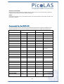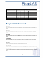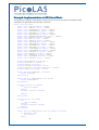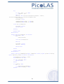
1
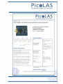
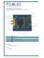
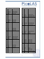
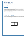
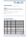
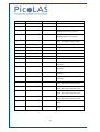
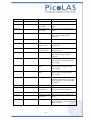
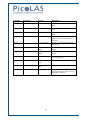
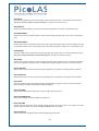
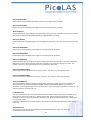
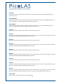
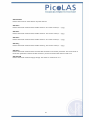
User Manual
preliminary
PLCS-40
Distributor:
1
Rev. 13.
13.02
Table of Contents
Table of Contents...............................................................................................................................2
Description of Connections ................................................................................................................4
How to get started .............................................................................................................................6
Operating Modes ............................................................................................................................... 7
Pulse output stage .............................................................................................................................8
Pulse Jitter ....................................................................................................................................... 10
External Trigger Delay ..................................................................................................................... 10
12-bit ADC ....................................................................................................................................... 11
16-bit DAC ....................................................................................................................................... 11
Mechanical Dimensions ................................................................................................................... 12
Controlling the PLCS-40 Using a PLB-21 .......................................................................................... 13
Controlling the PLCS-40 via PC ........................................................................................................16
Electrical Characteristics .................................................................................................................. 37
Absolute Maximum Ratings ............................................................................................................. 37
2
3
Description of Connections
The following drawing shows all connections which are available to the user.
Figure 1: Connectors of the PLCS-40
Connector 1
upper pin header
Connector 2
signal output (not working in current version)
Connector 3
signal output (MMCX connector, not working in current version)
Connector 4
signal output (SMC connector)
Connector 5
trigger input (5V into 50Ohms)
Connector 6
lower pin header
Green LED:
- On: OK
- Off: PLCS-40 not operational
Red LED:
- On: Error
- Off: OK
4
Connector 1 (upper pin header)
Connector 6 (lower pin header)
Pin
Name
description
Pin
Name
description
1
Vcc (15V)
supply voltage input
1
+5 V
output, max 10mA
2
Vcc (15V)
supply voltage input
2
+5 V
output, max 10mA
3
Vcc (15V)
supply voltage input
3
GND
ground
4
Vcc (15V)
supply voltage input
4
GND
ground
5
GND
power ground
5
reserved
do not connect
6
GND
power ground
6
+3,3V
output, max 10mA
7
reserved
do not connect
7
DA_CH 3
digital-analogue output 3
8
reserved
do not connect
8
DA_CH 4
digital-analogue output 4
9
reserved
do not connect
9
DA_CH 1
digital-analogue output 1
10
reserved
do not connect
10
DA_CH 2
digital-analogue output 2
11
reserved
do not connect
11
IO 3
digital IO 3
12
reserved
do not connect
12
IO 4
digital IO 4
13
reserved
do not connect
13
IO 1
digital IO 1
14
GND
signal ground
14
IO 2
digital IO 2
15
reserved
do not connect
15
RS232_TX
serial connection TxD
16
reserved
do not connect
16
RS232_RX
serial connection RxD
17
n.c.
do not connect
17
+12V
output, max 50mA
18
n.c.
do not connect
18
+12V
output, max 50mA
19
n.c.
do not connect
19
GND
ground
20
n.c.
do not connect
20
GND
ground
21
n.c.
do not connect
21
AD_CH 3
analogue-digital input 3
22
n.c.
do not connect
22
AD_CH 4
analogue-digital input 4
23
n.c.
do not connect
23
AD_CH 1
analogue-digital input 1
AD_CH 2
analogue-digital input 2
24
n.c.
do not connect
24
25
n.c.
do not connect
25
GND
ground
26
n.c.
do not connect
26
GND
ground
27
TRG_TTL -
trigger input ground
27
reserved
do not connect
28
TRG_TTL -
trigger input ground
28
reserved
do not connect
29
TRG_TTL +
trigger input into 500R
29
reserved
do not connect
30
TRG_TTL +
trigger input into 500R
30
reserved
do not connect
41
TRG -
trigger input ground
41
reserved
do not connect
42
TRG -
trigger input ground
42
reserved
do not connect
43
TRG +
trigger input into 50R
43
reserved
do not connect
44
TRG +
trigger input into 50R
44
reserved
do not connect
45
TRG -
trigger input ground
45
reserved
do not connect
46
TRG -
trigger input ground
46
reserved
do not connect
47
GND
signal ground
47
reserved
do not connect
48
GND
signal ground
48
reserved
do not connect
49
n.c.
do not connect
49
reserved
do not connect
40
n.c.
do not connect
40
reserved
do not connect
41
GND
signal ground
41
GND
ground
42
GND
signal ground
42
GND
ground
43
signal output
analogue/digital into 50R
43
n.c.
do not connect
44
signal output
analogue/digital into 50R
44
n.c.
do not connect
45
GND
signal ground
45
LED_1
open collector red LED
46
GND
signal ground
46
LED_2
open collector green LED
5
How to get started
Step #
What to do
Note
1
Unpack your Device
2
Optional: Connect your Scope to the signal
output. (SMC jacket)
3
Connect the serial lines to a PC / PLB-21. The
PLCS-40 cannot be used without this
See connector 6, page 5
4
Connect the power supply
See connector 1, page 5
5
Optional: Connect an external trigger source
6
Power on your device
7
When the initializing is done, adjust the pulse
parameters to your needs.
See “Controlling the PLCS-40 using the PLB-21 /
PC”
8
Activate the output
6
Operating Modes
The PLCS-40 can be operated in two different ways: As a digital pulse generator with various trigger
functions and as an analogue pulse generator. Both modes are described below: Please note that the
PLCS-40 only support rectangular pulse output in digital mode.
Using the PLCS
PLCSDigital Function Generator
LCS-40 as a Digital
The PLCS-40 will automatically put into the digital mode by selecting the appropriate trigger mode in the
LSTAT register. The pulse width, repetition rate, number of pulses to be generated and the trigger modes
can be controlled via several registers. Please see chapter “Trigger Modes” for more information about the
usage of the trigger functions.
Using the PLCSPLCS-40 as a Analogue Function Generator
The PLCS-40 will automatically put into the analogue mode by selecting the appropriate trigger mode in
the LSTAT register. The pulse width can be controlled in steps of 5ns to a maximum of 320ns. Each step
needs two 16-Bit data words as the DAC is updated every 2.5ns. Hence, to generate a complete pulse of
320ns width 128 data words need to be programmed. The following diagram shows a pulse example:
7
Pulse output stage
The schematic of output circuit is shown in Figure 2. The output amplifier will generate a square-wave
signal with an amplitude of 6,6V. If a 50 Ohm load is attached to connectors 2, 3, or 4 this will result in a
signal level of 3.3V at the load. Unlike the trigger inputs the output circuit is not galvanically isolated from
the power supply. To obtain a well-formed signal a load of 50 Ohm is recommended. Refer to the electrical
characteristics on chapter “Electrical Characteristics” for further details.
Figure 2: Pulse output circuit
8
Trigger Modes
Modes
The PLCS-40 supports a number of trigger modes which are described below. These does only affect the
digital function generator. The width and repetition rate of the pulses generated are user defined. Pulses
will always be generated as long as the trigger condition matches and the laser is enabled.
As an input for the trigger signal the connector 5 or the upper pin header can be used. Figure 3 shows the
schematic of both inputs. Note that they are galvanically isolated from the supply voltage. For trigger
levels see the electrical characteristics on chapter “Electrical Characteristics”.
Important: Never use both trigger inputs at the same time. Correct operation is not ensured if
both inputs are connected to a source. Furthermore, a signal fed into one input may result in a
current flowing out of the other input. This might damage your trigger source.
In the following the different trigger modes are described separately:
Edge
In this mode an external trigger source is required to generate pulses. The pulses can either be generated
on the rising or the falling edge of the supplied trigger. On each edge which equates the given setting, a
given number of pulses (“Shots”) will be generated.
Pulse
In this mode an external trigger source is required to generate pulses. The PLCS will generate pulses
during the positive or negative part of the trigger source.
Internal
In this mode the external trigger source is ignored. The PLCS will generate an infinite number of pulses by
itself.
Figure 3: Trigger input circuit
9
External Trigger
Pulse Positive
Pulse Negative
..
..
..
..
..
..
Edge Rising
.. Edge Falling
Figure 4: Schematic pulse diagram
Pulse Jitter
The following table shows the typical jitter values for the pulse to pulse and the pulse length jitter. These
are identical for all trigger modes as the pulses are generated the same way.
typ. jitter
250ps
250ps
pulse to pulse
pulse length
External Trigger Delay
The following table shows the typical delay times between a trigger event on the external trigger input
and the response on the pulse output.
trigger mode
pulse, negative
pulse, positive
edge, negative
edge, positive
dac
typical delay
175ns
86ns
175ns
86ns
40-45ns
10
12-bit ADC
The PLCS-40 is equipped with four 12-bit ADC channels. These can be read out by the user using the PLB21 or the appropriate serial commands. The ADC input pins are protected by clamping diodes in order to
provide ESD protection.
The PLCS-40 uses its internal +3,3 V supply and the system ground as analogue reference points. The +3,3
voltage is available on an external pin, but must not stressed with more than a few milliamperes.
16-bit DAC
The PLCS-40 is equipped with a additional four channel 16-bit digital to analogue converter which is
accessible by the user. The +3,3 V supply and the system ground as analogue reference points. The +3,3
voltage is available on an external pin, but must not stressed with more than a few milliamperes.
11
Mechanical Dimensions
The following dimensions are in millimetres (mm).
A
59,2
a
2,4
B
54,3
b
2,4
C
48,3
c
3,9
D
44
d
60,4
E
33,8
e
2,54
F
23,3
f
2,54
G
4,9
12
Controlling the PLCS-40 Using a PLB-21
To control the PLCS-21 with a PLB-21 it must be connected via the enclosed cable. The PLB-21 will not
work if both, the USB and the PLB-21, are connected the same time.
When the PLB-21 is connected the first time to a PLCS-21 you are asked to download a new driver. This
must be confirmed with “yes” for the PLB-21 to work properly.
Menu Structure
The following diagram shows the structure of the PLB-21 menu which affects the PLCS-21. All entrys are
described in detail. All other menu entries are described in the PLB-21 manual. For detailed instructions
see the PLB-21 manual.
Menu root
-
Pulseparameter
o Width
o Reprate
-
Trigger
o Mode
o Logic
o Shots
-
Analogue
o Form
o Length
o Delay
-
Data
o
o
o
-
-
-
Form
Pos
Value
Adc
o
o
o
o
o
Vcc
Ch0
Ch1
Ch2
Ch3
o
o
o
o
DAC Ch0
DAC Ch1
DAC Ch2
DAC Ch3
Dac
Temperature
o Dev. Off
o Dev. Max
o Dev. Act
o PLCS Act.
13
Pulseparameter
In this menu point you can modify the pulse length and repetition rate. Please note that these values are
not used in every trigger mode.
Width
This value defines the pulse width in nano seconds (ns). The minimum and maximum values are defined by
the actual repetition rate.
Reprate
This value defines the repetition rate in Hertz (Hz). The actual minimum and maximum values depend on
the given pulse width.
Trigger
The PLCS-40 supports a number of trigger modes. For a detailed description of each mode see chapter
“Trigger modes”.
Mode
This selects the used trigger mode.
Logic
This option is only used when the trigger mode is either “edge” or “pulse”. In “edge” mode you can select if
pulses should be generated on the rising or falling edge of the supplied trigger. In “pulse” mode it selects
weather pulses should be generated on “positive” (high) or the “negative” (low) part of the trigger signal.
Shots
When using the edge mode, the number of generated pulses can be determined by the user. The given
number of pulses will always be generated, even if another trigger is received during generation.
Analogue
The PLCS-40 supports the generation or analogue pulse forms. This is configured in this submenu
Form
This selects the used analogue pulse form data storage. See chapter “Analogue pulse generation” for
more information.
Length
This selects the length of the generated analogue pulse. See chapter “Analogue pulse generation” for
more information.
Delay
This selects the delay of the generated analogue pulse. See chapter “Analogue pulse generation” for more
information.
14
Data
The PLCS-40 supports the generation or analogue pulse forms. The required data can be altered within
this submenu.
Form
This selects the analogue pulse form which should be altered.
Pos
This selects the data field which should be altered.
Value
This shows and alters the selected data field.
Adc
The PLCS-40 is equipped with several ADC channels. These can be monitored here
Vcc
This value shows the current supply voltage.
Ch 0 … 3
This value shows the current ADC value of the desired channel. Please see chapter “ADC “ for more
information.
Dac
The PLCS-40 is equipped with four 16-bit DAC channels. These can be set here.
DAC Ch 0 … 3
This value selects the DAC output value. Please see chapter “DAC” for more information.
Temperature
The PLCS-40 is equipped with an onboard NTC sensor to monitor the PCB temperature. This can be done
here
15
Controlling the PLCS-40 via PC
Introduction
In addition to being able to connect up a PLB-21, the PLCS-40 can also communicate with a
computer/laptop. This interface allows communications over both a serial text interface as well as using
the PicoLAS protocol. While the text interface is designed for communication with a terminal program,
the PicoLAS protocol is designed as a system interact protocol.
The switching between the two protocols occurs automatically as soon as the PLCS-40 receives a certain
sequence. The corresponding commands are:
•
PING for the PicoLAS protocol
•
“init” followed by <Enter> for the text interface
Description of the Serial Interface
The PLCS-40 implements a standard RS232 serial interface. A simple 3-wire connection is required for the
communication. The connection settings are:
Baud rate
115200
Data bits
8
Stop bits
1
Parity
even
16
The Serial Text Interface
The following section describes the structure and commands of the text interface.
Structure
Every command that is sent to the PLCS-40 must be completed with a CR (Enter). It consists of a
command word followed by a parameter. If the command was successfully executed then an “0” is sent,
otherwise a “1”. If the command requires an answer parameter, this parameter is sent before the
confirmation is given.
Example:
The user would like to read out the voltage currently being used by the pulser.
User input:
ghwver<Enter>
Output of the PLCS-21:
1.0.0
0
Input is done in ASCII code and is case sensitive. Every terminal can be used that supports this standard.
Commands for the PLCSPLCS-40
The following table contains a command reference for the PLCS-40.
Command
Parameter
Answer
Description
help
--
Help text
Returns of a help text
ghwver
--
Hardware version
Returns a hardware version string
gswver
--
Software version
Returns a software version string
gserial
--
serial number
Returns the device serial number
gname
--
device name
Returns the device name
ps
--
current settings
Prints out the current device settings
loaddef
--
--
Load previously saved default values
savedef
--
--
Save current settings as default values
gerrtxt
--
Error text
Returns the content of the ERROR
register in readable form
gerr
--
ERROR register
Returns the content of the ERROR
register
clrerr
--
--
Clears any pending error condition
glstat
--
LSTAT register
Returns the content of the ERROR
register
slstat
number
LSTAT register
Sets the LSTAT register to the given
value
17
Command
Parameter
Answer
Description
lon
--
--
Enables the pulse output
loff
--
--
Disables the pulse output
enautodef
--
--
Enables the automatic loading of the
defaults values every start-up
disautodef
--
--
Disables the automatic loading of the
defaults values every start-up
strgmode
trigger mode
trigger mode
Sets the trigger mode to the given
value. See chapter trigger modes.
gtrgmode
--
trigger mode
Returns the current trigger mode
gad0
--
ADC value
Returns the ADC value of channel 0
gad1
--
ADC value
Returns the ADC value of channel 1
gad2
--
ADC value
Returns the ADC value of channel 2
gad3
--
ADC value
Returns the ADC value of channel 3
gaduin
--
Supply voltage
Returns the current supply voltage
gda0
--
DAC value
Returns the current DAC value of
channel 0
gda1
--
DAC value
Returns the current DAC value of
channel 1
gda2
--
DAC value
Returns the current DAC value of
channel 2
gda3
--
DAC value
Returns the current DAC value of
channel 3
sda0
DAC value
DAC value
Sets the DAC channel 0 to the given
value. Returns the new DAC value.
sda1
DAC value
DAC value
Sets the DAC channel 1 to the given
value. Returns the new DAC value.
sda2
DAC value
DAC value
Sets the DAC channel 2 to the given
value. Returns the new DAC value.
sda3
DAC value
DAC value
Sets the DAC channel 3 to the given
value. Returns the new DAC value.
gdamin
--
minimal DAC value
Returns the minimal possible DAC
value
gdamax
--
maximal DAC value Returns the maximal possible DAC
value
18
Command
Parameter
Answer
Description
gwidth
--
current pulse width
Returns the current pulse width
gwidthmin
--
minimal possible
pulse width
Returns the minimal possible pulse
width
gwidthmax
--
maximal possible
pulse width
Returns the maximal possible pulse
width
swidth
pulse width
pulse width
Sets the pulse width to the given
value. The new pulse width is
returned.
greprate
--
current repetition
rate
Returns the current repetition rate
grepratemin
--
minimal possible
repetition rate
Returns the minimal possible
repetition rate
grepratemax
--
maximal possible
repetition rate
Returns the maximal possible
repetition rate
sreprate
repetition rate
repetition rate
Sets the repetition rate to the given
value. The new pulse width is
returned.
number of pulses
Returns the configured number of
pulses, that should be generated on
every trigger
Returns the minimal number of
pulses, that can be generated on
every trigger
gcount
--
gcountmin
--
minimal number of
pulses
gcountmax
--
maximal number of Returns the maximum number of
pulses
pulses, that can be generated on
every trigger
scount
number of pulses
number of pulses
Sets the number of pulses that
should be generated on every trigger
to the given value. The new number
is returned.
gtemp
--
PCB temperature
Returns the actual PCB temperature
gtempmax
--
maximum PCB
temperature
Returns the maximum PCB
temperature before shutdown
gform
--
puls form number
Returns the actual puls form number
gformcnt
--
number of possible
puls forms
Returns the number of different puls
forms
sform
puls form number
puls form number
Sets the puls form set point to the
given number. The new selected puls
form is returned
19
Command
Parameter
Answer
Description
gdelay
--
delay
Returns the configured DAC output
delay
gdelaymin
--
minimum delay
Returns the minimum possible delay
value
gdelaymax
--
maximum delay
Returns the maximum possible delay
value
sdelay
delay
delay
Sets the DAC output delay to the
given value. The new delay value is
returned
glength
--
DAC puls length
Returns the actual configured DAC
puls length
glengthmin
--
minimum DAC puls
length
Returns minimum possible DAC puls
length
glengthmax
--
maximum DAC puls Returns maximum possible DAC puls
length
length
gdata
<form> <pos>
data value
Returns the data value of the given
form and position.
gdatamin
--
minimal valid data
value
Returns the minimal valid data value
gdatamax
--
maximal valid data
value
Returns the maximal valid data value
sdata
<form> <pos> <data>
data value
Sets the data of the given form and
position to the given value. The new
data value is returned
20
If an Error Occurs
If an error occurs during operation the pulse output is switched off and a message is sent to the terminal.
Errors have to be acknowledged with “clrerror” otherwise switching on again of pulse output is not
possible. Note that warnings are also displayed this way but these do not switch off pulse output. Hence it
is not necessary to aknowledge warnings with “clrerror”.
This message has this format:
err: <Error Register>
The parameter <Error Register> represents the content of the ERROR register in binary form.
21
The PicoLAS Protocol
The following section describes the structure and possible commands of the PicoLAS protocol.
Structure
Each transmission consists of 12 bytes – called a frame as follows – which must be sent consecutively.
Otherwise the system times out and the transmission must start again from the beginning.
A frame has a fixed structure. The first two bytes describe the command, the following eight bytes the
parameters, followed by one reserved byte and one checksum byte. The checksum is calculated out of the
first 11 bytes which are linked by a bitwise XOR.
Thus a frame has the following structure:
Byte
Meaning
1
Bit 8-15 of the command
2
Bit 0-7 of the command
3
Bit 56-63 of the parameter
4
Bit 48-55 of the parameter
5
Bit 40-47 of the parameter
6
Bit 32-39 of the parameter
7
Bit 24-31 of the parameter
8
Bit 16-23 of the parameter
9
Bit 8-15 of the parameter
10
Bit 0-7 of the parameter
11
Reserved, always 0x00
12
Checksum
A properly received frame must be acknowledged by the recipient with an answer, which is also a frame. If
the acknowledgement does not occur then the command has not been processed and the sending
procedure should be repeated.
If the recipient recognizes the command as valid, but not the parameters, then it will answer with a
ILGLPARAM (0xFF12) as command.
In the case that the recipient receives an invalid command it will answer with UNCOM (0xFF13).
If a faulty checksum is recognized then the answer is RXERROR (0xFF10). If this error occurs often then the
connection should be checked.
Using the REPEAT (0xFF11) command the recipient can instruct the sender to send the most recent frame
again.
22
23
General Commands
The following list contains an overview of the general commands which are supported by every product
from PicoLAS which makes use of this protocol. The explanation of the individual commands is given
further below.
Command Name
Sent Frame
Answer Frame
Command
Parameter
Command
Parameter
PING
0xFE01
0
0xFF01
0
IDENT
0xFE02
0
0xFF02
ID
GETHARDVER
0xFE06
0
0xFF06
Version
GETSOFTVER
0xFE07
0
0xFF07
Version
GETSERIAL
0xFE08
0 … 255
0xFF08
Refer to description
GETIDSTRING
0xFE09
0 … 255
0xFF09
Refer to description
GETDEVICECHECKSUM
0xFE0A
0
0xFF0A
CRC16 checksum
RESET
0xFE0E
0
0xFF0B
0
PING
Is used to determine the presence of a connected recipient and to initialize the interface of the recipient
for this protocol. Has no effect on the condition of the recipient. The command parameter is always 0, the
answer parameter too.
IDENT
It is used to determine the device ID of an attached recipient. Has no effect on the condition of the
recipient. The parameter is always 0. The answer contains the ID.
GETHARDVER
Instructs the recipient to send back the version number of the hardware being used. The parameter is
always 0. The answer contains the hardware version of the recipient. The format of the answer is:
0x000000<major><minor><revision>. In other words, one byte for each of the three elements of the
version number.
As example, version 1.2.3 has the parameter 0x000000010203.
GETSOFTVER
Instructs the recipient to send back the version number of the software being used. The parameter is
always 0.
The answer contains the software version of the recipient. The format of the answer is:
0x000000<major><minor><revision>. In other words, one byte for each of the three elements of the
version number.
As example, version 2.3.4 has the parameter 0x000000020304.
GETSERIAL
Instructs the recipient to send back its serial number. If 0 is sent as parameter, the answer contains the
number of (ASCII) digits of the serial number; otherwise the respective position of the serial number is sent
in ASCII format.
GETIDSTRING
Instructs the recipient to send back the name of the device. If 0 is sent as parameter, the answer contains
the number of digits of the string, otherwise the respective position of the serial number is sent in ASCII
format.
24
GETDEVICECHECKSUM
Instructs the recipient to transmit a CRC16 checksum of its memory. This can be used to check the
integrity of the programme memory after switching on.
RESET
Instructs the recipient to carry out a software reset. This resets the device to the switch-on state. The
parameter is always 0.
Commands for the PLCSPLCS-40
The following table contains a list of the commands which the PLCS-21 supports in addition to the
generally applicable commands. An explanation of the individual commands follows afterwards.
Command
Sent Frame
Received Frame
Command
Parameter
Command
Parameter
GETLSTAT
0x0010
0
0x0110
LSTAT register
SETLSTAT
0x0011
LSTAT register
0x0110
LSTAT register
GETERROR
0x0020
0
0x0120
ERROR register
CLEARERROR
0x0021
0
0x0120
0
GETWIDTH
0x0030
0
0x0130
pulse width in ns
GETWIDTHMIN
0x0031
0
0x0130
pulse width in ns
GETWIDTHMAX
0x0032
0
0x0130
pulse width in ns
GETWIDTHSTEPSIZE
0c0033
0
0x0130
size of one pulse
width step
SETWIDTH
0x0034
pulse width in ns
0x0130
pulse width in ns
GETREPRATE
0x0035
0
0x0130
reprate in Hz
GETREPRATEMIN
0x0036
0
0x0130
reprate in Hz
GETREPRATEMAX
0x0037
0
0x0130
reprate in Hz
GETREPRATESTEPSIZE 0x0038
0
0x0130
size of one reprate
step
SETREPRATE
0x0039
reprate in Hz
0x0130
reprate in Hz
GETCOUNT
0x003A
0
0x0130
number of pulses
GETCOUNTMIN
0x003B
0
0x0130
number of pulses
GETCOUNTMAX
0x003C
0
0x0130
number of pulses
GETCOUNTSTEPSIZE
0x003D
0
0x0130
size of one number
step
SETCOUNT
0x003E
number of pulses
0x0130
number of pulses
GETPULSFORM
0x040
0
0x0140
current selected pulsform
25
Command
Sent Frame
Received Frame
Command Parameter
Command Parameter
GETPULSFORMCOUNT
0x0041
0
0x0140
number of pulse forms
SETPULSFOM
0x0042
pulse form
0x0140
pulse form
GETPULSDELAY
0x0043
0
0x0140
delay
GETPULSDELAYMIN
0x0044
0
0x0140
minimal delay
GETPULSFORMMAX
0x0045
0
0x0140
maximal delay
SETPULSDELAY
0x0046
delay
0x0140
delay
GETPULSLENGTH
0x0047
0
0x0140
pulse length
GETPULSLENGTHMIN
0x0048
0
0x0140
minimal pulse length
GETPULSLENGTHMAX
0x0049
0
0x0140
maximal pulse length
SETPULSLENGTH
0x004A
pulse length
0x0140
pulse length
GETPULSFORMDATA
0x004B
see text
0x0140
pulse form data
SETPULSFORMDATA
0x004C
see text
0x0140
pulse form data
GETPULSFORMDATAMIN
0x004D
0
0x0140
minimal valid data value
GETPULSFORMDATAMAX
0x004E
0
0x0140
maximal valid data value
GETPULSFORMDATACOUNT 0x004F
0
0x0140
number of data fields
LOADEFAULTS
0x0050
0
0x0150
load default values
SAVEDEFAULTS
0x0051
0
0x0150
save default values
GETTEMP
0x0060
0
0x0160
PCB temperature
GETTEMPWARN
0x0061
0
0x0160
temp. warning border
GETTEMPMAX
0x0062
0
0x0160
temp. shutdown border
GETDAC0
0x00B0
0
0x01B0
DAC channel 0 value
SETDAC0
0x00B1
DAC value
0x01B0
DAC channel 0 value
GETDAC1
0x00B2
0
0x01B0
DAC channel 1 value
SETDAC1
0x00B3
DAC value
0x01B0
DAC channel 1 value
GETDAC2
0x00B4
0
0x01B0
DAC channel 2 value
SETDAC2
0x00B5
DAC value
0x01B0
DAC channel 2 value
GETDAC3
0x00B6
0
0x01B0
DAC channel 3 value
SETDAC3
0x00B7
DAC value
0x01B0
DAC channel 3 value
GETDAC
0x00B8
0
0x01B0
All four DAC values
GETDACMIN
0x00B9
0
0x01B0
minimal DAC value
GETDACMAX
0x00BA
0
0x01B0
maximal DAC value
SETDAC
0x00BB
All four DAC
values
0x01B0
All four DAC values
26
Command
Sent Frame
Received Frame
Command Parameter
Command Parameter
GETADCCH0
0x00C0
0
0x01C0
ADC value channel 0
GETADCCH1
0x00C1
0
0x01C0
ADC value channel 1
GETADCCH2
0x00C2
0
0x01C0
ADC value channel 2
GETADCCH3
0x00C3
0
0x01C0
ADC value channel 3
GETADC
0x00C4
0
0x01C0
All four ADC values
GETADCUIN
0x00C5
0
0x01C0
Supply voltage
Description of the Individual Commands
GETLSTAT
This command returns the value of the LSTAT register. For a complete description of this register see
below.
SETLSTAT
This command sets the LSTAT register to the given value. The return value contains the new register
value.
GETERROR
This command returns the value of the ERROR register. For a complete description of this register see
below.
CLEARERROR
This command clears a part of the internal ERROR register. For a detailed description of the ERROR
register see below.
GETWIDTH
Returns the current pulse width of the internal pulse generator in [ns].
GETWIDTHMIN
Returns the minimum possible pulse width of the internal pulse generator. The value is measured in [ns].
GETWIDTHMAX
Returns the maximum possible pulse width of the internal pulse generator. This value depends of the
current repetition rate. Hence, any change in the repetition rate changes this value too. It is measured in
[ns].
27
SETWIDTH
Sets the pulse width of the internal pulse generator to the given value. It must be within the borders
defined by GETWIDTHMIN and GETWIDTHMAX. The value is measured in [ns].
GETREPRATE
Returns the actual repetition rate of the internal pulse generator. The value is measured in [Hz].
GETREPRATEMIN
Returns the minimum possible repetition rate of the internal pulse generator. The value is measured in
[Hz].
GETREPRATEMAX
Returns the maximum possible repetition rate of the internal pulse generator. This value depends of the
current pulse width. Hence, any change in the pulse width changes this value too. It is measured in [Hz].
SETREPRATE
Sets the repetition rate of the internal pulse generator to the given value. It must be within the borders
defined by GETREPRATEMIN and GETREPRATEMAX. The value is measured in [Hz].
GETCOUNT
Returns the number of pulses the internal pulse generator will generate as soon as it becomes enabled.
This is only used if the counting mode is enabled. See chapter “trigger modes” for more information.
GETCOUNTMIN
Returns the minimal number of pulses the pulse generator can produce if counting mode is enabled.
GETCOUNTMAX
Returns the maximal number of pulses the pulse generator can produce if counting mode is enabled.
SETCOUNT
Sets the number of pulses the pulse generator will generate to the given value. It must be within the
borders defined by GETCOUNTMIN and GETCOUNTMAX.
GETPULSFORM
Returns the actual selected pulse form of the analogue pulse generator.
GETPULSFORMCOUNT
Returns the available number of different pulse forms.
SETPULSFORM
Sets the set point pulse form of the analogue pulse generator to the given value. This value must not be
greater than the return value of the GETPULSFORMCOUNT command.
GETPULSDELAY
Returns the actual configured delay of the analogue pulse generator.
28
GETPULSDELAYMIN
Returns the minimal available pulse delay value for the analogue pulse generator.
GETPULSDELAYMAX
Returns the maximal available pulse delay value for the analogue pulse generator.
SETPULSDELAY
Sets the pulse delay of the analogue pulse generator to the given value. This value must within the border
defined by the GETPULSDELAYMIN and GETPULSDELAYMAX command.
GETPULSLENGTH
Returns the actual configured length of the analogue pulse generator. This value is measured in steps of 5
ns.
GETPULSLENGTHMIN
Returns the minimal available pulse length for the analogue pulse generator.
GETPULSLENGTHMAX
Returns the maximal available pulse length for the analogue pulse generator.
GETPULSFORMDATA
Returns the data value of the given pulse form and position within the pulse form. The lower 16bit of the
parameter must contain the position while the next 16bit must contain the pulse form number. The
answer contains a 32-bit signed integer which represents the data value.
GETPULSFORMDATAMIN
Returns the minimal valid data value for any pulse form. The value is a 32-bit signed integer.
GETPULSFORMDATAMAX
Returns the maximal valid data value for any pulse form. The value is a 32-bit signed integer.
SETPULSFORMDATA
Sets the data field of the given pulse form and position to the given value. This value must within the
border defined by the GETPULSFORMDATAMIN and GETPULSFORMDATAMAX command. The
parameter must contain the data value in the lower 32-bit (signed integer), the position in the bits 32 … 47
and the pulse form in the bits 48 … 63.
LOADDEFAULTS
This command replaces all internal parameters with their default values. If the output is enabled during
the execution of this command, the L_ON bit of the LSTAT register will be cleared and the output
disabled. This command will fail if the CRC_DEFAULT_FAIL bit in the ERROR register I set, indicating an
error within the data.
If the DEF_PWRON bit in the LSTAT register is set, the device automatically loads these values during
power-up.
SAVEDEFAULTS
This command saves all internal parameters into an EEPROM for later usage. Use command
LOADDEFAULTS to restore them.
29
GETTEMP
Returns the actual measured PCB temperature. The value is represented in a 16bit signed integer and
measured in 0.1°C
GETTEMPWARN
Returns the temperature at which the device indicates a temperature warning in the ERROR register. The
value is represented in a 16bit signed integer and measured in 0.1°C
GETTEMPMAX
Returns the temperature at which the device indicates a temperature error in the ERROR register. The
value is represented in a 16bit signed integer and measured in 0.1°C
GETDAC0
Returns the actual configured output value of the 16-bit DAC channel 0.
SETDAC0
Sets the output value of the 16-bit DAC channel 0 to the given value. The value must be within the borders
defined by the GETDACMIN and GETDACMAX commands.
GETDAC1
Returns the actual configured output value of the 16-bit DAC channel 1.
SETDAC1
Sets the output value of the 16-bit DAC channel 1 to the given value. The value must be within the borders
defined by the GETDACMIN and GETDACMAX commands.
GETDAC2
Returns the actual configured output value of the 16-bit DAC channel 2.
SETDAC2
Sets the output value of the 16-bit DAC channel 2 to the given value. The value must be within the borders
defined by the GETDACMIN and GETDACMAX commands.
GETDAC3
Returns the actual configured output value of the 16-bit DAC channel 3.
SETDAC3
Sets the output value of the 16-bit DAC channel 3 to the given value. The value must be within the borders
defined by the GETDACMIN and GETDACMAX commands.
GETDAC
Returns the actual configured output values of all four DAC channels in one parameter. The lower 16-bit of
the answer parameter contains the DAC channel 0, the next 16-bit the DAC channel 1 and so on.
GETDACMIN
Returns the minimum valid value for any DAC channel.
30
GETDACMAX
Returns the maximum valid value for any DAC channel.
GETADC0
Returns the actual measured value of ADC channel 0. The value is within [0 … 4095]
GETADC1
Returns the actual measured value of ADC channel 1. The value is within [0 … 4095]
GETADC2
Returns the actual measured value of ADC channel 2. The value is within [0 … 4095]
GETADC3
Returns the actual measured value of ADC channel 3. The value is within [0 … 4095]
GETADC0
Returns the actual measured value of all four ADC channels in one answer parameter. The lower 16-bit of
the answer parameter contains the ADC channel 0, the next 16-bit the ADC channel 1 and so on.
GETADCUIN
Returns the actual measured supply voltage. The answer is measured in 0.1 V.
31
Description of the LSTAT Register
The following list contains a description of the individual LSTAT bits. These can be read with GETLSTAT
and written with SETLSTAT. With SETLSTAT a complete 32 bit word must always be written. Thus, to
change individual bits, first the register must be read out with GETLSTAT, then the desired bits changed
and then with SETLSTAT passed again to the PLCS.
Bit
Name
Read/Write
Meaning
0
L_ON
Read/write
Switch on/off the pulse output
1-4
TRG_MODE
Read/write
Refer to trigger modes
0 = positive edge trigger
1 = negative edge trigger
2 = internal trigger
3 = not valid -> automatically set to 2
4 = positive pulse trigger
5 = negative pulse trigger
6 = analogue pulse genetation
5
DEF_PWRON
Read/write
Indicates weather the defaults are
loaded on power-up
6
PULSER_OK
Read
When “0”, the device in an error
condition
7-31
Reserved
Read
Reserved
32
Description of the ERROR Register
The following list contains a description of the individual bits of the ERROR register.
Bit
Name
Read/Write
Meaning
0
CRC_DEVDRV_FAIL
read only
A CRC error was detected in the PLB driver. The
driver cannot be used. This does not affect the
device but the PLB.
1
CRC_DEFAULT_FAIL
read only
A CRC error was detected in the default values.
A re-save of the values should correct this.
2
CRC_CONFIG_FAIL
read only
A CRC error was detected in the internal
configuration values. Please contact your
distributor.
3
reserved
read only
reserved
4
reserved
read only
reserved
5
VCC_FAIL
read only
The supply voltage is too low or too high
6
I2C_FAIL
read only
Internal I²C error. If error persists, please contact
your distributor.
7
FAILED_TO_LOAD_DEFAULTS read only
The loading of the default failed. Normally this
is because of an pending CRC error.
8
TEMP_OVERSTEPPED
read only
The internal temperature was beyond safe
operating limits.
9
TEMP_WARNING
read only
The internal temperature is 5°C before
shutdown.
10
FPGA_FAIL
read only
Internal initialisation failure. If error
persists, please contact your distributor
Read
Reserved
11-31 Reserved
If a critical error occurs pulser emissions stop automatically. All error situations must be acknowledged or
reset with CLRERROR. Otherwise the PLCS cannot restart pulse output.
33
Example Implementation in MS Visual Basic
The following is a possible implementation of the protocol for uni-directional communications in MS
Visual Basic. No guarantee of functionality is assumed.
Public Class Protocol
Public Const PING As UShort = &HFE01
Public Const IDENT As UShort = &HFE02
Public Const GETHARDVER As UShort = &HFE06
Public Const GETSOFTVER As UShort = &HFE07
Public Const GETSERIAL As UShort = &HFE08
Public Const GETIDSTRING As UShort = &HFE09
Public Const GETDEVICECHECKSUM As UShort = &HFE0B
Public Const RESET As UShort = &HFE0E
Public Const ACK As UShort = &HFF01
Public Const IDACK As UShort = &HFF02
Public Const VERSIONACK As UShort = &HFF03
Public Const HARDVERACK As UShort = &HFF06
Public Const SOFTVERACK As UShort = &HFF07
Public Const SERIALACK As UShort = &HFF08
Public Const IDSTRINGACK As UShort = &HFF09
Public Const CHECKSUMACK As UShort = &HFF0A
Public Const RESETACK As UShort = &HFF0B
Public Const RXERROR As UShort = &HFF10
Public Const REPEAT As UShort = &HFF11
Public Const ILGLPARAM As UShort = &HFF12
Public Const UNCOM As UShort = &HFF13
Private
Private
Private
Private
Private
Private
RecParameter As UInt64 = 0
RecAnswer As UInt64 = 0
Comport As String = ""
PortOpen As Boolean = False
Serial As IO.Ports.SerialPort = Nothing
IamBusy As Boolean = False
Public Function GetAnswer() As UShort
Return RecAnswer
End Function
Public Function GetParameter() As UInt64
Return RecParameter
End Function
Property Status() As Integer
Get
Return PortOpen
End Get
Set(ByVal Value As Integer)
End Set
End Property
Property Busy() As Integer
Get
Return IamBusy
End Get
Set(ByVal Value As Integer)
End Set
End Property
Public Function Enable(ByVal port As String) As Boolean
If (PortOpen) Then
Return True
End If
34
Try
If (Not (port = "")) Then
Comport = port
End If
Serial = New IO.Ports.SerialPort(Comport, 115200,
IO.Ports.Parity.Even, 8, IO.Ports.StopBits.One)
Serial.Open()
PortOpen = True
SendReceive(Me.PING, 0, Me.ACK)
SendReceive(Me.PING, 0, Me.ACK)
Catch ex As Exception
PortOpen = False
Return False
End Try
Return True
End Function
Public Function Disable() As Boolean
If (PortOpen) Then
Try
Serial.Close()
Catch ex As Exception
End Try
PortOpen = False
Serial = Nothing
Return True
End If
Return False
End Function
Public Function SendReceive(ByVal command As UShort, ByVal param As UInt64,
ByVal expectet_answer As UShort) As Boolean
Dim Timeout As UInt32 = 10000
Dim buffer(12) As Byte
If (Not PortOpen) Then
Return False
End If
If (IamBusy) Then
Do
Application.DoEvents()
Loop While IamBusy = True
End If
35
IamBusy = True
For i As UInteger = 0 To 4
Timeout = 10000
Serial.DiscardInBuffer()
Send(command, param)
Do
Timeout -= 1
Application.DoEvents()
Loop Until ((Serial.BytesToRead() >= 12) Or (Timeout = 0))
If (Timeout > 0) Then
If (Serial.BytesToRead() >= 12) Then
If (Receive(buffer)) Then
RecAnswer = buffer(0)
RecAnswer += Convert.ToUInt16(buffer(1)) <<
RecParameter = buffer(2)
RecParameter += Convert.ToUInt64(buffer(3))
RecParameter += Convert.ToUInt64(buffer(4))
RecParameter += Convert.ToUInt64(buffer(5))
RecParameter += Convert.ToUInt64(buffer(6))
RecParameter += Convert.ToUInt64(buffer(7))
RecParameter += Convert.ToUInt64(buffer(8))
RecParameter += Convert.ToUInt64(buffer(9))
IamBusy = False
8
<<
<<
<<
<<
<<
<<
<<
8
16
24
32
40
48
56
Return (RecAnswer = expectet_answer)
End If
End If
End If
Next
IamBusy = False
Return False
End Function
Private Function Send(ByVal command As UShort, ByVal param As UInt64) As
Boolean
Dim buffer(12) As Byte
buffer(0) = command And &HFF
buffer(1) = (command >> 8) And &HFF
buffer(2) = param And &HFF
buffer(3) = (param >> 8) And &HFF
buffer(4) = (param >> 16) And &HFF
buffer(5) = (param >> 24) And &HFF
buffer(6) = (param >> 32) And &HFF
buffer(7) = (param >> 40) And &HFF
buffer(8) = (param >> 48) And &HFF
buffer(9) = (param >> 56) And &HFF
buffer(10) = 0
36
buffer(11) = CheckByte(buffer)
WriteByte(buffer)
End Function
Private Function Receive(ByVal buffer() As Byte) As Boolean
For i As UInteger = 0 To 11 Step 1
buffer(i) = ReadByte()
Next
If (buffer(11) = CheckByte(buffer)) Then
Return True
End If
Return False
End Function
Private Function CheckByte(ByVal buffer() As Byte) As Byte
Dim returnvalue As Byte = 0
For i As UInteger = 0 To 10 Step 1
returnvalue = returnvalue Xor buffer(i)
Next
Return returnvalue
End Function
Private Sub WriteByte(ByVal zeichen() As Byte)
Serial.Write(zeichen, 0, 12)
End Sub
Private Function ReadByte() As Byte
Return Serial.ReadByte()
End Function
End Class
Using this example code, a connection can be set up using the following lines of code:
Dim MyProto As Protocol = New Protocol()
MyProto.Enable(„Com3“)
MyProto.SendReceive(Protocol.PING, 0, Protocol.ACK)
37
Electrical Characteristics
Parameter
Symbol
Supply current
Condition
Min.
Typ.
US=15V, no cable/device
connected to PLCS-40
Unit
270
mA
10
50
Ohm
2,8
3
3,3
V
50
52
Ohm
515
Ohm
0.5
V
3.4
V
0.5
V
4.7
V
Load resistance (con. 2-4)
RL
Output voltage (con. 2-4)
UL
Input resistance (con. 5)
RT,50
48
Input resistance
RT,500
485
RL=50 Ohm
Max.
(accessible trough con 1)
Low Level input Voltage
(con. 5)
UT,50
US=15V
High Level input Voltage
(con. 5)
UT,50
US=15V
Low Level input Voltage
(accessible trough con 1)
UT,500
US=15V
High Level input Voltage
(accessible trough con 1)
UT,500
US=15V
0.6
0.9
2.3
3.5
Digital I/O
0
3.4
V
ADC input
0
3.4
V
ADC resolution
12
DAC output
0
DAC resolution
16
Absolute Maximum Ratings
Parameter (see figures)
Symbol
Ambient operating temperature
0°C to +55°C
Supply voltage
US
-0.3V to +19.0V
Trigger voltage on connector 5
UT,50
-6V to +6V
Trigger voltage on connector 1
UT,500
-6V to +6V
Load current on connector 2-4
IL
170mA
38
bit
3.3
V
bit