1
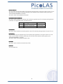
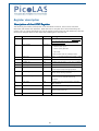
User Manual
- preliminary -
LDPLDP-C 8080-20
LDPLDP-CW 8080-20
LDPLDP-C 8080-40
LDPLDP-CW 8080-40
LDPLDP-C 120120-20
LDPLDP-CW 120120-20
LDPLDP-C 120120-40
LDPLDP-CW 120120-40
Rev. 12.09
This manual is for all pulsed C and continuous current CW driver units above.
above.
Please note the specifications
specifications are different for different units. In case of doubt please
refer to the corresponding data sheet.
Before powering on your unit, read this manual and make sure your understood it fully.
Please pay attention to all safety warnings.
If you have any doubt or suggestion, please do not hesitate to contact us!
Schulz-Electronic GmbH
Dr.-Rudolf-Eberle-Straße 2
D-76534 Baden-Baden
Fon +49.7223.9636.30
Fax +49.7223. 9636.90
[email protected]
www.schulz-electronic.de
Table of Contents
Table of Contents ....................................................................................................................... 2
Specifications.............................................................................................................................. 3
Description of Connections and Jumpers .................................................................................... 5
Interface Specification................................................................................................................. 6
Timing Diagram .......................................................................................................................... 8
Dos and Don’ts ......................................................................................................................... 10
Functional Description .............................................................................................................. 11
Test Load .................................................................................................................................. 12
Power Supply............................................................................................................................ 12
Cooling..................................................................................................................................... 12
Over Temperature Shutdown.................................................................................................... 13
Soft Start .................................................................................................................................. 13
Mechanical Dimensions ............................................................................................................ 13
Power on self test ..................................................................................................................... 15
Controlling the driver................................................................................................................ 16
Trigger Modes .......................................................................................................................... 16
Controlling the LDP-C 120-20 using a PLB-21........................................................................... 18
Controlling the LDP-C 120-20 via USB ...................................................................................... 20
Register description .................................................................................................................. 32
2
Specifications
LDPLDP-C 8080-20
LDPLDP-C 120120-20 specs to be corrected
LDPLDP-C 8080-40 specs to be corrected
LDPLDP-C 120120-40 specs to be corrected
3
LDPLDP-CW 8080-20
LDPLDP-CW 120120-20
LDPLDP-CW 8080-40 specs to be corrected
LDPLDP-CW 120120-40 specs to be corrected
4
Connecting and Interfacing
The above picture might differ in some minor details form your model.
The following drawing shows all connections which are available to the user.
LDP-C BOB
Connector
See section interface specifications for detailed information. (Break-Out-Board
connector.)
PLB
Connector for PLB-21 human interface (protected against polarity reversal)
Vin
Supply voltage (5..24V) must be 2 V above laser diode compliance voltage
GND
Supply ground
LD+
Positive laser diode output (anode). It is highly recommended to use both
connectors parallel, especially for high currents.
LD-
Negative laser diode output (cathode). Do not connect to ground It is highly
recommended to use both connectors parallel, especially for high currents.
Mini USB connector for linking the driver to a computer.
Mini USB
For a more convenient use of the driver (e.g. in laboratory use) we recommend the optional available
product accessory LDP-C-BOB or the PLB-21. Please see LDP-C-BOB and PLB-21 manual for further details.
5
Interface Specifications
The following figure shows the input and output signals of the external analogue BOB connector.
This connector can be found on the perpendicular circuit board on the right side as shown on the
previous page.
The BOB (Break Out Board) is recommended for easy testing of the driver. It will be replaced in the
application by your machine interface. The PLB-21 is a human interface that allows for full control of
all relevant device parameters.
Functional Description of BOB-Connector Interface
6
Settings and Readings
Isetpoint (Pin 10) to be completed
This input signal is used to provide an analogue setpoint value (amplitude
amplitude modulation).
modulation In order to use the
analogue setpoint, it must be configured in the PC via USB or the PLB. Please apply a voltage
corresponding to the desired current settings according to the following table:
LDP-C 80-20 : 50 A/V, range 0 - 2.0 V
LDP-C 80-40 : 50 A/V, range 0 - 1.6 Vtbd
LDP-C 120-20 : 50 A/V, range 0 - 1.6 Vtbd
LDP-C 120-40 : 50 A/V, range 0 - 1.6 Vtbd
LDP-CW 80-20 : 50 A/V, range 0 - 1.6 V
LDP-CW 80-40 : 50 A/V, range 0 - 1.6 V tbd
LDP-CW 120-20: 50 A/V, range 0 – 2.4 V
LDP-CW 120-40: 50 A/V, range 0 – 2.4 V
Idiode (Pin 9)
This signal is used as an output signal of the internal current shunt. It provides near real-time
measurement of the output current. Connect your scope and take into account the following scaling:
50 A/V
Udiode (Pin 4)
This signal is used to determine the compliance voltage of the connected load. It provides near real-time
measurement. Connect your scope and take into account the following scaling:
0.1 V/V
Master Enable (MEN) (Pin 8)
The Master Enable provides a safety interlock which disables the driver when pulled low.
This signal must be pulled high by the user for the driver to start up. If the signal is low when the driver is
powered on, it will not work properly.
It is recommended that the user also disables the ENABLE after disabling MEN. Otherwise there will be a
current overshoot on the connected load.
When no safety interlock is needed this signal can be connected to pin 2 of the BOB connector.
Enable (Pin 7)
The ENABLE signal enables / disables the driver during normal operation. The ENABLE signal must be
pulled low by the user in order for the driver to start up. If the signal is high when the driver is powered
on it will not work properly.
After the user applies the ENABLE signal, the internal current regulator ramps the current flow to the
configured setpoint in a configured amount of time (soft start).
Pulse (Pin 6)
This signal is only used by the LDP-C. It provides fast access to the output stage and can be used to pulse
the output current. It actual usage depends on the configured trigger mode. Please see chapter “Trigger
modes” for more details.
Pulser OK (Pin 1)
This signal informs the user about any error condition. It is pulled low by the driver when no internal error
is detected.
7
Timing Diagram
The following diagram shows the effect of the MEN, ENABLE and PULSE input signals to the internal end
external current flow:
8
t0 – t1
t2 – t3
t3 – t8
t4 – t5
t9 – t10
t13 – t14
t6 – t7
t11 – t12
t15 – t16
t19 – t20
t17 – t18
meaning
min
max
avg.
Power on self test
2.5s
14s
4s
ENABLE delay
650us
5.5ms
soft start
166us
4.3ms
rise time
1us
notes
user configurable
depends on the inductance of the
connected load
fall time
depends on the inductance of the
connected load
rise time after
MEN toggle
depends on the inductance of the
connected load
9
Dos and Don’ts
Never ground any output connector. This may result in an incorrect current regulation!
Never use any grounded probes at the output. Do not connect your oscilloscope to the output!
This will immediately destroy the driver and the probe!
For measuring current and voltage you connect the scope to Pin 9 or Pin 4 respectively.
Never make a short at the output. This will not do any harm to the laser driver but will result in an
incorrect current measurement.
Keep connecting cables between power supply and driver as well as the connection between driver
and laser diode as short as possible.
Mount the driver
driver on an appropriate heat sink!
Do never connect the oscilloscope to the output connectors !!!!
10
Functional Description
The driver operates with three parallel buck converters (S1, S2, D1, D2, L1; S3, S4, D3, D4, L2; S5, S6,
D5, D6, L3). Every single converter has an independent control loop with a current sensor (Imeas1,
Imeas2 and Imeas3). The set point current that is defined by the user is evenly spread over all three
converters. The current through the laser diode is measured directly at the output pins with the help
of a shunt resistor.
Inductor current (additional current of all three phases), laser diode current and compliance voltage
are pre-processed and then fed into to the external BOB-connector. An enable-input as well as a
status output are available.
Several security features protect the laser diode and driver from damage. D8 protects the laser diode
from reverse currents, S7 could short the output pins and the bypass diode D7 protects the driver in
case of a load failure. To protect the laser diode during start-up of the driver, S0 remains opened until
the supply voltage has reached a stable level. In case of a failure, the control unit disables the driver. A
soft-start mechanism slowly rises the current after an over temperature shutdown or at start-up.
Operation Principle of LDP-C 120-20 driver
Element
Function
S0
Security Switch
C1, S1, S2, S3, S4, S5, S6, D1,
D2, D3, D4, D5, D6, L1, L2, L3
Buck Converter
C0
Input Buffer Capacitor
S7
Shunt MosFETs Short Output
D7, D8
Laser diode and driver protection diodes
Shunt
LD-current monitor
11
Test Load
A common method to test the driver is to connect a regular silicon rectifier diode to the driver
output. Attention has to be paid to the junction capacitance of the diode. Only fast recovery diodes
(or similar) have as low a parasitic capacitance as laser diodes have. To achieve reasonable test
results, the parasitic elements of the test diode and the connection must be very similar to a laser
diode. Regular silicon rectifier diodes have a junction capacitance of several microfarads and are not
a suitable test load! The use of these diodes will result in incorrect current measurement at the pulse
edges!
Power Supply
To obtain a good pulsing performance with the driver, it requires an appropriate power supply unit (PSU). The
PSU has to supply not only the power that is delivered to the laser diode but also the power to compensate
for the losses in the driver itself. Please take into account that the laser diode power varies strongly when the
output current is modulated. Although the driver is equipped with a large input capacitance of 12 mF to
buffer these power peaks, the power supply has to deliver the required power fast enough to avoid input
voltage drops. For excessive modulation of the output current, the PSU output impedance as well as the line
impedance between PSU und diode driver has to be as low as possible.
When the input voltage drops below 11.5 V the driver shuts down automatically. To remove this
condition the enable line has to be toggled (switched of and on again).
Cooling
The driver produces up to 130 W of losses. Thus the base plate has to be mounted on a heat sink to
ensure proper operation and prevent an over temperature shutdown. If working with high currents
above 90 A it is recommended to cool the power inductors as well. This can be achieved easily by
placing the diode driver with its heat sink in the air flow of a fan.
140
120
P_loss [W]
100
80
60
40
20
0
20
40
60
80
I_out [A]
power dissipation
Power dissipation as a function of output current
12
100
120
Over Temperature Shutdown
To protect the laser diode and the driver itself, the unit automatically disables itself if its temperature
rises above the configured shutdown temperature. This condition is latched and the diode driver will
not start working until temperature drops five degrees below the shutdown temperature and the
ENABLE-pin is toggled. During the over temperature shutdown, the PULSER_OK output (Pin 1 of the
BOB-Connector) is pulled low. The shutdown temperature can be modified using a PLB-21 or via the
USB connector.
Soft Start
The driver implements a soft start mechanism, which is activated every time the output is enabled via
the ENABLE pin or the L_ON bit in the LSTAT register. This mechanism ramps up the current output
from zero the setpoint in a configurable amount of time.
LED blink codes
The driver has two status LEDs located above the BOB connector. The green LED indicates the
readiness; the red LED an error condition of the driver. The following table shows the meaning of the
different blink codes:
Nr
1
green LED
on
red LED
off
meaning
normal operation
solution
--
2
blink 1x
off
stand by
--
3
blink 2x
off
power on self test
--
4
off
off
driver has no power supply
switch power on
5
off
on
when self test has been
completed:
power self test failed
contact your distributor
6
off
on
when driver was on before:
over temperature shutdown
set ENABLE low and wait until the
driver cooled down
7
off
blink 1x
temperature warning
8
off
blink 2x
crowbar defect
contact your distributor
9
off
blink 3x
VCC too high
decrease VCC to normal levels
10
off
blink 4x
VCC too low
increase VCC to normal levels
11
off
blink 5x
VCC drops during operation
make sure the power supply
provides enough current
12
off
blink 6x
either a shortcut or open
clamps on the output detected
(if enabled by the user)
remove shortcut on the output
and check the connected load
13
off
blink 7x
safety switch S0 failed
contact your distributor
13
Mechanical Dimensions
Over all height: 69,0 mm
All dimensions in mm
14
Power on self test
Each time the driver is powered on it performs a test of its internal safety features. The MEN pin has
to be HIGH, while the ENABLE pin has to be LOW for the self test to work properly. Changing either
of the signals during the self test will result in a failure. The driver cannot be enabled until a self test
has been performed successfully. The PULSER_OK signal will be pulled high when the test has been
successful.
The test will take less than 5 seconds, but can take up to 15 seconds due to internal time-outs if any
failure is detected.
The following diagram shows the individual tests and the approximate time it will take:
15
Controlling the driver
The driver can be operated stand alone, with a PLB-21 or by a PC connected to it via USB. It
remembers all settings from the last time it was powered on, unless it is configured to load default
values on power-on. In latter case it loads pre-configured settings each time the power is toggled –
switched off and on again). Connecting a digital control to the driver does not alter the internal
settings.
No digital control (factory default)
If no digital control (PLB-21 or USB) is attached, you may use the BOB-Connector to control the driver.
If so configured, pin 10 at the BOB connector (“Isetpoint“) can be used to control the setpoint current.
To enable the output pin7 at the BOB connector (“ENABLE”) must be set HIGH.
If an error occurs (e.g. over temperature), the driver will be disabled and the pin 1 of the BOB
connector (“PULSER_OK”) is pulled low.
The “enable” pin has to be toggled (set low and high again) in order to enable the driver again.
When using the LDP-C series the ENABLE pin enables the driver but not the current output.
Pin6 of the BOB connector (“PULSE”) directly controls the current output in that case.
The PULSE input does not trigger a soft start. Hence the configured setpoint current applies as fast as
possible to the output.
PLBPLB-21
If a PLB-21 is attached to the driver, it can be used to control the behavior of the driver. The PLB-21
may ask for a driver to download. This must be confirmed with “yes” in order for the PLB-21 to work
properly. This must always be done when the PLB-21 was connected to any other PicoLAS product.
After the download all operating parameters can be accessed using the PLB-21. For a detailed
description see chapter PLB-21 below.
USB
If the driver is connected to a PC using an USB cable, all operating parameters can be accessed via a
serial RS232 terminal program or the PicoLAS protocol. The PLB-21 is automatically disabled if a USB
connection is established. For a detailed description of the serial text protocol and the PicoLAS
protocol see below.
Trigger Modes
LDPLDP-CW
The LDP-CW series has no different trigger modes. The PULSE input signal is not used. The output
stage as well as the current regulator is controlled by the ENABLE signal and the L_ON bit in the LSTAT
register.
Every time the output is enabled the driver performs a soft start and ramps up the output current.
Please see the chapters “Soft start” and “Timing Diagram” for more details
LDPLDP-C
The LDP-C series can be configured by the user for internal, external or CW trigger.
16
CW
When the CW mode is configured the LDP-C behaves like the LDP-CW series. See above for more
details.
External
The output stage is controlled by the PULSE signal. Like the CW mode, the current regulator is
controlled by the ENABLE signal and L_ON bit, but the output stage is controlled separately. Hence
the user can enable the internal current flow, but wait for the soft start to be finished before enabling
the output stage. This will lead to a very low rise time compared to the soft start. The actual rise time
can be configured using the digital control.
Please see the chapters “Soft start” and “Timing Diagram” for more details
Internal
The output stage is controlled by an internal pulse generator which can be enabled / disabled using
the L_ON bit in the LSTAT register. The PULS input is not used. The values for pulse width and
repetition rate can be configured via USB or the PLB-21.
Please see the chapters “Soft start” and “Timing Diagram” for more details.
17
Controlling the driver using a PLB-21
To control the driver with a PLB-21 it must be connected via the enclosed cable. The PLB-21 will not
work if the USB and the PLB-21 are connected at the same time.
When the PLB-21 is connected the first time to the driver the user is asked to download a new driver.
This must be confirmed with “yes” for working the PLB-21 properly.
Menu Structure
The following diagram shows the structure of the PLB-21 menu which affects the driver. All entries are
described in detail. All other menu entries are described in the PLB-21 manual. For detailed
instructions see the PLB-21 manual.
Menu root
- Pulseparameter
o Width
o Reprate
o Cur(int/ext)
o Simmer
-
Trigger
o Mode
o Edge
-
Config
o
o
o
o
Occur(not in HW version 1.2)
Scut
Noload
SStart
-
Defaults
o Def. pwron
o Load defaults
o Save defaults
-
Temperature
o Dev. Off
o Temp 1
o Temp 2
o Temp 3
-
Measurement
o Uin
o Udiode
o IDiode
18
Pulse parameter
In this menu point can be modified the setpoint current and simmer current. See the device specific
datasheet for detailed information.
Width
This value defines the width of the pulses generated by the internal pulse generator if the internal
trigger is used. It is measured in steps of 0.1us.
Reprate
This value defines the repetition rate of the pulses generated by the internal pulse generator if the
internal trigger is used. It is measured in steps of 1 Hz.
Cur (int/ext)
This value defines the setpoint current. It can be switched between internal (int) and external (ext)
setpoint by pressing the F1 key.
When using the internal setpoint, the value can be modified by the user.
When using the external setpoint, the value shown is measured value supplied at Pin 10 of the BOB
connector. The display is updated every few seconds, so it is not accurate when using analogue
modulation.
Simmer
A Simmer current is not available with a LDP-C series when using trigger modes internal or external.
Trigger
The LDP-C supports various trigger modes. These are selected in this Submenu.
Trigger
Possible values are “internal”, “external” and “cw”. Please note that any change disables the output.
Edge
This value defines the speed of the rising edge. Possible ranges from 0 to 255. The smaller the value
is, the smaller is the rise time. It is not used in CW mode.
Config
The LDP-C has some additional safety features which can be user enabled. This is done within this
Submenu.
Occur (not in HW version 1.2)
Using the F1 key an additional over current protection can be enabled. If enabled, the LDP-C disables
automatically if the output current rises below the given maximum value. The display shows the actual
value and it can be modified using the jogdial. If disabled, the display will just read “disabled”.
Scut
If enabled, the LDP-C disables automatically if a shortcut on the output clamps during operation is
detected. Please note that this feature will not operate properly when the setpoint current is
modulated or a compliance voltage below 1 volt is used.
Noload
If enabled, the LDP-C disables automatically if the load has been disconnected during operation.
Please note that this feature will not operate properly if the setpoint current is modulated.
SStart
The value shown here is the time span in which the LDP-C raises its output current to the given
setpoint when enabled.
Config
The driver can load a default setting each time it powers up or the user commands it to do so. This is
done within this Submenu.
19
Def. pwron
When enabled, the driver loads the saved settings each time it powers up.
Load
When activated via turning the Jogdial or the ENTER key all internal registers are changed to the
previously saved values. The output stage has to be re- enabled via the L_ON bit or the FIRE Key
afterwards
Save
When activated via turning the Jogdial or the ENTER key all internal registers are stored into an
internal EEprom for later usage.
Temperature
The LDP-C 120-20 is equipped with several temperature sensors. In this submenu, the actual and
shutdown temperatures can be read and modified. All values are in °C.
Dev. Off
This shows the user defined shutdown temperature. If the LDP-C 120-20 reaches this temperature
during operation, the output will be disabled and an error message is displayed. It can be modified
within 40….80°C.
Temp 1…
1 …3
This shows the actual temperatures measured by the sensors of the LDP-C 120-20.
Measurement
This submenu holds some runtime measurement information.
Uin
This shows the measured value of the supply voltage.
Udiode
This shows the measured value of the compliance voltage of the connected load. The output must be
enabled for a correct result. Please note that this is not a real-time measurement. If the Setpoint is
modulated, the display may show incorrect values. In that case use the signal of the analogue current
monitor at pin 9 on the BOB connector with appropriate measurement equipment.
Idiode
This shows the measured value of the current flow through the connected load.
If an Error Occurs
If an error occurs during operation the pulse output is switched off, the “pulser_ok_ext” signal on the
BOB connector is pulled low and a message is displayed on the PLB-21. If no other action is described
on the display, a toggle of the ENABLE pin resets the error condition and re- enables the driver.
20
Controlling the driver via USB
Introduction
In addition to the PLB-21, the driver also has a USB interface to communicate with a computer/laptop.
This interface allows communications over a serial text interface as well as using the PicoLAS protocol.
While the text interface is designed for communication with a terminal program, the PicoLAS protocol
is designed as a system interact protocol.
The switching between the two protocols occurs automatically as soon as the driver receives a certain
sequence. The corresponding commands are:
•
PING for the PicoLAS protocol
•
“init
init”
init followed by <Enter> for the text interface
If the LDP-C 120-20 and the USB interface are both connected at the same time then only the USB
interface can be used. As soon as the USB connection is connected to a computer then the LDP-C
120-20 switches automatically over to this.
Description of the USB Interface
The USB connection of the driver emulates a virtual COM port under Windows. The necessary drivers
can be downloaded free of charge under http://www.ftdichip.com/Drivers/VCP.htm, or they are
already included in the current Linux kernels. The virtual COM port created by this can be addressed
like a regular one. The connection settings are:
Baud rate
115200
Data bits
8
Stop bits
1
Parity
even
21
The Serial Text Interface
The following section describes the structure and commands of the text interface.
Structure
Every command that is sent to the drivermust be completed with a CR (Enter). It consists of a
command word followed by a parameter. If the command was successfully executed a “0” is sent,
otherwise a “1”. If there is an error pending, the response will be “10”, otherwise “11”. If the
command requires an answer parameter, this parameter is sent before the confirmation is given.
Example:
The user would like to read out the actual setpoint current:
User input:
gcurrent<Enter>
Output of the LDP-CW: 12.2<CR><LF>
0<CR><LF>
Example 2:
The user would like to set a new setpoint current:
User input:
scurrent 25.7<Enter>
Output of the LDP-CW: 25.7<CR><LF>
0<CR><LF>
Input is done in ASCII code and is case sensitive. Every terminal can be used that supports this
standard.
Commands for the LDPLDP-C / CW
The following table contains a command reference for the LDP-CW series. These commands are also
implemented in the LDP-C series
Command
Parameter
Answer
Description
scurrent
Current in A
--
Sets the pulse current to the indicated value. A
dot is used as decimal point. No more then on
decimal place is used! (12.22 is the same as
12.2)
gcurrent
--
Current in A
Outputs the present output current
gcurrentmin
--
Current in A
Outputs the minimum output current
gcurrentmax
--
Current in A
Outputs the maximum output current
gsimmermin
--
Current in A
Outputs the minimum simmer current
gsimmermax
--
Current in A
Outputs the maximum simmer current
ssimmer
Current in A
--
Sets the output current to the indicated value
gsimmer
--
Current in A
Outputs the present simmer current
22
Command
Parameter
Answer
Description
lon
--
--
Activates the output
loff
--
--
Deactivates the output
slstat
32 bit number
--
Sets the LSTAT register to the value
glstat
--
32 bit number
Outputs the LSTAT register
gerror
--
32 bit number
Outputs the ERROR register
gerrtxt
--
error text
description of every pending error
stempoff
Temperature in °C
--
Changes the shutdown temperature to the
passed value
gtempoff
--
Temperature in °C
Outputs the current shutdown temperature
gtempoffmin
--
Temperature in °C
Outputs the minimum shutdown temperature
gtempoffmax
--
Temperature in °C
Outputs the maximum shutdown temperature
curext
--
--
use external current setpoint
curint
--
--
use internal current setpoint
gserial
--
serial number
Returns the device serial number
ps
--
current settings
Prints out an overview of all settings
loaddefault
--
--
loads previously saved settings
savedefault
--
--
saves the current settings as defaults
ghwver
--
hardware version
prints out the hardware version
gswver
--
software version
prints out the software version
gpver
--
parameter version
prints out the parameter version
shortcut
1/0
--
1: Enables the shortcut protection
0: Disables the shortcut protection
overcurrent
1/0
--
1: Enables the over current protection
0: Disables the over current protection
noload
1/0
--
1: Automatically disabled the output if no load
is detected (see text for more details)
0: Leave the driver enabled if load fails
ssoftstart
32 bit number
32 bit number
sets the soft start time to the given number
multiplied by 166us
gsoftstart
--
32 bit number
returns the current soft start time in steps of
166us
23
The following table contains all commands for the LDP-C 120-20 series. These are not implemented
within the LDP-CW 120-20
Command
Parameter
Answer
Description
spulse
pulse width in us
pulse width in us
Sets the pulse width to the indicated value.
A dot is used as decimal point. No more
then on decimal place is used!
gpulse
--
pulse width in us
Outputs the present pulse width
gpulsemin
--
pulse width in us
Outputs the minimum pulse width
gpulsemax
--
pulse width in us
Outputs the maximum pulse width
sreprate
repetition rate in Hz
repetition rate in Hz
Sets the repetition rate to the indicated
value.
greprate
--
repetition rate in Hz
Outputs the present repetition rate
grepratemin
--
repetition rate in Hz
Outputs the min. repetition rate
grepratemax
--
repetition rate in Hz
Outputs the max. repetition rate
strgmode
0…2
0…2
Sets the trigger mode to the indicated
value:
0: external trigger input
1: internal trigger
2: CW mode
gtrgmode
--
0…2
Outputs the current trigger mode
sedge
0 … 255
0 … 255
modifies the rise time of the leading edge
(smaller is faster)
gedge
--
0 … 255
Outputs the current rise time
If an Error Occurs
If an error occurs during operation the pulse output is switched off and the return value of a
command is no longer “0” or “1” but “10” or “11”. Errors have to be acknowledged with a toggle
of the ENABLE signal, otherwise switching on again of pulse output is not possible. For more details
see the description of the ERROR register.
To retrieve the error, use the gerror command for the content of the ERROR register or the gerrtxt
command for a human readable form.
24
The PicoLAS Protocol
The following section describes the structure and possible commands of the PicoLAS protocol.
Structure
Each transmission consists of 12 bytes – called a frame as follows – which must be sent consecutively.
Otherwise the system times out and the transmission must start again from the beginning.
A frame has a fixed structure. The first two bytes describe the command, the following eight bytes the
parameters, followed by one reserved byte and one checksum byte. The checksum is calculated out of
the first 11 bytes which are linked by a bitwise XOR.
Thus a frame has the following structure:
Byte
Meaning
1
Bit 8-15 of the command
2
Bit 0-7 of the command
3
Bit 56-63 of the parameter
4
Bit 48-55 of the parameter
5
Bit 40-47 of the parameter
6
Bit 32-39 of the parameter
7
Bit 24-31 of the parameter
8
Bit 16-23 of the parameter
9
Bit 8-15 of the parameter
10
Bit 0-7 of the parameter
11
Reserved, always 0x00
12
Checksum
A properly received frame must be acknowledged by the recipient with an answer, which is also a
frame. If the acknowledgement does not occur then the command has not been processed and the
sending procedure should be repeated.
If the recipient recognizes the command as valid, but not the parameters, then it will answer with a
ILGLPARAM (0xFF12) as command.
In the case that the recipient receives an invalid command it will answer with UNCOM (0xFF13).
If a faulty checksum is recognized then the answer is RXERROR (0xFF10). If this error occurs often then
the connection should be checked.
Using the REPEAT (0xFF11) command the recipient can instruct the sender to send the most recent
frame again.
25
General Commands
The following list contains an overview of the general commands which are supported by every
product from PicoLAS which makes use of this protocol. The explanation of the individual commands
is given further below.
Command Name
Sent Frame
Answer Frame
Command
Parameter
Command
Parameter
PING
0xFE01
0
0xFF01
0
IDENT
0xFE02
0
0xFF02
ID
GETHARDVER
0xFE06
0
0xFF06
Version
GETSOFTVER
0xFE07
0
0xFF07
Version
GETSERIAL
0xFE08
0 … 20
0xFF08
Refer to description
GETIDSTRING
0xFE09
0 … 20
0xFF09
Refer to description
PING
This command is used to determine the presence of a connected driver and to initialize its interface. It
does not change any registers. The command parameter is always 0, the answer parameter too.
IDENT
This command is used to determine the device ID of an attached recipient. It has no effect on the
condition of the recipient. The parameter is always 0. The answer contains the ID.
GETHARDVER
Instructs the driver to send back the version number of its hardware. The parameter is always 0. The
answer contains the hardware version number. The format of the answer is:
0x000000<major><minor><revision>. In other words, one byte for each of the three elements of the
version number.
As example, version 1.2.3 has the parameter 0x000000010203.
GETSOFTVER
Instructs the driver to send back the version number of its firmware. The parameter is always 0.
The answer contains the software version of the recipient. The format of the answer is:
0x000000<major><minor><revision>. In other words, one byte for each of the three elements of the
version number.
As example, version 2.3.4 has the parameter 0x000000020304.
GETSERIAL
Instructs the driver to send back its serial number. If 0 is sent as parameter, the answer contains the
number of (ASCII) digits of the serial number; otherwise the respective position of the serial number is
sent in ASCII format.
GETIDSTRING
Instructs the driver to send back its name. If 0 is sent as parameter, the answer contains the number
of digits of the string, otherwise the respective position of the serial number is sent in ASCII format.
26
Commands
Commands for the driver
The following table contains a list of the commands which the LDP-CW supports in addition to the
generally applicable commands. An explanation of the individual commands and its parameters
follows afterwards.
Command
Sent Frame
Received Frame
Command Parameter
Command Parameter
GETTEMPOFF
0x0001
0
0x0050
64 bit value
GETTEMPACT
0x0002
0
0x0050
64 bit value
SETTEMPOFF
0x0003
40…80 [°C]
0x0050
64 bit value
GETCUR
0x0010
0
0x0051
64 bit value
SETCUR
0x0011
Refer to description
0x0051
64 bit value
GETOCUR
0x0012
0
0x0051
64 bit value
SETOCUR
0x0013
Refer to description
0x0051
64 bit value
GETSIMMER
0x0014
0
0x0059
64 bit value
SETSIMMER
0x0015
Refer to description
0x0059
64 bit value
GETMESSSIGNALS
0x0017
0
0x005C
64 bit value
GETLSTAT
0x0020
0
0x0052
32 bit value
GETERROR
0x0021
0
0x0055
32 bit value
GETREGS
0x0022
0
0x0057
64 bit value
SETLSTAT
0x0023
Refer to description
0x0052
32 bit value
SAVEDEFAULTS
0x0027
0
0x005E
0
LOADDEFAULTS
0x0028
0
0x005E
0
GETPREV
0x0029
0
0x005F
32 bit value
GETSOFTSTEP
0x003A
0
0x005B
32 bit value
SETSOFTSTEP
0x003B
Refer to description
0x005B
32 bit value
The following table contains additional commands which apply only to the LDP-C variants:
Command
Sent Frame
Received Frame
Frame
Command
Parameter
Command Parameter
GETPULSEWIDTHMINMAX
0x0030
0
0x0053
64 bit value
GETPULSEWIDTH
0x0031
0
0x0053
32 bit value
SETPULSEWIDTH
0x0032
32 bit value
0x0053
32 bit value
GETREPRATEMINMAX
0x0033
0
0x0054
64 bit value
GETREPRATE
0x0034
0
0x0054
32 bit value
SETREPRATE
0x0035
32 bit value
0x0054
32 bit value
GETEDGE
0x0036
0
0x0058
8 bit value
SETEDGE
0x0037
8 bit value
0x0058
8 bit value
27
Description of the Individual Commands
GETTEMPOFF
The return value contains the average temperature as well as the individual values of all tree
temperature sensors. The data format is:
bit
0 … 15
meaning
average temperature [°C]
format
signed int16
16 … 30
temperature sensor 1 [°C]
signed int16
31 … 47
temperature sensor 2 [°C]
signed int16
48 … 63
temperature sensor 3 [°C]
signed int16
GETTEMPACT
The return value contains the warning and cool down hysteresis values as well as the maximum,
minimum and current value of the shutdown temperature. The values for warning and hysteresis are
subtracted from the shutdown value to calculate the actual borders. The data format is:
bit
0…7
meaning
warning threshold [°C]
format
signed int8
8 … 15
hysteresis threshold [°C]
signed int8
16 … 30
maximum shutdown temperature [°C]
signed int16
31 … 47
minimum shutdown temperature [°C]
signed int16
48 … 63
actual shutdown temperature [°C]
signed int16
SETTEMPOFF
This command sets the over temperature shutdown temperature to the given value. The value must
be within the borders defined by the minimum and maximum temperature values given by the
GETTEMPACT command.
The return value contains the same data as in the GETTEMPOFF command (see above).
GETCUR
GETCUR
The return value contains the minimum, maximum and actual setpoint value in steps of 0.1A. The
data format is:
bit
0 … 15
meaning
maximum current [0.1A]
format
unsigned int16
16 … 30
minimum current [0.1A]
unsigned int16
31 … 47
setpoint current [0.1A]
unsigned int16
48 … 63
reserved
--
SETCUR
This command sets the current setpoint to the given value in steps of 0.1A. The value must be within
the borders defined by the minimum and maximum current values given by the GETCUR command.
The return value contains the same data as in the GETCUR command (see above).
28
GETOCUR
GETOCUR
The return value contains the minimum, maximum and actual over current shutdown value in steps of
0.1A. Please note that this feature must be enabled in the LSTAT register. The data format is:
bit
0 … 15
meaning
maximum current [0.1A]
format
unsigned int16
16 … 30
minimum current [0.1A]
unsigned int16
31 … 47
shutdown current [0.1A]
unsigned int16
48 … 63
reserved
--
SETOCUR
This command sets the over current shutdown current to the given value in steps of 0.1A. The value
must be within the borders defined by the minimum and maximum current values given by the
GETOCUR command.
The return value contains the same data as in the GETOCUR command (see above).
GETSIMMER
GETSIMMER
The return value contains the minimum, maximum and actual setpoint value of the simmer current in
steps of 0.1A. The data format is:
bit
0 … 15
meaning
maximum simmer current [0.1A]
format
unsigned int16
16 … 30
minimum simmer current [0.1A]
unsigned int16
31 … 47
actual simmer current [0.1A]
unsigned int16
48 … 63
reserved
--
SETSIMMER
This command sets the actual simmer current to the given value in steps of 0.1A. The value must be
within the borders defined by the minimum and maximum simmer current values given by the
GETSIMMER command.
The return value contains the same data as in the GETSIMMER command (see above).
GETMESSSIGNALS
The return value contains the measurement values of the input voltage, output voltage and output
current. The data format is:
bit
0 … 15
meaning
input voltage [0.1V]
format
unsigned int16
16 … 30
output voltage [0.1V]
unsigned int16
31 … 47
output current [0.1A]
unsigned int16
48 … 63
reserved
--
GETLSTAT
This command returns the value of the LSTAT register. For a complete description of this register see
below.
GETERROR
This command returns the value of the ERROR register. For a complete description of this register see
below.
29
GETREGS
This command returns the value of the LSTAT and ERROR register combined in a single 64bit value.
The lower 32bit represents the LSTAT register, the upper 32bit the ERROR register.
SETLSTAT
This command sets the LSTAT register to the given value. The return value contains the new register
value.
SAVEDEFAULTS
This command saves all settings to an internal EEProm.
LOADDEFAULTS
This command loads previously saved settings into the driver.
SETPREV
SETPREV
This command returns the version of the current regulator parameters. The data format is:
bit
0 … 15
meaning
revision minor
format
unsigned int16
16 … 30
revision major
unsigned int16
31 … 63
reserved
--
GETSOFTSTEPS
GETSOFTSTEPS
The return value contains the minimum, maximum and actual soft start delay in steps of 166us. The
data format is:
bit
0 … 15
meaning
maximum current [166us]
format
unsigned int16
16 … 30
minimum current [166us]
unsigned int16
31 … 47
setpoint current [166us]
unsigned int16
48 … 63
reserved
--
SETSOFTSTEPS
This command sets the soft start delay to the given value in steps of 166us. The value must be within
the borders defined by the minimum and maximum values given by the GETSOFTSTEPS command.
The return value contains the same data as in the GETSOFTSTEPS command (see above).
GETPULSEWIDTHMINMAX
The return value contains the minimum and maximum pulse width of the internal pulse generator
combined in a single 64bit value. The data format is:
bit
0 … 31
meaning
minimum width [0.1us]
format
unsigned int32
32 … 63
maximum width [0.1us]
unsigned int32
GETPULSEWIDTH
The return value contains the actual pulse width of the internal pulse generator in steps of 0.1us.
30
SETPULSEWIDTH
This command sets the pulse width of the internal pulse generator to the given value in steps of 0.1A.
The value must be within the borders defined by the minimum and maximum values given by the
GETPULSEWIDTHMINMAX command.
The return value is the updated pulse width.
GETREPRATEWIDTHMINMAX
The return value contains the minimum and maximum repetition rate of the internal pulse generator
combined in a single 64bit value. The data format is:
bit
0 … 31
meaning
minimum reprate [Hz]
format
unsigned int32
32 … 63
maximum reprate [Hz]
unsigned int32
GETREPRATE
The return value contains the actual repetition rate of the internal pulse generator in steps of 0.1us.
SETREPRATE
This command sets the repetition rate of the internal pulse generator to the given value in Hz. The
value must be within the borders defined by the minimum and maximum values given by the
GETREPRATEMINMAX command.
The return value is the updated repetition rate.
GETEDGE
The return value contains the actual value of the .
SETEDGE
This command sets .
31
Register description
Description
Description of the LSTAT Register
The following list contains a description of the individual LSTAT bits. These can be read with
GETLSTAT and written with SETLSTAT. With SETLSTAT a complete 32 bit word must always be
written. Thus, to change individual bits, first the register must be read out with GETLSTAT, then the
desired bits changed and then with SETLSTAT passed again to the LDP-CW.
Bit
Name
Read/Write
Meaning
0
L_ON
Read/write
Switch on/off the pulse output. Note:
Note: that this
bit is automatically set high every time the
driver is powered on.
1-2
TRG_MODE
Read/Write
Trigger mode:
0 : external pulse input
1 : internal pulse generator
2 : CW mode
In case of a LDP-CW this is always read 2.
3
ISOLL_EXT
Read/Write
When “1” the external setpoint current is used
4
INIT_COMPLETE
Read
The power-on test is performed successfully
5
PULSER_OK
Read
Indicates that the driver is in no error condition
6
ENABLE_OK
Read
Indicates that the external enable is given
7
SHORTCUT_CHECK
Read/Write
When “1” the driver will check for an shortcut
on the output clamps during operation
8
NOLOAD_CHECK
Read/Write
When “1” the driver will check for open
output clamps during operation
9
OVERCURRENT_CHECK
Read/Write
When “1” the driver will check for an over
current on the connected load during
operation
10
CW_ONLY
Read
Indicates that only CW operation is possible
(TRG_MODE 2)
11
MEN
Read
Indicates that the MEN is given
12
DEFAULT_ON_PWRON
Read/Write
When “1” the driver will load the default
values at each power-up.
13-31
Reserved
Read
Reserved
32
Description of the ERROR Register
The following list contains a description of the individual bits of the ERROR register. A “1” as a bit
leads to a deactivation of the drivers output. Bit 3 is excluded of this directive as it is just a warning.
The Bits 1…6 and 10…12 are cleared every time the ENABLE pin is set low.
All other bits are cleared by toggling the main power. If any self test related error condition persists, a
hardware failure is possible.
The bit 20 indicates that the ENABLE pin was set high during power on. It must remain low until the
pulser_ok_ext signal or the related bit in the LSTAT register is set high.
The bit 21 indicates that the MEN pin was set low during power on. Is must set high during power on.
Otherwise the self test will fail.
Bit
Name
R / W Meaning
0
TEMP_SENSOR_FAIL
Read One or more temperature sensors failed.
1
TEMP_OVERSTEPPED
Read Maximum temperature overstepped
2
TEMP_HYSTERESIS
Read Device is cooling down. Temperature needs to drop
below (maximum – 10°)
3
TEMP_WARN
Read Device temperature 5° before shutdown
4
LOAD_SHORT
Read Shortcut on the output clamps detected
5
LOAD_NONE
Read No connected load detected
6
OVERCURRENT
Read Maximum current overstepped
7
PHASE_UNCAL
Read Device is not properly calibrated. Please contact your
distributor
8
SHUT_UNCAL
Read Device is not properly calibrated. Please contact your
distributor
9
I2C_FAIL
Read Internal communication error. Please contact your
distributor
10
VCC_LOW
Read Supply voltage below minimum
11
VCC_HIGH
Read Supply voltage above maximum
12
VCC_DROP
Read Supply voltage drops during operation
13
CROWBAR_ALWAYS_OPEN
Read Indicates a defect crowbar. Please contact your
distributor
14
CROWBAR_ALWAYS_CLOSE
Read Indicates a defect crowbar. Please contact your
distributor
15
HST_ALWAYS_OPEN
Read Indicates a defect safety switch. Please contact your
distributor
16
HST_ALWAYS_CLOSE
Read Indicates a defect safety switch. Please contact your
distributor
17
Reserved
Read Reserved
18
CFG_CHKSUM_FAIL
Read Indicates an incorrect configuration. Please contact your
distributor
19
AUTO_IOFFSET_FAIL
Read Indicates an internal error. Please contact your distributor
20
ENABLE_DURING_POWERUP_ENABLED Read Enable was high during power-on
21
MEN_DURING_POWERUP_DISABLED
Read MEN was low during power-on
22
POST_FAILED
Read Self test failed
23- Reserved
31
Read Reserved
33