1
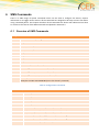
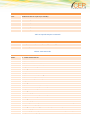
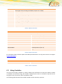
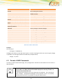
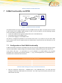
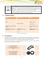
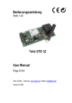
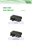
STD32 User Manual Revision 2.0 Important information This user manual contains important information to start up and use the STD32 device. Read it carefully before you start working with the STD32. The warranty will be void should damage occur to the device due to non-compliance with these instructions. We cannot accept any responsibility for any loss resulting from this non-compliant use. We cannot be held responsible for material loss or personal injury that is due to incompetent use or non-compliance with the safety instructions. The warranty will be void in such circumstances. The STD32 contains highly integrated components which can be damaged by electrostatic discharge if the user opens the housing. Please avoid touching components on the board of the STD32 with the exception of the SIM card holder and connections. Safety Instructions When using products which are exposed to electric voltage the valid VDE-regulations have to be observed. Especially VDE 0100, VDE 0550/0551, VDE 0700, VDE 0711 and VDE 0860 are applicable. All wiring work has to be done in a voltage free state only. All cables and wires which are energized and connected to the device, the module, or components have to be checked regularly for any damage to the isolation shielding or fractures in the cables. If the supply cables are visibly damaged the device has to be taken out of operation immediately until the faulty cable has been exchanged. Before putting a device into operation, it has to be clarified, whether this device or module is appropriate for the field of application. In case of doubt ask a specialists or the manufacturer of the device. Please note that we are not responsible for any errors in usage or connection. Therefore we cannot accept any responsibility for consequential loss. Before opening the device always disconnect the mains adapter or make sure that the device is disconnected from the power supply. Components, modules or devices have to be built into a housing before they are put into operation. During installation they should not be connected to any power supply . You should only use tools on components, modules, or devices if they are disconnected from the power supply, and residual electric charge (which may still be stored in some components inside the device) has been discharged. When using components or modules it is necessary to strictly observe the specification given in the corresponding description of these components. If a description for a private end-customer does not clearly state which electric data is valid for a component or a module, how to wire the device, which external components, or additional devices can be connected or which parameters these components are allowed to have, a specialist must be contacted. Devices which operate with greater than 35 Volts have to be connected by a specialist. 2 Before putting the device into operation it should be checked that there is no current leakage on the housing. In case measurements need to be performed with an opened housing, an isolating-transformer has to be integrated for safety reasons. Alternatively the voltage can be supplied by an appropriate power supply which complies with the safety regulations. All wiring work has to be done in a voltage free state only. Table of Contents Important information ...................................................................................................................................................... 2 Safety Instructions ............................................................................................................................................................ 2 1 Introduction .............................................................................................................................................................. 6 2 Operating Conditions ................................................................................................................................................ 7 3 Application Areas ...................................................................................................................................................... 7 4 STD32 Product Overview .......................................................................................................................................... 7 5 Quick Start Up ........................................................................................................................................................... 9 5.1 General preparations ........................................................................................................................................ 9 5.2 Preparing the Device ....................................................................................................................................... 10 5.3 Call-based Configuration ................................................................................................................................. 10 5.4 Quick Configuration Check.............................................................................................................................. 10 6 SMS Commands ...................................................................................................................................................... 11 6.1 Overview of SMS Commands .......................................................................................................................... 11 6.2 Using Variables ................................................................................................................................................ 13 6.3 Format of SMS Commands ............................................................................................................................. 14 6.4 Explanation of the commands ........................................................................................................................ 15 6.5 Examples of SMS Commands .......................................................................................................................... 16 7 E-Mail functionality via GPRS .................................................................................................................................. 17 7.1 Configuration of the E-Mail functionality ....................................................................................................... 17 8 Troubleshooting ...................................................................................................................................................... 18 9 Accessories .............................................................................................................................................................. 18 10 Technical data ..................................................................................................................................................... 20 11 Document history ............................................................................................................................................... 21 4 Overview of Tables Table 1: Allocation of screw terminals .............................................................................................................................. 8 Table 2: Configuration Commands ................................................................................................................................. 11 Table 3: Inputs & Outputs commands ............................................................................................................................ 12 Table 4: CLIP commands ................................................................................................................................................. 12 Table 5: DATA commands ............................................................................................................................................... 13 Table 6: DOTA commands ............................................................................................................................................... 13 Table 7: Misc commands ................................................................................................................................................ 13 Table 8: Variable substitution ......................................................................................................................................... 14 Table 9: Examples of SMS Commands ............................................................................................................................ 17 Table 10: GPRS settings (to set up an Internet connection) ........................................................................................... 17 Table 11: Troubleshooting .............................................................................................................................................. 18 Table 12: STD32 Accessories ........................................................................................................................................... 19 Table 13: Document history ............................................................................................................................................ 21 Overview of Figures Figure 1: Positioning of the connectors on the STD32 ..................................................................................................... 8 Figure 2: E-Mail functionality via GPRS ........................................................................................................................... 17 1 Introduction Thank you very much for purchasing our CEP STD32 telemetry device! The STD32 enables the user to remotely switch ON or OFF electronic devices and to receive alarm messages via SMS. You can switch devices either with an SMS or using a simple voice call. Alarm messages (SMS) can be received with any mobile phone supporting SMS functionality. With the STD32 you can also receive alarm messages by E-Mail. We wish you success in using your new STD32! Please note that this user guide is applicable only for STD32 Units with serial numbers starting with 0834<IMEI> (these can be found on the device’s label). Concerning the user manual This document is meant to help you use the various functions of the device in the most optimal way. Therefore we ask you to please read this manual carefully. If you are in a hurry and want to make yourself familiar with the details of the product later, then please read Section 5 “Quick Start ” first. There you will find all necessary information to put the device into operation. The information in this document has been gathered after thorough inspection but they are not being taken as assurance of end product properties. The written approval of CEP AG is mandatory before you can pass on or reproduce this documentation for this product or the software or use the content. CEP reserves the right to change the data mentioned here without prior notice and does not take any responsibility for technical inaccuracies and/or omissions. This manual has been thoroughly checked; should you nevertheless find an error or want to express criticism or make suggestions, please send an E-Mail to E-Mail: [email protected] Oberhaching, 31. March 2015 © 2015 CEP AG, Oberhaching, Germany This is an example of text for the main body. Style name: Text – Standard 6 2 Operating Conditions Operate the STD32 only with a supply voltage between 7-32V DC and have in mind the polarity! (see picture1) Use a stabilized power supply with minimum 1A output current. (We recommend using only the original CEP power supply). If you use a mains adapter for power supply it has to conform to the VDE regulations. Devices operating at a voltage level > 35V and which are connected to relays must be installed only by professional technicians according to the local regulatory requirements for safety! 3 Loads connected to the device are not allowed to exceed 30 W per relay. The maximum output voltage is 250 V AC for output 1 and 2 The maximum switching current for output 1 and 2 is 5A When installing the device make sure that the supply cable has a sufficient diameter During operation the temperature must be in the range -30° to +75° Celsius. Protect the PCB of the device from humidity, spray water and heat. In case of condensation allow a period of about 2 hours for acclimatisation. Do not operate the device in areas where inflammable gas, vapours, or dust are or could be present. Do not expose the device to heavy vibrations. The unit may only be repaired by a specialist. Only original parts have to be used when repairing the unit. The use of differing spare parts can cause serious material loss or personal injury. No special positioning is required to operate the device. Application Areas The device is designed for the remote switching of devices via the GSM network as well as the remote retrieval of status information of the inputs and the generation of SMS messages or E-Mails after status has changed at the inputs. A different utilization of the device other than the ones described here is not allowed. 4 STD32 Product Overview The STD32 is a telemetry module which is easy to install and simple to use. It can be configured using any GSM mobile phone, SMS capable software, or the CEP STD32 configuration tool (sold separately). With the STD32 you can control two 5A relays and monitor the status of two digital inputs with one or several standard mobile phones. Apart from the STD32 you only need a valid SIM Card from any network provider (GSM850 / 900 / 1800 or 1900 MHz) While using prepaid SIM-cards, always keep aware of the amount of remaining budget left on the card, so that in case of alarms a message still can be transmitted. Figure 1: Positioning of the connectors on the STD32 Outputs Inputs Power Supply Screw 1: Output 1 a Screw 4: Input 1 Screw 8: VIN+ Screw 2: Output 1 b Screw 5: Input 2 Screw 9: GND Screw 3: Output 2 a Screw 6: Not used Screw 4: Output 2 b Screw 7: Common ground for inputs 1 & 2 (GND) Table 1: Allocation of screw terminals Please note the following instructions: Screw terminal “Outputs”: Here, electrical loads are connected to the respective relay. Screw terminal “Inputs”: The inputs are activated as soon as a voltage is applied within the specified range between the terminals (e.g. Input 1 and GND; refer to Section 0, ” 8 Technical data”). Screw terminal “Power Supply”: Power supply is applied on screw 8 (VIN +) and screw 9 (GND). The used terminal blocks are designed for cables with a cross-section of 0.08mm² to 1,3mm² (both single core and multistring). The (FME-Female) connector “Antenna” is used to connect the GSM antenna. Please observe the maximum output voltage of the relays and the maximum input voltage of the inputs! (Refer to Section 2 Operating Conditions). Status LEDs: The STD32 has several LEDs that indicate the operating status: L1 (Green): status of the power supply. It flashes in green when the external power is applied to the device. L2 (Yellow): GSM status. This LED flashes once every 2 seconds for a short moment when the device is logged into the GSM network. L3 (Red): General Status LED. Cyclic flashing 1x every 2 seconds: the device is ready for use. L4 (Green): General Status LED This indicates whether an administrative telephone number is configured or not (see section 5.1). An alternate flashing of the LEDs L3 and L4 indicates that the device has not yet been configured. Switch: A hardware reset of the device is performed if the switch is pressed for more than 7 seconds. 5 Quick Start Up The following section provides step by step instructions to get the STD32 up-and-running without extensive setup. 5.1 General preparations You need an activated SIM card of a GSM network provider. The PIN of this card has to be set to “0000” (4 times zero). As an alternative, you could use the PIN “2468”. To change the PIN you can use a regular mobile phone. Please refer to your mobile phone manufacturer’s user manual for instructions on how to change the PIN. If you use a SIM card with a PIN different from “0000” or “2468” in the STD32, the STD32 will use a “wrong” PIN. After the second attempt to power up the device your SIM card will be blocked. In this case you need to use the “Super-PIN” or “PUK” to assign a new PIN to your card. Please look into the user guide of your mobile phone. There you find how to use the PUK to de-block the SIM card. You can also use a SIM card without a configured PIN. In the following we refer to the “Master Mobile” as the mobile telephone which you want to use to switch the outputs and to configure the STD32 via calls. The “incognito” or “private call” function of the mobile must be deactivated in order to be able to administer the STD32. In other words, the Master Mobile has to transmit the mobile phone number with every call. Please refer to the user guide of your mobile telephone to change this setting. To test the setting you can call a different mobile phone; there your phone number or name should be displayed. 5.2 Preparing the Device Please insert the SIM card into the SIM card holder on the PCB prior to connecting the supply voltage and switching on the STD32. To open the SIM card holder move it sideways and flip it open; insert the card (mind the proper orientation of the card) and close it again. Move the top sideways in the opposite direction to lock the SIM card in place. Now please connect the GSM antenna which is part of the delivery to the proper antenna connector on the STD32 board (see Figure 1). After this step, connect the external power supply using the appropriate screw terminal. Please always observe the proper polarity of the power supply (see Figure 1). 5.3 Call-based Configuration After having connected the power supply and turned on the device for the first time, the General Status LEDs (L3 & L4, see Figure 1) will start blinking alternately. This indicates that the device is in its original factory settings. Shortly after that the GSM LED will be activated. Now the STD32 will automatically attempt to connect to the GSM network. As soon as this is completed, the GSM LED will flash once every 2 seconds. The STD32 is now ready and can be configured. In the next step, call with the Master Mobile the phone number of the SIM card which is inside the STD32. The STD32 will accept the call and cancel it a few seconds later. During this call, a four digit DTMF sequence is sent to the caller and you will hear them on your mobile phone. With this call the STD32 is configured to the Master Mobile. After a successful configuration it will automatically send an SMS with the text “START-UP-ALARM” to the preconfigured telephone number as soon as the power supply is established again. 5.4 Quick Configuration Check To check whether the configuration was successful you can now make the following quick configuration check. Take your Master Mobile and call the telephone number of the SIM-Card inside the STD32. This call should be cancelled by the STD32 and the Relay 1 should switch for one second. Now the basic configuration is done which means that all future events will be sent to the Master Mobile and that Relay 1 can be switched from that mobile phone. To use the additional functions of the STD32 please continue reading chapter 7 “SMS commands” 10 6 SMS Commands There is a wide range of special commands which can be used to configure the device, request information or to trigger certain actions. All the commands are designed to be easy to enter even when using a standard phone. This chapter describes all the commands the device will understand and how to use them. The format of the SMS commands is explained in Section 6.3. 6.1 Overview of SMS Commands Configuration Commands R: reset default factory settings ST? request device status SMS S: 1 - enable startup SMS 0 - disable startup SMS C2: set phone number nr 2 C3: set phone number nr 3 C4: set phone number nr 4 C5: set phone number nr 5 PN: set different password (max 4) E1: set message text for INPUT 1 event (max 64) E2: set message text for INPUT 2 event (max 64) PT: set message text for POWER-UP event (max 64) M1: Set the phone number of the Administrator Phone Example: xxxx M1:+49123456789 (xxxx is the device’s password) Table 2: Configuration Commands Inputs & Outputs commands O1ON turn relay 1 on O1OFF turn relay 1 off O2ON turn relay 2 on O2OFF turn relay 2 off O1:xxxxx defines time period for relay 1 action (in seconds) 0 = infinite O2:xxxxx defines time period for relay 2 action (in seconds) 0 = infinite A1:xxxxx defines delay for relay 1 reply (in seconds) 0 = no message A2:xxxxx defines delay for relay 2 reply (in seconds) 0 = no message I1:xxx debounce time for input 1 (in seconds) Inputs & Outputs commands I2:xxx debounce time for input 2 (in seconds) V1:x 1 - invert input 1 0 - normal input 1 V2:x 1 - invert input 2 0 - normal input 2 Table 3: Inputs & Outputs commands CLIP commands CL: add clip list number, asterisk symbol (*) is also supported CD: remove clip list number Table 4: CLIP commands DATA commands EMAIL: 1 - enable E-Mail feature 0 - disable E-Mail feature default is enabled SMTPIP:XXXXX defines SMTP server IPv4 address example SMTPIP:"smtp.aol.com" max length is 32 SMTPPORT: defines SMTP server PORT example SMTPPORT:2121 value must be a number, in range 0.. default is 25 APN: defines GPRS APN (for E-Mails) example APN:Internet max length is 32 default is Internet APNUSR: defines GPRS USERNAME (for E-Mails) example APNUSR:Patryk max length is 32 default is empty APNPWD: defines GPRS PASSWORD (for E-Mails) example APNPWD:Patryk max length is 32 default is empty SMTPUSR: defines smtp username (used for authentication - this is not APN username!) example SMTPUSR:"p.szymczak" max length is 64 (according to RFC0821, chapter 4.5.3. SIZES) default is empty SMTPPWD: defines smtp password (used for authentication - this is not APN password!) example SMTPPWD:"p.szymczak" 12 DATA commands FROM: TO: BODY: TESTMAIL max length is 64 (according to RFC0821, chapter 4.5.3. SIZES) default is empty defines E-Mail sender example FROM:"[email protected]" max length is 25 default is empty defines up to 5 E-Mail recipients (separated by ";"), each one max 25 characters example TO:"[email protected]" max length of field is 129 [(5*25+1)-1] default is empty General content of the E-Mail which may contain substitutable variables Dispatched to request a test E-Mail Table 5: DATA commands DOTA commands DOTAAPN:Internet.DOTAAPNUSR:"".DOTAAPNPWD:"".DOTAREQ. DOTAUSR: set FTP username (max 16) DOTAPWD: set FTP password (max 16) DOTASERVER: set FTP server IPv4 or domain (max 64) DOTAFILE: set filename (max 64) DOTAAPN: set APN (max 24) DOTAAPNUSR: set APN username (max 12) DOTAAPNPWD: set APN password (max 12) DOTAREQ: trigger DOTA Table 6: DOTA commands For Information about software update with DOTA (Download Over The Air) please contact our Support ([email protected] ) Misc commands VERSION ? request current software version Table 7: Misc commands 6.2 Using Variables You can use text strings “variables” in order to display more information in event texts. When a variable is included in an event text string, the variable is replaced by the value it is intended to represent in the string that is sent to the user, either vian SMS or E-Mail. The following table describes the available variables and the data they represent Variable Description $CALID$ last incoming CLIP number $CNT$ X/Y (where X is sent SMS counter and Y is sent E-MAIL counter) $IN1$, $IN2$, $IN3$, $IN4$, $IN5$ current input value as a string (LOW or HIGH) $OUT1$, $OUT2$, $OUT3$, $OUT4$, $OUT5$ current relay value as a string (ON or OFF) $IN1T$, $IN5T$ $IN4T$, current input value as a integer (0 or 1) $OUT3T$, current relay value as a integer (0 or 1) $IN2T$, $IN3T$, $OUT1T$, $OUT2T$, $OUT4T$, $OUT5T$ $VBATM$ battery voltage in milivolts (integer) $VBAT$ battery voltage in volts (float) $VMAINSM$ mains voltage in milivolts (integer) $VMAINS$ mains voltage in volts (float) $VIN4M input 4 voltage in milivolts (integer) $VIN4$ input 4 voltage in volts (float) $VIN5M$ input 5 voltage in milivolts (integer) $VIN5$ input 5 voltage in volts (float) Table 8: Variable substitution Example: The command E1: Supply = $ VMAINS $ V. configures the device so that with active input 1 it sends a message in which the current supply voltage is specified. This message could then look like this (example value): "Supply = 11,712V". 6.3 Format of SMS Commands In order to avoid unauthorized usage, every configuration command to the STD32 must start with a 4digit password. In the default factory settings, this password consists of the last 4 digits of your device’s IMEI. This IMEI (International Mobile Equipment Identity) number can be found on the back of the unit. If you change this password, you must note that all commands – also reverting to factory settings – presuppose knowledge of this password. If this is not known, resetting the password is only possible by using the USB interface. 14 All commands (except R: and ST?) must end with a full stop “.”! All commands can be sent in one SMS; each command has to be separated from the next by a full stop (see examples). If you need a full stop "." in a parameter as it is for example in an E-Mail address or in some APNsettings, the complete parameter has to be put into inverted commas (“...”) (e.g. "[email protected]"), as otherwise the "." would be seen as the end of the command. Parameters for representing seconds (e.g. command “O1:xxxxx.”) can have 1-5 digits. Valid parameters are e.g. 1 (for 1 second), 90 (for 90 seconds) or 99999 for (99999 seconds). No leading “zeros” have to be added. Example: “O1:110” stands for 110 seconds. Please observe the difference between the figure ‘0’ and the letter ‘O’!. (“O1ON.” Contains twice the letter O; “V1:0.” contains once the figure 0) 6.4 Explanation of the commands Switching outputs via SMS After the STD32 has received an SMS with the text “O1ON.” (Output 1 ON) from the configured mobile phone, the relay 1 switches for one second. With the SMS “O2ON.” relay 2 switches for one second. To get feedback of the actual status of the inputs and outputs just send an SMS with “ST?” Configuration-SMS (Attention: 4-digit keyword is required!) The SMS “R:” sets the STD32 back to the factory settings. Please note that this SMS can be sent from any mobile phone as long as the 4-digit keyword is known. This ensures that the STD32 can still be used even if the original Master Mobile (phone number) is no longer available. You can activate or deactivate the Start-up SMS (START-UP ALARM) with the SMS “S:x.” (x = 1 or 0). AN SMS with the text “O1:xxxxx.” or “O2:xxxxx.” (xxxxx = seconds) configures the switching time of the relays. The STD32 saves these settings so that they are still available after the supply voltage has been restored. If the switching time has been set to 0 by a configuration SMS the corresponding relay switches permanently at every call. If the relay has been active before it will afterwards be inactive and vice versa. In this case an SMS with the text “O1ON.” from the configured mobile phone switches the relay 1 permanently on. AN SMS with “O1OFF.” permanently switches off relay 1. Relay 2 reacts accordingly to SMS messages with “O2ON.” and “O2OFF.”. The SMS “A1:xxx.” or “A2:xxx.” (x = seconds) sets the delay after which a reply SMS is sent after an output has been activated. This can be helpful if you want to switch something on or off and would like to measure the result of this output control with one of the inputs of the STD32. Therefore the new status after the switching of the output is transmitted. If parameter is set to “0” no message will be sent. With an SMS containing the text “I1:xxx.” or “I2:xxx.” (xxx = seconds) you can configure the time the inputs have to be activated before the STD32 sends out an alarm SMS AN SMS with the text “V1:x.” or “V2:x.” (x = 1 or 0) can change the polarity of the inputs. If x=1 an alarm SMS will be sent in case the input is deactivated for the configured Time. The default value is x=0 which means that the STD32 will send an event alarm in case the input has been activated longer than the configured time. Please note that the brackets “<“ and “>“in the following commands are not part of the commands but are included in order to increase the readability of the overview! Four additional alarm numbers (mobile phones) can be defined using C2: - C5: commands. These numbers are allowed to set relay 1 by a call and they are informed vian SMS in case of Start-up or events. These numbers are not allowed to send configuration SMS messages unless they include the password in the SMS. If an alarm number is given in international format, the number must start with ‘+’. (e.g. +491721234567) With the command “PN:<4digit password>.” the password can be changed. The password can include letters and figures but special characters are not allowed. All letters have to be in capital. The texts of the event or start-up SMS can be changed with the commands “E1:<text1>.”, “E2:<text2>.”… and “PT:<startup text>.”. The message length must not exceed 64 characters. Do not use command syntax inside a message text. The ‘.’ is the terminating character of the text. Each new text must be sent in a separate SMS. You can generate an extended clip list of 1000 clip numbers. The numbers stored in the clip list are allowed to switch relay 1 with a phone call. Use “CL:” to generate the clip list and add further phone numbers. With “CD:” you can delete a phone number from the list. Be aware that you cannot read out the clip list (getting SMS messages) because it could by far exceed the size limitation of SMS texts. With the command “TOx:<text>.” (x = 1 to 10, see command list above) an E-Mail address for the particular events is configured. 5 E-Mail Adresses can be configured, divided by <;>. The maximum length of the particular E-Mail addresses is 25 signs. With the command “SUBx:<text>.” (x=1 to 10, see command list above) the subject of the particular E-Mails is configured. The maximum number of sings for the subject is 128 signs. The predefined text is: “STD32 Event x”. The content of the E-Mail is configured with “BODY:<text>.”. The maximum length is 143 signs. The E-Mail sender address (of the STD32) is changed with “FROM:<text>.”. The maximum length is 25 signs. Please note that all commands listed in the section “Configuration SMS” require the 4-digit keyword at the beginning. 6.5 Examples of SMS Commands In the following examples, each command is preceded by a 4-digit password. Here, the password is set to the value "9851", but it must be replaced with your unique password. Task SMS Command Sequence Start-up alarm off, relay 1 on, relay 2 off, time of activation of input 1: 5 sec 9851 S:0.O1ON.O2OFF.I1:5. Switching time of relay 1 = 90 seconds 9851 O1:90. Reset settings to factory settings 9851 R: Configuration of the second alarm number 9851 C2:+491721234567. Deleting a alarm number 9851 C2:"". Configuration of a new password 9851 PN:AB12. Adding a new clip to the extended clip list 9851 CL:+491721234567. Removing the clip from the extended clip list 9851 CD:+491721234567. 16 Table 9: Examples of SMS Commands 7 E-Mail functionality via GPRS Netzbetreiber z.B Vodafone Internet SMTP E-Mail Server z.B. AOL IP Port Benutzername Passwort APN Benutzername Passwort STD32 Figure 2: E-Mail functionality via GPRS The STD32 enables you to get messages not only via SMS but also via E-Mail. You need to have an active E-mail account with an SMTP E-Mail provider in order to use this feature, and the following settings have to be made for the E-Mail service: name of the SMTP server (eg smtp.mailprovider.com or 192.168.234.12) username to log on to the SMTP server password for logging on to the SMTP server The device is configured by default to use the CEP E-mail server. If you wish to use your own E-Mail service, please ensure that it supports plain text authentication. Please also note the information in the next section. 7.1 Configuration of the E-Mail functionality E-Mail functionality should work by default if the user has correctly configured the APN settings and the receiver E-Mail address. SMTP settings are be default already configured using the CEP E-Mail server. If you need a full stop "." in a parameter as it is for example in an E-Mail address, the complete parameter has to be put into inverted commas (“...”) (e.g. "[email protected]"), as otherwise the "." would be seen as the end of the command. GPRS settings (to set up an Internet connection) Name of the APN (Access Point Name) APN:<text>. User name for APN APNUSR:<text>. Password for APN APNPWD:<text>. Table 10: GPRS settings (to set up an Internet connection) With the commands “APN:<text>.”, “APNUSR:<text>.” and “APNPWD:<text>.” you make the basic settings to build up a GPRS (Internet) connection. You need to get the necessary data from your GSM network provider. In most cases it is not necessary to configure any of the SMTP settings as the device come preconfigured for the e-mail server subscribed by CEP, which is a free service for STD32 users. If the user wishes to use another server it must support plain text authentication. CEP does not maintain a list of mail providers the support plain text authentication, this information must come the provider of the mail server. CEP does not maintain own infrastructure for the E-Mail service. Changes in external services may take place at any time and are beyond our control. 8 Troubleshooting Problem Possible Reason Solution Power LED (L1) stays switched off GSM LED (L2) blinks three times cyclically GSM LED (L2) constantly on No supply voltage- Connect power supply PIN is not “0000” or “2468” Change SIM card’s PIN to “0000” or “2468” Connect antenna / Change antenna position STD32 does not react on configuration call (not accepting the call) STD32 does not react to an SMS, or call, although booked to the network Device is already configured System LEDs toggle No configuration call received by STD32 No GSM network available / no antenna connected The mobile phone does not transmit the phone number (“Incognito”) Set back to factory settings or set new administration number Activate the transmission of the phone number in your mobile phone Make configuration call Table 11: Troubleshooting 9 Accessories CEP GmbH offers accessory parts for the STD32 which have been thoroughly tested to work and approved for use with the STD32. Therefore we strongly recommend using only CEP AG accessory wparts. The warranty will be void if you use other than the original CEP accessory parts. Please contact your supplier or CEP GmbH regarding the original accessory parts. The recommended accessory parts mainly consist of the following: GSM – magnetic antenna -Part-Number 12001 FME – female connector and 2,5m cable GSM – roof mount antenna -Part – Number 12006 FME – female connector, 3m cable, waterproof 18 Table 12: STD32 Accessories 10 Technical data GSM: Quad Band EGSM 850/900/1800/1900 MHz Compatible with ETSI GSM Phase 2+ Standard Output power: Class 4 (2W @ 850/900 MHz) Class 1 (1W @ 1800/1900 MHz) Temperature range: -30°C - +75°C Weight approx. 220 grams Dimensions: 150x65x45 mm (l x w x h) Supply voltage: 7-32V Current consumption during normal operation: ~14 mA, peak up to 1A Max. output current Output 1&2: 5A Max. output voltage Output 1&2: 30V DC; 250V AC Max. output current Output 3&4 and 5: 30V DC Max. output voltage Output 3&4 and 5: 30V DC Input voltage (digital inputs) logic 1 (threshold >7V): max 30V logic 0 (threshold <1,5V): min 0V Input voltage (analog inputs) Max (30V) Min (0V) In case of technical problems or questions concerning the STD32, please get in contact with your STD32 reseller. Monday- Friday: Technical Hotline: E-Mail Support: 9 am – 12 am and 1pm – 5 pm +49 (0) 89/ 45 02 92 – 11 [email protected] For all other questions please call: Sales: +49 (0) 89 / 450292-0 20 11 Document history Revision Datum Changes Rev. 1.0 16th Dec 2010 Original file Rev.1.1 14th Jan 2011 Update Rev 1.2 23rd Jan 2011 Added Configuration Tool Rev 1.3 6th June 2011 Minor Corrections Rev 1.4 9th June 2011 Corrected relay voltage mistake Rev 1.5 10th December 2013 Change from Telic to CEP, Complete Update Rev. 2.0 31st March 2015 Content adapted to new hardware Table 13: Document history Imprint These operating instructions are published by CEP AG No reproduction (including translation) is permitted in whole or part e.g. photocopy, microfilming or storage in electronic data processing equipment, without the express written consent of the publisher. The operating instructions reflect the current technical specifications at time of print. We reserve the right to change the technical or physical specifications. © Copyright 2015 by CEP AG CEP AG Raiffeisenallee 12b D-82041 Oberhaching Germany www.cepag.de CEP reserves the right to change, correct and/or improve the content any time and without prior notice without being obliged to do so. No responsibility is taken for the correctness of the information.