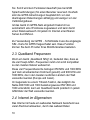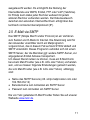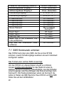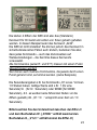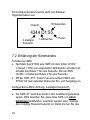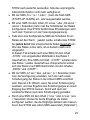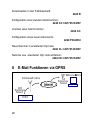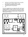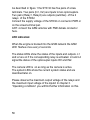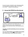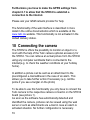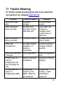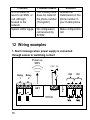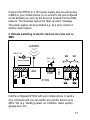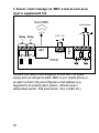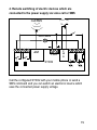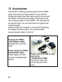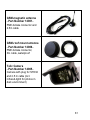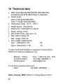
1
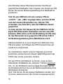
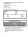
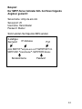
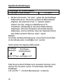
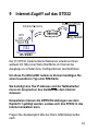
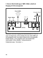
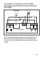
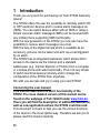
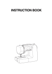
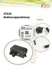
Bedienungsanleitung
Seite 1-42
Telic STD 32
User Manual
Page 43-84
Telic GmbH – Internet: www.telic.de; E-Mail: [email protected]
Version 01/09
1
Einleitung ......................................4
1.1 Achtung, bitte lesen .......................6
2
Erklärung technischer Grundlagen..9
2.1 GSM-Netz im Allgemeinen .............9
2.2 GPRS............................................9
2.3 Quadband Frequenzen ................10
2.4 Internet im Allgemeinen................10
2.5 E-Mail via SMTP..........................11
2.6 Web Server .................................12
2.7 Fixed IP.......................................12
3
Betriebsbedingungen ...................13
4
Bestimmungsgem. Verwendung...14
5
Einführung...................................15
6
Schnellstart-Anleitung ..................17
6.1 Allgemeine Vorbereitungen ..........17
6.2 Vorbereitungen an der Hardware..19
6.3 Konfiguration per Anruf ................19
6.4 Schnelltest der Konfiguration........21
7
Übersicht der SMS Kommandos...21
7.1 SMS Kommando schicken ...........22
7.2 Erklärung der Kommandos...........24
7.3 Beispiele SMS Kommandos .........27
2
8
E-Mail Funktionen via GPRS ....... 28
8.1 Einrichten der E-Mail Funktion ..... 29
9
Internet-Zugriff auf das STD32..... 33
10
Anbindung der Kamera................ 34
11
Fehlerbehandlung ....................... 35
12
Anschlussbeispiele...................... 36
13
Zubehör ...................................... 40
14
Technische Daten und Hotline ..... 42
3
1 Einleitung
Vielen Dank, dass Sie sich für den Kauf eines STD32
Telemetriemoduls aus dem Hause Telic entschieden haben!
Das STD32 bietet nahezu jedem Nutzer die Möglichkeit, aus
der Ferne Verbraucher ein- und auszuschalten und Alarme
übermittelt zu bekommen. Dabei kann die Übertragung von
Schalt- und Alarmmeldungen per SMS über jedes SMS-fähige
Handy oder über einen Sprachanruf erfolgen.
Mit der neuen Generation des STD32 ist es Ihnen ab sofort
zusätzlich möglich, E-Mails als Alarmmeldung zu versenden.
Mit der als Zubehör verfügbaren Digitalkamera können im
Alarmfall sogar Fotos aufgenommen und ebenfalls per E-Mail
verschickt werden.
Der auf dem STD32 implementierte Webserver erlaubt darüber
hinaus den direkten Internet-Zugriff per Standard-Webbrowser
(wie z.B. Internet Explorer oder Firefox) vom PC oder von
Ihrem internetfähigen Handy aus. Somit lassen sich sehr
einfach Verbraucher über das Internet von überall aus schalten
und Konfigurationen des STD32 verändern.
Wir wünschen Ihnen viel Erfolg und viel Freude bei der
Nutzung Ihres neuen STD32!
Zu dieser Anleitung:
Diese Anleitung beschreibt die Grundfunktionen des
STD32. Eine ausführliche Fassung dieser Anleitung finden
Sie auf der Homepage der Telic GmbH unter www.telic.de.
Hier werden auch Funktionserweiterungen und neue
Anwendungen beschrieben, die Ihnen weitere
Einsatzmöglichkeiten mit dem STD32 ermöglichen.
4
Die vorliegende Dokumentation soll Ihnen helfen, die
vielfältigen Funktionen des Geräts optimal zu nutzen. Daher
lesen Sie sich diese Anleitung bitte sorgfältig durch.
Wenn Sie in Eile sind und sich mit den Details des Produkts
später vertraut machen möchten, dann lesen Sie bitte zuerst
Kapitel 6 „Schnellstart Anleitung“.
Dort finden Sie alle wichtigen Informationen, um das Gerät
schnell in Betrieb nehmen zu können.
Alle Angaben in dieser Dokumentation sind nach sorgfältiger
Prüfung zusammengestellt worden, gelten jedoch nicht als
Zusicherung von Produkteigenschaften.
Die Weitergabe und Vervielfältigung der zu diesem Produkt
gehörenden Dokumentation und Software und die Verwendung
ihres Inhalts sind nur mit schriftlicher Erlaubnis der Telic GmbH
gestattet.
Telic behält sich vor, die genannten Daten ohne Ankündigung
zu ändern und übernimmt keine Gewähr für technische
Ungenauigkeiten und/oder Auslassungen.
Sollten Sie trotz sorgfältiger Bearbeitung dieser Anleitung
dennoch einen Fehler finden oder einfach nur Kritik oder
Anregung zu dieser Dokumentation äußern wollen, dann
senden Sie bitte eine E-Mail direkt an
E-Mail: [email protected]
Oberhaching, den 23. Januar 2009
© 2009 Telic GmbH, Oberhaching
5
1.1 Achtung, bitte lesen
Diese Bedienungsanleitung enthält wichtige Hinweise zur
Inbetriebnahme und Handhabung des STD32, bitte lesen Sie
diese aufmerksam, bevor Sie das STD32 in Betrieb nehmen!
Bei Schäden, die durch die Nichtbeachtung der
Bedienungsanleitung entstehen, erlischt der Garantieanspruch!
Für Folgeschäden, die daraus resultieren, übernimmt die Firma
Telic keine Haftung.
Bei Sach- oder Personenschäden, die durch unsachgemäße
Handhabung oder Nichtbeachtung der Sicherheitshinweise
verursacht werden, übernimmt die Firma Telic keine Haftung.
In solchen Fällen erlischt jeder Garantieanspruch.
Derjenige, der eine Baugruppe durch Erweiterung bzw.
Gehäuseeinbau betriebsbereit macht, gilt nach DIN VDE 0869
als Hersteller und ist verpflichtet, bei Weitergabe des Gerätes
alle Begleitpapiere mitzuliefern und auch seinen Namen und
Anschrift anzugeben. Geräte, die aus Baugruppen selbst
zusammengestellt werden sind sicherheitstechnisch wie ein
industrielles Produkt zu betrachten.
Das STD32 ist mit hoch integrierten Bausteinen bestückt.
Diese elektronischen Bauteile sind technologisch bedingt sehr
empfindlich gegen Entladungen statischer Elektrizität.
Bitte berühren Sie das STD32 daher nur an
den Seitenrändern und vermeiden Sie die
Berührung der Pins von Bauelementen auf
der Platine.
6
Während des Betriebs des STD32 können automatisch GSMKurznachrichten (SMS) verschickt bzw. GPRS Verbindungen
aufgebaut werden, wodurch Ihnen Kosten von Ihrem
Mobilfunknetzbetreiber in Rechnung gestellt werden, ähnlich
der Nutzung Ihres Handys.
Sicherheitshinweise
Beim Umgang mit Produkten, die mit elektrischer
Spannung in Berührung kommen, müssen die
gültigen VDE-Vorschriften beachtet werden,
insbesondere VDE 0100, VDE 0550/0551, VDE
0700, VDE 0711 und VDE 0860.
Alle Verdrahtungsarbeiten dürfen nur im spannungslosen
Zustand ausgeführt werden.
Spannungsführende Kabel oder Leitungen, mit denen das
Gerät, das Bauteil oder die Baugruppe verbunden ist,
müssen stets auf Isolationsfehler oder Bruchstellen
untersucht werden. Bei Feststellen eines Fehlers in der
Zuleitung muss das Gerät unverzüglich aus dem Betrieb
genommen werden, bis die defekte Leitung ausgewechselt
worden ist.
Es ist vor der Inbetriebnahme eines Gerätes generell zu
prüfen, ob dieses Gerät oder Baugruppe grundsätzlich für
den Anwendungsfall, für den es verwendet werden soll,
geeignet ist! Im Zweifelsfall sind unbedingt Rückfragen bei
Fachleuten, Sachverständigen oder den Herstellern der
verwendeten Baugruppen notwendig!
Bitte beachten Sie, dass Bedien- und Anschlussfehler
außerhalb unseres Einflussbereiches liegen.
7
Verständlicherweise können wir für Schäden, die daraus
entstehen keinerlei Haftung übernehmen.
Vor dem Öffnen eines Gerätes stets den Netzstecker
ziehen oder sicherstellen, dass das Gerät stromlos ist.
Bauteile, Baugruppen oder Geräte dürfen nur in Betrieb
genommen werden, wenn sie vorher berührungssicher in
ein Gehäuse eingebaut wurden. Während des Einbaus
müssen sie stromlos sein.
Werkzeuge dürfen an Geräten, Bauteilen oder Baugruppen
nur benutzt werden, wenn sichergestellt ist, dass die Geräte
von der Versorgungsspannung getrennt sind und
elektrische Ladungen, die in den im Gerät befindlichen
Bauteilen gespeichert sind, vorher entladen wurden.
Bei Einsatz von Bauelementen oder Baugruppen muss
stets auf die strikte Einhaltung, der in der zugehörigen
Beschreibung genannten Kenndaten für elektrische Größen
hingewiesen werden.
Wenn aus einer vorliegenden Beschreibung für den
nichtgewerblichen Endverbraucher nicht eindeutig
hervorgeht, welche elektrischen Kennwerte für ein Bauteil
oder eine Baugruppe gelten, wie eine externe Beschaltung
durchzuführen ist oder welche externen Bauteile oder
Zusatzgeräte angeschlossen werden dürfen und welche
Anschlusswerte diese externen Komponenten haben
dürfen, so muss stets ein Fachmann um Auskunft ersucht
werden.
Geräte, die an einer Spannung > 35 Volt betrieben werden,
dürfen nur vom Fachmann angeschlossen werden.
Die Inbetriebnahme darf grundsätzlich nur erfolgen, wenn
die Schaltung absolut berührungssicher in ein Gehäuse
eingebaut ist.
8
Sind Messungen am geöffneten Gehäuse unumgänglich, so
muss aus Sicherheitsgründen ein Trenntrafo
zwischengeschaltet werden, oder, wie bereits erwähnt, die
Spannung über ein geeignetes Netzteil, (das den
Sicherheitsbestimmungen entspricht) zugeführt werden.
2 Erklärung technischer Grundlagen
2.1 GSM-Netz im Allgemeinen
Das GSM Netz (Global System for Mobile Communications) ist
ein Standard für volldigitale Mobilfunknetze. GSM wurde mit
dem Ziel geschaffen, ein mobiles Telefonsystem anzubieten,
das Teilnehmern eine europaweite Mobilität erlaubt und mit
ISDN oder herkömmlichen analogen Telefonnetzen kompatible
Sprachdienste anbietet.
GSM wurde ursprünglich für Telefongespräche, für die
Versendung von SMS (Kurznachrichten) und für die
Datenübertragung mit konstanter Datenrate konzipiert. Mit dem
Erfolg des Internets begann jedoch ein Umdenken, die so
genannte „Evolution von GSM“, bei der das GSM Netz komplett
abwärtskompatibel mit Möglichkeiten zur paketorientierten
Datenübertragung (z.B via GPRS) erweitert wurde.
2.2 GPRS
Bei GPRS (General Packet Radio Service) handelt es sich um
einen paketorientierten Übertragungsdienst, der im Bereich des
Mobilfunks eingesetzt und von so gut wie allen
Mobilfunknetzen unterstützt wird.
Hierbei besteht nur virtuell eine dauerhafte Verbindung zur
Gegenstelle. Erst wenn wirklich Daten übertragen werden, wird
der Funkraum besetzt, ansonsten ist er für andere Benutzer
9
frei. Somit wird kein Funkkanal dauerhaft (wie bei GSM
Sprachverbindungen) für einen Benutzer reserviert. Deshalb
sind die GPRS-Abrechnungen hauptsächlich von den
übertragenen Datenmengen abhängig und weniger von der
Verbindungsdauer.
Ist das Gerät im GPRS-Netz eingebucht bekommt es
automatisch eine IP-Adresse zugewiesen und kann damit
einen Datenaustausch mit jedem im Internet erreichbaren
Server durchführen.
Zur Verwendung der GPRS - Schnittstelle muss die eingelegte
SIM - Karte für GPRS freigeschaltet sein. Diese Funktion
können Sie beim Provider Ihres Mobilfunknetzes bestellen.
2.3 Quadband Frequenzen
Wenn ein Gerät „Quadband fähig“ ist, bedeutet dies, dass es
die vier Haupt-GSM –Frequenzen nutzt und somit kompatibel
zu den meisten Netzen weltweit ist.
Diese vier Frequenzbereiche betragen 850 MHz und 1900 MHz
(auf dem amerikanischen Kontinent genutzt) und 900 MHz und
1800 MHz, die in den meisten restlichen Ländern der Welt
verwendet werden (Europa und Asien).
Im Gegensatz zu einem Triband-Telefon, das lediglich die
Netze 900/1800 und 1900 beziehungsweise 850/1800 und
1900 unterstützt, kann ein Quadband Gerät praktisch in jedem
GSM-Netz der Welt verwendet werden.
2.4 Internet im Allgemeinen
Das Internet ist heute ein weltweites Netzwerk bestehend aus
vielen Rechnernetzwerken, durch das weltweit Daten
10
ausgetauscht werden. Es ermöglicht die Nutzung der
Internetdienste wie WWW, E-Mail, FTP oder VoIP (Telefonie).
Im Prinzip kann dabei jeder Rechner weltweit mit jedem
anderen Rechner verbunden werden. Der Datenaustausch
zwischen den einzelnen Internet-Rechnern erfolgt über das
technisch normierte Internetprotokoll (IP).
2.5 E-Mail via SMTP
Das SMTP (Simple Mail Transfer Protocol) ist ein Verfahren
zum Senden von E-Mails im Internet. Die Abwicklung wird für
den Anwender unsichtbar durch ein Mailprogramm
vorgenommen, das in diesem Fall auf dem STD32 abläuft und
SMTP unterstützt. Dieses Programm verbindet sich mit einem
SMTP-Server, der die Mail über ggf. weitere SMTP-Server, zur
angegebenen E-Mail Adresse transportiert.
Um diesen Dienst nutzen zu können, muss ein E-Mail Konto
bei einem Mail-Provider (wie z.B. AOL oder Yahoo) vorhanden
sein, und es müssen folgende Einstellungen gemacht werden,
die vom Mail-Provider (wie z.B. AOL oder Yahoo) abhängig
sind:
Name des SMTP Servers (z.B. smtp.mailprovider.com oder
192.168.234.12)
Benutzername zum Anmelden am SMTP Server
Passwort zum Anmelden am SMTP Server
Die von Telic getesteten E-Mail Provider finden Sie auf unserer
Webseite www.telic.de.
11
Welche Einstellungen am STD32 vorgenommen werden
müssen, um diesen Dienst zu nutzen erfahren Sie unter
Abschnitt 8.
2.6 Web Server
Ein Webserver ist ein Programm, das auf einem Gerät läuft,
dem so genannten Server, um Daten und Dokumente an
Clients (z.B. Standard-Webbrowser wie der Internet Explorer
oder Firefox) zu übertragen. Webserver werden überwiegend
als WWW-Dienst im Internet eingesetzt. Die Daten und
Dokumente können von jedem Computer der mit dem Internet
verbunden ist weltweit abgerufen und angezeigt werden.
Ein solcher Webserver ist auch auf dem STD32 implementiert.
Zur Nutzung dieser Funktion müssen Sie einige
Besonderheiten beachten. Näheres hierzu finden Sie unter
Kapitel „9. Internet-Zugriff auf das STD32“.
2.7 Fixed IP
IP-Adressen werden in Computernetzen, die auf dem
Internetprotokoll (IP) basieren, verwendet, um Daten von ihrem
Absender zum vorgesehenen Empfänger transportieren zu
können. Ein Beispiel derartiger Computernetze ist das Internet.
Um einen Webserver ansprechen zu können muss dessen IPAdresse bekannt sein, damit z.B. der Webbrowser Daten von
diesem laden und anzeigen kann. Deshalb werden für Server
meist nur feste IP-Adressen verwendet (Fixed IP).
Die bekannteste Notation der heute geläufigen IP-Adressen
besteht aus vier Zahlen, die jeweils zwischen 0 und 255 liegen
12
und mit einem Punkt getrennt werden, beispielsweise
127.0.0.1.
Um den Webserver auf dem STD32 nutzen zu können muss
der Provider Ihres Mobilfunknetzes dem Gerät eine feste IPAdresse zuweisen und einen Verbindungsaufbau aus dem
Internet zulassen. Diese Funktion ist meist nur auf Anfrage
oder bei speziellen GSM-Netzwerkanbietern erhältlich.
3 Betriebsbedingungen
Betreiben Sie das STD32 nur mit einer Betriebsspannung
zwischen 5-32V DC (Gleichstrom) und beachten Sie die
Polarität! (siehe Abb.1). Es ist ein stabilisiertes Netzteil mit
mindestens 1A Ausgangsstrom zu verwenden (wir raten
Ihnen dringend das Telic Original-Netzteil zu verwenden).
Verwenden Sie ein Netzgerät als Spannungsquelle, so
muss dies unbedingt den VDE-Vorschriften entsprechen!
Bei Geräten mit einer Betriebsspannung >35V, die an
einem der Relais angeschlossen sind, darf die Endmontage
nur vom Fachmann unter Einhaltung der VDEBestimmungen vorgenommen werden!
An der Baugruppe angeschlossene Verbraucher dürfen
eine Anschlussleistung von max. 1000W pro Relais nicht
überschreiten.
Die maximale Schaltspannung beträgt 250V AC
(Wechselstrom)
Der durch die Leiterbahnbreite bedingte maximale
Schaltstrom (pro Relais) beträgt 6A.
Bei der Installation des Gerätes ist auf ausreichenden
Kabelquerschnitt der Anschlussleitungen zu achten.
13
Die zulässige Umgebungstemperatur darf während des
Betriebs -20°C nicht unter- und 55°C nicht überschreiten.
Das Gerät ist zum Betrieb in trockenen und sauberen
Räumen bestimmt.
Schützen Sie das Gerät vor Feuchtigkeit, Spritzwasser und
Hitzeeinwirkung.
Bei Bildung von Kondenswasser muss eine
Akklimatisierungszeit von bis zu 2 Stunden abgewartet
werden.
Betreiben Sie das Gerät nicht in einer Umgebung in welcher
brennbare Gase, Dämpfe oder Staub vorhanden sind oder
vorhanden sein könnten.
Setzen Sie das Gerät keinen starken Vibrationen aus.
Eine Reparatur des Geräts darf nur vom Fachmann
vorgenommen werden.
Falls das Gerät repariert werden muss, dürfen
ausschließlich Original-Ersatzteile verwendet werden. Die
Verwendung abweichender Ersatzteile kann zu ernsthaften
Sach- und Personenschäden führen.
Das Gerät ist von Blumenvasen, Badewannen,
Waschtischen, Flüssigkeiten usw. fernzuhalten.
Die Betriebslage des Gerätes ist beliebig.
4 Bestimmungsgem. Verwendung
Der bestimmungsgemäße Einsatz des STD32 ist das
ferngesteuerte Ein- und Ausschalten von Geräten über das
GSM Netz bzw. das Internet, sowie die Fernabfrage der
Zustände der Eingänge und die Generierung von SMS
Nachrichten bzw. E-Mails nach einer Änderung der Zustände
der Eingänge. Ein anderer Einsatz als der vorgegebene ist
nicht zulässig.
14
5 Einführung
Das STD32 ist ein einfach zu installierendes und zu
bedienendes Telemetriemodul.
Mit dem STD32 können über ein oder mehrere herkömmliche
Mobiltelefone zwei Relais geschaltet und der Zustand zweier
digitaler Eingänge überwacht werden.
Außer dem STD32 benötigen Sie nur noch eine aktivierte SIMKarte eines beliebigen Netzbetreibers (z.B.: D1, Vodafone D2,
E-Plus, O2 (Germany)).
Bei Verwendung von Prepaid-SIM-Karten muss sichergestellt
sein, dass das Guthaben immer ausreicht, um auch im
Alarmfall eine Nachricht zu versenden.
Typische Anwendungen sind:
Schalten von (Garagen-) Türöffnern
Beleuchtungen und Alarmanlagen sowie die Erzeugung von
Alarmmeldungen (Alarm-SMS bzw. Alarm E-Mail)
Abfrage von Türsensoren, Bewegungsmeldern,
Füllstandssensoren
etc
Sie können beispielsweise per Anruf Ihr Garagentor öffnen
oder sich eine Meldung (per SMS oder E-Mail) senden lassen,
wenn Ihre Haus-Alarmanlage auslöst. In Verbindung mit der
Telic Kamera können Sie sich auch per E-Mail ein Foto
zuschicken lassen, wenn ein angeschlossener
Bewegungsmelder auslöst.
15
Relais Relais
1
2
IN2
ANT
PWR
IN1
P
W
R
STD32
Relais1/2 IN2 IN1
L1 L2 L3 L4
GSM
Modul
K
A
Kamera GSM M
LED LED E
R
A
Status LEDs
System LEDs
Abb. 1
Wie in Abb. 1 dargestellt, verfügt das STD32 über fünf
Schraubklemmenpaare. Zwei Paare (In1, In2) sind die
Eingänge zu zwei Optokopplern. Zwei Paare (Relais1, Relais2)
sind die Ausgänge (Schalter) der 2 Relais auf dem STD32.
An der Anschlussbuchse PWR bzw. am fünften
Schraubklemmenpaar wird die Spannungsversorgung des
STD32 angeschlossen.
Am Anschluss ANT wird die GSM Antenne eingeschraubt (Typ
FME-Female).
16
LED Anzeigen:
Wenn das Modul im GSM Netz eingebucht ist, blinkt die GSM
LED etwa alle 2 Sekunden einmal kurz auf.
Die Status LEDs signalisieren den Zustand der Ein- und
Ausgänge.
L1 und L2 leuchten falls das entsprechende Relais aktiviert ist.
L3 und L4 signalisieren den Zustand der Optokoppler-Eingänge
IN1 und IN2.
Die Kamera LED leuchtet, solange die Kamera aktiviert ist.
Die System LEDs dienen der Visualisierung von
Systemzuständen und werden weiter unten beschrieben.
Bitte beachten Sie den maximalen Schaltstrom der Relais und
den maximalen Eingangsstrom und -spannung der
Optokoppler! Im Kapitel „3. Betriebsbedingungen“ finden Sie
weitere Information hierzu!
6 Schnellstart-Anleitung
Im folgenden Abschnitt wird Schritt für Schritt darauf
eingegangen, wie Sie, ohne lange Vorbereitungszeit, das
STD32 administrieren können.
6.1 Allgemeine Vorbereitungen
Zur Inbetriebnahme des STD32 benötigen Sie eine
freigeschaltete SIM Karte eines GSM Netzbetreibers, bei der
die PIN auf „0000“ (vier mal die Null) gesetzt worden ist.
Alternativ hierzu kann auch die PIN „2468“ verwendet werden.
17
Zum Einstellen dieses PIN-Codes benutzen Sie bitte ein
gewöhnliches Mobiltelefon. Das Vorgehen zum Ändern der PIN
können Sie aus der Bedienungsanleitung Ihres Mobiltelefons
entnehmen..
Falls Sie eine SIM Karte mit einer anderen PIN als
„0000“ oder „2468“ eingelegt haben, wird das STD32
nach dem zweiten Einschalten eine „falsche“ PIN
verwenden, was dazu führt, dass Ihre SIM Karte danach
gesperrt ist.
In einem solchen Fall müssen Sie Ihre SIM Karte mit der
Super-PIN (PUK) wieder freischalten und eine neue PIN
zuweisen. Bitte sehen sie für die Einstellung der PIN, bzw.
für das Rücksetzen einer gesperrten PIN mit der PUK in
der Bedienungsanleitung Ihres Mobiltelefons nach.
Selbstverständlich ist es auch möglich eine SIM-Karte ohne
PIN einzusetzen; die Software des STD32 erkennt dies und
verhält sich entsprechend.
Als „Administrator-Telefon“ wird im Folgenden das Handy
bezeichnet, welches Sie zum Steuern und Konfigurieren des
STD32 über Anrufe verwenden möchten.
Um das STD32 administrieren zu können, muss an Ihrem
Administrator Mobiltelefon die „Inkognito“ Funktion deaktiviert
sein, d.h. die Mobiltelefonnummer muss übertragen werden.
Die Einstellung können Sie aus der Bedienungsanleitung Ihres
Mobiltelefons entnehmen.
(Zum Test können Sie ein anderes Mobiltelefon anrufen, dort
muss Ihre Telefonnummer oder Ihr Name angezeigt werden)
18
6.2 Vorbereitungen an der Hardware
Vor dem Anlegen der Versorgungsspannung legen Sie bitte die
SIM-Karte in den SIM-Karten-Halter auf der Rückseite des
STD32 ein. Verschieben Sie hierfür den Deckel des SIMKarten-Halters ein wenig und klappen Sie ihn vorsichtig auf.
Schieben Sie die SIM-Karte in den Deckel, klappen Sie ihn zu
und arretieren Sie ihn durch Verschieben.
Bitte beachten Sie die Orientierung der SIM-Karte,
insbesondere die Lage der abgeschrägten Ecke.
Anschließend schrauben Sie bitte die mitgelieferte GSMAntenne in die auf dem STD32 dafür vorgesehene Buchse.
Danach stellen Sie die Verbindung zur Versorgungsspannung
(entweder über den Klinkenstecker oder Schraubklemme,
jedoch niemals beide zusammen) her.
Bitte beachten Sie dringend die Polung (s. Abb.1) und ob
Ihnen ein geeignetes Netzteil (s. Betriebsbedingungen) zur
Verfügung steht.
6.3 Konfiguration per Anruf
Nachdem Sie die Versorgungsspannung angelegt haben fängt
die grüne System LED für ca. 5 Sekunden an zu
leuchten(System Start), kurz danach leuchtet die GSM LED
dauerhaft.. Das STD32 wird nun automatisch versuchen, sich
in das GSM Netz einzubuchen. Sobald es in das GSM Netz
eingebucht ist, blinkt die GSM-LED etwa einmal alle 2
Sekunden.
Sobald die rote und die grüne System-LED abwechselnd
blinken (das ist das Zeichen, dass das STD32 auf eine
19
Konfiguration wartet) ist das STD32 betriebsbereit und kann
konfiguriert werden.
Rufen Sie dann mit dem Administrator Mobiltelefon die
Rufnummer der SIM Karte im STD32 an. Der Anruf wird
automatisch vom STD32 angenommen und wenige Sekunden
danach wieder beendet. Zur Kontrolle werden mittels DTMFSequenzen vier unterschiedliche Signaltöne gesendet! Diese
können Sie bei diesem Anruf auf Ihrem Mobiltelefon hören.
Durch diesen Anruf wird das STD32 auf das entsprechende
Mobiltelefon eingestellt, es „merkt“ sich Ihre Rufnummer, die
beim Anruf übertragen wird.
Bitte beachten Sie:
Wenn das STD32 wie im Auslieferungszustand ist, so zeigt es
dies durch abwechselndes Blinken der roten und grünen
System LED an. Ab diesem Zeitpunkt haben Sie 3 Minuten
Zeit, das STD32 zu administrieren. Nach Ablauf der 3 Minuten
(ohne dazwischen liegenden Konfigurationsanruf) schaltet sich
das STD32 selbst ab.
Ein erneutes Anlegen der Versorgungsspannung schaltet das
STD32 wieder ein, und es erwartet wieder die Konfiguration
Wird nach einer erfolgreichen Konfiguration das STD32 z.B.
durch einen Stromausfall von der Betriebsspannung getrennt,
sendet das STD32 bei Wiederkehr der Versorgungsspannung
automatisch eine SMS mit dem Inhalt „START-UP ALARM“ an
die eingestellte Telefonnummer.
20
6.4 Schnelltest der Konfiguration
Um überprüfen zu können ob die Konfiguration vollständig
funktioniert hat, können sie nun anschließend einen Schnelltest
durchführen.
Hierzu rufen Sie bitte nochmals mit dem Administrator-Telefon
die Rufnummer der SIM-Karte im STD32 an. Nun sollte
schließlich der Anruf abgewiesen werden und das Relais 1
sollte für eine Sekunde (zu erkennen an der LED L1) schalten.
Nun ist die „Grund-Konfiguration“ abgeschlossen, d.h. alle
zukünftigen Ereignisse werden an das AdministratorMobiltelefon gemeldet und das Relais 1 kann per Anruf von
diesem geschaltet werden.
Um die weiteren Funktionen des STD32 nutzen zu können,
lesen Sie bitte Kapitel 7 Übersicht SMS Kommandos.
7 Übersicht der SMS Kommandos
Auf Fabrikeinstellungen
zurücksetzen
Status anfordern
Start SMS ein/aus
Relais 1 ein
Relais 1 aus
Relais 2 ein
Relais 2 aus
Schaltdauer Relais 1
Schaltdauer Relais 2
Pause vor Rückmeldung (Relais 1)
R:
ST?
S:1. / S:0.
O1ON.
O1OFF.
O2ON.
O2OFF.
O1:xxxxx. (Sekunden)
O2:xxxxx. (Sekunden)
A1:xxx. (Sekunden)
21
Pause vor Rückmeldung (Relais 2)
Aktivierungsdauer Eingang 1
Aktivierungsdauer Eingang 2
Invertierung Eingang 1
A2:xxx. (Sekunden)
I1:xxx. (Sekunden)
I2:xxx. (Sekunden)
V1:x. (x= 1/0 )
Invertierung Eingang 2
2. Alarmnummer
3. Alarmnummer
4. Alarmnummer
5. Alarmnummer
Neues Passwort
Event Text 1
Event Text 2
Start Up Text
Neue Clip in die Erweiterte Clip
Liste aufnehmen
Clip aus der erweiterten Liste
entfernen
V2:x. (x= 1/0 )
C2:<nummer>.
C3:<nummer>.
C4:<nummer>.
C5:<nummer>.
PN:<4-stelliges
Kennwort>.
E1:<text>.
E2:<text>.
PT:<text>.
CL:<nummer>.
CD:<nummer>.
7.1 SMS Kommando schicken
Das STD32 kann über eine SMS, die Sie an das STD32
schicken, sowohl Schaltvorgänge auslösen als auch individuell
konfiguriert werden.
Das Format einer solchen SMS ist wie folgt:
Um das STD32 vor unberechtigtem Zugriff zu schützen,
müssen Konfigurationsbefehle an das Gerät mit einem 4stelligen Kennwort beginnen (Steuerbefehle, wie das Schalten
eines Ausgangs oder das Abfragen des Status benötigen kein
Kennwort!). Die Werkseinstellungen sehen als Kennwort die
letzten 4 Stellen der IMEI Nummer Ihres STD32 vor! Ihre IMEI
finden Sie auf dem GSM-Modul:
22
Die letzten 4 Ziffern der IMEI sind also das (Standard-)
Kennwort für Ihr Gerät und sollten von Ihnen geheim gehalten
werden. In diesem Beispiel lautet das Kennwort „4244“.
Die IMEI ist nicht änderbar! Sie können jedoch das Kennwort in
sicherheitsrelevanten Fällen auch ändern, bedenken Sie aber,
dass jedes Kommando – auch das Zurücksetzen auf
Werkseinstellungen – die Kenntnis dieses Kennworts
voraussetzt.
Alle Kommandos (außer R: und ST?) müssen mit einem Punkt
abgeschlossen werden!
Sie können auch mehrere Kommandos, die jeweils durch einen
Punkt getrennt sind, auf einmal senden. (siehe Beispiele).
Die Sekundenangaben z.B. bei Kommando „O1:xxxxx.“ können
1-5 Stellen haben. Gültige Werte sind z.B.: 1 (für eine
Sekunde) 90 (für 90 Sekunden) oder 99999 (für 99999
Sekunden), d.h. es werden keine führenden Nullen vor die
Ziffern gestellt (z.B. „O1:110.“ entspricht einer Zeit von 110
Sekunden).
Bitte beachten Sie den Unterschied zwischen der Ziffer 0
und dem Buchstaben O! („O1ON.“ enthält zweimal den
Buchstaben O, „V1:0.“ enthält einmal die Ziffer 0)
23
Ein Konfigurationskommando sieht zum Beispiel
folgendermaßen aus:
Output1
55 Sekunden
4244 O1:55.
4-stelliges
Kennwort
Leerzeichen
Punkt
7.2 Erklärung der Kommandos
Schalten per SMS
Nachdem das STD32 eine SMS mit dem Inhalt „O1ON.“
(=Output 1 ON) vom eingestellten Mobiltelefon erhalten hat,
schaltet das Relais 1 für eine Sekunde. Bei der SMS
„O2ON.“ schaltet das Relais 2 für eine Sekunde.
Mit der SMS „ST?“ fordert man eine Antwort-SMS vom
STD32 mit dem aktuellen Status der Ein- und Ausgänge an.
Konfigurations-SMS (Achtung, 4-stelliges Kennwort!)
Die SMS „R:“ setzt das Gerät in den Auslieferungszustand
zurück. Bitte beachten Sie, dass diese SMS von jedem
beliebigen Mobiltelefon verschickt werden kann, solange
das 4-stellige Passwort bekannt ist. Damit können Sie das
24
STD32 auch weiterhin verwenden, falls das ursprüngliche
Administratortelefon nicht mehr verfügbar ist.
Mit der SMS „S:x.“ (x = 1 oder 0) kann die Start-SMS
(START-UP ALARM) ein- oder ausgeschaltet werden.
Mit einer SMS mit dem Inhalt „O1:xxxxx.“ oder „O2:xxxxx.“
(xxxxx = Sekunden) kann man die Schaltzeiten der Relais
konfigurieren. Das STD32 behält diese Einstellungen auch
nach dem Trennen von der Versorgungsspannung.
Falls über eine Konfigurations-SMS die Schaltzeit für ein
Relais auf den Wert 0 gesetzt wurde, schaltet das STD32
bei jedem Anruf das entsprechende Relais dauerhaft um.
War das Relais vorher aktiv, ist es danach inaktiv und
umgekehrt.
In diesem Fall schaltet auch eine SMS mit dem Inhalt
„O1ON.“ vom eingestellten Mobiltelefon das Relais 1
dauerhaft ein. Eine SMS mit Inhalt „O1OFF.“ schaltet dann
das Relais 1 wieder dauerhaft aus. Entsprechend verhält
sich das Relais 2 auf SMS Nachrichten mit den Inhalten
„O2ON.“ und „O2OFF.“.
Mit der SMS „A1:xxx.“ bzw. „A2:xxx.“ (x = Sekunden) kann
man die Verzögerung einstellen, nach der nach einem
Schaltvorgang der Status in der Antwort-SMS verschickt
wird. Dies ist z.B. hilfreich, wenn Sie einen Schaltvorgang
auslösen, und das Ergebnis des Schaltvorganges an einem
Eingang des STD32 messen. Somit wird dann der
veränderte Status nach dem Schaltvorgang gemeldet.
Durch eine SMS mit dem Inhalt „I1:xxx.“ oder „I2:xxx.“ (xxx
= Sekunden) können für beide Eingänge die Zeiten
konfiguriert werden, die die Eingänge aktiviert sein müssen,
bevor das STD32 eine Alarm-SMS aussendet („Entprellen“).
25
Durch eine SMS mit dem Inhalt „V1:x.“ oder „V2:x.“ (x=1
oder 0), können Sie die Reaktion der Eingänge des STD32
invertieren. Bei x=1 meldet das STD32 einen Event-Alarm,
sobald der Eingang länger als die konfigurierte Zeit nicht
aktiviert ist. Die Defaulteinstellung ist x=0, d.h. das STD32
sendet einen Event-Alarm sobald der Eingang länger als die
konfigurierte Zeit aktiviert ist.
Bitte beachten Sie, dass in den folgenden Kommandos die
Klammern „<“ und „>“ nicht Bestandteil des Kommandos sind,
sondern ausschließlich zur besseren Übersicht dienen!
Sie können bis zu vier weitere Alarmnummern
(=Mobiltelefone) (z.B für Alarmnummer 2: „C2:<nummer>.“)
definieren, an die auch Start- und Event-SMS versendet
werden. Diese Rufnummern dürfen ebenfalls das Relais 1
per Anruf schalten, können aber keine Konfiguration oder
sonstige Aktionen per SMS ausführen (C2:–C5:).
Wenn die Alarmnummern in internationalem Format
eingegeben werden, müssen sie mit einem ‚+’ beginnen. (z.B.
+491721234567)
Das Kommando „PN:<4stelliges Kennwort>.“ verändert das
Kennwort. Das Kennwort darf aus 4 beliebigen Zahlen oder
Buchstabenkombinationen bestehen, Sonderzeichen sind
nicht erlaubt. Buchstaben innerhalb des Kennworts sind
immer groß zu schreiben. Im Auslieferungszustand ist das
Kennwort die letzten 4 Ziffern der IMEI, siehe Kapitel „SMS
Kommando“
Die Texte von Start- und Event-SMS können mit den
Kommandos E1:<text1>., E2:<text2>. und PT:<startup26
text>. geändert werden. Innerhalb der Texte darf kein
Konfigurations-SMS-Kommando verwendet werden, der
abschließende Punkt beendet den Text. Pro Textmeldung
sind maximal 64 Zeichen erlaubt. Jeder einzelne
Texteintrag muss in einer separaten SMS erfolgen.
Sie können bis zu fünfhundert weitere Rufnummern dazu
autorisieren, das Relais 1 per Anruf zu schalten. Dazu
müssen Sie mit dem Kommando „CL:<nummer>.“ die
„erweiterte Clip“ Liste anlegen bzw. Rufnummern in diese
CLIP-Liste eintragen. Sie können mit „CD:<nummer>.“ auch
wieder Rufnummern aus dieser Liste löschen. Sie können
sich jedoch besagte Clip-Liste nicht anzeigen bzw. via SMS
schicken lassen, da sie den Rahmen einer normalen SMS
um ein Vielfaches „sprengen“ würde.
Bitte beachten Sie, dass alle Kommandos, die unter Punkt
„Konfigurations-SMS“ aufgeführt sind zwingend mit dem 4stelligen Kennwort beginnen müssen.
7.3 Beispiele SMS Kommandos
Bitte beachten Sie, dass für diese Beispiele das 4-stellige
Kennwort 4244 gewählt wurde. Anstatt diesem Kennwort
müssen Sie das 4-stellige Kennwort Ihres STD32
verwenden!
Startmeldung aus, Relais 1 an, Relais 2 aus, Aktivierungsdauer
Eingang 1: 5 Sek.:
4244 S:0.O1ON.O2OFF.I1:5.
Schaltdauer von Relais 1 auf 90 Sekunden:
4244 O1:90.
27
Zurücksetzen in den Fabrikzustand:
4244 R:
Konfiguration einer zweiten Alarmnummer:
4244 C2:+491721234567.
Löschen einer Alarmnummer
Konfiguration eines neuen Kennworts:
4244 C2:.
4244 PN:AB12.
Neue Nummer in erweiterter Clip Liste:
4244 CL:+491721234567.
Nummer aus erweiterter Clip Liste entfernen:
4244 CD:+491721234567.
8 E-Mail Funktionen via GPRS
28
Das STD32 bietet Ihnen die Möglichkeit, neben einer
Benachrichtigung per SMS auch eine Benachrichtigung per EMail zu erhalten.
8.1 Einrichten der E-Mail Funktion
Wird in einem Parameter ein "." benötigt, wie z.B. in einer
E-Mail Adresse, muss dieser Parameter insgesamt in
Anführungszeichen ("...") gesetzt werden (z.B
"[email protected]"), da der "." ansonsten als Ende des
Kommandos angesehen werden würde.
Desweiteren beachten Sie bitte, dass Sie für
Konfigurations- SMS unbedingt das 4-stellige Kennwort
am Anfang der SMS mit senden müssen.
Um die E-Mail Funktionalität nutzen zu können müssen
folgende Parameter eingestellt werden.
GPRS-Einstellungen
(um eine Internetverbindung herzustellen)
Name des APN (Access Point Name)
APN:<text>.
Benutzername für APN
APNUSR:<text>.
Passwort für APN
APNPWD:<text>.
Mit den Kommandos „APN:<text>.“, „APNUSR:<text>.“ und
„APNPWD:<text>.“ bewerkstelligen Sie die
Grundeinstellungen zum Aufbau einer GPRS (Internet)
Verbindung. Diese Angaben erhalten Sie von Ihrem GSMNetzprovider.
Beispiel:
29
Der GSM-Netzbetreiber Vodafone hat Ihnen folgende
Angaben gemacht:
APN: web.vodafone.de
User: vodafone
Passwort: vodafone
Somit würden Sie folgende SMS senden:
4-stelliges
Kennwort
BenutzerName
4244 APN:"web.vodafone.de".APNUSR: vodafone.APNPWD:vodafone.
APN
Passwort
SMTP-Einstellungen
(um E-Mails versenden zu können)
IP- Adresse des SMTP Servers
SMTPIP:<text>.
Port des SMTP Servers
SMTPPORT:xxxxx.
Benutzername für SMTP Server
SMTPUSR:<text>.
Benutzerpasswort für SMTP Server
SMTPPWD:<text>.
Die Kommandos „SMTPIP:<text>.“, „SMTPPORT:xxxxx.“,
„SMTPUSR:<text>.“ und „SMTPPWD:<text>.“
bewerkstelligen die Einstellungen am SMPT Server. Die
nötigen Inhalte erhalten Sie von ihrem SMTP-Server
Anbieter.
30
Beispiel:
Der SMTP-Server Anbieter AOL hat Ihnen folgende
Angaben gemacht:
Servername: smtp.de.aol.com
Serverport: 25
Username: Hans.Muster
Passwort: Muster
Somit würden Sie folgende SMS senden:
4-stelliges
Kennwort
IP-Adresse
Port
4244 SMTPIP:"smtp.de.aol.com".SMTPPORT:25.
SMTPUSR: "Hans.Muster". SMTPPWD:Muster.
Benutzername
Passwort
31
Spezifische Einstellungen:
Empfänger für E-Mail-Versand
Empfänger E-Mail Adresse
TO:<text>.
Mit dem Kommando „TO:<text>.“ geben Sie die Empfänger
E-Mail Adresse an. Sie können jeweils 5 E-Mail Adressen
eingeben, die jeweils durch ein <;> getrennt werden
müssen. Die max. Länge pro Mailadresse ist 75
Textzeichen. Werksseitig ist hier keine E-Mail Adresse
eingetragen. Wird hier mindestens eine E-Mail Adresse
eingetragen, wird bei Auftreten eines der folgenden Events
eine E-Mail versandt: Start Up, Input1, Input2.
Beispiel:
Sie wollen als Benachrichtigung bei einem Event eine E-Mail
an die Adresse [email protected] senden.
Somit würden Sie folgende SMS senden:
4-stelliges
Kennwort
EmpfängerE-Mail Adresse
4244 TO:"[email protected]".
Falls Sie keine Event E-Mails mehr versenden möchten, dann
löschen Sie mit einem „leeren“ TO Kommando alle E-Mail
Empfänger.
z.B. 4244 TO: "". um die E-Mail Adressen zu löschen.
32
9 Internet-Zugriff auf das STD32
Der im STD32 implementierte Webserver erlaubt es Ihnen
weltweit mit Hilfe einer Web-Oberfläche im Internet die
Ausgänge zu schalten bzw. Konfigurationen durchzuführen.
Um diese Funktionalität nutzen zu können benötigen Sie
einen besonderen Typ einer SIM-Karte:
Sie benötigt eine fixe IP-Adresse und der Netzbetreiber
muss ein Ansprechen des Gerätes aus dem Internet
zulassen.
Desweiteren müssen die GPRS Einstellungen aus dem
Kapitel 8.1 getätigt werden, sodass sich das STD32 in das
Internet einwählen kann.
Fragen Sie diesbezüglich bitte bei Ihrem GSM-Netzprovider
nach.
33
Die Funktionalität des Web-Interfaces ist in unserer OnlineDokumentation (unter www.telic.de) ausführlich beschrieben
und ist im Auslieferungszustand nicht aktiviert.
10 Anbindung der Kamera
Das STD32 bietet die Möglichkeit, mit Hilfe der Telic Kamera
einen Gegenstand oder Raum zu überwachen. Von jedem
internetfähigen Computer kann weltweit ein aktuelles Bild
abgerufen werden.(z.B. um sich die Wetterverhältnisse am
Ferienhaus anzuschauen).
Darüber hinaus kann im Alarmfall ein Bild als Anhang an die
voreingestellte E-Mail Adresse gesendet werden, um daraufhin
ggf. weitere Maßnahmen zu veranlassen (z.B. Alarmierung der
Polizei, wenn ein Einbrecher auf dem Bild zu erkennen ist).
Um diese Funktion nutzen zu können, müssen Sie nur die Telic
Kamera mit dem dafür vorgesehenen Steckverbinder auf dem
STD32 verbinden (s. Abb. 1).
Nachdem die Software die Kamera identifiziert hat, können die
Bilder auf dem Webserver angesehen werden bzw. im
Alarmfall werden Sie als Anhang verschickt, es sind also keine
weiteren Konfigurationen mehr nötig.
34
11 Fehlerbehandlung
Weitere Fehlerbehandlungen finden Sie in der
elektronischen Bedienungsanleitung unter www.telic.de.
Fehlerbild
GSM-LED bleibt
dunkel
GSM-LED blinkt
von Anfang an
zyklisch 2 mal
GSM-LED blinkt
von Anfang an
zyklisch 3 mal
GSM-LED
dauerhaft an
GSM-LED
erlischt nach ca.
3 Min.
STD32 reagiert
nicht auf einen
KonfigurationsAnruf (hebt nicht
ab)
STD32 reagiert
nicht auf eine
KonfigurationsSMS
STD32 reagiert
Mögliche
Ursache
Keine
Versorgungsspannung
Keine SIM Karte
/ kein Kontakt
zur SIM Karte
PIN nicht
„0000“
Kein GSM Netz
verfügbar/ keine
Antenne
angesteckt
Nicht konfiguriert
Lösung
Netzgerät
anschließen
Oberfläche der
SIM Karten
reinigen
SIM Karten PIN
auf „0000“
setzen
Antenne
anschließen /
Antennenposition
ändern
KonfigurationsAnruf ausführen
Gerät ist bereits
konfiguriert
Rücksetzen auf
Auslieferungszust
and.
Falsche IMEI
Nummer in der
SMS / SMS
wurde (noch)
nicht zugestellt
Das Mobil-
IMEI – Nummer
prüfen. / SMS
Zustellung kann
etwas dauern
Das Mobiltelefon
35
nicht auf SMS
oder Anrufe,
obwohl es im
GSM Netz
eingebucht ist
System LEDs
blinken
abwechselnd
telefon überträgt
keine
Telefonnummer
(„Inkognito
Modus“)
Kein Konfigurationsanruf
durchgeführt
so einstellen,
dass
Telefonnummern
übertragen
werden.
Konfigurationsanruf durchführen
12 Anschlussbeispiele
1. Alarmmeldung bei Verbindung mit Stromversorgung
durch Sensor oder Schaltkontakt
Power up
SMS
(12V / 1A)
IN2
Relais Relais
1
2
ANT
36
PWR
P
W
R
IN1
Verbinden Sie das STD32 mit einer 12V Stromversorgung,
schon können Sie nach Einbuchung in das GSM-Netz eine
SMS-Meldung auf ihr Mobiltelefon bzw. eine Start-up Event EMail an die vorher eingestellte E-Mail Adresse erhalten
(Schaltung der Stromversorgung z.B. über einen Türkontakt
oder anderen Alarmgeber).
2. Fernschalten von Verbrauchern per Sprachanruf oder
via SMS
Anruf/SMS
=250V / 6A
~
IN2
(12V / 1A)
IN1
Verbraucher
ANT
PWR
P
W
R
STD32
Rufen Sie das betriebsbereite STD32 mit Ihrem Mobiltelefon an
oder schicken Sie eine Steuer-SMS, schon können Sie
beliebige Verbraucher bis 250V / 6A schalten (z.B. Heizsystem,
Klimaanlage, Alarmanlage, Garagentor ...)
37
3. Sensor-/Alarmmeldung per SMS / E-Mail, sobald ein
Eingang mit 12V versorgt wird
Event-SMS
Alarmgeber/Sensor
(12V / 1A)
Relais Relais
1
2
IN2
ANT
PWR
P
W
R
STD32
Verbinden Sie einen Eingang des betriebsbereiten STD32 mit
einer 12V Spannung, schon erhalten Sie eine Alarm-SMS auf
Ihr Mobiltelefon bzw. eine Alarm-E-Mail an die voreingestellte
E-Mail Adresse (z.B. ausgelöst durch ein bestehendes
Alarmsystem, Infrarot-Melder, Temperatursensor,
Füllstandsmesser, Türkontakt ...)
38
4. Fernschalten von Verbrauchern die mit der STD32
Spannungsversorgung betrieben werden per Sprachanruf
oder via SMS
(12V / 1A)
Anruf/SMS
Verbraucher
ANT
PWR
P
W
R
STD32
Rufen Sie das betriebsbereite STD32 mit Ihrem Mobiltelefon an
oder schicken Sie eine Steuer-SMS, schon können Sie einen
Verbraucher, der die angelegte Spannungsversorgung benötigt
schalten
39
13 Zubehör
Die Telic GmbH bietet Zubehör für das STD32, das im
Zusammenspiel mit dem STD32 eingehend getestet
und freigegeben ist. Daher raten wir von der Nutzung
von anderen Zubehörkomponenten als denen der Telic
GmbH ab. Der Gewährleistungsanspruch gilt in jedem
Fall nur bei der Nutzung von Original Telic Zubehör.
Bitte erkundigen Sie sich hierzu bei Ihrem Lieferanten
oder bei Telic GmbH. Zum empfohlenen Zubehör
gehören insbesondere:
Gehäuse STD32
-Artikel-Nr. 14003Gehäuse mit Öffnungen
für die Anschlüsse
Steckernetzgerät für
STD32
-Artikel-Nr. 14001Steckernetzgerät für 230V
in kompakter und leichter
Bauweise
40
Stromversorgungskabel für
STD32 m. offenen Enden
-Artikel-Nr. 14004Anschlusskabel mit passendem
Stecker und offenen Enden
GSM-Magnetfußantenne
-Artikel-Nr. 12001FME-Anschluss und
2,5m Kabel
GSM-Dachschraubantenne
- Artikel-Nr. 12006FME-Anschluss,
3m Kabel, wasserfest
Telic Kamera
- Artikel-Nr. 14005Kamera mit Stecker für
STD32 und 2,5 m Kabel
(inklusive InfrarotBeleuchtung für Aufnahmen
im Dunkeln)
41
14 Technische Daten und Hotline
GSM: Quad Band EGSM 850/900/1800/1900 MHz
Kompatibel mit ETSI GSM Phase 2+ Standard
Ausgangsleistung:
Class 4 (2W @ 850/900 MHz)
Class 1 (1W @ 1800/1900 MHz)
Temperaturbereich: -20°C - +55°C
Gewicht: ca. 100g
Abmessungen: 100x53x25 mm (LxBxH)
Betriebsspannung: 5-32V Gleichspannung
Stromaufnahme in Ruhe: 15 mA, kurzzeitig bis 1A
Max. Schaltstrom: 6A
Max. Schaltspannung: 250VAC
Eingangsspannung (digitale Eingänge)
logisch 1 (Schaltschwelle >7V):
max. 12V
logisch 0 (Schaltschwelle <1,5V):
min. 0V
Bei technischen Problemen und Fragen rund um das STD32
steht Ihnen unsere Hotline zu folgenden Zeiten zur Verfügung:
Mo. – Fr.: 9:00-12:00 und 13:00–17:00 Uhr
Techn. Hotline:
+49 (0)89 / 4902686-11
Email-Support:
[email protected]
Für sonstige Fragen zum STD32 wählen Sie:
Vertrieb
+49 (0)89 / 4902686-0
Stand: Januar 2009, Änderungen vorbehalten!
42
User Manual
Page 43-84
Telic STD 32
Telic GmbH – Internet: www.telic.de; E-Mail: [email protected]
Version 01/09
43
Manual …………………………………………
1
Introduction..................................46
1.1 Attention, please read this............48
2
Background Information ...............51
2.1 GSM-Network in general..............51
2.2 GPRS..........................................51
2.3 Quadband Frequencies................52
2.4 Internet in general........................52
2.5 E-mail via SMTP..........................52
2.6 Webserver...................................53
2.7 Fixed IP.......................................54
3
Operating conditions....................55
4
Proper Use ..................................56
5
Introduction..................................56
6
Quick start-up ..............................59
6.1 General preparations ...................59
6.2 Hardware preparations.................60
6.3 Configuration Call ........................61
6.4 Quick configuration check ............62
7
Table of SMS commands .............62
7.1 Send SMS Commands.................63
7.2 Explanation of the commands ......65
44
7.3 Examples for SMS commands..... 68
E-mail functionality via GPRS ...... 69
8.1 Configuration of the e-mail
functionality.......................................... 70
9
Access the STD32 from the internet
73
10
Connecting the camera................ 74
11
Trouble Shooting......................... 75
12
Wiring examples.......................... 76
13
Accessories................................. 80
14
Technical data............................. 82
8
45
1 Introduction
Thank you very much for purchasing our Telic STD32 telemetry
device!
The STD32 offers the user the possibility to remotely switch ON
or OFF electronic devices and to receive alarm messages via
(SMS). You can switch devices either with an SMS or using a
simple voicecall. Alarm messages (SMS) can be received with
any mobile phone supporting SMS functionality.
With the new generation of the STD32 you now also have the
possibility to recieve alarm messages via e-mail.
With the help of the digital camera which is available as an
accessory, pictures can be taken and sent via e-mail triggered
by an alarm.
The STD32 has an integrated webserver which allows direct
access to the device via the internet and a standard
webbrowser (e.g. Internet Explorer or Firefox) from a computer
or a mobile phone with web functionality. Thus it is very simple
to switch electrical devices remotely and to change the
configuration of the STD32 from anywhere.
We wish you success and joy in using your new STD32!
Concerning the user manual:
This manual describes the basic functionality of the
STD32. The more detailed version of this manual can be
found on the webpage of Telic GmbH under www.telic.de.
There you will find the description of additional features as
well as new applications where the STD32 could be used.
This document is meant to help you use the various functions
of the device in the most optimal way. Therefore we ask you to
please read this manual carefully.
46
If you are in a hurry and want to make yourself familiar with the
details of the product later, then please read chapter 6 “Quck
Start-up” first.
There you will find all necessary information to put the device
into operation.
The information in this document has been gathered after
thorough inspection but they are not be taken as assurance of
end product properties.
The written approval of Telic GmbH is mandatory before you
can pass on or reproduce this documentation for this product or
the software or use the content.
Telic reserves the right to change the data mentioned here
without prior notice and does not take any responsibility for
technical inaccuracies and/or omissions. This manual has
been thoroughly checked; should you nevertheless find an
error or want to express criticism or make suggestions, please
send an e-mail to
E-mail: [email protected]
Oberhaching, 23rd. January 2009
© 2009 Telic GmbH, Oberhaching, Germany
47
1.1 Attention, please read this
This user manual contains important information for startup and
use of the STD32. Read it carefully before you start working
with the STD32.
The warranty will be null and void should damage occur due to
non-compliance with these instructions for use. We cannot
accept any responsibility for consequential loss.
We cannot be held responsible for material loss or personal
injury that is due to incompetent use or non-compliance with
the safety instructions. The warranty will be null and void in
such circumstances.
The STD32 contains highly integrated components which can
be damaged by electrostatic discharge.
Therefore only touch the STD32 on the edges
and avoid touching the pins of components on the
board.
The one who makes the module operational by adding further
components or putting it into a housing, is seen as
manufacturer according to DIN VDE 0869 and obliged to hand
out all necessary documents with the device and to indicate his
name and address. Devices which are made out of modules
have to be considered as an industrial product from the safety
perspective.
48
During use of the STD32 Short Messages (SMS) as well as
GPRS connections can be generated automatically. Costs will
be incurred by this SMS/GPRS traffic which will be invoiced by
your mobile phone provider similar to the costs charged for
your mobile phone.
Safety Instructions
When using products which are exposed to
electric voltage the valid VDE-regulations have to
be observed. Especially VDE 0100, VDE
0550/0551, VDE 0700, VDE 0711 and VDE 0860
are applicable.
All wiring work has to be done in a voltage free state only.
All cables and wires which are energized and connected to
the device, the module, or components have to be checked
regularly for any damage to the isolation shielding or
fractures in the cables. If the supply cables are visibly
damaged the device has to be taken out of operation
immediately until the faulty cable has been exchanged.
Before putting a device into operation, it has to be clarified,
whether this device or module is appropriate for the field of
application. In case of doubt ask a specialists or the
manufacturer of the device.
Please note that we are not responsible for any errors in
usage or connection. Therefore we cannot accept any
responsibility for consequential loss.
49
Before opening the device always disconnect the mains
adapter or make sure that the device is disconnected from
the power supply.
Components, modules or devices have to be built into a
housing before they are put into operation. During
installation they should not be connected to any power
supply .
You should only use tools on components, modules, or
devices if they are disconnected from the power supply, and
residual electric charge (which may still be stored in some
components inside the device) has been discharged.
When using components or modules it is necessary to
strictly observe the specification given in the corresponding
description of these components.
If a description for a private end-customer does not clearly
state which electric data is valid for a component or a
module, how to wire the device, which external
components, or additional devices can be connected or
which parameters these components are allowed to have, a
specialist must be contacted.
Devices which operate with greater than 35 Volts have to be
connected by a specialist.
Before putting the device into operation it should be
checked that there is no current leakage on the housing.
In case that measurements with the opened housing are
necessary, an isolating-transformer has to be integrated for
safety reasons. Alternatively the voltage can be supplied by
an appropriate power supply which complies with the safety
regulations. All wiring work has to be done in a voltage free
state only.
50
2 Background Information
2.1 GSM-Network in general
The GSM Network (Global System for Mobile Communications)
is a standard for all-digital mobile phone networks. GSM has
been created to provide a mobile telephone system offering the
users europewide mobility and voice services compatible with
ISDN or analog services.
Originally GSM has been designed for voice calls, the
tramsmission of text messages (SMS) and the transmission of
data with a constant data speed. With the success of the
internet an evolution of GSM startet. The GSM network was
expanded to offer packet oriented data transmission (e.g. via
GPRS) while keeping all other features and being fully
downwards compatible.
2.2 GPRS
GPRS (General Packet Radio Service) is a packet oriented
transmission service which is used in the mobile networks and
which is supported by almost all network providers.
With GPRS you only have a virtually existing permanent
connection to the other party. Only when you really transmit
data will the channel will be used, otherwise it is free for other
users. This means that no channel will be reserved
permanently for a user (as it is with a GSM voice call).
Therefore the GPRS-bills depend more on the actual data
volume transmitted than on the connect time.
If the device is booked into the GPRS-Net it will automatically
be assigned an IP-Address and can exchange data with any
server accessible via the internet,
51
Before you can use the GPRS-Interface the SIM-Card must be
activated for GPRS. To order this functionality please talk to
your mobile network provider.
2.3 Quadband Frequencies
When a device is “quadband” it means that it uses the four
major GSM frequencies and that it is compatible with most
GSM networks worldwide.
These four frequencies are 850 MHz and 1900 MHz (on the
American continent) and 900 MHz and 1800 MHz, which are
used in almost all other countries worldwide (Europe and Asia).
In contrast to a triband mobile phone which only supports
900/1800 and 1900 or 850/1800 and 1900 a quadband device
can be used in almost every GSM network worldwide.
2.4 Internet in general
The internet is today a worldwide network consiting of many
computer networks to enable the exchange of data. It offers the
use of internet services such as wwww, e-mail, FTP or VoIP
(voice call).
In theory every computer can be connected to any another
computer in the world. The data exchange between the internet
computers is handled with the standardized internet protocol
(IP).
2.5 E-mail via SMTP
SMTP (Simple Mail Transfer Protocol) is a method used to
send e-mails over the internet. The handling will be done by a
mail programme, which is running in this case on the STD32
and which supports SMTP. For the user this process is
52
invisible. This programme establishes a connection to a SMTP
server which will transport the e-mail to the given e-mail
address with the help of further SMTP-servers if necessary.
To be able to use this service you must have an e-mail account
with a mail provider (e.g. AOL or Yahoo) and the following
settings have to be made which are different for every mail
provider (e.g. AOL or Yahoo).
Name of the SMTP Server (e.g. smtp.mailprovider.com or
192.168.234.12)
User name to register to the SMTP Server
Password to register to the SMTP Server
On our Telic website www.telic.de you can find a list of the
approved e-mail providers which we have tested.
To see which settings have to be used on the STD32 to be able
to take advantage of this service please read chapter 8.
2.6 Webserver
A webserver is a programme which runs on a device (the so
called server) that sends data and documents to clients
(standard webbrowsers such as Internet Explorer or Firefox).
Webservers are mainly used as www-service in the internet.
The data and documents can be retrieved and read from any
computer connected to the internet worldwide.
Such a webserver has also been implemented on the STD32.
To use this function several particularities have to be observed.
You can find more detailed information in chapter 9.
53
2.7 Fixed IP
IP-Addresses are used in computer networks based on the
internet protocol (IP) to transport data from the sender to the
addressee. The internet is an example of such a computer
network.
To be able to address a webserver the IP-address must be
known in order to allow the webbrowser to download data from
that webserver and show it to the user. Therefore servers
usually always have an IP address which stays the same (fixed
IP address)
The most common notation of the IP addresses used today
consists of four figures, between 0 and 255, which are
separated by a colon, e.g. 127.0.0.1.
To be able to use the webserver on the STD32 the mobile
network provider must assign a fixed IP address to the device
and allow it a connection to the internet. This function is
typically available on request only or with special GSM network
providers.
54
3 Operating conditions
Operate the STD32 only with a supply voltage between 532V DC and have in mind the polarity! (see picture1) Use a
stabilized power supply with minimum 1A output current.
(we recommend to use only the original Telic power supply).
If you use a mains adapter for power supply it has to
conform with the VDE regulations.
Devices with an operating voltage greater than 35 Volts
which are connected to the relay have to be installed by a
specialist observing the VDE regulations.
Loads connected to the device are not allowed to exceed
1000 W per relay.
The maximum voltage is 250 VAC (alternating current)
The maximum switching power per relay is 6 A (depending
on the width of the PCB tracks)
When installing the device make sure that the supply cable
has a sufficient diameter
During operation the temperature has to be between -20°
and 55° Celsius.
The device is meant for operation in dry and clean rooms
only.
Protect the device from humidity, spray water and heat.
In case of condensation allow a period of about 2 hours for
acclimatisation.
Do not operate the device in areas where inflammable gas,
vapours, or dust are or could be present.
Do not expose the device to heavy vibrations.
The unit may only be repaired by a specialist.
55
Only original parts have to be used when repairing the unit.
The use of differing spare parts can cause serious material
loss or personal injury.
Keep the device away from flower vases, bath tubs,
washbasins, liquids etc.
No special operation position of the device has to be
observed.
4 Proper Use
The device is designed for the remote switching of devices via
the GSM network as well as the remote retrieval of status
information of the inputs and the generation of SMS messages
or e-mails after status has changed at the inputs. A different
utilisation of the device other than the one described above is
not allowed.
5 Introduction
The STD32 is a telemetry module which is easy to install and
simple to use.
With the STD32 you can control two relays and monitor the
status of two digital inputs with one or several common mobile
phones.
Apart from the STD32 you only need a valid SIM Card of any
network provider (GSM850 / 900 / 1800 or 1900 MHz)
While using prepaid SIM-cards one shall always keep aware of
the amount of remaining credit left on the card, so that in case
of alarms a message can be sent.
Typical fields of application are
the opening of (garage) doors
56
switching on and off light and alarm devices as well as
generating alarm messages (SMS or e-mail)
the retrieval of information from door sensors,
movement sensors or level sensors
etc.
You can for example open your garage door with a call or get a
message (viaSMS or e-mail) in case your house alarm system
gets triggered. In connection with the Telic camera you can get
a photo via e-mail when a movement sensor connected to the
STD32 detects movement.
Relay
1
Relay
2
IN2
ANT
IN1
P
W
R
PWR
STD32
Relay1/2 IN2 IN1
L1 L2 L3 L4
GSM
module
C
A
Camera GSM M
LED LED E
R
A
Status LEDs
System LEDs
figure 1
57
As described in figure 1 the STD 32 has five pairs of screw
terminals. Two pairs (In1, In2) are inputs to two optocouplers.
Two pairs (Relay1, Relay2) are outputs (switches) of the 2
relays of the STD32.
Connect the supply voltage of the STD32 on connector PWR or
on the screw terminal pair.
ANT: connect the GSM antenna with FME-female connector
here.
LED indication:
When the engine is booked into the GSM network the GSM
LED flashes once every 2 seconds.
The status LEDs show the status of the inputs and outputs. L1
and L2 are on if the corresponding relay is activated. L3 and L4
signal the status of the optocoupler inputs IN1 and IN2.
The camera LED is on as long as the camera is active.
The system LEDs show the current system status and are
described later on.
Please observe the maximum output voltage of the relays and
the maximum input voltage of the inputs! In chapter 3.
“Operating conditions” you will find further information on this.
58
6 Quick start-up
In the following section it is described step by step what you
have to do to administrate the STD32 without long preparation.
6.1 General preparations
You need an activated SIM card of a GSM network provider.
The PIN of this card has to be set to “0000”(4 times zero).
Alternatively you could use the PIN “2468”. To change the PIN
you can use a common mobile phone. The instructions how to
change the PIN are described in the manual of your mobile
phone.
If you use a SIM card with a PIN different from “0000” or
“2468” in the STD32, the STD32 will use a “wrong” PIN.
After the second attempt to power up the device your SIM
card will be blocked. In this case you need to use the
“Super-PIN” or “PUK” to assign a new PIN to your card.
Please look into the user guide of your mobile phone.
There you find how to use the PUK to de-block the SIM
card.
Should you wish to use a SIM card which does not require a
PIN, this is also possible and the STD32 recognizes this and
will behave accordingly.
In the following we will refer to the “master mobile” as the
mobile telephone which you want to use to switch the outputs
and to configure the STD32 via calls.
59
To be able to administer the STD32 with your master mobile it
is necessary that the “incognito” or “private call” function of the
mobile is deactivated. This means the master mobile has to
transmit the mobile telephone number with every call. To
change the settings please refer to the user guide of your
mobile telephone.
To test the setting you can call a different mobile phone; there
your phone number or name should be displayed.
6.2 Hardware preparations
Before connecting the supply voltage to the STD32 please
insert the SIM card into the SIM card holder on the backside of
the STD32: To open the SIM card holder move it sideways and
flip it open; insert the card (mind the proper orientation of the
card) and close it again. To lock it in place move the top
sideways in the opposite direction.
Now please connect the GSM antenna which is part of the
delivery to the proper antenna connector on the STD32 board.
After that connect the power supply (either via the connector
or via the pair of screw terminals, never use both options at
the same time)
Please always observe the polarity (see picture 1) and that
you have a proper power supply. (see chapter 3 “Operating
Conditions”)
60
6.3 Configuration Call
After having connected the power supply the green system
LED will be illuminated for approx. 5 seconds (system start).
Shortly after that the GSM LED will be activated. Now the
STD32 will automatically try to connect to the GSM network. As
soon as this is done, the GSM LED will be flashing once every
2 seconds.
As soon as the red and green system LED are toggling the
STD32 is ready and waiting for the configuration.
Now call with master mobile the phone number of the SIM card
which is inside the STD32. The STD32 will accept the call and
cancel it a few seconds later. During this call, a four digit DTMF
sequence is sent to the caller and you will hear them on your
mobile phone.
With this call the STD32 is configured to the master mobile.
Pay attention:
As long as the STD32 still has the factory defaults it shows this
by the toggling the red and green system LEDs. From this
moment on you have three minutes to configure the STD32
with the configuration call.
After 3 minutes (without configuration call done in between) the
device switches off. If you switch it on again afterwards the
STD32 is again expecting the configuration.
In case the STD32 will be disconnected from the power supply
after a successful configuration by a power failure it will
automatically send a SMS/E-Mail with the text “START-UP
ALARM” to the preconfigured telephone number as soon as the
power supply is established again.
61
6.4 Quick configuration check
To check whether the configuration was successful you can
now make the following quick configuration check.
Take your master mobile and call the telephone number of the
SIM-Card inside the STD32. This call should be cancelled by
the STD32 and the Relay 1 should switch for one second
(watch LED L1 to see the status of the relay).
Now the basic configuration is done which means that all future
events will be sent to the master mobile and that Relay 1 can
be switched from that mobile phone.
To use the additional functions of the STD32 please continue
reading chapter 7 “Table of SMS commands”
7 Table of SMS commands
Factory settings
Status of I/Os
Start-up alarm SMS on/off
Relay 1 on
Relay 1 off
Relay 2 on
Relay 2 off
Switching time Relay 1
Switching time Relay 2
Delay before reply (Relay 1)
Delay before reply (Relay 2)
62
R:
ST?
S:1. / S:0.
O1ON.
O1OFF.
O2ON.
O2OFF.
O1:xxxxx. (seconds)
O2:xxxxx. (seconds)
A1:xxx. (seconds)
A2:xxx. (seconds)
Time of activation Input 1
Time of activation Input 2
Invert Input 1
Invert Input 2
2nd alarm number
3rd alarm number
4th alarm number
5th alarm number
new password
event text 1
event text 2
Start-up alarm Text
add clip to the extended clip list
remove clip from the extended clip
list
I1:xxx. (seconds)
I2:xxx. (seconds)
V1:x. (x= 1/0 )
V2:x. (x= 1/0 )
C2:<number>.
C3:<number>.
C4:<number>.
C5:<number>.
PN:xxxx.
E1:<text>.
E2:<text>.
PT:<text>.
CL:<nummer>.
CD:<nummer>.
7.1 Send SMS Commands
By sending a SMS to the STD32 you can switch the outputs or
make individual configuration settings.
Those SMS have the following format which is described
below:
In order to avoid unauthorized usage, every configuration
command to the STD32 must start with a 4-digit password.
Control commands (for example: switching an output or status
requests) do not require a password.
63
The factory set password is the last four digits of the IMEI
number of your STD32. You find YOUR IMEI number on the
GSM module of your STD32.
The last four digits of the IMEI being the password for your
device must always be kept a secret. In this example the
keyword is “4244”.
The IMEI cannot be changed! Although the password can be
changed if needed for security purposes, you should keep in
mind that every command – including setting back to factory
settings – requires the knowledge of the password.
All commands (except R: and ST?) must end with a full stop “.”!
All commands can be sent in one SMS; each command has to
be separated from the next by a full stop (see examples).
The parameters for the seconds e.g. command “O1:xxxxx.” can
have 1-5 digits. Valid parameters are e.g. 1 (for 1 second), 90
(for 90 seconds) or 99999 for (99999 seconds). No leading
“zeros” have to be added. Example: “O1:110” stands for 110
seconds.
64
Please observe the difference between the figure ‘0’ and
the letter ‘O’!. (“O1ON.” contains twice the letter O;
“V1:0.” contains once the figure 0)
A configuration command should look like the following
example:
55 seconds
Output1
4244 O1:55.
4-digit keyword
space
full stop
7.2 Explanation of the commands
Switching outputs via SMS
After the STD32 has received a SMS with the text “O1ON.”
(Output 1 ON) from the configured mobile phone, the relay
1 switches for one second. With the SMS “O2ON.” relay 2
switches for one second.
To get feedback of the actual status of the inputs and
outputs just send a SMS with “ST?”
Configuration-SMS (attention 4-digit keyword required!)
The SMS “R:” is sets the STD32 back to the factory
settings. Please note that this SMS can be sent from any
mobile phone as long as the 4-digit keyword is known. This
65
ensures that the STD32 can still be used even if the original
master mobile (phone number) is no longer available.
You can activate or deactivate the Start-up SMS (STARTUP ALARM) with the SMS “S:x.” (x = 1 or 0).
A SMS with the text “O1:xxxxx.” or “O2:xxxxx.” (xxxxx =
seconds) configures the switching time of the relays. The
STD32 saves these settings so that they are still available
after the supply voltage has been restored.
If the switching time has been set to 0 by a configuration
SMS the corresponding relay switches permanently at every
call. If the relay has been active before it will afterwards be
inactive and vice versa.
In this case a SMS with the text “O1ON.” from the
configured mobile phone switches the relay 1 permanently
on. A SMS with “O1OFF.” permanently switches off relay 1.
Relay 2 reacts accordingly to SMS messages with “O2ON.”
and “O2OFF.”.
The SMS “A1:xxx.” or “A2:xxx.” (x = seconds) sets the delay
after which a reply SMS is sent after an output has been
activated. This can be helpful if you want to switch
something on or off and would like to measure the result of
this output control with one of the inputs of the STD32.
Therefore the new status after the switching of the output is
transmitted.
With a SMS containing the text “I1:xxx.” or “I2:xxx.” (xxx =
seconds) you can configure the time the inputs have to be
activated before the STD32 sends out an alarm SMS
A SMS with the text “V1:x.” or “V2:x.” (x = 1 or 0) can
change the polarity of the inputs. If x=1 an alarm SMS will
be sent in case the input has not been activated for the
66
configured time. The default value is x=0 which means that
the STD32 will send an event alarm in case the input has
been activated longer than the configured time
Please note that the brackets “<“ and “>“in the following
commands are not part of the commands but are inlcuded in
order to increase the readibility of the overview!
Four additional alarm numbers (mobile phones) can be defined
using C2: - C5: commands. These numbers are allowed to set
relay 1 by a call and they are informed via SMS in case of
Start-up or events. These numbers are not allowed to send
configuration SMS messages.
If an alarm number is given in international format, the
number must start with ‘+’. (e.g. +491721234567)
With the “PN:<4digit password>.” command the password
can be changed. The password can include letters and
figures but no special characters are allowed. All letters
have to be in capital. The standard password (factory
setting) is the last 4 digits of the IMEI (see chapter SMS
Commands).
The texts of the event or start-up SMS can be changed with
the commands “E1:<text1>.”, “E2:<text2>.” and
“PT:<startup text>.”. The message length must not exceed
64 characters. Do not use command syntax inside a
message text. The ‘.’ is the terminating character of the
text. Each new text must be sent in a separate SMS.
You can generate an extended clip list of 500 clip numbers.
The numbers stored in the clip list are allowed to switch
relay 1 with a phone call. Use “CL:” to generate the clip list
and add further phone numbers. With “CD:” you can delete
67
a phone number from the list. Be aware that you cannot
read out the clip list (getting SMS messages) because it
could by far exceed the size limitation of SMS texts.
Please note that all commands listed in the section
“Configuration SMS” require the 4-digit keyword at the
beginning.
7.3 Examples for SMS commands
Please note that for these examples the 4-digit keyword
4244 has been chosen. Instead of this keyword you have to
use the 4-digit keyword of your STD32!
Start-up alarm off, relay 1 on, relay 2 off, time of activation of
input 1: 5 sec.:
SMS: 4244 S:0.O1ON.O2OFF.I1:5.
Switching time of relay 1 = 90 seconds:
Reset settings to factory settings:
SMS: 4244 O1:90.
SMS: 4244 R:
Configuration of the second alarm number:
SMS: 4244 C2:+491721234567.
Deleting a alarm number:
68
SMS: 4244 C2:.
Configuration of a new password:
SMS: 4244 PN:AB12.
Adding a new clip to the extended clip list:
SMS: 4244 CL:491721234567.
Removing the clip from the extended clip list:
SMS: 4244 CD:491721234567.
8 E-mail functionality via GPRS
The STD32 offers you the possibility to get messages via SMS
and via e-mail.
69
8.1 Configuration of the e-mail functionality
If you need a full stop "." in a parameter as it is for
example in an e-mail address, the complete parameter has
to be put into inverted commas (“...”) (e.g.
"[email protected]"), as otherwise the "." would be seen
as the end of the command.
Additionally you have to take care to send the 4-digit
keyword at the beginning of each configuration SMS.
To be able to use the e-mail functionality the following
parameters have to be set.
GPRS settings
(to set up an internet connection)
Name of the APN (Access Point Name)
APN:<text>.
User name for APN
APNUSR:<text>.
Password for APN
APNPWD:<text>.
With the commands “APN:<text>.”, “APNUSR:<text>.” and
“APNPWD:<text>.” you make the basic settings to build up
a GPRS (internet) connection. You need to get the
necessary data from your GSM network provider
Example (Vodafone, Germany):
The GSM network provider Vodafone gives you the
following details:
APN: web.vodafone.de
User: vodafone
Password: vodafone
70
Thus you would have to send the following SMS:
4-digit password
User name
4244 APN:"web.vodafone.de".APNUSR:vodafone.APNPWD:vodafone.
APN
Password
SMTP settings
(to send e-mails)
IP- Address of the SMTP Server
SMTPIP:<text>.
Port of the SMTP Server
SMTPPORT:xxxxx.
User name for SMTP Server
SMTPUSR:<text>.
User password for SMTP Server
SMTPPWD:<text>.
The commands “SMTPIP:<text>.”, “SMTPPORT:xxxxx.”,
“SMTPUSR:<text>.” and “SMTPPWD:<text>.” are
necessary to make the settings on the SMTP server side.
Please contact your SMTP provider regarding the required
data.
Example (AOL, Germany):
The SMTP server provider AOL has given you the
following details:
Server name: smtp.de.aol.com
Server port:25
User name: Hans.Muster
Password: Muster
71
Thus you would have to send the following SMS:
4-digit
password
IP-Address
Port
4244 SMTPIP:"smtp.de.aol.com".SMTPPORT:25.
SMTPUSR: "Hans.Muster". SMTPPWD:Muster.
User name
Password
Specific settings:
Recipient for e-mail transmission
Recipient e-mail address
TO:<text>.
With the command “TO:<text>.” you define the recipient email address. You can list up to 5 e-mail addresses each
separated by a <;>. The max. length per e-mail address is
75 characters. Default status: no e-mail address is entered.
If at least one e-mail address is defined an e-mail
transmission is started at following events: start up, input1,
input 2.
Example:
You want to send an e-mail after an Event to the address
[email protected].
Thus you would have to send the following SMS:
4-digit
keyword
RecipientE-mail address
4244 TO:"[email protected]".
72
If you do not want to send further event e-mails please delete
all e-mail recipients by sending an “empty” TO command
e.g. 4244 TO: "". to delete all e-mail addresses
9 Access the STD32 from the internet
The webserver implemented in the STD32 allows you to set the
outputs of the device and to make configurations from
anywhere in the world with the help of a web interface and the
internet.
To be able to use this functionality you need a special type
of SIM-Card:
You need a fixed IP address and the GSM network provider
has to allow access to that IP and from the internet.
73
Furthermore you have to make the GPRS settings from
chapter 8.1 to allow that the STD32 to establish a
connection to the internet.
Please ask your GSM network provider for help.
The functionality of the web interface is described in more
detail in the online documentation which is available at the
www.telic.de website. This functionality is not activated in the
default delivery status.
10 Connecting the camera
The STD32 is offers the possibility to monitor an object or a
room with the help of the Telic camera optional accessory for
the STD32. You can retrieve an actual picture form the STD32
using any computer worldwide that is connected to the
internet(e.g. to check the weather conditions at your holiday
home).
In addition a picture can be sent as an attachment to the
preconfigured e-mail address in the case of an alarm. This
allows you to take further action if necessary (e.g. call the
police if you see a burglar on the photo)
To be able to use this functionality you only have to connect the
Telic camera to the respective camera connector on the STD32
board (see picture 1).
As soon as the software has automtaically detected and
identified the camera, pictures can be viewed using the web
server or sent as attachments via e-mail in case an alarm is
activated situation. No further configuration is necessary.
74
11 Trouble Shooting
For further trouble shooting please refer to the electronic
user guide on our webpage www.telic.de.
Problem
GSM LED stays
dark
GSM LED blinks
twice cyclically
Possible reason
No supply
voltageNo SIM card /
Improper contact
with SIM card
GSM LED blinks
thrice cyclically
PIN is not “0000”
GSM LED
constantly on
No GSM network
available / no
antenna
connected
No configuration
GSM LED dies after
3 minutes
STD32 does not
react on
configuration call
(not accepting the
call)
STD32 does not
react to a
configuration SMS
Solution
Connect power
supply
Insert SIM card
properly or
carefully clean
contact area of
SIM card
Change SIM card’s
PIN to “0000”
Connect antenna /
Change antenna
position
Device is already
configured
Make configuration
call
Set back to factory
settings
Wrong IMEI
number in the
SMS / SMS not
yet delivered
Check IMEI
number. / Wait
until SMS is
delivered
75
Problem
STD32 does not
react to an SMS, or
call, although
booked to the
network
System LEDs toggle
Possible reason
The mobile phone
does not transmit
the phone number
(“Incognito”)
Solution
Activate the
transmission of the
phone number in
your mobile phone
No configuration
call received by
STD32
Make configuration
call
12 Wiring examples
1. Alarm message when power supply is connected
through sensor or switching contact
Power up
SMS
(12V / 1A)
Relay
1
IN2
Relay
2
ANT
PWR
STD32
76
P
W
R
IN1
Connect the STD32 to a 12V power supply and you will receive
a SMS on your mobile phone (or an e-mail to the preconfigured
e-mail address) as soon as the device is booked into the GSM
network. The message type is the Start-up alarm message.
The power supply can be provided e.g. by a door contact or
another alarm sensor.
2. Remote switching of electric devices via voice call or
SMS
Call/SMS
=250V / 6A
~
IN2
(12V / 1A)
IN1
Electric device
ANT
PWR
P
W
R
STD32
Call the configured STD32 with your mobile phone or send a
sms command and you can switch any electric device up to
250V / 6A (e.g. heating system, air condition, alarm system,
garage door etc.).
77
3. Sensor / alarm message via SMS / e-mail as soon as an
input is supplied with 12V
Event-SMS
Alarm sensor
(12V / 1A)
Relay Relay
2
1
ANT
PWR
P
W
R
STD32
Connect one input of the configured STD32 with 12V power
supply and you will get an alarm SMS to your mobile phone or
an alarm e-mail to the preconfigured e-mail address (e.g.
triggered by an existing alarm system, infrared sensor,
temperature sensor, fluid level sensor, door contact etc.).
78
4. Remote switching of electric devices which are
connected to the power supply via voice call or SMS
(12V / 1A)
Call/SMS
Electric device
ANT
PWR
P
W
R
STD32
Call the configured STD32 with your mobile phone or send a
SMS command and you can switch an electronic device which
uses the connected power supply voltage.
79
13 Accessories
Telic GmbH is offering accessory parts for the STD32
which have been thoroughly tested to work with the
STD32 and which have been approved for the use with
the STD32. Therefore we strongly recommend to use
only accessory parts of Telic GmbH. The warranty will
be null and void if you use other than the original Telic
accessory parts.
Please contact your supplier or Telic GmbH regarding
the original accessory parts. The recommended
accessory parts mainly consist of :
Housing for STD32
-Part-Number 14003Housing with connector
holes
Power supply for STD32
Part-Number 14001Power supply for 230V
compact and lightweight
version
80
Power cord for STD32 m. with
open wires
- Part-Number 14004Connection cable with
correct plug and open
ends
GSM-magnetic antenna
- Part-Number 12001FME-female connector and
2.5m cable
GSM-roof mount antenna
- Part-Number 12006FME-female connector,
3m cable, waterproof
Telic Camera
- Part-Number 14005Camera with plug for STD32
and 2.5 m cable (incl.
infrared-lightt for photos in
dark environment)
81
14 Technical data
GSM: Quad Band EGSM 850/900/1800/1900 MHz
Compatible with ETSI GSM Phase 2+ Standard
Output power:
Class 4 (2W @ 850/900 MHz)
Class 1 (1W @ 1800/1900 MHz)
Temperature range: -20°C - +55°C
Weight approx. 100 gramme
Dimensions: 100x53x25 mm (lxwxh)
Supply voltage: 5-32V
Idle current:15mA, peak up to 1A
Max. output voltage: 6A
Max. voltage: 250V AC
Input voltage (digital inputs)
logic 1 (threshhold >7V):
12V
logic 0 (threshhold <1,5V) :
0V
In case of technical problems or questions concerning the
STD32 our hotline is available for you:
Monday – Friday:
Technical Hotline:
Email-Support:
9 am – 12am and 1pm – 5pm
+49 (0)89 / 4902686-11
[email protected]
For all other questions please call
Sales
+49 (0)89 / 4902686-0
Issue: January 2009. Subject to change without notice!
82
83
Telic GmbH im Internet: www.telic.de
Impressum
Diese Bedienungsanleitung ist eine Publikation der Telic GmbH
Alle Rechte einschließlich Übersetzung vorbehalten.
Reproduktionen jeder Art z.B. Fotokopie, Mikroverfilmung oder
die Erfassung in elektronischen Datenverarbeitungsanlagen,
bedürfen der schriftlichen Genehmigung des Herausgebers.
Nachdruck, auch auszugsweise verboten.
Diese Bedienungsanleitung entspricht dem technischen Stand
bei Drucklegung.
Änderung in Technik und Ausstattung vorbehalten.
© Copyright 2009 by Telic GmbH – gedruckt in
Deutschland
Imprint
These operating instructions are published by Telic GmbH
No reproduction (including translation) is permitted in whole or
part e.g. photocopy, microfilming or storage in electronic data
processing equipment, without the expresswritten consent of
the publisher.
The operating instructions reflect the current technical
specifications at time of print.
We reserve the right to change the technical or physical
specifications.
© Copyright 2009 by Telic GmbH – printed in Germany
84