1
No. CP-SP-1148E
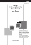
SDC15
Single Loop Controller
User's Manual
for
Installation & Configuration
Thank you for purchasing the SDC15
Single Loop Controller.
This manual contains information for
ensuring correct use of the SDC15. It
also provides necessary information for
installation, maintenance, and troubleshooting.
This manual should be read by those
who design and maintain devices that
use the SDC15. Be sure to keep this
manual nearby for handy reference.
Getting Up to Speed with the SDC15
The quick reference guide on pages D-1 to D-8 summarizes key operations,
parameters, and settings, and gives concrete operation examples using illustrations.
Try looking at these pages first, and then read the main text for details.
A separate color version of the quick guide printed on dirt-resistant paper is available
for convenient use on the work site (document No. CP-SP-1213E). Contact Yamatake
Corporation or a distributor for details.
NOTICE
Be sure that the user receives this manual before the product is used.
Copying or duplicating this user’s manual in part or in whole is forbidden. The information and specifications in this manual are subject to
change without notice.
Considerable effort has been made to ensure that this manual is free
from inaccuracies and omissions. If you should find an error or omission, please contact Yamatake Corporation.
In no event is Yamatake Corporation liable to anyone for any indirect,
special or consequential damages as a result of using this product.
©2003 Yamatake Corporation ALL RIGHTS RESERVED
SAFETY REQUIREMENTS
To reduce risk of electric shock which could cause personal injury, follow all safety
notices in this documentation.
This symbol warns the user of a potential shock hazard where hazardous live voltages
may be accessible.
•
•
•
•
•
If the equipment is used in a manner not specified by the manufacturer, the protection
provided by the equipment must be impaired.
Do not replace any component (or part) not explicitly specified as replaceable by your
supplier.
All wiring must be in accordance with local norms and carried out by authorized and
experienced personnel.
A switch in the main supply is required near the equipment.
Main power supply wiring requires a (T) 200mA, 250V fuse(s) (IEC 127).
EQUIPMENT RATINGS
Supply voltages:
100 to 240V (operating power supply voltage 85 to 264Vac)
Frequency:
50/60Hz
Power consumption:
12VA maximum
EQUIPMENT CONDITIONS
Do not operate the instrument in the presence of flammable liquids or vapors.
Operation of any electrical instrument in such an environment constitutes a safety hazard.
Temperature:
0 to 50˚C
Humidity:
10 to 90%RH (no condensation)
Vibration:
2m/s2 (10 to 60Hz)
Over-voltage category:
Category II (IEC60364-4-443, IEC60664-1)
Pollution degree:
Pollution degree 2
EQUIPMENT INSTALLATION
The controller must be mounted into a panel to limit operator access to the rear terminal.
Specifications of common mode voltage: The common mode voltages of all I/O except for main
supply and relay outputs are less than 33Vrms, 46.7V peak and 70Vdc.
APPLICABLE STANDARDS
EN61010-1, EN61326-1
i
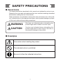
SAFETY PRECAUTIONS
■ About Icons
The safety precautions described in this manual are indicated by various icons.
Please be sure you read and understand the icons and their meanings described
below before reading the rest of the manual.
Safety precautions are intended to ensure the safe and correct use of this product, to prevent injury to the operator and others, and to prevent damage to property. Be sure to observe these safety precautions.
WARNING
Warnings are indicated when mishandling this
product might result in death or serious injury.
CAUTION
Cautions are indicated when mishandling this
product might result in minor injury to the user, or
only physical damage to the product.
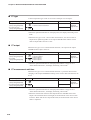
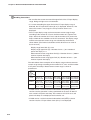
■ Examples
Use caution when handling the product.
The indicated action is prohibited.
Be sure to follow the indicated instructions.
ii
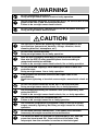
WARNING
Do not disassemble the SDC15.
Doing so might cause electric shock or faulty operation.
Before removing, mounting, or wiring the SDC15, be sure to turn off the
power to the SDC15 and all connected devices.
Failure to do so might cause electric shock.
Do not touch electrically charged parts such as the power terminals.
Doing so might cause electric shock.
CAUTION
Use the SDC15 within the operating ranges recommended in the
specifications (temperature, humidity, voltage, vibration, shock,
mounting direction, atmosphere, etc.).
Do not block ventilation holes.
Doing so might cause fire or faulty operation.
Wire the SDC15 properly according to predetermined standards.
Also wire the SDC15 using specified power leads according to
recognized installation methods.
Failure to do so might cause electric shock, fire or faulty operation.
Do not allow lead clippings, metal shavings or water to enter the
controller case.
Doing so might cause fire or faulty operation.
Firmly tighten the terminal screws at the torque listed in the
specifications.
Insufficient tightening of terminal screws might cause electric shock or
fire.
Do not use unused terminals on the SDC15 as relay terminals.
Doing so might cause electric shock, fire, or faulty operation.
We recommend attaching the terminal cover (sold separately) after
wiring the SDC15.
Failure to do so might cause electric shock, fire, or faulty operation.
Use the relays within the recommended life.
Failure to do so might cause fire or faulty operation.
Use Yamatake Corporation's SurgeNon if there is the risk of power
surges caused by lightning. Not doing so might cause fire or faulty
operation.
Do not make incorrect connections. If the cables are connected
incorrectly, this might cause the unit to malfunction.
The controller does not function for approximately 6 sec. after the
power has been turned ON. Great care should be taken if the
relayoutput from the controller is used as an interlock signal.
iii
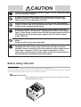
CAUTION
There is no isolation between control outputs 1 and 2. When necessary,
use an appopriate isolator.
Do not connect multiple loader cables to multiple units from one
personal computer. The current coming from other circuits might
cause an error in the indication of the PV.
When wiring RS-485 communications, do not connect a terminating
resistor to either end of the communication path. A terminating resistor
might cause a communication failure.
Be sure to provide a switch for cutoff of the main power to this unit
within easy reach of the operator. Additionally, connect a slow-action
type (T) fuse having a rated current of 0.2A and rated voltage of 250V to
the wiring for the instrument power supply of the AC power supply
model. (IEC127)
Do not operate the keys with a mechanical pencil or other sharp-tipped
object.
Doing so might cause faulty operation.
In addition to ON/OFF control and conventional PID control, this unit is
equipped with self-tuning control, which does not require manual
setting of control constants. Self-tuning control ensures stable control
even after a change in the SP or an external disturbance. This is
achieved by monitoring the control target, learning its characteristics,
and automatically calculating control constants.
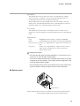
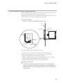
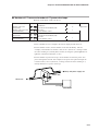
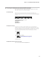
Before Using This Unit
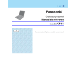
The protective film is adhered to the front console of this unit to protect the surface.
After the installation and wiring work has been completed, stick a scotch tape to the corner of the console and pull it
out in the direction indicated by an arrow to peel off the protective film.
Handling Precautions
If you attempt to peel off the protective film with your fingernail, this might
cause damage to the console.
Adhesive tape
Pull out.
mo
de
rdy
pa
ra
ma
n
ev
1
ev
2
ev
3
ot1
ot2
iv
The Role of This Manual
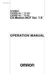
Five different manuals in total are available for the SDC15 Single Loop Controller (hereafter referred to as
"this unit"). Read appropriate manuals according to your requirements. If you do not have a required manual,
contact Yamatake Corporation or its dealer. Additionally, you can download necessary manuals from
http://www.yamatake.com.
The user level of this unit can be selected from three levels, "Simple configuration", "Standard configuration", and
"High function configuration." The functions you can set up only with "Simple configuration" are described in
SDC15 Single Loop Controller User's Manual for Basic Operation (CP-SP-1147E). If more advanced application
is needed, refer to this manual. This manual is intended for personnel who have already read SDC15 Single Loop
Controller User's Manual for Basic Operation and/or operated Yamatake's Single Loop Controller to fully
understand its basic operation.
User’
al
s Manu
ING
WARN
N
CAUTIO
SDC15 Single Loop Controller User's Manual for Installation
Manual No. CP-UM-5287JE
NG
WARNI
This manual is supplied with the product. Personnel in charge of design
and/or manufacture of a system using this unit must thoroughly read this
manual. This manual describes the safety precautions, installation, wiring,
list of parameters, and primary specifications. For further information about
operation, refer to other manuals, Basic Operation and/or Installation &
Configuration.
N
CAUTIO
SDC15 Single Loop Controller User's Manual for Basic Operation
Manual No. CP-SP-1147E
This manual is optional (sold separately). The manual describes the
functions you can set up only with "Simple configuration". Personnel in
charge of design, manufacture, operation, and/or maintenance of a system
using this unit must thoroughly read this manual. This manual describes
the installation, wiring, major functions and settings, operating procedures,
troubleshooting, and detailed specifications.
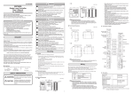
SDC15 Single Loop Controller User's Manual for
Installation & Configuration
Manual No. CP-SP-1148E
This manual. This manual is optional (sold separately). The manual
describes the hardware and all functions of this unit. Personnel in charge
of design, manufacture, operation, and/or maintenance of a system using
this unit and those in charge of communication software of a system using
the communication functions of this unit must thoroughly read this manual.
This manual also describes the installation, wiring, connections for
communication, all functions and settings of this unit, operating procedures,
communication with host station, such as personal computer,
communication addresses, troubleshooting, and detailed specifications.
SLP-C35 Smart Loader Package for SDC15/25/26/35/36 Single Loop
Controller User's Manual
Manual No. CP-UM-5290E
This manual is supplied with the Smart Loader Package. The manual
describes the software used to make various settings for SDC15/25/26/35/
36 using a personal computer. Personnel in charge of design or setting of
a system using SDC15/25/26/35/36 must thoroughly read this manual. The
manual describes installation of the software into a personal computer,
operation of the personal computer, various functions, and setup
procedures.
CP-SP-
1213E
ide
ence Gu
ick Refer
Qu
SDC15
SDC15 Quick Reference Guide
Manual No. CP-UM-1213E
For those using the SDC15 for the first time or for operators on the work
site, this guide serves as a reference when setting or modifying
parameters. Key operations, menu flowcharts and parameter settings are
presented with color illustrations.
v
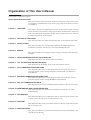
Organization of This User's Manual
This manual is organized as follows:
SDC15 Quick Reference Guide
This guide contains menu flowcharts, parameter settings lists, and concrete operation examples, with illustrations. Look at these pages first for an effective overview
of the SDC15.
Chapter 1. OVERVIEW
This chapter describes the applications, features, model selection guide, and part
names and functions of this unit. Since the part names described in this chapter are
used in the subsequent descriptions, the part names and functions of this unit must
be understood correctly in this chapter.
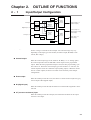
Chapter 2. OUTLINE OF FUNCTIONS
This chapter describes the outline and operation flow of the functions of this unit.
Chapter 3. INSTALLATION
This chapter describes the environmental conditions, installation dimensions,
installation procedures, and necessary tools when installing this unit.
Chapter 4. WIRING
This chapter describes the wiring procedures, wiring precautions, and connection
examples.
Chapter 5. DETAILED DESCRIPTION OF EACH FUNCTION
This chapter describes each function of this unit in detail.
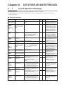
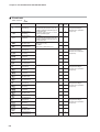
Chapter 6. LIST OF DISPLAYS AND SETTING DATA
This chapter lists up the display items of this unit and their contents.
Chapter 7. CPL COMMUNICATIONS FUNCTIONS
This chapter describes how to communicate this unit with a host unit, such as a
personal computer or PLC through Yamatake's standard CPL communication
using RS-485.
Chapter 8. MODBUS COMMUNICATIONS FUNCTIONS
This chapter describes how to communicate this unit with a host unit, such as a
personal computer or PLC through MODBUS communication.
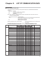
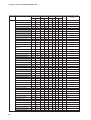
Chapter 9. LIST OF COMMUNICATION DATA
This chapter shows the list of communication data inside the memory of this unit.
Chapter 10. MAINTENANCE AND TROUBLESHOOTING
This chapter describes the maintenance and inspection of this unit, as well as
troubleshooting.
Chapter 11. CALIBRATION
This chapter describes how to calibrate this unit in order to keep the accuracy and
to safely operate this unit for an extended period of time.
Chapter 12. DISPOSAL
This chapter describes safety precautions and how to dispose of this unit when the
unit is no longer used.
Chapter 13. SPECIFICATIONS
This chapter describes the general specifications, performance specifications, and
optional parts of this unit.
vi
Contents
SAFETY REQUIREMENTS
SAFETY PRECAUTIONS
Important Notice Prior to Use of This Unit
The Role of This Manual
Organization of This User's Manual
Conventions Used in This Manual
SDC15 Quick Reference Guide
Part names • • • • • • • • • • • • • • • • • • • • • • • • • • • • • • • • • • • • • • • • • • • • • • • • • • • • • • • • • • • • • • • • • • • • • D-1
Flowchart of key operations and displays • • • • • • • • • • • • • • • • • • • • • • • • • • • • • • • D-2 to D-3
Operation examples • • • • • • • • • • • • • • • • • • • • • • • • • • • • • • • • • • • • • • • • • • • • • • • • • • • • • D-4 to D-5
List of parameter • • • • • • • • • • • • • • • • • • • • • • • • • • • • • • • • • • • • • • • • • • • • • • • • • • • • • • • • D-6 to D-7
PV input range table • • • • • • • • • • • • • • • • • • • • • • • • • • • • • • • • • • • • • • • • • • • • • • • • • • • • • • • • • • • • D-8
List of alarm code • • • • • • • • • • • • • • • • • • • • • • • • • • • • • • • • • • • • • • • • • • • • • • • • • • • • • • • • • • • • • • D-8
Event type • • • • • • • • • • • • • • • • • • • • • • • • • • • • • • • • • • • • • • • • • • • • • • • • • • • • • • • • • • • • • • • • • • • • • • D-8
Chapter 1.
OVERVIEW
1-1 Overview • • • • • • • • • • • • • • • • • • • • • • • • • • • • • • • • • • • • • • • • • • • • • • • • • • • • • • • • • • • • • • • • • • • 1-1
■ Model selection table • • • • • • • • • • • • • • • • • • • • • • • • • • • • • • • • • • • • • • • • • • • • • • • • • • 1-2
■ Accessories and optional parts • • • • • • • • • • • • • • • • • • • • • • • • • • • • • • • • • • • • • • • • 1-3
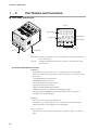
1-2 Part Names and Functions • • • • • • • • • • • • • • • • • • • • • • • • • • • • • • • • • • • • • • • • • • • • • • • • • 1-4
■ Main body and console • • • • • • • • • • • • • • • • • • • • • • • • • • • • • • • • • • • • • • • • • • • • • • • • 1-4
■ Bottom panel • • • • • • • • • • • • • • • • • • • • • • • • • • • • • • • • • • • • • • • • • • • • • • • • • • • • • • • • • • 1-5
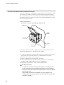
■ Rear panel • • • • • • • • • • • • • • • • • • • • • • • • • • • • • • • • • • • • • • • • • • • • • • • • • • • • • • • • • • • • • 1-6
Chapter 2.
OUTLINE OF FUNCTIONS
2-1 Input/Output Configuration • • • • • • • • • • • • • • • • • • • • • • • • • • • • • • • • • • • • • • • • • • • • • • • • 2-1
2-2 Key Operation • • • • • • • • • • • • • • • • • • • • • • • • • • • • • • • • • • • • • • • • • • • • • • • • • • • • • • • • • • • • • 2-2
■ Standard key operation type • • • • • • • • • • • • • • • • • • • • • • • • • • • • • • • • • • • • • • • • • • • 2-2
■ Special key operation type • • • • • • • • • • • • • • • • • • • • • • • • • • • • • • • • • • • • • • • • • • • • 2-4
■ Data setting procedures • • • • • • • • • • • • • • • • • • • • • • • • • • • • • • • • • • • • • • • • • • • • • • • 2-6
■ [mode] key operating procedures • • • • • • • • • • • • • • • • • • • • • • • • • • • • • • • • • • • • • 2-7
■ User level • • • • • • • • • • • • • • • • • • • • • • • • • • • • • • • • • • • • • • • • • • • • • • • • • • • • • • • • • • • • • • 2-8
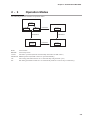
2-3 Operation Modes • • • • • • • • • • • • • • • • • • • • • • • • • • • • • • • • • • • • • • • • • • • • • • • • • • • • • • • • • • 2-9
Chapter 3.
INSTALLATION
■
■
■
■
Installation place • • • • • • • • • • • • • • • • • • • • • • • • • • • • • • • • • • • • • • • • • • • • • • • • • • • • • • • 3-1
External dimensions • • • • • • • • • • • • • • • • • • • • • • • • • • • • • • • • • • • • • • • • • • • • • • • • • • • 3-2
Panel cutout dimensions• • • • • • • • • • • • • • • • • • • • • • • • • • • • • • • • • • • • • • • • • • • • • • • 3-2
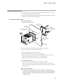
Mounting procedures • • • • • • • • • • • • • • • • • • • • • • • • • • • • • • • • • • • • • • • • • • • • • • • • • • 3-3
vii
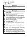
Chapter 4.
WIRING
4-1 Wiring• • • • • • • • • • • • • • • • • • • • • • • • • • • • • • • • • • • • • • • • • • • • • • • • • • • • • • • • • • • • • • • • • • • • • • 4-1
■ Terminal assignment label symbols • • • • • • • • • • • • • • • • • • • • • • • • • • • • • • • • • • • 4-2
■ Wiring precautions • • • • • • • • • • • • • • • • • • • • • • • • • • • • • • • • • • • • • • • • • • • • • • • • • • • • 4-2
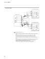
■ Connection of open collector output to digital input • • • • • • • • • • • • • • • • • • • 4-5
■ Connection of communication (RS-485) cable • • • • • • • • • • • • • • • • • • • • • • • • • 4-5
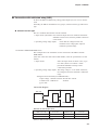
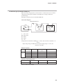
■ Connection with solid state relay (SSR) • • • • • • • • • • • • • • • • • • • • • • • • • • • • • • • • 4-7
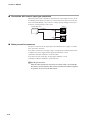
■ Connection with current-input type controllers • • • • • • • • • • • • • • • • • • • • • • • 4-10
■ Noise preventive measures • • • • • • • • • • • • • • • • • • • • • • • • • • • • • • • • • • • • • • • • • • • 4-10
4-2 Recommended Cables• • • • • • • • • • • • • • • • • • • • • • • • • • • • • • • • • • • • • • • • • • • • • • • • • • • • 4-11
Chapter 5.
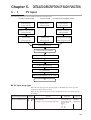
DETAILED DESCRIPTION OF EACH FUNCTION
5-1 PV Input • • • • • • • • • • • • • • • • • • • • • • • • • • • • • • • • • • • • • • • • • • • • • • • • • • • • • • • • • • • • • • • • • • • 5-1
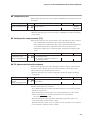
■ PV input range type • • • • • • • • • • • • • • • • • • • • • • • • • • • • • • • • • • • • • • • • • • • • • • • • • • • 5-1
■ Temperature unit • • • • • • • • • • • • • • • • • • • • • • • • • • • • • • • • • • • • • • • • • • • • • • • • • • • • • • 5-3
■ Cold junction compensation (T/C) • • • • • • • • • • • • • • • • • • • • • • • • • • • • • • • • • • • • • 5-3
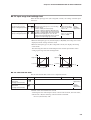
■ PV square root extraction dropout • • • • • • • • • • • • • • • • • • • • • • • • • • • • • • • • • • • • 5-3
■ Decimal point position • • • • • • • • • • • • • • • • • • • • • • • • • • • • • • • • • • • • • • • • • • • • • • • • 5-4
■ PV input range low limit/high limit • • • • • • • • • • • • • • • • • • • • • • • • • • • • • • • • • • • • • 5-5
■ PV ratio and PV bias • • • • • • • • • • • • • • • • • • • • • • • • • • • • • • • • • • • • • • • • • • • • • • • • • • • 5-5
■ PV filter • • • • • • • • • • • • • • • • • • • • • • • • • • • • • • • • • • • • • • • • • • • • • • • • • • • • • • • • • • • • • • • • 5-6
■ PV hold • • • • • • • • • • • • • • • • • • • • • • • • • • • • • • • • • • • • • • • • • • • • • • • • • • • • • • • • • • • • • • • • 5-6
■ PV low limit/high limit and PV low limit/high limit alarms • • • • • • • • • • • • • • 5-6
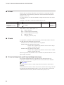
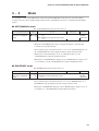
5-2 Mode • • • • • • • • • • • • • • • • • • • • • • • • • • • • • • • • • • • • • • • • • • • • • • • • • • • • • • • • • • • • • • • • • • • • • • • 5-7
■ AUTO/MANUAL mode • • • • • • • • • • • • • • • • • • • • • • • • • • • • • • • • • • • • • • • • • • • • • • • • • 5-7
■ RUN/READY mode • • • • • • • • • • • • • • • • • • • • • • • • • • • • • • • • • • • • • • • • • • • • • • • • • • • • 5-7
■ AT (Auto Tuning) stop/start • • • • • • • • • • • • • • • • • • • • • • • • • • • • • • • • • • • • • • • • • • • 5-8
■ Release all DO (digital output) latches • • • • • • • • • • • • • • • • • • • • • • • • • • • • • • • • 5-8
■ Communication DI (digital input) 1 • • • • • • • • • • • • • • • • • • • • • • • • • • • • • • • • • • • • 5-8
5-3 Control • • • • • • • • • • • • • • • • • • • • • • • • • • • • • • • • • • • • • • • • • • • • • • • • • • • • • • • • • • • • • • • • • • • • • 5-9
■ Control method • • • • • • • • • • • • • • • • • • • • • • • • • • • • • • • • • • • • • • • • • • • • • • • • • • • • • • 5-11
■ Control action and Heat/Cool control • • • • • • • • • • • • • • • • • • • • • • • • • • • • • • • • 5-12
■ Special control outputs • • • • • • • • • • • • • • • • • • • • • • • • • • • • • • • • • • • • • • • • • • • • • • 5-12
■ MANUAL mode change • • • • • • • • • • • • • • • • • • • • • • • • • • • • • • • • • • • • • • • • • • • • • • 5-13
■ ON/OFF control • • • • • • • • • • • • • • • • • • • • • • • • • • • • • • • • • • • • • • • • • • • • • • • • • • • • • • 5-13
■ PID control • • • • • • • • • • • • • • • • • • • • • • • • • • • • • • • • • • • • • • • • • • • • • • • • • • • • • • • • • • • 5-14
■ Heat/Cool control • • • • • • • • • • • • • • • • • • • • • • • • • • • • • • • • • • • • • • • • • • • • • • • • • • • • 5-15
■ ST (Self-tuning) • • • • • • • • • • • • • • • • • • • • • • • • • • • • • • • • • • • • • • • • • • • • • • • • • • • • • • 5-17
■ AT (Auto-tuning) • • • • • • • • • • • • • • • • • • • • • • • • • • • • • • • • • • • • • • • • • • • • • • • • • • • • • 5-18
■ Just-FiTTER • • • • • • • • • • • • • • • • • • • • • • • • • • • • • • • • • • • • • • • • • • • • • • • • • • • • • • • • • • 5-20
■ RationaLOOP • • • • • • • • • • • • • • • • • • • • • • • • • • • • • • • • • • • • • • • • • • • • • • • • • • • • • • • • 5-20
■ SP lag • • • • • • • • • • • • • • • • • • • • • • • • • • • • • • • • • • • • • • • • • • • • • • • • • • • • • • • • • • • • • • • • 5-20
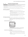
5-4 AT (auto tuning) Function • • • • • • • • • • • • • • • • • • • • • • • • • • • • • • • • • • • • • • • • • • • • • • • • 5-21
■ Starting procedures • • • • • • • • • • • • • • • • • • • • • • • • • • • • • • • • • • • • • • • • • • • • • • • • • • 5-21
■ Stopping procedures • • • • • • • • • • • • • • • • • • • • • • • • • • • • • • • • • • • • • • • • • • • • • • • • • 5-21
viii
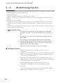
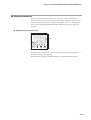
5-5 ST (Self-tuning) Function • • • • • • • • • • • • • • • • • • • • • • • • • • • • • • • • • • • • • • • • • • • • • • • • • 5-24
■ Starting procedures • • • • • • • • • • • • • • • • • • • • • • • • • • • • • • • • • • • • • • • • • • • • • • • • • • 5-24
■ Stopping procedures • • • • • • • • • • • • • • • • • • • • • • • • • • • • • • • • • • • • • • • • • • • • • • • • • 5-25
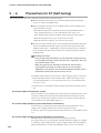
5-6 Precautions for ST (Self-tuning) • • • • • • • • • • • • • • • • • • • • • • • • • • • • • • • • • • • • • • • • • • 5-26
5-7 SP • • • • • • • • • • • • • • • • • • • • • • • • • • • • • • • • • • • • • • • • • • • • • • • • • • • • • • • • • • • • • • • • • • • • • • • 5-27
■ SP setup in operation display mode • • • • • • • • • • • • • • • • • • • • • • • • • • • • • • • • • 5-28
■ LSP system group • • • • • • • • • • • • • • • • • • • • • • • • • • • • • • • • • • • • • • • • • • • • • • • • • • • 5-28
■ LSP1 to 4 • • • • • • • • • • • • • • • • • • • • • • • • • • • • • • • • • • • • • • • • • • • • • • • • • • • • • • • • • • • • • 5-28
■ LSP group number • • • • • • • • • • • • • • • • • • • • • • • • • • • • • • • • • • • • • • • • • • • • • • • • • • • 5-28
■ DI Assignment of LSP group selection • • • • • • • • • • • • • • • • • • • • • • • • • • • • • • • 5-29
■ SP ramp unit • • • • • • • • • • • • • • • • • • • • • • • • • • • • • • • • • • • • • • • • • • • • • • • • • • • • • • • • • 5-30
■ SP up ramp/down ramp • • • • • • • • • • • • • • • • • • • • • • • • • • • • • • • • • • • • • • • • • • • • • • 5-30
■ SP low limit/high limit • • • • • • • • • • • • • • • • • • • • • • • • • • • • • • • • • • • • • • • • • • • • • • • • 5-31
■ DI Assignment of SP ramp enabled/disabled • • • • • • • • • • • • • • • • • • • • • • • • • 5-31
5-8 DI (Digital Input) and Internal Contact • • • • • • • • • • • • • • • • • • • • • • • • • • • • • • • • • • • • 5-32
■ Operation type • • • • • • • • • • • • • • • • • • • • • • • • • • • • • • • • • • • • • • • • • • • • • • • • • • • • • • • 5-33
■ Event channel def. • • • • • • • • • • • • • • • • • • • • • • • • • • • • • • • • • • • • • • • • • • • • • • • • • • • 5-34
■ Input bit function • • • • • • • • • • • • • • • • • • • • • • • • • • • • • • • • • • • • • • • • • • • • • • • • • • • • • 5-34
■ Input assign • • • • • • • • • • • • • • • • • • • • • • • • • • • • • • • • • • • • • • • • • • • • • • • • • • • • • • • • • • 5-35
■ Polarity of input assign • • • • • • • • • • • • • • • • • • • • • • • • • • • • • • • • • • • • • • • • • • • • • • 5-36
■ Polarity of input bit function • • • • • • • • • • • • • • • • • • • • • • • • • • • • • • • • • • • • • • • • • 5-36
■ DI Assignment setting with Smart Loader Package SLP-C35 • • • • • • • • 5-37
5-9 Internal Event • • • • • • • • • • • • • • • • • • • • • • • • • • • • • • • • • • • • • • • • • • • • • • • • • • • • • • • • • • • • • 5-38
■ Operation • • • • • • • • • • • • • • • • • • • • • • • • • • • • • • • • • • • • • • • • • • • • • • • • • • • • • • • • • • • • 5-39
■ Operation type • • • • • • • • • • • • • • • • • • • • • • • • • • • • • • • • • • • • • • • • • • • • • • • • • • • • • • • 5-45
■ Direct/reverse, standby, and EVENT state at READY • • • • • • • • • • • • • • • • • 5-46
■ Alarm OR, special OFF setup, and delay time unit • • • • • • • • • • • • • • • • • • • 5-47
■ Main setting, sub setting, and hysteresis • • • • • • • • • • • • • • • • • • • • • • • • • • • • 5-48
■ ON delay and OFF delay • • • • • • • • • • • • • • • • • • • • • • • • • • • • • • • • • • • • • • • • • • • • • 5-49
5-10 DO (Digital Output) • • • • • • • • • • • • • • • • • • • • • • • • • • • • • • • • • • • • • • • • • • • • • • • • • • • • • • • 5-51
■ MV1/MV2 process • • • • • • • • • • • • • • • • • • • • • • • • • • • • • • • • • • • • • • • • • • • • • • • • • • • • 5-52
■ Operation type • • • • • • • • • • • • • • • • • • • • • • • • • • • • • • • • • • • • • • • • • • • • • • • • • • • • • • • 5-53
■ Output assign • • • • • • • • • • • • • • • • • • • • • • • • • • • • • • • • • • • • • • • • • • • • • • • • • • • • • • • • 5-54
■ Polarity of output assign • • • • • • • • • • • • • • • • • • • • • • • • • • • • • • • • • • • • • • • • • • • • 5-56
■ Polarity of output bit function • • • • • • • • • • • • • • • • • • • • • • • • • • • • • • • • • • • • • • • • 5-57
■ Latch • • • • • • • • • • • • • • • • • • • • • • • • • • • • • • • • • • • • • • • • • • • • • • • • • • • • • • • • • • • • • • • • • 5-57
■ DO Assignment setting with Smart Loader Package SLP-C35 • • • • • • • 5-58
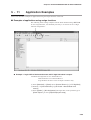
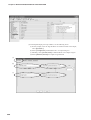
5-11 Application Examples • • • • • • • • • • • • • • • • • • • • • • • • • • • • • • • • • • • • • • • • • • • • • • • • • • • • 5-59
■ Examples of applications using assign functions • • • • • • • • • • • • • • • • • • • • 5-59
5-12 Continuous Output • • • • • • • • • • • • • • • • • • • • • • • • • • • • • • • • • • • • • • • • • • • • • • • • • • • • • • • 5-66
■ Output range • • • • • • • • • • • • • • • • • • • • • • • • • • • • • • • • • • • • • • • • • • • • • • • • • • • • • • • • • 5-66
■ Output type • • • • • • • • • • • • • • • • • • • • • • • • • • • • • • • • • • • • • • • • • • • • • • • • • • • • • • • • • • 5-66
■ Output scaling low limit/high limit • • • • • • • • • • • • • • • • • • • • • • • • • • • • • • • • • • • • 5-67
■ MV scaling range • • • • • • • • • • • • • • • • • • • • • • • • • • • • • • • • • • • • • • • • • • • • • • • • • • • • • 5-68
5-13 CT (Current Transformer) Input • • • • • • • • • • • • • • • • • • • • • • • • • • • • • • • • • • • • • • • • • • • 5-69
■ CT type • • • • • • • • • • • • • • • • • • • • • • • • • • • • • • • • • • • • • • • • • • • • • • • • • • • • • • • • • • • • • • • 5-70
■ CT output • • • • • • • • • • • • • • • • • • • • • • • • • • • • • • • • • • • • • • • • • • • • • • • • • • • • • • • • • • • • 5-70
■ CT measurement wait time • • • • • • • • • • • • • • • • • • • • • • • • • • • • • • • • • • • • • • • • • • • 5-70
ix
■ Number of CT turns and number of CT power wire loops • • • • • • • • • • • • 5-71
5-14 Console Display and Key Operation • • • • • • • • • • • • • • • • • • • • • • • • • • • • • • • • • • • • • • 5-73
■ Key operation type • • • • • • • • • • • • • • • • • • • • • • • • • • • • • • • • • • • • • • • • • • • • • • • • • • • 5-73
■ [mode] key function • • • • • • • • • • • • • • • • • • • • • • • • • • • • • • • • • • • • • • • • • • • • • • • • • • 5-73
■ MODE display setup • • • • • • • • • • • • • • • • • • • • • • • • • • • • • • • • • • • • • • • • • • • • • • • • • 5-74
■ PV/SP display setup • • • • • • • • • • • • • • • • • • • • • • • • • • • • • • • • • • • • • • • • • • • • • • • • • • 5-75
■ MV display setup • • • • • • • • • • • • • • • • • • • • • • • • • • • • • • • • • • • • • • • • • • • • • • • • • • • • • 5-76
■ EV display setup • • • • • • • • • • • • • • • • • • • • • • • • • • • • • • • • • • • • • • • • • • • • • • • • • • • • • 5-77
■ Timer remain time display setup • • • • • • • • • • • • • • • • • • • • • • • • • • • • • • • • • • • • • 5-77
■ CT display setup • • • • • • • • • • • • • • • • • • • • • • • • • • • • • • • • • • • • • • • • • • • • • • • • • • • • • 5-78
■ User level • • • • • • • • • • • • • • • • • • • • • • • • • • • • • • • • • • • • • • • • • • • • • • • • • • • • • • • • • • • • 5-78
■ Communication monitor display • • • • • • • • • • • • • • • • • • • • • • • • • • • • • • • • • • • • • 5-78
■ User Function • • • • • • • • • • • • • • • • • • • • • • • • • • • • • • • • • • • • • • • • • • • • • • • • • • • • • • • • 5-79
■ Key lock, communication lock, and loader lock • • • • • • • • • • • • • • • • • • • • • • 5-83
■ Password • • • • • • • • • • • • • • • • • • • • • • • • • • • • • • • • • • • • • • • • • • • • • • • • • • • • • • • • • • • • 5-84
Chapter 6. LIST OF DISPLAYS AND SETTING DATA
6-1 List of Operation Displays • • • • • • • • • • • • • • • • • • • • • • • • • • • • • • • • • • • • • • • • • • • • • • • • • 6-1
■ Operation displays • • • • • • • • • • • • • • • • • • • • • • • • • • • • • • • • • • • • • • • • • • • • • • • • • • • • • 6-1
6-2 List of Parameter Setting Displays • • • • • • • • • • • • • • • • • • • • • • • • • • • • • • • • • • • • • • • • • 6-3
■ Mode bank • • • • • • • • • • • • • • • • • • • • • • • • • • • • • • • • • • • • • • • • • • • • • • • • • • • • • • • • • • • • • 6-3
■ SP bank • • • • • • • • • • • • • • • • • • • • • • • • • • • • • • • • • • • • • • • • • • • • • • • • • • • • • • • • • • • • • • • • 6-3
■ Event bank • • • • • • • • • • • • • • • • • • • • • • • • • • • • • • • • • • • • • • • • • • • • • • • • • • • • • • • • • • • • • 6-4
■ PID bank • • • • • • • • • • • • • • • • • • • • • • • • • • • • • • • • • • • • • • • • • • • • • • • • • • • • • • • • • • • • • • • 6-5
■ Parameter bank • • • • • • • • • • • • • • • • • • • • • • • • • • • • • • • • • • • • • • • • • • • • • • • • • • • • • • • • 6-6
■ Extended tuning bank • • • • • • • • • • • • • • • • • • • • • • • • • • • • • • • • • • • • • • • • • • • • • • • • • • 6-7
6-3 List of Setup Setting Displays • • • • • • • • • • • • • • • • • • • • • • • • • • • • • • • • • • • • • • • • • • • • • 6-8
■ Setup bank • • • • • • • • • • • • • • • • • • • • • • • • • • • • • • • • • • • • • • • • • • • • • • • • • • • • • • • • • • • • • 6-8
■ Event configuration bank • • • • • • • • • • • • • • • • • • • • • • • • • • • • • • • • • • • • • • • • • • • • • 6-13
■ DI Assignment bank • • • • • • • • • • • • • • • • • • • • • • • • • • • • • • • • • • • • • • • • • • • • • • • • • • 6-16
■ DO Assignment bank • • • • • • • • • • • • • • • • • • • • • • • • • • • • • • • • • • • • • • • • • • • • • • • • • 6-19
■ User Function bank • • • • • • • • • • • • • • • • • • • • • • • • • • • • • • • • • • • • • • • • • • • • • • • • • • • 6-23
■ Lock bank• • • • • • • • • • • • • • • • • • • • • • • • • • • • • • • • • • • • • • • • • • • • • • • • • • • • • • • • • • • • • 6-23
■ Instrument information bank• • • • • • • • • • • • • • • • • • • • • • • • • • • • • • • • • • • • • • • • • • 6-24
Chapter 7.
CPL COMMUNICATIONS FUNCTIONS
7-1 Outline of Communications • • • • • • • • • • • • • • • • • • • • • • • • • • • • • • • • • • • • • • • • • • • • • • • • 7-1
■ Features • • • • • • • • • • • • • • • • • • • • • • • • • • • • • • • • • • • • • • • • • • • • • • • • • • • • • • • • • • • • • • • 7-1
■ Setup • • • • • • • • • • • • • • • • • • • • • • • • • • • • • • • • • • • • • • • • • • • • • • • • • • • • • • • • • • • • • • • • • • 7-1
■ Communications procedures • • • • • • • • • • • • • • • • • • • • • • • • • • • • • • • • • • • • • • • • • • 7-2
7-2 Message Structure • • • • • • • • • • • • • • • • • • • • • • • • • • • • • • • • • • • • • • • • • • • • • • • • • • • • • • • • • 7-3
■ Message structure • • • • • • • • • • • • • • • • • • • • • • • • • • • • • • • • • • • • • • • • • • • • • • • • • • • • • 7-3
■ Data link layer • • • • • • • • • • • • • • • • • • • • • • • • • • • • • • • • • • • • • • • • • • • • • • • • • • • • • • • • • 7-3
■ Application layer • • • • • • • • • • • • • • • • • • • • • • • • • • • • • • • • • • • • • • • • • • • • • • • • • • • • • • 7-5
x
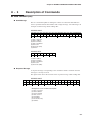
7-3 Description of Commands • • • • • • • • • • • • • • • • • • • • • • • • • • • • • • • • • • • • • • • • • • • • • • • • • 7-6
■ Continuous data read command (RS command) • • • • • • • • • • • • • • • • • • • • • • 7-6
■ Continuous data write command (WS command) • • • • • • • • • • • • • • • • • • • • • 7-7
■ Fixed length continuous data read command (RD command) • • • • • • • • • 7-8
■ Fixed length continuous data write command (WD command) • • • • • • • • 7-9
■ Fixed length random data read command (RU command) • • • • • • • • • • • 7-10
■ Fixed length random data write command (WU command) • • • • • • • • • • 7-11
7-4 Definition of Word Addresses • • • • • • • • • • • • • • • • • • • • • • • • • • • • • • • • • • • • • • • • • • • • 7-12
7-5 Numeric Representation in the Application Layer • • • • • • • • • • • • • • • • • • • • • • • • 7-13
7-6 List of Termination Codes • • • • • • • • • • • • • • • • • • • • • • • • • • • • • • • • • • • • • • • • • • • • • • • • 7-14
7-7 Reception and Transmission Timing • • • • • • • • • • • • • • • • • • • • • • • • • • • • • • • • • • • • • 7-15
■ Timing specifications for instruction and response message • • • • • • • • 7-15
■ RS-485 driver control timing specifications • • • • • • • • • • • • • • • • • • • • • • • • • • 7-15
7-8 Cautions when Making Communications Programs
for the Master Station• • • • • • • • • • • • • • • • • • • • • • • • • • • • • • • • • • • • • • • • • • • • • • • • • • • • • 7-16
■ Example of communications program • • • • • • • • • • • • • • • • • • • • • • • • • • • • • • • 7-16
Chapter 8. MODBUS COMMUNICATIONS FUNCTIONS
8-1 Outline of Communications • • • • • • • • • • • • • • • • • • • • • • • • • • • • • • • • • • • • • • • • • • • • • • • • 8-1
■ Features • • • • • • • • • • • • • • • • • • • • • • • • • • • • • • • • • • • • • • • • • • • • • • • • • • • • • • • • • • • • • • • 8-1
■ Setup • • • • • • • • • • • • • • • • • • • • • • • • • • • • • • • • • • • • • • • • • • • • • • • • • • • • • • • • • • • • • • • • • • 8-1
■ Communications procedures • • • • • • • • • • • • • • • • • • • • • • • • • • • • • • • • • • • • • • • • • • 8-2
8-2 Message Structure • • • • • • • • • • • • • • • • • • • • • • • • • • • • • • • • • • • • • • • • • • • • • • • • • • • • • • • • • 8-3
■ Message structure • • • • • • • • • • • • • • • • • • • • • • • • • • • • • • • • • • • • • • • • • • • • • • • • • • • • • 8-3
■ Command type • • • • • • • • • • • • • • • • • • • • • • • • • • • • • • • • • • • • • • • • • • • • • • • • • • • • • • • • 8-6
■ Other specifications • • • • • • • • • • • • • • • • • • • • • • • • • • • • • • • • • • • • • • • • • • • • • • • • • • • 8-6
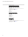
8-3 Description of Commands • • • • • • • • • • • • • • • • • • • • • • • • • • • • • • • • • • • • • • • • • • • • • • • • • 8-7
■ Read command (03H) • • • • • • • • • • • • • • • • • • • • • • • • • • • • • • • • • • • • • • • • • • • • • • • • • 8-7
■ Write command (10H) • • • • • • • • • • • • • • • • • • • • • • • • • • • • • • • • • • • • • • • • • • • • • • • • • 8-9
8-4 Specifications Common with CPL Communications Function• • • • • • • • • • • • 8-11
■ Definition of word addresses • • • • • • • • • • • • • • • • • • • • • • • • • • • • • • • • • • • • • • • • • 8-11
■ Numeric representation • • • • • • • • • • • • • • • • • • • • • • • • • • • • • • • • • • • • • • • • • • • • • • 8-11
■ RS-485 driver control timing specifications • • • • • • • • • • • • • • • • • • • • • • • • • • 8-11
Chapter 9. LIST OF COMMUNICATION DATA
■ List of communication data
• • • • • • • • • • • • • • • • • • • • • • • • • • • • • • • • • • • • • • • • • • •
9-1
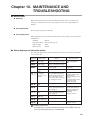
Chapter 10. MAINTENANCE AND TROUBLESHOOTING
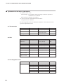
■ Maintenance • • • • • • • • • • • • • • • • • • • • • • • • • • • • • • • • • • • • • • • • • • • • • • • • • • • • • • • • • • 10-1
■ Alarm displays and corrective action • • • • • • • • • • • • • • • • • • • • • • • • • • • • • • • • • 10-1
■ Operation in case of PV input failure • • • • • • • • • • • • • • • • • • • • • • • • • • • • • • • • • 10-2
xi
Chapter 11. CALIBRATION
■
■
■
■
■
Starting the calibration • • • • • • • • • • • • • • • • • • • • • • • • • • • • • • • • • • • • • • • • • • • • • • • 11-1
Exiting the calibration • • • • • • • • • • • • • • • • • • • • • • • • • • • • • • • • • • • • • • • • • • • • • • • • 11-1
Cautions before starting the calibration • • • • • • • • • • • • • • • • • • • • • • • • • • • • • • 11-2
Measuring instruments required for calibration • • • • • • • • • • • • • • • • • • • • • • 11-2
Calibration procedures • • • • • • • • • • • • • • • • • • • • • • • • • • • • • • • • • • • • • • • • • • • • • • • 11-2
Chapter 12. DISPOSAL
Chapter 13. SPECIFICATIONS
■ Specifications • • • • • • • • • • • • • • • • • • • • • • • • • • • • • • • • • • • • • • • • • • • • • • • • • • • • • • • • 13-1
■ Accessories and optional parts • • • • • • • • • • • • • • • • • • • • • • • • • • • • • • • • • • • • • • • 13-5
Appendix
Glossary • • • • • • • • • • • • • • • • • • • • • • • • • • • • • • • • • • • • • • • • • • • • • • • • • • • • • • • • • • Appendix-1
Index
xii
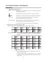
Conventions Used in This Manual
The following conventions are used in this manual:
Handling Precautions
: Handling Precautions indicate items that the user should pay attention to
when handling the SDC15.
: This indicates the item or page that the user is requested to refer to.
Note
: Notes indicate useful information that the user might benefit by knowing.
(1), (2), (3)
: The numbers with the parenthesis indicate steps in a sequence or
indicate corresponding parts in an explanation.
[para], [mode] etc.
: These indicate keys on the keyboard of this unit, and messages and
menus that appear on the personal computer screen.
>>
: This indicates the operation results and the status after operation.
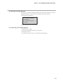
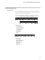
● Numeric value and character display on LED
Numeric values The 7-segment LED expresses numeric values as follows:
0
1
2
3
4
5
6
7
8
9
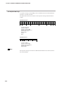
Alphabetical characters
The 7-segment LED expresses alphabetical characters shown below.
There are some alphabetical characters, which are not displayed on
the LED.
A
B
C
D
E
a
b
c
d
e
F
G
H
I
J
f
g
h
i
j
K
L
M
N
O
k
l
m
n
o
P
Q
R
S
T
p
q
r
s
t
U
V
Y
Z
–
u
v
y
z
Handling Precautions
As shown above, numeric value "2" and alphabetic character "Z" are
shown in the same manner.
Accordingly, numeric value "5" and alphabetic character "S", as well as
numeric value "9" and alphabetic character "Q" are also shown in the
same manner.
xiii
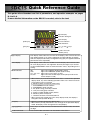
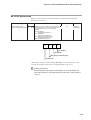
Quick Reference Guide
This guide offers flowchart and list of parameters, and operation examples on pages
D-1 to D-8.
If more detailed information on the SDC15 is needed, refer to the text.
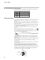
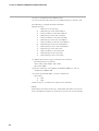
Upper display
Indicators during AT
Lower display
[mode] key
Various indicators
Mode indicators
[para] key
[ ], [ ], and [ ] keys
Loader connector
(bottom panel)
Lower display
This display shows either the SP/MV/CT or the display value and set value
for each displayed item. The rightmost decimal point lights up or flashes
to show RUN/READY mode or communications status, depending on the
setting.
Mode indicators
rdy:
man:
ev1, ev2, ev3:
ot1, ot2:
[mode] key
• When this key is pressed and held for more than 1 second in the operation
display mode, any of the following operations from 0 to 7 which have been
set previously can be executed:
0 : Mode key does not operate (Initial value)
1 : AUTO/MANUAL mode selection
2 : RUN/READY mode selection
3 : AT (Auto Tuning) start/stop selection
4 : LSP (Local SP) group selection
5 : Release all DO (Digital Output) latches
6 : Mode key does not operate
7 : ON/OFF selection of communication DI
• When pressing the [mode] key in the setup display mode, the display is
changed to the operation display
[para] key
• This key is used to change the display item.
• When this key is kept pressed for 2 sec. or longer in the operation display
mode, the display is then changed to the setup display
[<], [ ], [ ] keys
These keys are used to increase or decrease the numeric value, or to shift
the digit.
Loader connector
The Smart Loader connector is on the bottom of the SDC15.
<
This display shows either the PV value or the display value and set value for
each displayed item. If an alarm is triggered, the normal display and alarm
code are displayed alternately. During auto tuning (AT), the rightmost decimal
point flashes twice repeatedly.
<
Upper display
Lights when READY (RUN mode if not lit)
Lights when MANUAL (AUTO mode if not lit)
Lights when event relays are ON
Lights when the control output is ON (always lit when the
current output is used)
D-1
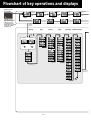
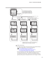
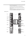
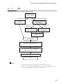
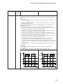
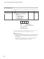
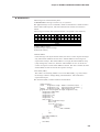
Flowchart of key operations and displays
When the power
is turned ON
PV value (3)
LSP group
number
[para] key
SP value
SP value
2
Manipulated
variable
Heat manipulated
variable
Cool manipulated
variable
MV value
MV value
MV value
1
(1)
Upper and lower displays
remain off for 6s after
power ON. Each mode
indicator lights sequentially,
and then the operation
display appears.
2-second press
+ hold of
[para] key
[mode]
[SP]
[Event]
[PID]
[Parameter] [Extended tuning]
A
(AUTO)
(MANUAL)
For change
from MANUAL
to AUTO
For change
from AUTO
to MANUAL
to
2
to
1
[para] key
(3)
[para]
key
to
D-2
A
2-second
press + hold
of [para] key
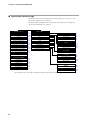
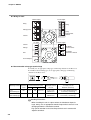
O Some items are not displayed depending on the availability of optional functions, model number, display setup
(C73 to C78) and display level (C79).
O Pressing [para] while changing settings has the effect of canceling and moving to the next item.
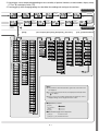
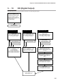
Operation displays
PV value
AT progress
value
2-second press
+ hold of
[para] key
CT1
CT2
Current
value
Current
value
Internal event 1
main setting
Internal event 1
sub setting
Timer remaining
time
Setting value
Setting value
Internal event 1
delay time
[para] key
Timer remaining
time 3
Internal event 3
sub setting
Internal event 3
main setting
Timer remaining
time 2
Internal event 2
sub setting
Internal event 2
main setting
Internal event 3
delay time
Setting value
Setting value
Internal event 2
delay time
Setting value
Setting value
to
Setting displays
2
[Event configuration] [DI assignment] [DO assignment] [User function]
[Setup]
[Lock] [Instrument information]
(2)
Communications
Key operations and displays
SP
Continuous outputs
Control actions
Analog input
B
[para] key
to
B
Notes:
(1) The parameters and numerical values registered as user functions UF
are displayed.
(2) If no key is pressed for 3 minutes, the display automatically returns
to 2 , PV display.
(3) If the [<] key is pressed while holding down the [para] key, various
displays/settings can be navigated in reverse order.
■ Explanation of arrows
[para] key
:
2-second press
+ hold of
[para] key
:
■ Movement through each setup menu
• [para] key
Forward movement
• [para] key + [<] key Backward movement
D-3
Gray letters
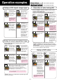
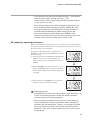
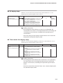
Outlined letters
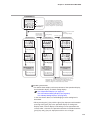
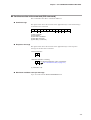
Setup of PV input range type
Start from the
operation display
(if necessary
press [mode] once
to get the operation display).
Press and hold
[para] for more
than 2s to get the
parameter setup
display. a--M is
shown on the
upper display.
If no sensor is connected,
an alarm for abnormal
PV input (any one from
AL0 1 to AL 1 1) may
appear on the upper
display.
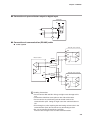
In case of ON/OFF
control, r--r appears
on the upper display.
: Items during operation
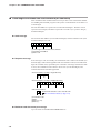
Execution of auto tuning (AT)
AT forces ON/OFF of the MV a number of times (a limit
cycle) to calculate PID values.
Check that this operation does not create any problems
for the associated equipment before executing AT.
<
Start from the
operation display
(if necessary
press [mode]
once to get the
operation display).
Press and hold
[para] for more
than 2s to get the
parameter setup
display. a--M is
shown on the
upper display.
Press [para] twice.
The upper display
says at and the
lower display says
at.Of.
When [ ] or [ ] is
pressed, at.Of
flashes.
If the control method is
ON/OFF control and if
Bit 3 (AT stop/start
display) of the mode
display setting (C73) is
set to "disabled: 0,"
nothing is displayed.
<
[Press [ ] once.
The lower display
starts to flash
at.On.
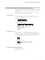
Setup of event operation type
Press and hold
[para] for more
than 2s to get the
parameter setup
display. a--M is
shown on the
upper display.
Press and hold
[para] for more
than 2s again to
get the setup
setting display.
The current set
value for C0 1
(PV input range
type) is displayed.
Press [para]
repeatedly to get
e 1.c 1 on the upper
display. 0 is
displayed on the
lower display.
Start from the
operation display
(if necessary
press [mode] once
to get the operation display).
Check that the
operation display
is displaying the
SP.
(If not, press [para]
repeatedly until the
SP is displayed.)
When the [<], [ ]
or [ ] key is pressed, the rightmost
digit on the lower
display flashes and
the SP can be
changed to the
desired value.
In this case, the
flashing of the
numerical value
implies that it is not
yet set. A numerical
setting that is being
changed flashes
the same way.
If no key is pressed
for more than 2s,
the displayed value
is set and the
display changes
from flashing to
continuously lit.
<
0 on the lower display
indicates that the event
operation type is set to
"none."
<
<
<
<
If no key is pressed
for more than 2s,
at.ON remains steadily lit and AT begins.
During AT, the rightmost decimal point
flashes twice repeatedly. (When AT
is done, the light
goes off and the
new PID values go
into effect.)
Setup of SP value
When the [ ] or [ ] key is pressed, the rightmost
digit on the lower display flashes. Change the
flashing digit to 4 by pressing [ ] or [ ].
If no key is pressed for more than 2s, the
displayed value is set and the display changes
from flashing to continuously lit.
<
Flashing occurs only in
RUN and AUTO modes,
if there is no PV input
abnormality.
Also, if "AT stop/start" is
selected for DI assignment, the display does
not blink and no change
can be made.
During the AT process, if the mode is changed to
READY or MANUAL, if PV input is faulty, or if a power
failure occurs, AT stops automatically without changing
the PID values.
AT can also be stopped by changing the setting from
At.ON to At.OF (return to step 3 above).
In this example, the event 1 operation type is set to
deviation high limit.
Start from the
operation display
(if necessary
press [mode]
once to get the
operation display).
<
When the [<], [ ]
or [ ] key is
pressed, the rightmost digit on the
lower display
flashes. If no key
is pressed for
more than 2s after
changing to the
desired value in
the PV input range
list, the display
changes from
flashing to continuously lit, and
the displayed
value is now set.
<
Press and hold
[para] for more
than 2s again to
get the setup
setting display.
The current set
value for C0 1
(PV input range
type) is displayed.
: Items before operation
<
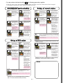
Operation examples
4 on the lower display indicates that the event operation type is
set for deviation high limit.
Similarly, use e2.C 1 to set the event 2 operation type, and
use e3.C 1 for event 3.
If an SP limit is in effect, the numerical
value cannot be changed to a value
above the limit. The SP limit must be
changed first.
D-4
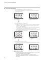
If the [mode] key is
pressed when the
display is flashing, the
status returns to that of
step 1.
• For step numbers indicated in red like 4 , the following precaution applies:
If the key lock is set, the numerical value does not flash, and the value cannot be changed.
To change a numerical value, cancel the key lock first.
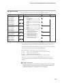
RUN/READY mode selection
>
>
When [ ] or [ ] is
pressed, run (or
rdy) on the lower
display flashes.
Press and hold
[para] for more
than 2s to get the
parameter setup
display. a--M is
shown on the
upper display.
In case of ON/OFF
control, r--r appears
on the upper display.
Press [para]
repeatedly to get
e 1 on the upper
display. The lower
display says 0.
When [<], [ ] or
[ ] is pressed, the
rightmost digit on
the lower display
flashes, and can
be changed to the
desired value for
the event.
In this case, the
flashing of the
numerical value
implies that it is
not yet set.
A numerical setting that is being
changed flashes
the same way.
When [ ] or [ ] is
pressed, the lower
display flashes.
0 on the lower display
indicates that the event
main set value is "zero."
If the DI assignment is
set to "RUN/READY
selection," the display
does not flash and no
change can be made.
If no key is pressed
for more than 2s,
the displayed value
is set and the
display changes
from flashing to
continuously lit.
>
>
The current mode is
indicated by run for
RUN mode or rdy for
READY mode.
Start from the
operation display
(if necessary press
[mode] once to get
the operation
display).
>
Press the [para]
key once. The
upper display says
r--r and the lower
display says rdy
(or run).
Press and hold
[para] for more
than 2s to get the
parameter setup
display. a--M is
shown on the
upper display.
>
Start from the
operation display
(if necessary press
[mode] once to get
the operation
display).
Setup of event value
If no key is pressed for more than 2s, the displayed
value is set and the display changes from flashing
to continuously lit.
If the [mode] key is pressed when the display is flashing, the status
returns to that of step 1.
Setup of PID value
Similarly, use e2 to set a value for event 2, and e3 to set
a value for event 3.
If the control method is
"ON/OFF control,"
nothing is displayed.
<
>
5 on the lower display
indicates that the current
set value for event
hysteresis is 5.
<
When [<], [ ] or
[ ] is pressed, the
rightmost digit on
the lower display
flashes, and can
be changed to the
desired value for
the proportional
band.
In this case, the
flashing of the
numerical value
implies that it is
not yet set. A
numerical setting
that is being
changed flashes
the same way.
When [<], [ ] or
[ ] is pressed, the
rightmost digit on
the lower display
flashes, and can
be changed to the
desired value for
hysteresis.
If no key is pressed
for more than 2s,
the displayed value
is set and the
display changes
from flashing to
continuously lit.
<
Press [para]
repeatedly to get
p-1 (for proportional band) on
the upper display.
The value set for
p-1 is displayed on
the lower display.
To set hysteresis
as well, press
[ ] twice or press
[ ] repeatedly to
get e 1.hy on the
upper display and
5 on the lower
display.
<
Press and hold
[para] for more
than 2s to get the
parameter setup
display. a--M is
shown on the
upper display.
>
Start from the
operation display
(if necessary press
[mode] once to
get the operation
display).
Similarly, use e2.hy to set a hysteresis value for event 2,
and e3.hy to set a hysteresis value for event 3.
Memo
The proportional band
can be set in a range
from 0.1 to 999.9%.
If no key is pressed for more than 2s, the
displayed value is set and the display changes
from flashing to continuously lit.
If the [mode] key is pressed when the display is flashing, the status
returns to that of step 1.
Similarly, use i-1 to set the integral time (0 to 9999s),
and d-1 to set the derivative time (0 to 9999s).
D-5
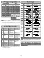
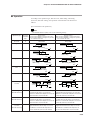
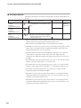
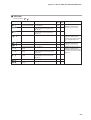
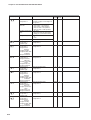
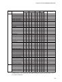
List of parameter
: Essential parameters for PV measurement and control
: Basic parameters
: Required parameters when using optional functions
Et
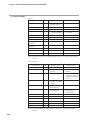
List of operation displays
E2
Numeric value
E2. Sb
Numeric value
t2. --(Display example)
Numeric value
E3
Numeric value
E3. Sb
Numeric value
t3. --(Display example)
Numeric value
SP(Target value)
Contents
SP low limit to SP high limit
Initial value Setting value
0
LSP group number
1 to LSP system group (Max. 4)
(1st digit=the right end digit)
MV (Manipulated Variable) -10.0 to +110.0%
Setting is enabled in MANUAL mode
(Numeric value flashed)
Heat MV (Manipulated Variable) Setting is disabled.
-10.0 to +110.0%
Cool MV (Manipulated Variable)
1
AT progress display
Setting is disabled.
(1st digit=the right end digit)
CT current value 1
Setting is disabled.
–
JF.Ov
St.SA
St.Sb
St.Hb
St.ud
–
–
–
CT current value 2
Setting is disabled.
–
Internal Event 1 main setting
-1999 to +9999U or 0 to 9999U
0
StUP
Internal Event 1 sub setting
Internal Event 1 remaining Setting is disabled.
L
time
" ", is displayed at the right end digit when using
the ON delay time, and "L" , the OFF delay time.
Internal Event 2 main setting Same as Internal Event 1 main setting
0
Internal Event 2 sub setting Same as Internal Event 1 sub setting
0
Internal Event 2 remaining Same as Internal Event 1 remaining time
time
Internal Event 3 main setting Same as Internal Event 1 main setting
0
Internal Event 3 sub setting Same as Internal Event 1 sub setting
Internal Event 3 remaining Same as Internal Event 1 remaining time
time
–
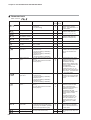
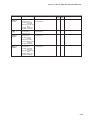
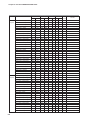
Item
PV input range type
Temperature unit
● Cold junction compensation
Decimal point position
0
C05
C06
C07
C08
C09
PV input range low limit
PV input range high limit
● SP low limit
● SP high limit
● PV square root extraction dropout
–
C 14
–
Contents
Initial value Setting value
AUTO: AUTO mode MAN: MANUAL mode
AUTO
RUN: RUN mode RDY: READY mode
RUN
At. OF: AT stop At. ON: AT start
AT stop
Lt. ON: Latch continue Lt. OF: Latch release Latch continue
dI . OF: OFF dI . On: ON
OFF
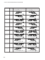
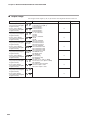
[SP bank]
Item
Contents
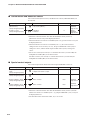
Internal Event 1 to 5 main setting -1999 to +9999 or 0 to 9999
Internal Event 1 to 5 sub setting (The decimal point position may vary so that it
meets the operation type of the internal event)
Internal Event 1 to 5 hysteresis 0 to 9999
E 1.Hy to E5.Hy
(The decimal point position may vary so that it
meets the operation type of the internal event)
E 1.On to E5.On ● Internal Event 1 to 5 ON delay time 0.0 to 999.9 or 0 to 9999
E 1.Of to E5.Of ● Internal Event 1 to 5 OFF delay time
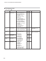
Display
P- 1
I-1
d- 1
rE- 1
OL- 1
OH- 1
P- 1C
I - 1C
d- 1C
OL. 1C
OH. 1C
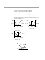
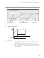
SP Time proportional output
PV
Control
PARA
Initial value
0
Setting value
5
0
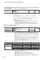
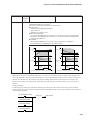
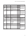
[PID bank]
●
●
●
●
Item
Proportional band (PID1)
Integral time (PID1)
Derivative time (PID1)
Manual reset (PID1)
MV low limit (PID1)
MV high limit (PID1)
Proportional band (cool) (PID1)
Integral time (cool) (PID1)
Derivative time (cool) (PID1)
Output low limit (cool) (PID1)
Output high limit (cool) (PID1)
Contents
Initial value
0.1 to 999.9%
5.0
0 to 9999s (No integration control action when set at "0")
120
0 to 9999s (No derivative control action when set at "0")
30
-10.0 to +110.0%
50.0
-10.0 to +110.0%
0.0
-10.0 to +110.0%
100.0
0.1 to 999.9%
5.0
0 to 9999s (No integration control action when set at "0")
120
0 to 9999s (No derivative control action when set at "0")
30
-10.0 to +110.0%
0.0
-10.0 to +110.0%
100.0
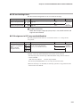
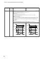
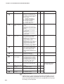
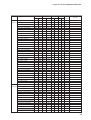
Item
Control method
At. OL
At. OH
dI FF
OFFS
FL
rA
bI
CyU
Cy
CyU2
Cy2
tP.ty
MV low limit at AT
MV high limit at AT
Differential (for ON/OFF control)
ON/OFF control action point offset
PV filter
PV ratio
PV bias
Time proportional cycle unit 1
Time proportional cycle 1
Time proportional cycle unit 2
Time proportional cycle 2
Time proportional cycle mode
●
●
●
●
●
● SP up ramp
● SP down ramp
Contents
Initial value
0: ON/OFF control 1: Fixed PID
0 or 1
2: ST(Self-tuning)
-10.0 to +110.0%
0.0
-10.0 to +110.0%
100.0
0 to 9999U
5
-1999 to +9999U
0
0.0 to 120.0s
0.0
0.001 to 9.999
1.000
-1999 to +9999U
0
0 to 3 *1
0
5 to 120s or 1 to 120s *2
10 or 2
0 to 3 *1
0
5 to 120s or 1 to 120s *2
10 or 2
0: Controllability aiming type
0 or 1
1: Operation end service life aiming type(Only ON/
OFF operation within Time proportional cycle)
0.0 to 999.9U(No ramp when set at "0.0U")
0.0
0.0
*1 0: 1s unit 1: Cycle fixed at 0.5s 2: Cycle fixed at 0.25s
3: Cycle fixed at 0.1s
*2 5 to 120s when output includes the relay output
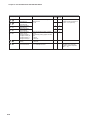
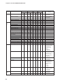
Control action (Direct/Reverse)
C 15
● Output operation at PV alarm
C 16
C 17
C 18
C 19
C20
C2 1
C22
C26
C27
C28
C29
C30
C32
C36
C37
C38
C39
C40
C4 1
C42
C43
●
●
●
●
●
●
●
Output at PV alarm
Output at READY (Heat)
Output at READY (Cool)
Output operation at changing AUTO/MANUAL
Preset MANUAL value
Initial output type of PID control
Initial output of PID control
Heat/Cool control
● Heat/Cool selection
Heat/Cool control dead zone
● Heat/Cool control change point
LSP system group
● SP ramp unit
CT1 operation type
CT1 output
CT1 measurement wait time
CT2 operation type
CT2 output
CT2 measurement wait time
Control output 1 range
Control output 1 type
C44
C45
C46
C47
C48
C49
C50
C5 1
C64
Control output 1 scaling low limit
Control output 1 scaling high limit
Control output 1 MV scaling
Control output 2 range
Control output 2 type
Control output 2 scaling low limit
Control output 2 scaling high limit
Control output 2 MV scaling
CPL/MODBUS
C65
C66
C67
C68
C69
C70
C7 1
C72
Station address
Transmission speed (bps)
Data format (Data length)
Data format (Parity)
Data format (Stop bit)
● Response time-out
● Key operation type
[mode] key function
C73
● MODE display setup
(Sum of the weighting)
C74
● PV/SP display setup
(Sum of the weighting)
C75
● MV display setup
(Sum of the weighting)
C76
● EV display setup
(Operation display)
C77
● Timer remain time display setup
(Operation display)
C78
● CT display setup
(Operation display)
User level
Setting value
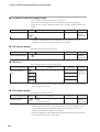
[Parameter bank]
Display
CtrL
SPU
SPd
Setting value
[Event bank]
Display
E 1 to E5
E 1.Sb to E5.Sb
PI D
Initial value
0
Communication
Ev
Contents
SP low limit to SP high limit
Continuous output
Display
Item
SP- 1 to SP-4 SP of LSP 1 group to 4 group
Setting value
U: Unit Maximum unit of Industrial volume in PV range (°C, Pa,L/min, etc.)
Key operation • display
SP
Initial value
1
0.30
0.0
1.00
1.00
1.00
0
Setting value
0
10.0
0.50
1.00
0
[Setup bank]
Display
C0 1
C02
C03
C04
[Mode bank]
Item
AUTO/MANUAL
RUN/READY
AT stop/start
Release all DO latches
Communication DI1
●
●
●
●
Contents
0: Normal 1: Immediate response 2: Stable *1
0.00 to 10.00
0.0 to 999.9
0.00 to 99.99
0.00 to 99.99
0.00 to 99.99
0: PID(Conventional PID)
1: Ra-PID(High-performance PID)
Just-FiTTER oversheet suppression factor 0 to 100
ST step execution resolution band 0.0 to 99.99
ST step setting band
0.0 to 10.00
ST hunting setting band
0.0 to 10.00
ST step ramp change
0: ST is executed when the PV moves up or down.
1: ST is executed only when the PV moves up.
List of setup setting displays
SP
Display
A--M
r--r
At
do Lt
C. dI 1
●
●
●
●
●
Item
AT type
Just-FiTTER setting band
SP lag constant
Proportional band tuning factor at AT
Integral time adjust at AT
AT Derivative time adjust
Control algorithm
*1 Normal = Standard control characteristics, Immediate response = Control characteristics that respond immediately to external disturbance, Stable = Control characteristics having less up/down fluctuation of PV
List of parameter setting displays
MOdE
[Extended tuning bank]
–
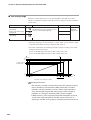
Analog input
HEAt
Numeric value
COOL
Numeric value
PV
At 1 (Display example)
Ct 1
Numeric value
Ct2
Numeric value
E1
Numeric value
E 1. Sb
Numeric value
t 1. --(Display example)
Numeric value
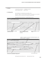
Item
Control action
Display
Upper display: PV
Lower display: SP
PV
SP
LSP 1 (Display example)
LSP
PV
MV
Display
At.ty
JF.bd
SP.LG
At-P
At-I
At-d
Ctr.A
C79
C80
● Communication monitor
display
C90
C9 1
C92
C93
●
●
●
●
Number of CT1 turns
Number of CT1 power wire loops
Number of CT2 turns
Number of CT2 power wire loops
*1 Not available for thermocouples.
D-6
Contents
Initial value
Setting value
For details, refer to the PV Input Range Table Depending on Model No.
0: Celsius (°C) 1: Fahrenheit (°F)
0
0: Performed (internal) 1: Not performed (external)
0
0
0: No decimal point
1 to 3: 1 to 3 digits below decimal point *1
When the PV input type is DC voltage/DC current,
0
-1999 to +9999U
1000
PV input range low limit to PV input range
–
high limit
–
0.0 to 100.0% (PV square root extraction
0.0
is not performed when set at "0.0".)
0: Heat control (Reverse action)
0
1: Cool control (Direct action)
0: Control calculation is continued.
0
1: Output at PV alarm is output.
-10.0 to +110.0%
0.0
-10.0 to +110.0%
0.0
-10.0 to +110.0%
0.0
0: Bumpless transfer 1: Preset
0
-10.0 to +110.0%
0.0 or 50.0
0: Auto 1: Not initialized 2: Initialized
0
-10.0 to +110.0%
0.0 or 50.0
0: Not used 1: Used
0
0: Normal 1: Energy saving
0
-100.0 to +100.0%
0.0
-10.0 to +110.0%
50.0
1 to 4
1
0: 0.1U/s 1: 0.1U/min 2: 0.1U/h
1
0: Heater burnout detection 1: Current value measurement
0
0 to 1: Control output 1 to 2, 2 to 4: Event output 1 to 3
0
30 to 300ms
30
Same as CT1
0
Same as CT1
0
Same as CT1
30
1: 4 to 20mA 2: 0 to 20mA
1
0: MV 1: Heat MV 2: Cool MV 3: PV
0
4: PV before ratio, bias, and filter
5: SP 6: Deviation 7: CT1 current value
8: CT2 current value 10: SP+MV 11: PV+MV
-1999 to +9999U
0.0
100.0
0 to 9999 (Valid when control output 1 type is 10 or 11)
200
Same as control output 1
1
Same as control output 1
3
Same as control output 1
0
Same as control output 1
1000
Same as control output 1
200
0: CPL 1: MODBUS (ASCII format)
0
2: MODBUS (RTU format)
0 to 127 (Communication is disabled when set at "0".)
0
0: 4800 1: 9600 2: 19200 3: 38400
2
0: 7 bits 1: 8 bits
1
0: Even parity 1: Odd parity 2: No parity
0
0: 1 bit 1: 2 bits
0
1 to 250ms
3
0: Standard type 1: Special type
0
0: Invalid 1: AUTO/MANUAL selection
0
2: RUN/READY selection 3: AT Stop/Start
4: LSP group selection 5: Release all DO latches
6: Invalid 7: Communication DI1 selection 8: Invalid
Bit 0: AUTO/MANUAL display (Enabled: +1)
255
Bit 1: RUN/READY display (Enabled: +2)
Bit 3: AT Stop/Start display (Enabled: +8)
Bit 4: Release all DO latches display (Enabled: +16)
Bit 5: Communication DI1 ON/OFF display (Enabled: +32)
Other invalid setting, 0, +4, +64, +128
Bit 0: PV display (Enabled: +1)
15
Bit 1: SP display (Enabled: +2)
Bit 2: LSP group number display (Enabled: +4)
Other invalid setting, 0, +8
Bit 0: MV display (Enabled: +1)
15
Bit 1: Heat MV/cool MV display (Enabled: +2)
Bit 3: AT progress display (Enabled: +8)
Other invalid setting: 0, +4
0: Not displayed
0
1: Set value of Internal event 1 is displayed
2: Set values of Internal event 1 to 2 are displayed
3: Set values of Internal event 1 to 3 are displayed
0: Not displayed
0
1: Internal event 1 is displayed
2: Internal event 1 to 2 is displayed
3: Internal event 1 to 3 is displayed
1
0: Not displayed 1: CT1 current value is displayed
2: CT1 to 2 current values are displayed
0
0: Simple configuration 1: Standard configuration
2: High function configuration
0: Not used
0
1: Flashing while data is sending through
RS-485 communication.
2: Flashing while data is receiving through
RS-485 communication
3: Logical OR of all DI statuses
4: Flashing in READY mode
0: 800 turns 1 to 40: CT turns divided by 100
8
0: 1 time 1 to 6: Number of times
1
0: 800 turns 1 to 40: CT turns divided by 100
8
0: 1 time 1 to 6: Number of times
1
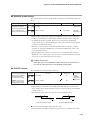
• Items marked ● in the tables are displayed in standard and/or high function configuration.
• To change a user level, refer to
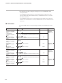
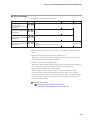
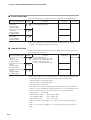
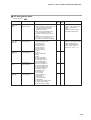
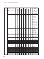
Item
Internal event 1 to 5 Configuration 1
Operation type
E 1.C2 to E5.C2
Internal event 1 to 5 Configuration 2
Operation type
1st digit: Direct/Reverse
2nd digit: Standby
3rd digit: EVENT state at READY
4th digit: Undefined
E 1.C3 to E5.C3 ● Internal event 1 to 5 Configuration 3
1st digit: Controller alarm OR
2nd digit: Special OFF setup
3rd digit: Delay unit
4th digit: Undefined
di
Contents
Refer to event type (see page 8)
The digits are determined to 1st, 2nd, 3rd,
and 4th digit from the right end.
0: Direct 1: Reverse
0: None 1: Standby 2: Standby + Standby at SP change
0: Continue 1: Forced OFF
0
The digits are determined to 1st, 2nd, 3rd,
and 4th digit from the right end.
0: None 1: Alarm direct + OR operation
2: Alarm direct + AND operation
3: Alarm reverse + OR operation
4: Alarm reverse + AND operation
0: As usual
1: When the event set value (main setting)
is 0, the event is "OFF".
0: 0.1s 1: 1s 2: 1min
0
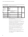
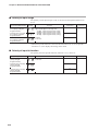
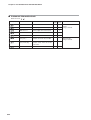
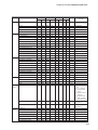
Item
Internal contact 1 to 3
Operation type
dI 1.2 to dI 3.2 ● Internal contact 1 to 3
Input bit function
dI 1.3 to dI 3.3 ● Internal contact 1 to 3
Input assign A
dI 1.4 to dI 3.4 ● Internal contact 1 to 3
Input assign B
dI 1.5 to dI 3.5 ● Internal contact 1 to 3
Input assign C
dI 1.6 to dI 3.6 ● Internal contact 1 to 3
Input assign D
dI 1.7 to dI 3.7 ● Internal contact 1 to 3
Polarity A to D
1st digit: Polarity A
2nd digit: Polarity B
3rd digit: Polarity C
4th digit: Polarity D
dI 1.5 to dI 3.5 ● Internal contact 1 to 3 Polarity
dI 1.9 to dI 3.9 ● Internal contact 1 to 3
Event channel def.
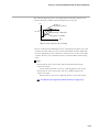
Ot 1.5 to Ot2.5 ●
Ev 1.5 to Ev3.5
Ot 1.6 to Ot2.6 ●
Ev 1.6 to Ev3.6
Ot 1.7 to Ot2.7 ●
Ev 1.7 to Ev3.7
Ot 1.8 to Ot2.8 ●
Ev 1.8 to Ev3.8
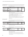
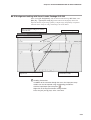
C.LOC
L.LOC
PASS
PS 1A
PS2A
PS 1b
PS2b
Subtract 2000 from the year.
Example: "3" means the year 2003.
Month + day divided by 100.
Example: "12.01" means the 1st day of December.
Initial value Setting value
0
–
–
–
–
–
–
–
0
Precaution for setup
0
• The type of auto tuning can be changed by changing the value of At.ty (AT
type) in the extended tuning bank. Set it to match the control characteristics.
0
0
0: Direct 1: Reverse
0: Every Internal Event
1 to 5: Internal Event No.
Initial value Setting value
0
0
2: Contact 1
3: Contact 2
4: Contact 3
0
0
0
0
0
0
0
0
0
Contents
0: Default output 1 to 2: MV1 to 2
3 to 6: Function 1 to 4
0: Normally opened 1: Normally closed
2 to 6: Internal Event 1 to 5
7 to 13: Undefined 14 to 15: MV1 to 2
16 to 17: Undefined 18 to 19: DI1 to 2
20 to 25: Undefined
Output assign B (Control output 1 to 2, 26 to 28: Internal Contact 1 to 3
Event output 1 to 3)
29 to 33: Undefined 34 to 37: DI1 to 4
38: MANUAL 39: READY 40: Undefined
Output assign C (Control output 1 to 2, 41: AT running 42: During SP ramp 43: Undefined
Event output 1 to 3)
44: Alarm occurs 45: PV alarm occurs
46: Undefined 47: Mode key pressing status
Output assign D (Control output 1 to 2, 48: Event output 1 status
Event output 1 to 3)
49: Control output 1 status
Control output 1 to 2, Event output The digits are determined to 1st, 2nd, 3rd,
1to 3 Polarity A to D
and 4 th digit from the right end.
1st digit: Polarity A
0: Direct 1: Reverse
2nd digit: Polarity B
3rd digit: Polarity C
4the digit: Polarity D
Polarity (Control output 1 to 2, 0: Direct 1: Reverse
Event output 1 to 3)
Latch (Control output 1 to 2, 0: None 1: Latch (Latch at ON)
Event output 1 to 3)
2: Latch (Latch at OFF except for initialization
at power ON)
Initial value Setting value
0
14: Output 1
15: Output 2
2: Event 1
3: Event 2
4: Event 3
0
0
0
0
0
0
0
0
0
[User function bank]
Item
● User function 1 to 8
Contents
–
Initial value Setting value
–
[Lock bank]
Item
Key lock
● Communication lock
● Loader lock
Password display
Password 1A
Password 2A
Password 1B
Password 2B
Contents
Initial value Setting value
0: All settings are possible
0
1: Mode, event, operation display, SP, UF, lock,
manual MV, [mode] key can be set
2: Operation display, SP, UF, lock,
manual MV, [mode] key can be set
3: UF, lock, manual MV, [mode] key can be set
0: read/write enabled 1: read/write disabled
0
0: read/write enabled 1: read/write disabled
0
0 to 15(5: Password 1A to 2B display)
0
0000 to FFFF (Hexadecimal value)
0000
0000 to FFFF (Hexadecimal value)
0000
0000 to FFFF (Hexadecimal value)
0000
0000 to FFFF (Hexadecimal value)
0000
D-7
This controller's user level can be set to 1 of 3 types in setup
C79.
The number of possible displays and settings decreases
according to the user level: high function > standard > simple. All items are displayed when high function is selected.
If necessary press
[mode] once to
change to the
operation display.
Next, press and
hold [para] for
more than 2s to
get the parameter
setup display. a--M
or r--r appears
on the upper display.
Press and hold
[para] for more
than 2s again to
display c 01 on the
upper display.
Press [para]
repeatedly to
change the upper
display to c 79
(user level).
When [<], [ ] or
[ ] is pressed, the
lower display
flashes and can be
changed to the
desired numerical
value. Then, if no
key is pressed for
more than 2s, the
displayed value is
set and the display
changes from
flashing to continuously lit.
<
Display
LOC
I d08
Contents
0: SDC15
XX. XX (2 digits after decimal point)
XX. XX (2 digits after decimal point)
Changing the user level
Ot 1.4 to Ot2.4 ●
Ev 1.4 to Ev3.4
LOC
I d07
Item
ROM ID
ROM Version 1
ROM Version 2
Loader information
EST information
Manufacturing date code
(year)
● Manufacturing date code
(month, day)
● Serial No.
●
●
●
●
●
●
[DO assignment bank]
Ot 1.3 to Ot2.3 ●
Ev 1.3 to Ev3.3
Display
UF- 1 to UF-8
0
0
0
0
[Instrument information bank]
Display
I d0 1
I d02
I d03
I d04
I d05
I d06
Memo
Contents
0: No function 1: LSP group selection (0/+1)
2: LSP group selection (0/+2)
3: LSP group selection (0/+4) 4: Invalid
5: Invalid 6: Invalid 7: RUN/READY selection
8: AUTO/MANUAL selection
9: LSP/RSP selection 10: AT Stop/Start
11: ST disabled/enabled
12: Control action direct/reverse
13: SP Ramp enabled/disabled
14: PV Hold 15: PV Maximum value hold
16: PV Minimum value hold 17: Timer Stop/Start
18: Release all DO latches (Continue/Release)
19: Invalid 20: Invalid
0: Not used (Default input)
1: Function 1 ((A and B) or (C and D))
2: Function 2 ((A or B) and (C or D))
3: Function 3 (A or B or C or D)
4: Function 4 (A and B and C and D)
0: Normally opened 1: Normally closed
2: DI1 3: DI2 4 to 9: Undefined
10 to 14: Internal Event 1to 5
15 to 17: Undefined
18 to 21: Communication DI1 to 4
22: MANUAL 23: READY 24: Undefined
25: AT running 26: During SP ramp 27: Undefined
28: Alarm occurs 29: PV alarm occurs
30: Undefined 31: mode key pressing status
32: Event output 1 status 33: Control output 1 status
The digits are determined to 1st, 2nd, 3rd
and 4th digit from the right end.
0: Direct 1: Reverse
Display
Item
Ot 1. 1 to Ot2. 1 ● Operation type (Control output 1 to 2,
Ev 1. 1 to Ev3. 1
Event output 1 to 3)
Ot 1.2 to Ot2.2 ● Output assign A (Control output 1 to 2,
Ev 1.2 to Ev3.2
Event output 1 to 3)
UF
Initial value Setting value
0
[DI assignment bank]
Display
di 1. 1 to dI 3. 1
dO
Id
[Event configuration bank]
Display
E 1.C 1 to E5.C 1
<
EvCF
in the lower right part of this page.
Changing the user level
0: Simple configuration
(initial value)
1: Standard configuration
2: High function configuration
PV input range table
[Thermocouple]
C01
Sensor
Set value
type
1
K
2
K
3
K
4
K
5
K
6
K
9
J
10
J
11
J
13
E
14
T
15
R
16
S
17
B
18
N
19
PL II
20
WRe5-26
21
WRe5-26
24
DIN U
25
DIN L
Range
-200 to +1200°C
0 to 1200°C
0 to 800°C
0 to 600°C
0 to 400°C
-200 to +400°C
0 to 800°C
0 to 600°C
-200 to +400°C
0 to 600°C
-200 to +400°C
0 to 1600°C
0 to 1600°C
0 to 1800°C
0 to 1300°C
0 to 1300°C
0 to 1400°C
0 to 2300°C
-200 to +400°C
-100 to +800°C
[RTD]
C01
Set value
41
42
43
44
45
46
51
52
53
54
63
64
67
68
Sensor
type
Pt100
JPt100
Pt100
JPt100
Pt100
JPt100
Pt100
JPt100
Pt100
JPt100
Pt100
JPt100
Pt100
JPt100
Operation
type
Sensor
Scaling range is
-1999 to +9999.
*2: The indicated low limit for a B thermocouple is 20°C. However, if ROM version 1
of the instrument information bank (I d02) is prior to 2.04, the value is
-180°C.
*3: Thermocouple, RTD, and DC voltage/DC current are according to PV No. type.
List of alarm code
Input failure
AL02
AL03
AL 1 1
AL70
Unit failure
AL95
AL96
AL97
AL98
AL99
Failure name
PV input failure
(Over-range)
PV input failure
(Under-range)
CJ failure
PV input failure
(RTD)
CT input failure
(Over-range)
(CT input 1 or 2,
or both)
A/D conversion
failure
Parameter failure
Cause
Sensor burnout, incorrect
wiring, incorrect PV input
type setting
Sensor burnout, incorrect
wiring, incorrect PV input
type setting
Terminal temperature is
faulty (thermocouple).
Sensor burnout, incorrect
wiring
A current exceeding the
upper limit of the display
range was measured.
The number of CT turns
or the number of CT power
wire loops is incorrectly
set, or wiring is incorrect.
A/D converter is faulty.
Power is shut-down while
the data is being set, or
data is corrupted by noise.
Adjustment data
Power is shut-down while
failure
the data is being set, or
data is corrupted by noise.
Parameter failure Data is corrupted by
(RAM area)
noise.
Adjustment data
Data is corrupted by
failure (RAM area) noise.
ROM failure
ROM (memory) is faulty.
No event
PV high
limit
0
1
Direct action
Reverse action
● shows that the ON/OFF is changed at this value.
O shows that the ON/OFF is changed at a point that
"1U" is added to this value.
● shows that the ON/OFF is changed at this value.
O shows that the ON/OFF is changed at a point that
"1U" is added to this value.
Always OFF
Always OFF
HYS
Corrective action
Check the wiring.
Set the PV input type
again.
Check the ambient
temperature.
Check the wiring.
• Use a CT with the
correct number of turns
for the display range.
• Reset the number of CT
turns.
• Reset the number of CT
power wire loops.
• Check the wiring.
Replace the unit.
• Restart the unit.
• Set the data again (set
data for AL95/97 and
adjustment data for
AL96/98.
• Replace the unit.
• Reset the unit.
• Replace the unit.
ON
ON
HYS
Main setting
Main setting
PV
PV low
limit
2
ON
PV high/
low limit
3
ON
HYS
ON
Sub-setting *
HYS
PV
HYS
ON
Main setting * Sub-setting * PV
PV
4
HYS
ON
ON
HYS
SP + Main setting PV
SP + Main setting PV
Deviation
low limit
ON
Main setting
PV
HYS
HYS
Main setting *
Deviation
high limit
PV
HYS
Main setting
5
ON
HYS
HYS
SP + Main setting
Range
type
0 to 1V
1 to 5V
0 to 5V
0 to 10V
0 to 20mA
4 to 20mA
: Initial value
*1: PL II thermocouple is a range, which has been added to the units manufactured
form July, 2003.
Alarm
code
AL0 1
Set
value
Range
-200 to +500°C
-200 to +500°C
-200 to +200°C
-200 to +200°C
-100 to +300°C
-100 to +300°C
-50.0 to +200.0°C
-50.0 to +200.0°C
-50.0 to +100.0°C
-50.0 to +100.0°C
0 to 200.0°C
0 to 200.0°C
0 to 500°C
0 to 500°C
[DC voltage/DC current]
C01
Set value
84
86
87
88
89
90
Event type
Deviation
high/low
limit
6
Deviation
high limit
(Final SP
reference)
Deviation
low limit
(Final SP
reference)
Deviation
high/low
limit
(Final SP
reference)
Heater 1
burnout/
Overcurrent
7
ON
HYS
HYS
ON
HYS
Main setting Sub-setting
PV
SP
HYS
ON
SP + Main setting
PV
PV
HYS
ON
Main setting Sub-setting
SP
PV
ON
ON
HYS
SP + Main setting PV
SP + Main setting PV
8
ON
HYS
HYS
SP + Main setting
ON
SP + Main setting
PV
PV
9
ON
HYS
HYS
ON
HYS
Main setting Sub-setting
PV
SP
ON
HYS
Main setting Sub-setting
SP
PV
16
ON
HYS
HYS
ON
HYS
Main setting *
Sub-setting *
CT1 at output ON
OFF before measuring the CT1 current value
Heater 1
shortcircuit
17
Heater 2
burnout/
Overcurrent
18
HYS
ON
ON
HYS
OFF before measuring CT1 current value
ON
HYS
Alarm
(status)
23
HYS
HYS
Sub-setting *
CT2 at output ON
OFF before measuring CT2 current value
19
ON
Main setting *
Main setitng * Sub-setting *
CT2 at output ON
Heater 2
shortcircuit
HYS
Main setting
CT1 at output OFF
OFF before measuring CT1 current value
HYS
HYS
Sub-setting *
CT1 at output ON
OFF before measuring CT1 current value
Main setting
CT1 at output OFF
ON
ON
Main setting *
OFF before measuirng CT2 current value
ON
ON
Main setting
CT2 at output OFF
OFF before measuring CT2 current value
ON if alarm occurs (alarm code AL01 to 99).
OFF in other cases.
HYS
Main setting
CT2 at output OFF
OFF before measuring CT2 current value
OFF if alarm occurs (alarm code AL01 to 99).
ON in other cases.
: initial value
*: If the main setting is greater than the sub-setting, operations are performed with the main
setting and sub-setting automatically swapped.
Event types other than the above:
Operation type
SP high limit
SP low limit
SP high/low limit
MV high limit
MV low limit
MV high/low limit
Handling precautions
• If ROM version 1 of the instrument information bank (I d02) is prior to 2.04, CT
input failure (AL 1 1) is not displayed.
D-8
Set value
10
11
12
13
14
15
Operation type
Loop diagnosis 1
Loop diagnosis 2
Loop diagnosis 3
READY (status)
MANUAL (status)
Set value
20
21
22
24
25
Operation type
Set value
During AT (status)
27
During SP ramp
28
Control action (status)
29
ST setting standby (status)
30
Timer (status)
32
Chapter 1.
1 - 1
OVERVIEW
Overview
This unit is a compact controller having a mask of 48 X 48 mm and provides the following features:
• The depth is only 60 mm, providing the excellent space-saving.
• The front panel is only 2 mm thick. This ensures the excellent thin design.
• The display panel is large. This provides excellent visibility.
• [mode] key, [para] key, and digit-shift keys are provided on the front panel.
This ensures easy setup operation.
• Various input types are available, thermocouples (K, J, E, T, R, S, B, N, PLII,
WRe5-26, DIN U, DIN L), RTDs (Pt100, JPt100), current signals (4 to
20mAdc, 0 to 20mAdc), and voltage signals (0 to 1Vdc, 1 to 5Vdc, 0 to 5Vdc,
and 0 to 10Vdc).
• For control outputs, relay, voltage pulse, and current output are provided.
Additionally, these control outputs can be combined for the 2nd control output.
• The unit can be made applicable to the heat/cool control using the 2nd control
output and/or event relay.
• ON/OFF control, fixed PID, and self-tuning control can be performed.
• In addition to the PID control, two algorithms, RationaLOOP and Just-FiTTER,
are mounted. This ensures excellent controllability.
• With optional functions, a combination among 3- or 2-event points
(independent contacts), 2-point CT input, 2-point digital input, and/or RS-485
can be selected.
• The personal computer loader port is provided as standard function. The setup
can be made easily with use of the personal computer loader.
• Use of optional Smart Loader Package (SLP-C35) makes it possible to easily
perform the read/write operation of the parameters.
In addition to the table format setup, the operation and control status can be
monitored using the trend display. This unit can be operated without use of
program on the host unit.
• The unit is applicable to the IEC directive and the CE marking is put on the
unit.
(Applicable standards: EN61010-1 and EN61326-1)
• The unit is applicable to the UL standard. (File No. E96090)
1-1
Chapter 1. OVERVIEW
■ Model selection table
The following shows the model selection table of this unit:
Basic
model No. Mounting
Control
output
Power
supply
PV input
Option
Additional
treatment
Specifications
C15
(Note 4)
T
Panel mount type
S
Socket mount type
Control output 1
Control output 2
R0
Relay contact output
None
V0
Voltage pulse output
(for SSR drive)
None
(Note 1)
VC
Voltage pulse output
(for SSR drive)
Current output
(Note 1)
VV
Voltage pulse output
(for SSR drive)
Voltage pulse output
(for SSR drive)
C0
Current output
None
(Note 1)
CC
Current output
Current output
(Note 2)
T
Thermocouple input
(K, J, E, T, R, S, B, N, PL II, WRe5-26, DIN U, DIN L)
R
RTD input (Pt100/JPt100)
L
DC voltage/DC current input (0 to 1Vdc, 1 to 5Vdc,
0 to 5Vdc, 0 to 10Vdc, 0 to 20mAdc, 4 to 20mAdc)
A
AC Model (100 to 240Vac)
D
DC Model (24Vac/24 to 48Vdc)
00
None
01
Event relay output: 3 points
(Note 1)
(Note 3)
02
Event relay output: 3 points
Current transformer input: 2 points
Digital input: 2 points
(Note 1)
(Note 3)
03
Event relay output: 3 points
Current transformer input: 2 points
RS-485 communication
(Note 5)
04
Event relay output: 2 points
(independent contact)
(Note 1)
05
Event relay output: 2 points
(independent contact)
Current transformer input: 2 points
Digital input: 2 points
06
Event relay output: 2 points
(independent contact)
Current transformer input: 2 points
RS-485 communication
(Note 3)
(Note 5)
(Note 1)
(Note 3)
(Note 5)
Note 1.
Can not be selected for the C15S.
00
Note 2.
Only 1a contact is applicable for C15S
D0
Inspection Certificate provided
Note 3.
Current transformer sold separately
Y0
Complying with the traceability certification
Note 4.
Socket sold separately
Note 5.
Can not be selected for the DC Model.
1-2
No additional processing
Chapter 1. OVERVIEW
■ Accessories and optional parts
Name
Model No.
Mounting bracket (for C15T)
81446403-001 (Accessory)
Gasket
81409657-001 (Accessory)
Current transformer (5.8mm hole dia.)
QN206A
Current transformer (12mm hole dia.)
QN212A
Socket (for C15S)
81446391-001
Hard cover
81446442-001
Soft cover
81446443-001
Terminal cover
81446898-001
Smart Loader Package
SLP-C35J50
L-shaped plug adaptor
81441057-001
1-3
Chapter 1. OVERVIEW
1 - 2
Part Names and Functions
■ Main body and console
Console
SDC15
pv
Upper display
sp
[mode] key
mo
Lower Display
mode
de
rdy
man
ev1
ev2
ev3
ot1
Mode indicator
ot2
rdy
pa
ma
ra
para
n
ev
1
ev
2
ev
3
ot1
[<], [ ], and [ ] keys
<
Console
[para] key
<
ot2
Main body
Main body: Contains the electric circuit for I/O signals of measuring instruments,
CPU, and memory.
Console: Contains the display panel showing numeric value and status, and
operation keys.
● Detailed description of console
[mode] key
When this key is kept pressed for 1 sec. or longer in the operation display
mode, any of the following operations, which have been set previously, can be
performed:
• AUTO/MANUAL mode selection
• RUN/READY mode selection
• AT (Auto Tuning) start/stop selection
• LSP (Local SP) group selection
• Release all DO (Digital Output) latches
• ON/OFF selection of communication DI (Digital Input) 1
When pressing the [mode] key in the setup display mode, the display is
changed to the operation display.
[para] key
This key is used to change the display item.
When this key is kept pressed for 2 sec. or longer in the operation display
mode, the display is then changed to the setup display.
<
1-4
<
[<], [ ], [ ] keys
These keys are used to increase or decrease the numeric value, or to shift the
digit.
Chapter 1. OVERVIEW
Upper display
This display shows the PV value or the name of each display item (display
value or set value). If an alarm occurs in the operation display mode, the
normal display and alarm code are displayed alternately.
The decimal point at the right end digit shows AT (auto tuning) or ST (selftuning) status. The decimal point flashes twice repeatedly during execution of
AT while it flashes once repeatedly during execution of ST.
Lower display
This display shows the SP value, or the display value or set value of each
display item. The decimal point at the right end digit shows the communication
status.
Mode indicators
[rdy]:
RUN/READY mode indicator. Lights when READY
[man]:
AUTO/MANUAL mode indicator. Lights when MANUAL
[ev1], [ev2], [ev3]: Event 1 to 3 output indicator. Lights when event relays are
ON.
[ot1], [ot2]:
Control 1 to 2 output indicator. Lights when the control
output is ON. The indicators are always lit when the
current output is used.
Handling Precautions
• To select the LSP group using the [mode] key, it is necessary to set a
value of “2” or more in [LSP system group].
• To show the communication status using the decimal point at the right
end digit on the lower display, select “High function configuration” and
make the [LED monitor] settings.
• Do not operate the key with a sharp object (such as tip of mechanical
pencil or needle). Doing so might cause the unit to malfunction.
■ Bottom panel
15
SDC
Loader connector
Loader connector: This connector is connected to a personal computer using the
dedicated cable supplied with the Smart Loader Package.
1-5
Chapter 1. OVERVIEW
■ Rear panel
● C15T (Panel mount type)
Terminal part
Terminal part: The power supply, input, and output are connected to the terminals.
The M3 screw is used. When connecting to the terminal, always
use a correct crimp terminal suitable for the M3 screw.
The tightening torque of the terminal screw is 0.4 to 0.6N·m.
● C15S (Socket mount type)
Socket part
Socket part: This socket is inserted into the optional socket. The power supply,
input, and output are connected from the socket.
When performing the wiring from the socket, always use a correct
crimp terminal suitable for the M3.5 screw.
The tightening torque of the socket terminal screw is 0.78 to 0.98N·m
or less.
1-6
Chapter 2.
2 - 1
OUTLINE OF FUNCTIONS
Input/Output Configuration
Other
PV input
PV
process
Digital input 1, 2
Internal
contact
process
CT input 1, 2
Control
process
(ON/OFF
control,
PID control)
Internal
event
process
CT
process
Other
Analog
output
process
Control output 1, 2
(Current output)
Control output 1, 2
(Relay output, voltage
pulse output)
Digital
output
process
Event output 1 to 3
(Relay output)
Other
● PV input
Sensor or range is selected for the PV input. The selection range may vary
depending on the input type of the model (T: Thermocouple, R: RTD, L: DC
current, DC voltage).
● Control output
When the control output type of the model is “R: Relay” or “V: Voltage pulse”,
the control output becomes the ON-OFF control output or time proportional
output. When the time proportional output is used, the time proportioning cycle
time can be set. When the control output type of the model is “C: Current”, the
control output becomes the continuous output (analog output). When the model
has two control outputs, the heat/cool control can be used only with "Simple
configuration".
● Event output
When the model provides the event, the alarm or control mode set in [Event type]
can be output as DO (digital output).
● DI (digital input)
When the model provides the DI, the function set with the DI assignments can be
selected.
● CT (current transformer) input
When the model provides the CT input, the heater burnout alarm can be output
from the event output.
2-1
Chapter 2. OUTLINE OF FUNCTIONS
2 - 2
Key Operation
Various displays or settings can be called up on the console through key operation.
Two kinds of general key operation flows are provided, standard key operation type and special key operation type.
A desired key operation type can be selected using the setup setting.
• Standard key operation type: Key operation similar to that of the conventional model SDC10.
• Special key operation type: A part of key operation of the conventional model SDC30 is added to that of the
conventional model SDC10.
The following describes the general flow of each key operation type:
■ Standard key operation type
When the key operation mode/type of the setup setting "C71" is set at "0", the
standard key operation type is selected.
The display and setting data of the standard key operation type are arranged as
shown in the following tree-structure:
SP
LSP1 group SP
LSP2 group SP
LSP3 group SP
LSP4 group SP
5-28
5-28
5-28
5-28
Event
Internal Event 1 main setting
Internal Event 1 sub setting
Internal Event 1 hysteresis
Setup
PV input range type
Temperature unit
5-2
5-3
User level
Communication monitor display
5-78
5-78
Event configuration
Internal Event 1 Configuration 1
Internal Event 1 Configuration 2
5-45
5-46
•••
5-7
5-7
5-8
5-8
5-8
•••
Internal Event 5 Configuration 2
Internal Event 5 Configuration 3
5-46
5-47
5-48
5-48
5-48
DI Assignment
Internal Contact 1 Operation type
Internal Contact 1 Input bit function
5-33
5-34
Internal Event 5 ON delay
Internal Event 5 OFF delay
5-50
5-50
Internal Contact 3 Polarity
5-36
Internal Contact 3 Internal Event channel def. 5-34
PID
P (Proportional band)
I (Integral time)
D (Derivative time)
Manual reset
5-14
5-14
5-14
5-14
•••
5-79
5-79
5-79
5-79
5-79
5-79
5-79
5-79
Mode
AUTO/MANUAL
RUN/READY
AT stop/start
Release all DO latches
Communication DI 1
•••
User Function (Utilization)
User Function 1
User Function 2
User Function 3
User Function 4
User Function 5
User Function 6
User Function 7
User Function 8
5-75
5-28
5-76
5-76
5-76
5-76
5-78
5-78
5-48
5-48
5-77
5-48
5-48
5-77
5-48
5-48
5-77
•••
Operation display
PV and SP
LSP group selection
MV
Heat MV
Cool MV
AT progress
CT input 1 current value
CT input 2 current value
Internal Event 1 main setting
Internal Event 1 sub setting
Internal Event 1 remain time
Internal Event 2 main setting
Internal Event 2 sub setting
Internal Event 2 remain time
Internal Event 3 main setting
Internal Event 3 sub setting
Internal Event 3 remain time
Output low limit (Cool)
Output high limit (Cool)
5-11
5-18
5-18
5-13
•••
5-30
5-30
Extended tuning
AT type
Just-FiTTER settling band
SP lag constant
5-18
5-20
5-20
Event output 3 Polarity
Event output 3 Latch
5-57
5-57
User Function
User Function 1
User Function 2
5-76
5-76
User Function 7
User Function 8
5-79
5-79
Lock
Key lock
Communication lock
5-83
5-83
•••
SP up ramp
SP down ramp
5-53
5-54
•••
Parameter
Control method
MV low limit at AT
MV high limit at AT
Differential (for ON/OFF control)
5-14
5-14
DO Assignment
Control Output 1 Operation type
Control Output 1 Output Assign A
•••
5-17
5-17
5-17
5-84
5-84
Instrument information
ROM ID
ROM version 1
6-19
6-19
•••
ST step settling width
ST hunting settling width
ST step ramp change
Password 1B
Password 2B
Manufacturing date code (month, day) 6-19
Serial No.
6-19
(Note) The figures shown on the right of the display and setting columns in the tree-structure indicate the relevant pages.
2-2
Chapter 2. OUTLINE OF FUNCTIONS
Display when the power
is turned ON.
pv
Off.
sp
Off.
mode
rdy
man
ev1
ev2
ev3
ot1
ot2
para
The mode indicator
is lit sequentially
from the left.
The mode indicators are lit sequentially
from the left during a period of 6 sec. after
the power has been turned ON while both
the upper display and lower display are off.
When all mode indicators have been lit, the
display is changed to the operation display.
No key operation for 3 min.
or more.
Press the [mode] key.
Keep the [para] key pressed
for 2 sec. or longer.
No key operation for 3 min. or more.
Keep the [para]
key pressed for
2 sec. or longer.
Press the [mode]
key.
Keep the [para]
key pressed for
2 sec. or longer.
Parameter setup
display
Operation display
Setup setting display
pv
pv
pv
sp
sp
sp
mode
mode
mode
PV/SP display
AUTO/MANUAL
selection
PV range type
setup
Press the [para] key.
Press the [para] key.
Press the [para] key.
pv
pv
pv
sp
sp
sp
mode
mode
mode
MV display
RUN/READY
selection
Temperature unit
setup
Press the [para] key.
Press the [para] key.
Press the [para] key.
Other display and setup
(Operate the [para] key
repeatedly.)
Press the [para] key.
Other display and setup
(Operate the [para] key
repeatedly.)
Press the [para] key.
Other display and setup
(Operate the [para] key
repeatedly.)
Press the [para] key.
The display and setup status shown above are examples for
explanation. Therefore, some displays or settings are not shown
actually according to the model and/or setup contents.
Handling Precautions
• For details about display and setup contents of the operation display,
parameter setting display, and setup setting display:
List of Operation Displays (on page 6-1)
List of Parameter Setting Displays (on page 6-3)
List of Setup Setting Displays (on page 6-8)
• When pressing the [<] key with the [para] key kept pressed instead of
pressing of the [para] key, various displays and settings can be
operated in the reverse order. However, the operation that both the
[para] key and [<] key are kept pressed for 2 sec. or longer, is invalid.
2-3
Chapter 2. OUTLINE OF FUNCTIONS
■ Special key operation type
When the key operation mode/type of the setup setting "C71" is set at "1", the
special key operation type is selected.
The display and setting data of the special key operation type are arranged as
shown in the following tree-structure:
Mode bank
AUTO/MANUAL
RUN/READY
AT stop/start
Release all DO latches
Communication DI 1
5-7
5-7
5-8
5-8
5-8
SP bank
LSP1 group SP
LSP2 group SP
LSP3 group SP
LSP4 group SP
5-28
5-28
5-28
5-28
Various bank
Lock bank
Key lock
Communication lock
Password 1B
Password 2B
5-84
5-84
Instrument information bank
ROM ID
ROM version 1
6-19
6-19
Manufacturing date code (month, day)
Serial No.
(Note) The figures shown on the right of the display and setting columns in the tree-structure indicate the relevant pages.
2-4
5-83
5-83
•••
5-79
5-79
5-79
5-79
5-79
5-79
5-79
5-79
Bank selection
Mode
SP
Event
PID
Parameter
Extension tuning
Set up
Event configuration
DI assignment
DO assignment
User function
Lock
Instrument information
•••
User Function (Utilization)
User Function 1
User Function 2
User Function 3
User Function 4
User Function 5
User Function 6
User Function 7
User Function 8
5-75
5-28
5-76
5-76
5-76
5-76
5-78
5-78
5-48
5-48
5-77
5-48
5-48
5-77
5-48
5-48
5-77
•••
Operation display
PV and SP
LSP group selection
MV
Heat MV
Cool MV
AT progress
CT input 1 current value
CT input 2 current value
Internal Event 1 main setting
Internal Event 1 sub setting
Internal Event 1 remain time
Internal Event 2 main setting
Internal Event 2 sub setting
Internal Event 2 remain time
Internal Event 3 main setting
Internal Event 3 sub setting
Internal Event 3 remain time
6-19
6-19
Chapter 2. OUTLINE OF FUNCTIONS
Display when the power
is turned ON.
pv
Off.
sp
Off.
mode
rdy
man
ev1
ev2
ev3
ot1
The mode indicator
is lit sequentially
from the left.
ot2
para
The mode indicators are lit sequentially
from the left during a period of 6 sec. after
the power has been turned ON while both
the upper display and lower display are off.
When all mode indicators have been lit, the
display is changed to the operation display.
No key operation for 3 min.
or more.
Press the [mode] key.
No key operation for 3 min. or more.
Keep the [para]
key pressed for
2 sec. or longer.
Press the [mode]
key.
Operation display
Press the [<] key.
Bank setting display
Bank selection
pv
pv
pv
sp
sp
sp
mode
mode
mode
Press the [para] key.
Press the [para] key.
Press the [ ] or [ ] key.
PV range type
setup
Press the [para] key.
<
Mode bank selection
<
PV/SP display
pv
pv
pv
sp
sp
sp
mode
mode
mode
Press the [para] key.
Press the [para] key.
Press the [ ] or [ ] key.
<
<
Press the [para] key.
Press the [ ] or [ ] key.
<
Press the [para] key.
Other banks
(Operate the [para] key
and the [ ] or [ ] key
repeatedly.))
<
Other display and setup
(Operate the [para] key
repeatedly.)
<
SP bank selection
<
MV display
Temperature unit
setup
Press the [para] key.
Other display and setup
(Operate the [para] key
repeatedly.)
Press the [para] key.
Keep the [para] key pressed for 2 sec. or longer.
The display and setup status shown above are examples for
explanation. Therefore, some displays or settings are not shown
actually according to the model and/or setup contents.
Handling Precautions
• For details about display and setup contents of the operation display,
bank selection display, and bank setting display:
List of Operation Displays (on page 6-1)
List of Parameter Setting Displays (on page 6-3)
List of Setup Setting Displays (on page 6-8)
In the lists shown above, a bank belonging to each setting item is
described.
• When pressing the [<] key with the [para] key kept pressed instead of
pressing of the [para] key in the operation display or setting item
display mode, various displays and settings can be operated in the
reverse order. However, the operation becomes invalid that both the
[para] key and [<] key are kept pressed for 2 sec. or longer.
2-5
Chapter 2. OUTLINE OF FUNCTIONS
■ Data setting procedures
(1) Operate the [para] key to display desired data to be set.
(How to operate the [para] key is described in the previous section, "Flow of
general key operation".)
pv
pv
sp
sp
mode
mode
(This Figure shows the display
when setting the PV range type of
the setup setting [C01].)
(This Figure shows the display
when setting the RUN/Ready
selection in the parameter setting
[r...r].)
<
<
pv
pv
sp
sp
mode
(This Figure shows the display
when the 1st digit of "0001" is
flashing.)
<
<
<
<
(2) Press any of the [<], [ ], and [ ] keys.
>> When the display No. 2 shows a numeric value, the 1st digit starts flashing.
Additionally, when the display No. 2 shows a character string, the entire
character string starts flashing.
When a numeric value is displayed, the value can be increased or decreased
or the flashing digit can be moved using the [<], [ ], or [ ] key.
When a character string is displayed, the entire flashing character string can
be changed using the [ ] or [ ] key.
mode
(This Figure shows the display
when the entire character string
"rUn" is flashing.)
(3) Release the key and wait for a while.
>> After 2 sec. have elapsed, the flashing display is stopped, and then the data
you have changed is set.
pv
pv
sp
sp
mode
mode
Handling Precautions
<
2-6
<
• If the data does not start flashing even though the [<], [ ], or [ ] key
is pressed, this data cannot be changed.
For example, when the RUN/READY is assigned in the DI
Assignment, RUN/READY cannot be selected using the key on the
front panel.
Chapter 2. OUTLINE OF FUNCTIONS
<
• If the character string cannot be changed using the [ ] key while the
entire character string is flashing, press the [ ] key.
On the contrary, if the character string cannot be changed using the
[ ] key, press the [ ] key .
<
<
<
• When pressing the [para] key while the display is flashing, the next
data is displayed without changing of the data. Additionally, when
pressing the [mode] key while the display is flashing, the display is
returned to the operation display without changing of the data.
• The MV (manipulated variable) display in the MANUAL mode
continues the flashing status even after pressing of the key has been
stopped. At this time, the flashing value is output as MV.
■ [mode] key operating procedures
When the [mode] key is kept pressed for 1 sec. or longer on the operation display,
the selection operation, which has been set using the [mode] key function (C72) of
the setup setting, can be performed.
The Figure on the right shows an example that the
[mode] key is pressed in the RUN/READY selection
(C72 = 2) setting.
(1) If the current mode is the READY mode when the
PV/SP is shown on the operation display, the
character string "rUn" on the display No. 2 starts
flashing.
(2) When the [mode] key is kept pressed for 1 sec. or
longer, the READY mode is changed to the RUN
mode and the flashing of the character string "rUn"
is stopped.
(3) When pressing of the [mode] key is stopped, the
display is returned to the PV/SP display.
pv
sp
mode
pv
sp
mode
pv
sp
mode
Handling Precautions
• If the MODE key function of the setup setting is set disabled (C72 = 0)
or if the set selection operation is invalid, the selection operation
cannot be performed using the [mode] key.
• When pressing the [mode] key on the parameter setting display or
setup setting display instead of the operation display, the display is
returned to the operation display. However, even though the [mode]
key is kept pressed continually, the selection operation cannot be
performed. In this case, stop pressing the key once, and then press
the [mode] key.
2-7
Chapter 2. OUTLINE OF FUNCTIONS
■ User level
The user level of this unit can be selected from three levels, "Simple
configuration", "Standard configuration", and "High function configuration" using
the user level of the setup setting "C79".
Chapter 6, LIST OF DISPLAYS AND SETTING DATA
Handling Precautions
Even though the user level is changed, the functions other than setting
display cannot be changed. The user level is set to "Standard
configuration" or "High function configuration" and more advanced
functions are set. After that, when the setup is returned to "Simple
configuration", this function setup cannot be displayed, but the function
itself is operated.
2-8
Chapter 2. OUTLINE OF FUNCTIONS
2 - 3
Operation Modes
The following shows the transition of operation modes:
RUN + AUTO mode
AT stop
ST stop
AT running
READY + AUTO mode
ST running
RUN/READY
AUTO/MANUAL
AUTO/MANUAL
RUN + MANUAL mode
AT stop
ST stop
RUN:
READY:
AUTO:
MANUAL:
AT:
ST:
AT stop
ST stop
RUN + MANUAL mode
RUN/READY
AT stop
ST stop
Control status
Control stop status
Automatic operation (This unit automatically determines the MV values.)
Manual operation (The MV values are operated manually.)
Auto tuning (The PID constants are set automatically using the limit cycle.)
Self-tuning (The PID constants are set automatically while the control is kept continuously.)
2-9
Chapter 3.
INSTALLATION
CAUTION
Use the SDC15 within the operating ranges recommended in the
specifications (temperature, humidity, voltage, vibration, shock, mounting
direction, atmosphere, etc.).
Failure to do so might cause fire or faulty operation.
Do not block ventilation holes.
Doing so might cause fire or faulty operation.
■ Installation place
Install the controller in the following locations:
• Common mode voltage for I/O excluding the power supply and relay contact
output:
The voltage to the grounding line must be as follows:
AC: 33V r.m.s. or less and 46.7V peak or less
DC: 70Vdc or less
• Not high or low temperature/humidity.
• Free from silicone gas and other corrosive gases such as sulfide gas.
• Less dust or soot.
• Appropriately processed locations to prevent direct sunlight, wind or rain.
• Less mechanical vibration and shock.
• Not close to the high voltage line, welding machine or electrical noise generating
source.
• The minimum 15 meters away from the high voltage ignition device for a boiler.
• Less effect by the magnetic.
• No flammable liquid or gas.
3-1
Chapter 3. INSTALLATION
■ External dimensions
● C15T (Panel Mount type)
Unit: mm
2
60
Mounting bracket (Accessory)
Terminal screw
M3
48
SDC15
48
sp
59
44.8
pv
mode
rdy
man
ev1
ev2
ev3
ot1
ot2
para
● C15S (Socket Mount type)
Socket
81446391-001 (Optional unit)
74.2
61.2
31
26.5
48
Terminal screw
M3.5
51
8
SDC15
6
2-M4 mounting
hole
5
4
71
pv
48
7
sp
mode
rdy
man
ev1
ev2
ev3
ot1
40
ot2
para
9
10
1
2
Socket
3.4
Stopper
3
11
■ Panel cutout dimensions
For panel mounting type, make the mounting holes according to the panel hole
making dimensions.
Unit: mm
Stand-alone mounting
45 +0.5
0
(48xN -3) +0.5
0
45 +0.5
0
50 min.
45 +0.5
0
30 min.
Gang-mounting
("N" shows the number of mounting units.)
Handling Precautions
• When three or more units are gang-mounted horizontally, the
maximum allowable ambient temperature is 40°C.
• Provide a space of at least 50 mm or more above and below the
controller.
3-2
Chapter 3. INSTALLATION
■ Mounting procedures
• The mounting must be horizontal within 10 degrees tilted in back side lowering
or within 10 degrees tilted in back side rising.
• In the case of panel mount type (C15T), the mounting panel should be used with
a thickness of less than 9 mm of firm board.
● C15T (Panel mount type)
Items to be prepared:
Phillips-head screwdriver
Mounting bracket
Panel hole
Screws for
mounting bracket
Gasket (Accessory)
Hook
Main body
ness
thick
Plate or less.
9 mm
is
Panel
The above Figure shows the waterproof mounting using the gasket.
The gasket is not used for normal panel mounting.
(1) Insert this unit from the front of the panel.
(2) Fit the mounting bracket from the back of the panel.
(3) Push the mounting bracket against the panel until the hook of the mounting
bracket is firmly engaged with the groove of the main body.
(4) Tighten the upper and lower screws of the mounting bracket.
For waterproof mounting:
The panel mounting type (C15T) can be waterproof-mounted.
To do so, attach the accessory gasket to the main body before above step (1).
After that, mount the main body with the gasket attached from above operation
step (1) in order.
Handling Precautions
To fasten this controller onto the panel, tighten a mounting bracket
screws, and turn one more half turn when there is no play between the
bracket and panel. Excessively tightening the screws may deform the
controller case.
3-3
Chapter 3. INSTALLATION
● C15T (Using the hard cover for panel mount type)
For panel mounting type, it is possible to attach the hard cover to the front console.
Use of hard cover makes it possible to prevent the settings from being changed
due to accidental operation or to operate the unit in poor installation environment.
The display can be seen with the cover kept closed. When operating the key, raise
the cover and operate the key.
Items to be prepared:
Hard cover Part No. 81446442-001 (Optional unit)
Hard cover
Panel
Main body
Gasket
Gasket
Both gaskets must be used, one is supplied with the main body and the other is
supplied with the hard cover. Both are the same gaskets.
(1) As shown in the Figure, mount the gasket, hard cover, and gasket on the main
body in that order so that the hard cover is sandwiched by two gaskets.
(2) Insert this unit from the front of the panel.
(3) Fit the mounting bracket from the back of the panel.
(4) Push the mounting bracket against the panel until the hook of the mounting
bracket is firmly engaged with the groove of the main body.
(5) Tighten the upper and lower screws of the mounting bracket.
Handling Precautions
• To fasten this controller onto the panel, tighten a mounting bracket
screws, and turn one more half turn when there is no play between
the bracket and panel. Excessively tightening the screws may deform
the controller case.
• It is possible to mount this unit without use of two gaskets if the
waterproof feature is not needed and only the prevention of improper
operation is aimed at.
3-4
Chapter 3. INSTALLATION
● C15T (Using the soft cover for panel mount type)
For panel mounting type, it is possible to attach the soft cover to the front console.
The key can be operated with the soft cover kept attached.
Additionally, when the soft cover is attached to the front console, this provides the
feature similar to the waterproof mounting using the gasket.
Items to be prepared:
Soft cover Part No. 81446443-001 (Optional unit)
Panel
Soft cover
Main body
Main body
Soft cover
Panel
The gasket supplied with the main body is not used.
(1) Attach the soft cover so that it covers the console of the main body.
(2) Insert the unit with the soft cover attached from the front of the panel.
(3) Fit the mounting bracket from the back of the panel.
(4) Push the mounting bracket against the panel until the hook of the mounting
bracket is firmly engaged with the groove of the main body.
(5) Tighten the upper and lower screws of the mounting bracket.
Handling Precautions
To fasten this controller onto the panel, tighten a mounting bracket
screws, and turn one more half turn when there is no play between the
bracket and panel. Excessively tightening the screws may deform the
controller case.
3-5
Chapter 3. INSTALLATION
● C15S (Socket mount type)
Items to be prepared:
Phillips-head screwdriver
Socket
DIN rail
Stopper hole
Main body
Stopper
The above Figure shows the DIN rail mounting.
(1) Mount the socket inside the panel. (For screw tightening, mount the socket
directly.)
(2) Perform the wiring to the socket.
(3) Push this unit into the socket.
(4) Put the upper and lower socket stoppers in the stopper holes in the main body,
and then insert them.
Handling Precautions
For socket mount type, it is necessary that the wiring must be
completed before mounting this unit on the socket.
3-6
Chapter 4.
4 - 1
WIRING
Wiring
WARNING
Before removing, mounting, or wiring the SDC15, be sure to turn off the
power to the SDC15 and all connected devices.
Failure to do so might cause electric shock.
Do not touch electrically charged parts such as the power terminals.
Doing so might cause electric shock.
CAUTION
Wire the SDC15 properly according to predetermined standards.
Also wire the SDC15 using specified power leads according to recognized
installation methods.
Failure to do so might cause electric shock, fire or faulty operation.
Do not allow lead clippings, chips or water to enter the controller case.
Doing so might cause fire or faulty operation.
Firmly tighten the terminal screws at the torque listed in the specifications.
Insufficient tightening of terminal screws might cause electric shock or fire.
Do not use unused terminals on the SDC15 as relay terminals.
Doing so might cause electric shock, fire, or faulty operation.
We recommend attaching the terminal cover (sold separately) after wiring the
SDC15.
Failure to do so might cause electric shock, fire, or faulty operation.
Use the relays within the recommended life.
Failure to do so might cause fire or faulty operation.
Use Yamatake Corporation's "SURGENON" if there is the risk of power
surges caused by lightning.
Doing so might cause fire or faulty operation.
Do not make incorrect connections. If the cables are connected incorrectly,
this might cause the unit to malfunction.
The controller does not function for approximately 6 sec. after the power has
been turned ON. Great care should be taken when the relay output from the
controller is used as interlock signals.
The part between the control output 1 and control output 2 is not isolated.
When necessary, use an appropriate isolator.
Do not connect multiple loader cables to multiple units from one personal
computer. The current coming from other circuits might cause the PV value
indication error to occur.
Do not connect any terminating resistor to both ends of the communication
path when performing the RS-485 wiring. Doing so might cause the
communication to fail.
Always mount a switch for shut-down of the main power of this unit in an
easily accessible area of the operator when performing electric wiring of this
unit. Additionally, connect a slow-action type (T) fuse having a rated current
of 0.2A and rated voltage of 250V to the wiring for the instrument power
supply of the AC power supply model. (IEC127)
4-1
Chapter 4. WIRING
■ Terminal assignment label symbols
The following table shows the meanings of the symbols used for the terminal
assignment label attached to the side panel of this unit:
Symbol
Meaning
DC
~
AC
Caution, Electric shock hazard
Caution
■ Wiring precautions
• Before starting the wiring work, carefully check the label on the side panel of this
unit to understand the model No. and terminal No. to carry out the wiring
properly.
• For panel mount type, use an appropriate crimp type terminal lug suitable for the
M3 screw to connect the terminals. The tightening torque of the terminal screw
must be 0.4 to 0.6N·m.
• For socket mount type, use an appropriate crimp type terminal lug suitable for
the M3.5 screw to connect the terminals. The tightening torque of the terminal
screw must be 0.78 to 0.98 N·m or less.
• Pay special attention so that no crimp terminals are in contact with adjacent
terminals.
• For the C15T (panel-mount type), to connect 2 crimp terminals
to the same terminal screw, bend the crimp terminals before use.
• For the C15T (panel-mount type), connect wires to terminals 1-6 and 13-18 from
the left (when viewing the terminal block).
A
A: 5.8mm max. B: 5.5 to 7.6mm
Recommended crimp terminal: V1.25-MS3 (manufactured
by J.S.T. Mfg. Co., Ltd.)
B
• Keep the input/output signal cables 50cm or more away from the drive power
cable and/or power cable. Additionally, do not pass the input/output signal
cables and the drive power cable and/or power cable together through the same
conduit or duct.
• When connecting this unit and other measuring instrument in parallel, carefully
check the conditions necessary for other instrument before starting the
instrumentation.
• The digital input is so designed that it is non-voltage input. A contact for micro
current must be used.
• Pass the conductor, to which the heater current flows, through the current
transformer. Additionally, carefully check that the heater current does not
exceed the allowable current level stated in the specification. If the heater
current exceeds the allowable current level, this might cause damage to this unit.
• The input of the current transformer cannot be used for the phase angle control.
• For panel mounting type (C15T), an optional terminal cover is available to
prevent electric shock. (Model No.: 81446898-001)
Concave part of
main body case
Terminal cover
4-2
Chapter 4. WIRING
• The part between the control output 1 and control output 2 is not isolated. When
necessary, use an appropriate isolator.
• Do not connect any terminating resistor to both ends of the RS-485
communication path. Doing so might cause the communication to fail.
• Devices and systems to be connected to this unit must have the basic insulation
suitable for the maximum operating voltage levels of the power supply and
input/output part.
• This unit is so designed that it does not start functioning for up to 6 sec. after the
power has been turned ON in order to ensure stable operation. After that, the
unit then enters the operation mode. However, to satisfy the specified accuracy,
it is necessary to warm up the unit for at least 30 min.
● Wiring of C15T
Control output
Relay
Voltage pulse
Voltage pulse
Current
Voltage pulse
Voltage pulse
Current
Current
Current
CT input
1
2
3
CT2
1
2
+
-
1
2
3
Event output
7
8
9
10
+
12+
1
2
3
+
12+
1
2
+
-
1
2
3
1
13
7
2
14
8
3
15
9
4
16
10
5
17
11
6
18
12
7
8
9
10
1
2
11
2+
11
4
5
6
C
4
5
6
B
A
Voltage
3
12
+
Current
Relay
2
+
1-
-
RTD
1
+
mA
-
V
+
4
5
6
Relay
independent
contact
Power supply
PV input
Thermocouple
13
14
15
CT1
12
AC Model
100 to 240Vac
DC Model
24Vac/24 to 48Vdc
DI/COM
2
1
DA
DB
SG
16
17
18
Digital input
16
17
18
RS-485
communication
4-3
Chapter 4. WIRING
● Wiring of C15S
Control output
Event output
3
5
6
7
1
8
2
9
Relay
4
5
-
4
+
5
-
4
4
+
3
Voltage pulse
6
5
Current
6
1
7
8
9
7
8
11
Power supply
PV input
+
Voltage
V
C
B
RTD
A
-
Thermocouple
+
Relay
independent
contact
10
1
mA
2
9
2
Current
Relay
3
2
+
1
10
8
7
6
3
2
1
11
5
10
4
11
3
2
1
9
AC Model
100 to 240Vac
DC Model
24Vac/24 to 48Vdc
3
10 11
1
2
Socket terminal No.
B or
less
A
B or
less
● Recommended crimp type terminal lugs
For C15T, use an appropriate crimp type terminal lug suitable for the M3 screw.
For C15S socket mounting type, use an appropriate crimp type terminal lug
suitable for the M3.5 screw.
C
Mounting method
Applicable
Terminal dimensions (mm)
Applicable electric
J.S.T. Mfg. Co., Ltd
screw
A
B
C
wire size
Model No. (Reference)
C15T
panel mounting type
M3
6.1
5.8
5.5 to 7.6
0.3 to 1.2mm2
AWG22 to 16
V1.25 - MS3 (round terminal lug)
V1.25 B3A (Y terminal lug)
C15S
socket mounting type
M3.5
7.4
6.6
6.3
0.3 to 1.2mm2
AWG22 to 16
V1.25 - M3 (round terminal lug)
V1.25 YS3A (Y terminal lug)
Handling Precautions
• When installing this unit in a place where the vibration or impact is
large, always use an appropriate round crimp terminal so that it is not
disengaged from the connection terminal.
• Pay special attention so that no crimp terminals are in contact with
adjacent terminals.
4-4
Chapter 4. WIRING
■ Connection of open collector output to digital input
This unit
5V
16
17
18
■ Connection of communication (RS-485) cable
● 3-wire system
This unit (slave station)
DA
16
17
Master station
Shield
18
DB
SG
+
-
This unit (slave station)
SG
Shield
FG
16
17
18
DA
DB
SG
Handling Precautions
• Do not connect DA and DB. Doing so might cause damage to this
unit.
• Ground the shield line to one point on one side of the cable.
• Do not connect any terminating resistor to both ends of the
communication path. Doing so might cause the communication to
fail.
• Even though any units requiring the terminating resistor exist in the
communication path, do not connect any terminating resistor.
• Be sure to connect SG terminals each other.
Failure to do so might cause unstable communications.
4-5
Chapter 4. WIRING
● 5-wire system
This unit (slave station)
DA
16
17
Master station
Shield
18
DB
SG
+
+
This unit (slave station)
SG
Shield
FG
16
17
18
DA
DB
SG
Handling Precautions
• Do not connect DA and DB. Doing so might cause damage to this
unit.
• Ground the shield line to one point on one side of the cable.
• Do not connect any terminating resistor to both ends of the
communication path. Doing so might cause the communication to
fail.
• Even though any units requiring the terminating resistor exist in the
communication path, do not connect any terminating resistor.
• Be sure to connect SG terminals each other.
Failure to do so might cause unstable communications.
4-6
Chapter 4. WIRING
■ Connection with solid state relay (SSR)
To drive the SSR, a model having voltage pulse outputs (V0, VC or VV) must be
used.
Generally, the SSR is classified into two groups, constant current type and resistor
type.
● Constant current type
The two conditions listed below must be satisfied.
• Input current (maximum): Check that the input current is within the maximum
allowable current or less, then the parallel connection
can be made.
• Operating voltage range (input):
Check that the voltage between the
terminals of the voltage pulse output is
within the specified range.
1. Yamatake's PGM10N/PGM10F series
This example shows the calculation for the connection of the SDC15 and the
PGM10N015.
(Note: For connection with other model number, check the specifications of each
model.)
• Input current:
Since the input current is 10mA or less, up to
two units (10mA X 2 = 20mA < 24mA
[maximum allowable current]) can be
connected in parallel.
• Operating voltage range (input): The rating voltage is 3.5 to 30Vdc. Therefore,
the voltage between the terminals is within the
range.
Voltage between terminals (two PGM10N units)
= Open voltage - internal resistance X total drive current
= 19Vdc ±15% - 82Ω ±0.5%
X 20mA
= 15 to 20V
Connection diagram
This unit
+
–
+
+
–
–
PGM10N/PGM10F
PGM10N/PGM10F
Number of connectable units
SSR to be used
Connection
V0/VC model
VV model
Yamatake PGM10N
Parallel connection
Up to 2 units
Up to 4 units (Note)
Yamatake PGM10F
Parallel connection
Up to 2 units
Up to 4 units (Note)
(Note) 2 units for each output
4-7
Chapter 4. WIRING
2. Omron's G3PA, G3PB, G3NA
• Input current:
Since the input current is 7mA or less, up to three units (7mA
X 3 = 21mA < 24mA [maximum allowable current]) can be
connected in parallel.
• Operating voltage range (input):
The rating voltage is 5 to 24Vdc or 12 to
24Vdc. Therefore, the voltage between the
terminals is within the range.
Voltage between terminals (three G3PA units)
= Open voltage - internal resistance X total drive current
= 19Vdc ±15% - 82Ω ±0.5%
X 21mA
= 14 to 20V
Connection diagram
This unit
+
+
+
+
–
–
–
G3PA
G3PA
G3PA
–
Number of connectable units
SSR to be used
Connection
V0/VC model
VV model
Omron G3PA
Parallel connection
Up to 3 units
Up to 6 units (Note)
Omron G3PB
Parallel connection
Up to 3 units
Up to 6 units (Note)
Omron G3NA
Parallel connection
Up to 3 units
Up to 6 units (Note)
(Note) 3 units for each output
4-8
Chapter 4. WIRING
● Resistor type (Yamatake's PGM, etc.)
When necessary, an appropriate external resistor is connected in series so that the
voltage between the input terminals of the SSR you are using is within the
specified range.
(Example) Connection of two Yamatake PGM units
Connection diagram
External resistor R1
3
C15
R0
4
3
4
+
R2
V
Vf
PGM
-
R2
Vf
PGM
V: 19V ± 15%
R0: 82Ω ± 0.5%
R1: 680 Ω
R2: 260 Ω
Vf: 1.1V
Voltage between terminals of PGM = (V - 2 X Vf) / (R0 + R1+ R2 + R2) X R2 + Vf
= 4.5 V
Input voltage range of PGM: Since the input voltage range is 3 to 6V, the
operation is possible.
External resistors
SSR to be Number of units
used
to be connected
Connection
External
resistor
Remarks
–
1kΩ (serial connection)
Rating is 1/2W or more.
Yamatake
1
PGM
2
Serial connection 680Ω (serial connection)
Rating is 1/2W or more.
3
Serial connection 330Ω (serial connection)
Rating is 1/2W or more.
4
Serial connection
None
Number of connectable units
SSR to be used
Connection
V0/VC model
VV model
Yamatake PGM
Serial connection
Up to 4 units
Up to 8 units (Note)
(Note) 4 units for each output
4-9
Chapter 4. WIRING
■ Connection with current-input type controllers
When the power to this controller is turned off, the current input circuit is cut off.
If multiple current-input type SDCs are connected in series and you want to turn
them on/off individually, convert them to voltage input by adding resistors (No.
81401325, sold separately) to the circuit.
SDC15
Current output device
+
SDC15
+
4 to 20mA
SDC15
man
pv
rsp
ev1
pv
ev2
ev3
250
sp
1 to 5V
out
ot2
mode
rdy
man
ev1
ev2
para
ev3
ot1
ot2
–
sp
ot1
–
mode
display
para
enter
SDC15
+
SDC15
man
pv
rsp
ev1
ev2
250
1 to 5V
–
ev3
sp
ot1
out
ot2
mode
display
para
enter
■ Noise preventive measures
The power is taken from the single-phase instrumental power supply to consider
noise preventive measures.
If the noise from the power supply is large, an appropriate insulation transformer
is added to the power supply and an appropriate line filter is used.
(Yamatake's line filter model No.: 81446364-001)
If the noise has fast rising edge, an appropriate CR filter is used.
(Yamatake's CR filter model No.: 81446365-001)
Handling Precautions
After the noise preventive measures have been taken, do not bundle
the primary and secondary sides of the insulation transformer together
or put them in the same conduit or duct.
4-10
Chapter 4. WIRING
4 - 2
Recommended Cables
Contact the thermocouple wires to the terminals in case of a thermocouple input. When a thermocouple is
connected to terminals, or wiring distance is long, connect the wire via a shielded compensating lead wire.
• For input/output other than thermocouples, use a JCS 4364 instrument cable or
equivalent (generally called twisted shielded cable for instrumentation use).
Recommended twisted shielded cables.
Fujikura Ltd.
2 conductors IPEV-S-0.9mm2 X 1P
3 conductors ITEV-S-0.9mm2 X 1T
Hitachi Cable Co. 2 conductors KPEV-S-0.9mm2 X 1P
3 conductors KTEV-S-0.9mm2 X 1T
• A shielded multiconductor microphone cord (MVVS) may be used, if
electromagnetic induction noise are comparatively low.
4-11
Chapter 5.
5 - 1
DETAILED DESCRIPTION OF EACH FUNCTION
PV Input
The following shows the functional block diagram of the PV input:
PV input is thermocouple.
PV input is RTD.
PV input is DC voltage/DC current.
PV input range type
PV input range type
PV input range type
(Setting: Setup C01)
(Setting: Setup C01)
(Setting: Setup C01)
Cold junction compensation (T/C)
PV square root extraction
(Setting: Setup C03)
(Setting: Setup C09)
Temperature unit
Temperature unit
Decimal point position and scaling
(Setting: Setup C02)
(Setting: Setup C02)
(Setting: Setup C04 to C06)
PV high limit/low limit alarm
PV before ratio, bias, and filter
PV ratio (Setting: Parameter rA)
PV bias (Setting: Parameter bI)
PV filter (Setting: Parameter FL)
PV high limit/low limit
PV hold
(Setting: DI Assignment Operation type dI1.1 to dI3.1)
PV
■ PV input range type
When the PV input type is T (thermocouple) or R (RTD), the sensor type and
temperature range can be selected.
When the PV input range type is L (DC voltage/DC current), the signal type can
be selected.
Item (Setting display/bank)
PV input range type
(Setup setting/Setup bank)
Display
Contents
The contents may vary depending on the PV
input range type.
For details, refer to the PV input range table.
Initial value
User level
The initial value may Simple,
vary depending on
Standard,
the PV input range
High function
type as shown
below.
"T": 1
"R": 41
"L": 88
5-1
Chapter 5. DETAILED DESCRIPTION OF EACH FUNCTION
● PV input range table (Thermocouple)
C01 Sensor
set value type
1
K
2
3
4
5
6
9
10
11
13
14
15
16
17
18
19
20
21
24
25
K
K
K
K
K
J
J
J
E
T
R
S
B
N
PL II
WRe5-26
WRe5-26
DIN U
DIN L
Range
(Celsius)
Range
(Fahrenheit)
C04
display
C04
range
● PV input range table (RTD)
C04 initial value
when C01 settings
-200 to +1200˚C -300 to + 2200˚F ---- (Not setting) (No decimal point)
0 to 1200˚C
0.0 to 800.0˚C
0.0 to 600.0˚C
0.0 to 400.0˚C
-200.0 to +400.0˚C
0.0 to 800.0˚C
0.0 to 600.0˚C
-200.0 to +400.0˚C
0.0 to 600.0˚C
-200.0 to +400.0˚C
0 to 1600˚C
0 to 1600˚C
0 to 1800˚C
0 to 1300˚C
0 to 1300˚C
0 to 1400˚C
0 to 2300˚C
-200.0 to +400.0˚C
-100.0 to +800.0˚C
0 to 2200˚F
0 to 1500˚F
0 to 1100˚F
0 to 700˚F
-300 to + 700˚F
0 to 1500˚F
0 to 1100˚F
-300 to + 700˚F
0 to 1100˚F
-300 to + 700˚F
0 to 3000˚F
0 to 3000˚F
0 to 3300˚F
0 to 2300˚F
0 to 2300˚F
0 to 2400˚F
0 to 4200˚F
-300 to + 700˚F
-150 to + 1500˚F
---- (Not setting) (No decimal point)
---- (Not setting) (No decimal point)
---- (Not setting) (No decimal point)
---- (Not setting) (No decimal point)
---- (Not setting) (No decimal point)
---- (Not setting) (No decimal point)
---- (Not setting) (No decimal point)
---- (Not setting) (No decimal point)
---- (Not setting) (No decimal point)
---- (Not setting) (No decimal point)
---- (Not setting) (No decimal point)
---- (Not setting) (No decimal point)
---- (Not setting) (No decimal point)
C01 Sensor
set value type
41
42
43
44
45
46
51
52
53
54
63
64
67
68
Pt100
JPt100
Pt100
JPt100
Pt100
JPt100
Pt100
JPt100
Pt100
JPt100
Pt100
JPt100
Pt100
JPt100
Range
(Celsius)
Range
(Fahrenheit)
-200.0 to +500.0˚C
-200.0 to +500.0˚C
-200.0 to +200.0˚C
-200.0 to +200.0˚C
-100.0 to +300.0˚C
-100.0 to +300.0˚C
-50.0 to +200.0˚C
-50.0 to +200.0˚C
-50.0 to +100.0˚C
-50.0 to +100.0˚C
0.0 to 200.0˚C
0.0 to 200.0˚C
0.0 to 500.0˚C
0.0 to 500.0˚C
-300 to + 900˚F
-300 to + 900˚F
-300 to + 400˚F
-300 to + 400˚F
-150 to + 500˚F
-150 to + 500˚F
-50 to + 400˚F
-50 to + 400˚F
-50 to + 200˚F
-50 to + 200˚F
0 to + 400˚F
0 to + 400˚F
0 to + 900˚F
0 to + 900˚F
C04
display
C04
range
C04 initial value
when C01 settings
---- (Not setting) (No decimal point)
---- (Not setting) (No decimal point)
---- (Not setting) (No decimal point)
---- (Not setting) (No decimal point)
---- (Not setting) (No decimal point)
---- (Not setting) (No decimal point)
❍
❍
❍
❍
❍
❍
0 to 1
1
0 to 1
1
0 to 1
1
0 to 1
1
0 to 1
1
0 to 1
1
---- (Not setting) (No decimal point)
---- (Not setting) (No decimal point)
---- (Not setting) (No decimal point)
---- (Not setting) (No decimal point)
---- (Not setting) (No decimal point)
---- (Not setting) (No decimal point)
---- (Not setting) (No decimal point)
---- (Not setting) (No decimal point)
*1: The accuracy of a B thermocouple is ±5%FS for a
range of 260˚C or less, ±1%FS for 260 to 800˚C.
The indicated low limit for a B thermocouple is 20˚C.
However, if ROM version 1 of the instrument
information bank (Id02) is prior to 2.04, the value is
-180˚C.
*2: PL II thermocouple is a range, which has been added
to the units manufactured from July, 2003.
● PV input range table (DC voltage/DC current)
C01
set value
84
86
87
88
89
90
Sensor type
0 to 1V
1 to 5V
0 to 5V
0 to 10V
0 to 20mA
4 to 20mA
Range (C05, C06)
C04
display
• Scaling range is -1999 to +9999.
❍
• When C01 is changed, the range (C05, C06)
❍
default defaults to 0 to 1000.
❍
❍
❍
❍
C04
C04 initial value
range when C01 settings
0 to 3
No change
0 to 3
No change
0 to 3
No change
0 to 3
No change
0 to 3
No change
0 to 3
No change
Handling Precautions
• When the C01 PV input range number is set, the decimal point position
and range are initially set automatically as shown in the tables. For
details on the decimal point, refer to the description of setup C04
(decimal point position) on page 5-4.
• For details about the accuracy of each PV range type:
Chapter 13, SPECIFICATIONS (on page 13-1)
5-2
Chapter 5. DETAILED DESCRIPTION OF EACH FUNCTION
■ Temperature unit
When the PV input type is T (thermocouple) or R (RTD), the temperature unit can
be selected.
Item (Setting display/bank)
Display
Temperature unit
(Setup setting/Setup bank)
Contents
0: Celsius (˚C)
1: Fahrenheit (˚F).
Initial value
User level
0
Simple,
Standard,
High function
• When the PV input type is T (thermocouple) or R (RTD), the display and setting
can be made.
■ Cold junction compensation (T/C)
When the PV input type is T (thermocouple), any of the following can be selected:
• The cold junction compensation (T/C) is performed inside this unit.
• The cold junction compensation (T/C) is not performed inside this unit since
an external cold junction compensation unit, such as ice bath is used.
• When the PV input type is T (thermocouple), the display and setting can be
made.
Item (Setting display/bank)
Display
Contents
0: Cold junction compensation (T/C) is
performed (internal).
1: Cold junction compensation (T/C) is not
performed (external).
Cold junction
compensation (T/C)
(Setup setting/Setup bank)
Initial value
User level
0
High function
■ PV square root extraction dropout
When the PV input type is L (DC voltage/DC current), a dropout value can be set
so that the result of the PV square root extraction used to convert the pressure
(differential pressure) into the flow becomes "0".
• When the PV input type is L (DC voltage/DC current), the display and setting
can be made.
Item (Setting display/bank)
PV square root extraction
dropout
(Setup setting/Setup bank)
Display
Contents
0.0%: Square root extraction is not performed.
0.1 to 100.0%
Initial value
User level
0.0%
High function
• Details of PV square root extraction
The calculation input in % and the calculation result in % are expressed as PVin
and PVout, respectively.
When the PV input is the PV square root extraction dropout set value or more
and less than 100.0%, the control formula becomes as shown below.
PVout = √PVin ÷ 100 X 100
When the PV input is larger than 0.0% and smaller than the PV square root
extraction dropout set value, PVout = 0.0%.
When the PV input is 0.0% or less or 100.0% or more, the square root extraction
is not performed. Therefore, PVout = PVin.
5-3
Chapter 5. DETAILED DESCRIPTION OF EACH FUNCTION
Output after PV square root extraction (PVout)
100%FS
Y = Xin/100 X100
0
0
100%FS
PVin
Dropout value (variable change from 0.1 to 100.0%)
■ Decimal point position
When the PV input type is L (DC voltage/DC current) or when the PV input type
is a part of the PV input range type of R (RTD), the decimal point position of the
PV input can be set.
Item (Setting display/bank)
Decimal point position
(Setup setting/Setup bank)
Display
Contents
0:
1:
2:
3:
No decimal point
1 digit below decimal point
2 digits below decimal point
3 digits below decimal point
Initial value
User level
0
Simple,
Standard,
High function
Handling Precautions
• As this setting is changed, the decimal point position of the parameters
related to the decimal point position of the PV input is also changed.
The decimal point position of the following settings is changed:
SP setting
SP low limit/high limit setting
SP up ramp/down ramp setting
Event setting and continuous output setting related to PV
Event setting and continuous output setting related to SP
Event setting and continuous output setting related to deviation
(absolute deviation)
• This setting is not available for thermocouples.
Note
• For the display conditions, setting range and initial value of range numbers
(C01):
PV input range tables.(on page 5-2)
5-4
Chapter 5. DETAILED DESCRIPTION OF EACH FUNCTION
■ PV input range low limit/high limit
When the PV input type is L (DC voltage/DC current), the scaling of the PV input
can be set.
Item (Setting display/bank)
Display
PV input range low limit
(Setup setting/Setup bank)
Contents
Initial value
When the PV input type is "L", the following
contents apply:
-1999 to +9999 (no decimal point)
-199.9 to +999.9 (1 digit after decimal point)
-19.99 to +99.99 (2 digits after decimal point)
-1.999 to +9.999 (3 digits after decimal point)
When the PV input type is "T" or "R", the
range low limit and high limit values selected
using the PV input range type are used.
PV input range high limit
(Setup setting/Setup bank)
When the PV input
type is "L", the initial
value is "0".
User level
Simple,
Standard,
High function
When the PV input
type is "L", the initial
value is "1000".
• When the PV input type is T (thermocouple) or R (RTD), the setting item can be
displayed, but the setting cannot be made.
• When the PV input type is L (DC voltage/DC current), the display and setting
can be made.
The following describes the relationship between the PV input and PV when
setting up the range low limit and high limit.
PV
PV
High limit
High limit
Low limit
Low limit
-10 0
Input (%)
100110
Low limit < High limit
Input (%)
-10 0
100110
Low limit > High limit
■ PV ratio and PV bias
The PV ratio and PV bias can be set to compensate the PV.
Item (Setting display/bank)
Display
Contents
PV ratio
(Parameter
setting/Parameter bank)
0.001 to 9.999
PV bias
(Parameter
setting/Parameter bank)
-1999 to +9999 U
Initial value
User level
1.000
Standard,
High function
0U
Simple,
Standard,
High function
• Details of PV ratio and PV bias controls
Assuming that the control input is PVin, control result is PVout, PV ratio is RA,
and PV bias is BI, the following control formula is obtained:
PVout = (PVin X RA) + BI
5-5
Chapter 5. DETAILED DESCRIPTION OF EACH FUNCTION
■ PV filter
This PV filter is a primary delay filter to be used if the PV repeatedly fluctuates
rapidly and the control cannot be performed or if the PV fluctuates finely due to
influence of noise, etc.
As a larger value is set, it becomes difficult to change the PV used for the control
of this unit.
Normally, the PV filter is used with an initial value of "0.0".
Item (Setting display/bank)
PV filter
(Parameter
setting/Parameter bank)
Display
Contents
0.0: No filter
0.1 to 120.0s
Initial value
User level
0.0s
Simple,
Standard,
High function
OUT = OUT-1 + (IN – OUT-1)/(T/Ts + 1)
IN:
Input to PV filter
OUT: Control output of current filter
OUT-1: Control output of previous filter
T:
Filter set value (s)
Ts:
Sampling cycle time (0.5s)
■ PV hold
It is possible to set the PV to a fixed value using the PV hold, PV Max. hold, and
PV Min. hold of the DI (digital input) functions.
PV hold: PV is set to a fixed value and it is not updated.
PV Max. hold: PV maximum value is held.
The PV value is updated only when the new PV value is larger
than the currently held value.
PV Min. hold: PV minimum value is held.
The PV value is updated only when the new PV value is smaller
than the currently held value.
When using the PV hold, PV Max. hold, or PV Min. hold, the PV indication on the
upper display is flashing.
■ PV low limit/high limit and PV low limit/high limit alarms
PV low limit and PV high limit are provided for each PV input range type.
In principle, -10%FS of each range becomes the PV low limit while +110%FS
becomes the PV high limit.
page 10-2
The PV is limited so that it is within a range between the PV low limit and PV
high limit.
If the PV before activation of the PV ratio, PV bias, and PV filter is larger than the
PV high limit, PV high limit alarm (AL01) occurs. On the contrary, if this PV is
smaller than the PV low limit, the PV low limit alarm (AL02) occurs.
5-6
Chapter 5. DETAILED DESCRIPTION OF EACH FUNCTION
5 - 2
Mode
It is possible to set the AUTO/MANUAL mode selection, RUN/READY mode selection, AT (Auto Tuning)
stop/start selection, release all DO (digital output) latches, and OFF/ON selection of communication DI (digital
input) 1.
■ AUTO/MANUAL mode
The AUTO/MANUAL mode selection can be set.
Item (Setting display/bank)
Display
Contents
AUto: AUTO mode [Communication value is
"0".]
MAn: MANUAL mode [Communication value
is "1".]
AUTO/MANUAL
(Parameter setting/Mode
bank)
Initial value
User level
AUto
Simple,
Standard,
High function
• When the AUTO/MANUAL mode is changed, the display is automatically
returned to the operation display.
• If the operation type of internal contacts 1 to 3 is set at “AUTO/MANUAL”, [A-M: AUTO/MANUAL] can be displayed, but the setting cannot be made.
• When [CtrL: Control method] is set at "0" (ON/OFF control), [A--M:
AUTO/MANUAL] cannot be displayed and set.
• When [bit 0: AUTO/MANUAL display] of [C73: MODE display setup] is set at
"0" (no display), [A--M: AUTO/MANUAL] cannot be displayed and set.
■ RUN/READY mode
The RUN/READY mode selection can be set.
Item (Setting display/bank)
RUN/READY
(Parameter setting/Mode
bank)
Display
Contents
rUn: RUN mode [Communication value is "0".]
rdy: READY mode [Communication value is
"1".]
Initial value
User level
rUn
Simple,
Standard,
High function
• If the operation type of internal contacts 1 to 3 is set at “RUN/READY”, [r--r:
RUN/READY] can be displayed, but the setting cannot be made.
• When [bit 1: RUN/READY display] of [C73: MODE display setup] is set at "0"
(no display), [r--r: RUN/READY] cannot be displayed and set.
5-7
Chapter 5. DETAILED DESCRIPTION OF EACH FUNCTION
■ AT (Auto Tuning) stop/start
The AT stop/start selection can be set.
Item (Setting display/bank)
Display
Contents
At.oF: AT stop [Communication value is "0".]
At.ON: AT start [Communication value is "1".]
AT (Auto Tuning) stop/start
(Parameter setting/Mode
bank)
Initial value
User level
At.oF
Simple,
Standard,
High function
• The AT is stopped in the MANUAL or READY mode.
• If the PV high limit alarm (AL01) or PV low limit alarm (AL02) occurs, the AT
is stopped.
• If the operation type of internal contacts 1 to 3 is set at "AT stop/start", [At: AT
stop/start] can be displayed, but the setting cannot be made.
• When [CtrL: Control method] is set at "0" (ON/OFF control), [At: AT stop/start]
cannot be displayed and set.
• When [bit 3: AT stop/start display] of [C73: MODE display setup] is set at "0"
(no display), [At: AT stop/start] cannot be displayed and set.
AT (on page 5-18) and AT function (on page 5-21)
■ Release all DO (digital output) latches
Release all DO (digital output) latches can be set.
Item (Setting display/bank)
Display
Contents
Lt.ON: Latch is continued. [Communication
value is "0".]
Lt.oF: Latch is released. [Communication
value is "1".])
Release all DO (digital
output) latches
(Parameter setting/Mode
bank)
Initial value
User level
Lt.ON
Simple,
Standard,
High function
• If the operation type of internal contacts 1 to 3 is set at "Release all DO latches",
[do.Lt: Release all DO latches] can be displayed, but the setting cannot be made.
• When [bit 4: Release all DO latches display] of [C73: MODE display setup] is
set at "0" (no display), [do.Lt: Release all DO latches] cannot be displayed and
set.
■ Communication DI (digital input) 1
Communication DI (digital input) 1 can be set.
Item (Setting display/bank)
Communication DI (digital
input) 1
(Parameter setting/Mode
bank)
Display
Contents
DI.oF: Communication DI1. OFF
[Communication value is "0".]
DI.ON: Communication DI1. ON
[Communication value is "1".]
Initial value
User level
DI.oF
Simple,
Standard,
High function
• Four communication DIs, DI1 to DI4, are provided. However, only
communication DI 1 can be set using the key operation.
• The function (operation) with communication DI 1 can be set using the DI
Assignment.
• When [bit 5: Communication DI 1 display] of [C73: MODE display setup] is set
at "0" (no display), [C.DI1: Communication DI 1] cannot be displayed and set.
5-8
Chapter 5. DETAILED DESCRIPTION OF EACH FUNCTION
5 - 3
Control
The following shows the functional block diagram of the control (ON/OFF control, PID control, RationaLOOP
control, and Heat/Cool control, etc.):
ON/OFF control
Control method: ON/OFF control
(Setting: Parameter CtrL
must be set at "0".)
Branching according to
RUN/READY mode selection
RUN mode
READY mode
Branching according to
output at READY
(Setting: Setup C17)
C17 > 0.0%
MV1 output ON
C17 ≤ 0.0%
Branching according to
output operation at PV alarm
(Setting: Setup C15)
PV is correct or
C15 = 0:
PV is faulty (AL01/02 occurs)
and C15 = 1:
MV1 output OFF
ON/OFF control
(Setting: Parameter dIFF, oFFS)
Branching according to
output at PV alarm
(Setting: Setup C16)
C16 > 0.0%
C16 ≤ 0.0%
MV1 output ON or output OFF
MV1 output ON
MV1 output OFF
5-9
Chapter 5. DETAILED DESCRIPTION OF EACH FUNCTION
Fixed PID
ST
Control method: Fixed PID
(Setting: Parameter CtrL
must be set at "1".)
Control method: ST (Self-tuning)
(Setting: Parameter CtrL
must be set at "2".)
SP lag overshoot suppression
(Setting: Extended tuning SP.Lg)
ST is not run in the following cases:
• Heat/Cool control is used.
• Just-FiTTER is used.
RationaLOOP high precision
control logic
(Setting: Extended tuning Ctr.A)
Adjustment according to
step response/hunching
(Setting: Extended tuning
St.SA, St.Sb, St.Hb, St.Ud)
Just-FiTTER overshoot suppression
(Setting: Extended tuning
JF.ov, JF.bd)
Branching according to
AUTO/MANUAL mode
Bumpless transfer/Preset selection
(Setting: Setup C19, C20)
MANUAL mode
AUTO mode
PV is faulty and C15 = 1:
Branching according to
RUN/READY mode
Branching according to
output operation at PV alarm
(Setting: Setup C15, C16)
RUN mode
READY mode
Output at PV alarm
(Setting: Setup C16)
PV is correct or
C15 = 0:
Branching according to
Heat/Cool control
(Setting: Setup C26)
C26 = 0
C26 = 1
PID control
(Setting: PID P-1, I-1, d-1, rE-1,
oL-1, oH-1, P-1.C, I-1.C, d-1.C,
oL-1.C, oH-1.C)
Output at READY
(Setting: Setup C17)
MV
MV1 = MV
Branching according to
Heat/Cool control
(Setting: Setup C26)
Output at READY
(Setting: Setup C17, C18)
MV1 = Heat MV
5-10
MV2 = Cool MV
C26 = 0
MV1 = MV
C26 = 1
Heat/Cool control
(Setting: Setup C28, C29)
MV1 = Heat MV
MV2 = Cool MV
Chapter 5. DETAILED DESCRIPTION OF EACH FUNCTION
■ Control method
A desired control method can be selected from three kinds of control methods.
Item (Setting display/bank)
Display
Control method
(Parameter
setting/Parameter bank)
Contents
Initial value
User level
0 or 1
Simple,
Standard,
High function
0: ON/OFF control
1: Fixed PID
2: ST (Self-tuning)
• When the control output type is relay (R0), the initial value becomes "0". The
initial value is "1" in other cases.
• "Fixed" of [1: Fixed PID] means that the PID constant is not changed
automatically since the ST is not run. However, the AT can be run even in the
fixed PID control.
• When using the Heat/Cool control (C26=1) or when using the Just-FiTTER
control (JF.ov > 0), the ST is not run even though [2: ST] is set.
• The following Table shows valid and invalid functions related to [1: Fixed PID]
and [2: ST], as well as other related parameters:
Classification of
Classification Classification of
Heat/Cool control of RationaLOOP control action
Normal control
RationaLOOP
function
ST
Just-FiTTER
P control
X
❍ ✽
X
X
PI control
X
❍ ✽
X
❍
PD control
X
❍ ✽
X
X
PID control
X
❍
❍
❍
RationaLOOP P control
X
❍ ✽
X
X
PI control
X
❍ ✽
X
❍
PD control
X
❍ ✽
X
X
PID control
❍
❍
❍
❍
Normal PID
P control
X
❍ ✽
X
X
PI control
X
❍ ✽
X
❍
PD control
X
❍ ✽
X
X
PID control
X
❍
X
❍
RationaLOOP P control
X
❍ ✽
X
X
PI control
X
❍ ✽
X
❍
PD control
X
❍ ✽
X
X
PID control
❍
❍
X
❍
Heat/Cool control Normal PID
✽Adjustment result becomes the PID control.
Remarks
Related settings
AT
Control algorithm
AT type
ST step execution Just-FiTTER overshoot limit/
resolution width restraint/control coefficient
MV low limit at AT
ST step settling
width
MV high limit at AT
ST hunching
settling width
AT Proportional
band adjust
ST step ramp
change
Just-FiTTER
settling band
AT Integral time
adjust
AT Derivative time
adjust
5-11
Chapter 5. DETAILED DESCRIPTION OF EACH FUNCTION
■ Control action and Heat/Cool control
The control action (direct/reverse) and Heat/Cool control (enabled/disabled) can
be selected.
Item (Setting display/bank)
Display
Contents
Initial value
User level
Control action
(direct/reverse)
(Setup setting/Setup bank)
0: Heat control (Reverse)
1: Cool control (Direct)
0
Simple,
Standard,
High function
Heat/Cool control
(Setup setting/Setup bank)
0: Disabled.
1: Enabled.
0
Simple,
Standard,
High function
• When the control method is other than the ON/OFF control (CtrL ≠ 0),
[Heat/Cool control: C26] can be displayed and set.
• When the Heat/Cool control is set disabled (C26 = 0), [Control action: C14] can
be displayed and set.
• When the Heat/Cool control is set enabled (C26 = 1), the control action is
changed to the reverse action (C14 = 0), the preset MANUAL value (C20) is
changed to "50.0", and the initial output of PID control (C22) is changed to
"50.0".
• The reverse action (heat control) is a control that decreases (or turns OFF) the
manipulated variable (MV) as the PV increases.
The direct action (cool control) is a control that increases (or turns ON) the
manipulated variable (MV) as the PV increases.
■ Special control outputs
The control output at PV alarm and control output at READY can be set.
Item (Setting display/bank)
Display
Contents
Initial value
User level
0
High function
Output operation at PV
alarm
(Setup setting/Setup bank)
0: Control calculation is continued.
1: Output at PV alarm is output.
Output at PV alarm
(Setup setting/Setup bank)
-10.0 to +110.0%
0.0%
High function
Output at READY (Heat)
(Setup setting/Setup bank)
-10.0 to +110.0%
0.0%
Standard,
High function
Output at READY (Cool)
(Setup setting/Setup bank)
-10.0 to +110.0%
0.0%
Standard,
High function
• When the control method is other than the ON/OFF control (CtrL ≠ 0) and the
Heat/Cool control is set enabled (C26 = 1), [Output at READY (cool): C18] can
be displayed and set.
• The PV alarm status means that AL01, 02, or 03 occurs.
5-12
Chapter 5. DETAILED DESCRIPTION OF EACH FUNCTION
■ MANUAL mode change
The control output when the AUTO mode is changed to the MANUAL mode can
be set.
Item (Setting display/bank)
Display
Contents
Output operation at
changing Auto/Manual
(Setup setting/Setup bank)
0: Bumpless transfer
1: Preset
Preset MANUAL value
(Setup setting/Setup bank)
-10.0 to +110.0%
Initial value
User level
0
Standard,
High function
0.0 or 50.0%
Standard,
High function
• When [Output operation at changing Auto/Manual: C19] is set at [0: Bumpless
transfer], the manipulated variable (MV) when the AUTO mode is changed to
the MANUAL mode is retained. When set at [1: Preset], the manipulated
variable (MV) is set to [Preset MANUAL value: C20] when the AUTO mode is
changed to the MANUAL mode.
• When the control method is other than ON/OFF control (CtrL ≠ 0), [Output
operation at changing Auto/Manual: C19] and [Preset MANUAL value: C20]
can be displayed and set.
• When the Heat/Cool control is not used (C26 = 0), the initial value of [Preset
MANUAL value: C20] is [0.0]. On the contrary, when the Heat/Cool control is
used (C26 =1), this initial value becomes [50.0].
Handling Precautions
When the unit is in the MANUAL mode if the power is turned ON, the
set value of C20 becomes the manipulated variable (MV).
■ ON/OFF control
The ON/OFF control related items can be set.
Initial value
User level
Differential (for ON/OFF
control) (Parameter
setup/Parameter bank)
Item (Setting display/bank)
Display
0 to 9999U
Contents
5U
Simple,
Standard,
High function
ON/OFF control action
point offset (Parameter
setup/Parameter bank)
-1999 to +9999U
0U
High function
• [Differential (for ON/OFF control): dIFF] and [ON/OFF control action point
offset: oFFS] can be displayed and set when the control method is the ON/OFF
control (CtrL = 0).
• The following Figure shows the operation of the ON/OFF control:
ON
dIFF
dIFF
SP + oFFS
ON
SP + oFFS
PV
Heat control (Reverse action)
PV
Cool control (Direction action)
● shows that the ON/OFF is changed at this value.
❍ shows that the ON/OFF is changed at a point that "1U" is added to this value.
5-13
Chapter 5. DETAILED DESCRIPTION OF EACH FUNCTION
• The following describes examples showing how to use the ON/OFF control
action point offset:
To turn OFF the output at 205˚C or more and turn ON the output at less than
190˚C with the heat control and SP = 200˚C, the differential is set to 15˚C and
the offset is set to 5˚C.
To turn OFF the output at 5˚C or less and turn ON the output at more than 10˚C
with the cool control and SP = 10˚C, the differential is set to 5˚C and the offset is
set to -5˚C.
■ PID control
In the fixed PID control or ST (self-tuning), the PID control related items can be
set.
Item (Setting display/bank)
Display
Contents
Initial value
User level
Simple,
Standard,
High function
P (Proportional band)
(Parameter setup/PID
bank)
0.1 to 999.9%
5.0%
I (Integral time)
(Parameter setup/PID
bank)
0 to 9999s
(No integration control action when set at "0".)
120s
D (Derivative time)
(Parameter setup/PID
bank)
0 to 9999s
(No derivative control action when set at "0".)
30s
Manual reset
(Parameter setup/PID
bank)
-10.0 to +110.0%
50.0%
MV low limit
(Parameter setup/PID
bank)
-10.0 to +110.0%
0.0%
MV high limit
(Parameter setup/PID
bank)
-10.0 to +110.0%
100.0%
P (Proportional band) (cool)
(Parameter setup/PID
bank)
0.1 to 999.9%
5.0%
I (Integral time) (cool)
(Parameter setup/PID
bank)
0 to 9999s
(No integration control action when set at "0".)
120s
D (Derivative time) (cool)
(Parameter setup/PID
bank)
0 to 9999s
(No derivative control action when set at "0".)
30s
Output low limit (Cool)
(Parameter setup/PID
bank)
-10.0 to +110.0%
0.0%
Output high limit (Cool)
(Parameter setup/PID
bank)
-10.0 to +110.0%
100.0%
5-14
Standard,
High function
Simple,
Standard,
High function
Standard,
High function
Chapter 5. DETAILED DESCRIPTION OF EACH FUNCTION
• When the control method is other than the ON/OFF control (CtrL ≠ 0), the
display and setting can be made.
• [(Cool)] related items can be displayed and set when using the Heat/Cool control
(C26 = 1).
• When the I (Integral time) (I-1) is set at “0s” or I (Integral time) (cool) (I-1.C) is
set at “0s” in the Heat/Cool control, no integration control action is performed.
The Manual reset (rE-1) can be used in both the heat and cool controls.
• Parameter settings for the cool control are displayed only when the Heat/Cool
control is set enabled.
• The Manual reset (rE-1) is displayed when the set value of either the I (Integral
time) (heat) or (cool) becomes "0".
• The Manual reset (rE-1) is commonly used for both the heat and cool controls.
• When the I (Integral time) (heat) or (cool) is "0s", the operation is processed with
both I (Integral time) (heat) and (cool) set at "0s".
■ Heat/Cool control
The Heat/Cool control related items, such as Heat/Cool, Heat/Cool control dead
zone, and Heat/Cool change point can be set.
Item (Setting display/bank)
Display
Contents
Initial value
User level
0
Standard,
High function
Heat/Cool
(Setup setting/Setup bank)
0: Normal
1: Energy saving
Heat/Cool control dead
zone
(Setup setting/Setup bank)
-100.0 to +100.0%
0.0%
Simple,
Standard,
High function
Heat/Cool change point
(Setup setting/Setup bank)
-10.0 to +110.0%
50.0%
High function
The following shows the Heat/Cool control calculation:
PID (heat)
PID (cool)
Heat/cool
change
point
Constants P, I, d, rE
PV
PID (heat)
PID (cool)
Constants oL, oH
Constants oL, oH
PID control
Heat/Cool output
(Fixed at
SP
reverse action)
MV
(PID control result)
calculation
Heat MV
Cool MV
Heat/Cool control dead zone
Heat/Cool control change point
5-15
Chapter 5. DETAILED DESCRIPTION OF EACH FUNCTION
• When using the Heat/Cool control (C26 = 1), the display and setting can be
made.
• When MV ≥ 50%, the control is changed to the PID (heat).
• When MV < 50%, the control is changed to the PID (cool).
• When the heat/cool change is set at “energy saving” (C27 = 1), the heat/cool
change is suppressed to indirectly obtain the energy saving effect. However,
when the heat/cool dead zone (C28) is less than 0.0%, the energy saving effect
cannot be obtained.
• How the relationship between the output (heat) and output (cool) is made for the
PID control result (MV) is set.
Dead zone
100.0%
100.0%
Cool MV
100.0%
Heat MV
0.0%
Cool MV
0.0%
0.0%
50.0%
100.0%
Heat MV
0.0%
100.0% MV
0.0%
0.0%
Dead zone = 0.0%
50.0%
Dead zone > 0.0%
Absolute value of
dead zone
100.0%
100.0%
Cool MV
Heat MV
0.0%
0.0%
0.0%
50.0%
100.0% MV
Dead zone < 0.0%
Constants oL and oH function as shown in the Figure below.
100%
oH
(cool)
oL
(heat)
0%
5-16
100.0% MV
Cool
MV
Heat
MV
oH
(heat)
oL
(cool)
100%
MV
Chapter 5. DETAILED DESCRIPTION OF EACH FUNCTION
■ ST (Self-tuning)
The following ST related items can be set:
Item (Setting display/bank)
Display
Contents
Initial value
User level
High function
ST step execution
resolution width
(Parameter setup/Extended
tuning bank)
0.00 to 99.99%
10.00%
ST step settling width
(Parameter setup/Extended
tuning bank)
0.0 to 10.00%
0.50%
ST hunting settling width
(Parameter setup/Extended
tuning bank)
0.0 to 10.00%
1.00%
ST step ramp change
(Parameter setup/Extended
tuning bank)
0: ST is executed when the PV moves up or
down.
1: ST is executed only when the PV moves
up.
0
Standard,
High function
• When the control method is set at ST (CtrL = 2), the display and setting can be
made.
• Function of ST step execution resolution width (St.SA)
When the % value of the SP change width to the PV range is larger than the set
value, the ST is started with the step response.
• Function of ST step settling width (St.Sb)
When the % value of the absolute value deviation to the PV range is smaller than
the set value, this is judged as that the step response is settled in ST.
• Function of ST hunting settling width (St.Hb)
When the PV moves up or down so that the % value of the absolute value
deviation to the PV range becomes larger than the set value, this is judged as
hunching, and then the ST is started. After that, the % value of the absolute value
deviation to the PV range becomes smaller than the set value, this is judged as
that the hunching is settled.
Handling Precautions
ST (Self-tuning) Function, on page 5-24
Precautions for ST (Self-tuning), on page 5-26
5-17
Chapter 5. DETAILED DESCRIPTION OF EACH FUNCTION
■ AT (Auto-tuning)
The following AT related items can be set:
Item (Setting display/bank)
Display
Contents
Initial value
User level
Simple,
Standard,
High function
MV low limit at AT
(Parameter
setup/Parameter bank)
-10.0 to +110.0%
0.0%
MV high limit at AT
(Parameter
setup/Parameter bank)
-10.0 to +110.0%
100.0%
AT type
(Parameter setup/Extended
tuning bank)
0: Normal (Standard control characteristics)
1: Immediate response (Control
characteristics that respond immediately to
external disturbance.)
2: Stable (Control characteristics having less
up/down fluctuation of PV)
AT Proportional band
adjust
(Parameter setup/Extended
tuning bank)
0.00 to 99.99
1.00
AT Integral time adjust
(Parameter setup/Extended
tuning bank)
0.00 to 99.99
1.00
AT Derivative time adjust
(Parameter setup/Extended
tuning bank)
0.00 to 99.99
1.00
1
High function
• When the control method is other than the ON/OFF control (CtrL ≠ 0), the
display and setting can be made.
• The MV (manipulated variable) during execution of AT can be limited by the
MV low limit at AT (At.oL) and MV high limit at AT (AT.oH).
When the Heat/Cool control is not used, the MV becomes a value limited by both
the MV low limit at AT (At.oL)/MV high limit at AT (At.oH) and MV low limit
(oL-1)/MV high limit (oH-1) of the PID constant.
When the Heat/Cool control is used, the MV becomes a value limited by the MV
low limit at AT (At.oL)/MV high limit at AT (At.oH), the heat MV becomes a
value limited by the MV low limit (oL-1)/MV high limit (oH-1) of the PID
constant, and the cool MV becomes a value limited by the output low limit
(Cool) (oL1.C)/output high limit (Cool) (oH1.C) of the PID constant.
• The AT type (At.ty) is a setting item that the PID constant of the control
characteristics suitable for the system is calculated by the AT.
Set value 1 (immediate response) is adjusted to the process that the heater
heating directly affects the PV to aim at the adjustment considering the
immediate response.
Set value 2 (stability) is adjusted to the process that the heater heating indirectly
affects the PV to aim at the adjustment considering the stability.
When compared to the AT functions of Yamatake's conventional models, set
value 1 (immediate response) is close to the SDC10 and set value 0 (normal) is
close to the SDC20/21.
5-18
Chapter 5. DETAILED DESCRIPTION OF EACH FUNCTION
The following Figure shows the conceptual diagram expressing differences in
control result using the PID constant calculated by each AT type:
PV
SP
AT type = 1
(Immediate response)
AT type = 0 (Normal)
AT type = 2 (Stable)
Time
Difference in PV change when SP is changed.
• For the AT Proportional band adjust (At-P), AT Integral time adjust (At-I), and
AT Derivative time adjust (At-d), the value that the PID constant calculated by
the AT is multiplied by each coefficient is written into the set value of the PID
constant. However, the coefficient must be a value in the PID constant setting
range.
Note
• Setting that the AT is activated for only the heat PID constant in the
Heat/Cool control:
50.0% <MV low limit at AT (At.oL) < MV high limit at AT (At.oH)
• Setting that the AT is activated for only the cool PID constant in the
Heat/Cool control:
MV low limit at AT (At.oL) < MV high limit at AT (At.oH) < 50.0%
AT stop/start (on page 5-8) and AT function (on page 5-21)
5-19
Chapter 5. DETAILED DESCRIPTION OF EACH FUNCTION
■ Just-FiTTER
This Just-FiTTER function provides the effect of the overshoot suppression and
the following items can be set:
Item (Setting display/bank)
Display
Contents
Just-FiTTER overshoot
limit/restraint/control
coefficient
(Parameter setup/Extended
tuning bank)
0 to 100
(No JF function when set at “0”.)
Just-FiTTER settling band
(Parameter setup/Extended
tuning bank)
0.00 to 10.00%
Initial value
User level
0
Standard,
High function
0.30%
High function
• When the control method is other than the ON/OFF control (CtrL ≠ 0), the
display and setting can be made.
• Function of Just-FiTTER overshoot limit/restraint/control coefficient (JF.ov)
When the Just-FiTTER overshoot limit/restraint/control coefficient (JF.ov) is
“0”, the Just-FiTTER function becomes invalid.
When this coefficient is “1” or more, the effect of the overshoot
limit/restraint/control becomes larger as the coefficient becomes larger.
• Function of Just-FiTTER settling band (JF.bd)
When the % value of the width of the absolute value deviation to the PV range is
larger than the set value, the Just-FiTTER function is started. When this value is
smaller than the set value, this is judged as that the PV is settled by the JustFiTTER function.
■ RationaLOOP
This RationaLOOP function suppresses the unstable trend if the immediate
response to external disturbance is increased by the high precision control logic.
The following items can be set:
Item (Setting display/bank)
Display
Control algorithm
(Parameter setup/Extended
tuning bank)
Contents
0: PID (Conventional PID)
1: RationaLOOP (High-performance PID)
Initial value
User level
0
Standard,
High function
• When the control method is other than the ON/OFF control (CtrL ≠ 0), the
display and setting can be made.
■ SP lag
This SP lag function suppresses changes in MV when the SP is changed. The
following items can be set:
Item (Setting display/bank)
SP lag time
(Parameter setup/Extended
tuning bank)
Display
Contents
0.0 to 999.9
(No effect when set at “0.0”.)
Initial value
User level
0.0
High function
• When the control method is other than the ON/OFF control (CtrL ≠ 0), the
display and setting can be made.
• Function of SP lag time (SP.Lg)
When the SP lag time is set at "0.0", the SP lag function becomes invalid.
When this value is "0.1" or more, changes in MV when the SP is changed
become smaller and the effect of the overshoot suppression becomes larger as the
value becomes larger.
5-20
Chapter 5. DETAILED DESCRIPTION OF EACH FUNCTION
5 - 4
AT (auto tuning) Function
The AT (auto tuning) function is used in the following cases:
• The PID constants are set automatically with the control method set at “Fixed PID” ([CtrL = 1]).
• The PV rise is slow or overshoot is large in the control with the PID constants, which have been set automatically
using the ST function.
• The PV rise becomes slow or overshoot becomes large with the control method set at ST ([CtrL] = 2).
The AT function can be used when the control method is set at either “Fixed PID” ([CtrL] = 1) or ST ([CtrL = 2]).
■ Starting procedures
(1) Make sure that the PV input or operation end (heater power, etc.) is
controllable.
(2) Make sure that the mode indicator [rdy] is off and the operation is in the RUN
mode. If the indicator [rdy] is lit and the operation is in the READY mode,
change the mode to the RUN mode.
(3) Make sure that the mode indicator [man] is off and the operation is in the
AUTO mode. If the indicator [man] is lit and the operation is in the MANUAL
mode, change the mode to the AUTO mode.
(4) Set the parameter setting [AT Stop/Start] to “AT start ([At] = [At.on])”.
■ Stopping procedures
The AT function is completed automatically. To stop the AT function, which is
running, change the parameter setting [AT Stop/Start] to AT stop ([At] = [At.oF]).
Additionally, the AT function is stopped when changing the READY mode to the
MANUAL mode.
● Display during execution of AT
pv
LED
sp
mode
rdy
man
ev1
ev2
ev3
ot1
ot2
para
The decimal point at the 1st digit of the display No. 1 (right end digit) flashes
twice repeatedly while the AT function is running. When the AT function is
completed and the PID constants are changed, this LED goes off.
● Operation during execution of AT
The AT function calculates the PID constants using the limit cycle.
(1) When the AT function is started, a point, where the SP and PV deviations are
split to “2:1”, is determined as ON/OFF change point of the MV (manipulated
variable).
(2) When the limit cycle is judged as stable, the PID constants are changed and the
AT function is completed.
5-21
Chapter 5. DETAILED DESCRIPTION OF EACH FUNCTION
PV
SP
1/3
2/3
Insufficient
stability
AT start
Stable
cycle
Normal end
Time
In the Heat/Cool control, the AT function is run in the status that both the heat MV
and cool MV are operated.
In the first half, the MV is changed to the MV low limit/MV high limit. In the
latter half, the MV is changed in a slightly narrow range.
The following Figure shows an example of the AT execution when the Heat/Cool
control dead zone is 0.0%, Heat/Cool control change point is 50.0%, MV low limit
is 0.0%, and MV high limit is 100.0%:
MV (%)
100.0
50.0
0.0
Time
Heat MV (%)
100.0
50.0
0.0
Time
Cool MV (%)
100.0
50.0
0.0
Time
PV
AT is running.
SP change
point
Time
Handling Precautions
• Before starting the AT function, put the PV input and/or operation end
(heater power, etc.) in the controllable status.
• When the control method is set at “ON/OFF control” ([CtrL] = 0), the
AT function cannot be started. To operate the AT function, set the
control method to “Fixed PID” ([CtrL] = 1) or “ST” ([CtrL] = 2).
• To start the AT, it is absolutely necessary that the operation is in the
READY mode and AUTO mode, and no PV input errors occur.
• If the mode is changed to the READY mode or MANUAL mode or if
the PV input error or power failure occurs during execution of the AT
function, the AT function is stopped without changing of the PID
constants.
5-22
Chapter 5. DETAILED DESCRIPTION OF EACH FUNCTION
• When the Heat/Cool control is not used, the MV becomes a value
limited by both ranges, one range is between the MV low limit at AT
(AT.oL) and MV high limit at AT (AT.oH), and the other is between the
MV low limit (oL-1) and MV high limit (oH-1) of the PID constant.
When there are no common portions in two ranges, the AT function is
stopped automatically.
• When the Heat/Cool control is used, the MV becomes a value limited
by the MV low limit at AT (At.oL)/MV high limit at AT (At.oH), the heat
MV becomes a value limited by the MV low limit (oL-1)/MV high limit
(oH-1) of the PID constant, and the cool MV becomes a value limited
by the output low limit (Cool) (oL1.C)/output high limit (Cool) (oH1.C)
of the PID constant.
• When the MV low limit at AT (AT.oL)/high limit (AT.oH), MV low limit
(oL-1)/high limit (oH-1), output low limit (cool) (oL1.C)/high limit (cool)
(oH1.C) of the PID constant are set unevenly, the PV may not be
changed up or down even though the MV is changed by the AT. In
this case, the AT is kept continued. If this occurs, the AT is stopped
manually, the high limit and low limit of the manipulated variable are
set again, and the AT is started again.
• The number of limit cycles and period of time from the AT start to AT
end may vary depending on the control subject.
• The MV ON and OFF are repeated several times during execution of
the AT function to perform the limit cycle. (The OFF operation
described here means MV limited by the MV low limit at AT ([At.oL])
or MV high limit at AT ([oL]). The default setting before shipment is
“0%”. Additionally, the ON operation described here means MV
limited by the MV high limit at AT ([At.oH]) or MV high limit at AT
([oH]). The default setting before shipment is “100%”. If this AT
operation does not function correctly, take any of the following
measures:
(1) Change the MV low limit at AT ([At.oL]) or MV high limit at AT
([At.oH]) to an appropriate value, and then start the AT function.
(2) Use the ST function.
(3) Set the PID constants manually without use of AT.
• The AT progress value can be seen in the operation display mode.
List of Operation Displays (on page 6-1)
When the Heat/Cool control is not used, the AT progress value
decrements from [4] during execution of the AT function and becomes
[0] at completion of the AT function.
When the Heat/Cool control is used, the AT progress value
decrements from [8] during execution of the AT function and becomes
[0] at completion of the AT function.
In both cases, the AT progress value may be “1” or “0” when the AT
process is in the transient status.
• Appropriate PID constants cannot be obtained depending on the
control subject. If this happens, set the PID constants manually.
• The MV ON/OFF change point determined when the AT function is
started does not change even though the SP is changed while the AT
is running.
AT Stop/Start (on page 5-8) and AT (on page 5-18)
5-23
Chapter 5. DETAILED DESCRIPTION OF EACH FUNCTION
5 - 5
ST (Self-tuning) Function
When the following ST start conditions are satisfied with the control method set at ST ([CtrL] = 2), the ST function
is started automatically to change the PID constants:
(1) ST start by SP change
If the SP is changed in the RUN mode, the ST function is started.
However, if the SP change width is small or if the difference between the SP and PV is small, the ST is not
started.
(2) ST start by deviation occurrence
If the difference between the SP and PV is large during control in the RUN mode, the ST is started. If the
difference between the SP and PV is large when the READY mode is changed to the RUN mode, the ST is
started.
If the difference between the SP and PV is large when the control is started in the RUN mode after the power
has been turned ON, the ST is started.
Handling Precautions
• To start the ST, it is necessary that the integration time of the PID
constant is not “0” ([I - 1] ≠ 0) and the derivative time is not “0” ([d - 1] ≠
0).
• To start the ST, it is necessary that the mode is the RUN mode and
AUTO mode.
• To set the SP change width or the reference value used to judge
large/small difference between the SP and PV, it is necessary to set
”High function configuration”. However, the default settings before
shipment apply to most control subjects.
• When using the heat/cool control, the ST cannot be used.
■ Starting procedures
(1) Make sure that the PV input or operation end (heater power, etc.) is
controllable.
(2) Make sure that the mode indicator [rdy] is off and the operation is in the RUN
mode. If the indicator [rdy] is lit and the operation is in the READY mode,
change the mode to the RUN mode.
(3) Make sure that the mode indicator [man] is off and the operation is in the
AUTO mode. If the indicator [man] is lit and the operation is in the MANUAL
mode, change the mode to the AUTO mode.
(4) Set the control method of the parameter setting to ST ([CtrL] = 2).
This operation is not needed from the 2nd and subsequent operations.
(5) Set the SP.
If the ST is not started since the PV is close to the SP (PV = SP), use the SP
value, which is greatly different from the PV value.
5-24
Chapter 5. DETAILED DESCRIPTION OF EACH FUNCTION
■ Stopping procedures
The ST is completed automatically. If it is necessary to stop the ST halfway
during execution of the ST or not to start the ST during stopping of the ST, set the
control method of the parameter setting to “Fixed PID” (CtrL = 1). Additionally,
if the mode is changed to the READY mode or MANUAL mode, the ST is also
stopped.
● Display during execution of ST
SDC15
pv
LED
sp
mode
rdy
man
ev1
ev2
ev3
ot1
ot2
para
The LED of the decimal point at the 1st digit (right end digit) of the display No. 1
is flashing while the ST is running.
When the ST is completed and PID constants are changed, this LED goes off.
5-25
Chapter 5. DETAILED DESCRIPTION OF EACH FUNCTION
5 - 6
Precautions for ST (Self-tuning)
When using the ST function, the following cautions must be observed strictly:
● Before starting the ST function, put the PV input and operation end (heater
power, etc.) in the controllable status.
● Before starting the ST function, set the PID constants so that the PID control
can be performed correctly.
• The default settings before shipment are that the proportional band [P-1] =
5.0%, integration time [I-1] = 120s, and derivative time [d-1] = 30s.
These default settings apply to the PID control of general control subjects.
• When the integration time [I-1] = 0s, the ST is not started.
• When the derivative time [d-1] = 0s, the ST is not started.
● To stop the control with the power to the controller kept turned ON, change the
mode to the READY mode and stop the operation at the operation end (turn
OFF the heater power). Additionally, to restart the control, start the operation
at the operation end (turn ON the heater power), and then change the mode to
the RUN mode.
Handling Precautions
• If any cautions described above are not observed, the PID constants
are changed to incorrect values when the ST is completed. This may
cause poor control results.
• When the power to the controller is turned OFF while the ST is
running (LED is flashing), the PID constants are not changed.
Additionally, if the power is turned OFF immediately before the ST is
completed, incorrect PID constant values are set.
If the PID constant values become incorrect, follow the steps below to reset them.
(1) Return the PID constants to their default values. (Make the settings so that
proportional band [P-1] = 5.0%, integration time [I-1] = 120s, and derivative
time [d-1] = 30s.)
(2) Start the ST, or set the PID constants using the AT function, and then start the
ST.
● Control subject of interference system
There are adjacent control subjects in the horizontal and vertical directions. Each
temperature change adversely affects the mutual ST functions and the response
latency of the control may be delayed. In this case, the unit is operated with the
control method set at “Fixed PID” ([CtrL] = 1).
● Control subject producing external disturbance intermittently
If the customer’s system produces the temperature drop intermittently, such as
sealing of the wrapping machine, this may affect the ST adversely.
In this case, the unit is operated with the control method set at “Fixed PID” ([CtrL]
= 1).
● Control subject producing external disturbance intermittently
When PV alarm occurrence and recovery are frequently repeated:
If PV alarm and recovery are frequently repeated while ST is running, it is judged
as a hunting. And the PID parameters may be changed. When this status happens
during instrumentation, set this unit to READY mode or set not to use the ST.
5-26
Chapter 5. DETAILED DESCRIPTION OF EACH FUNCTION
5 - 7
SP
The following shows the functional block diagram of the SP:
LSP system group
(Setting: Setup C30)
Two or more LSP groups exist.
One LSP group exists.
DI Assignment of LSP group
selection provided/not provided.
(Setting: DI Assignment
DI1.1 to DI3.1)
LSP1
(Setting: SP SP1)
DI Assignment is
not provided.
DI Assignment is
provided.
LSP group number
(Setting: LSP group number
in operation display mode)
Logical operation of DI
(Setting: General
DI Assignment)
LSP 1 to 4
(Setting: SP SP1 to SP4)
LSP value in use
SP ramp unit (Setting: Setup C32)
SP up ramp/down ramp (Setting: Parameter SPU, SPd)
DI Assignment of SP ramp enabled/disabled.
(Setting: DI Assignment DI1.1 to DI3.1)
SP low limit/high limit (Setting: Setup C07, C08)
SP
Note
LSP is a local SP and shows that the data is retained inside this unit.
On the contrary, SP by the analog input from the outside is called RSP or remote
SP. However, the RSP function is not provided on this unit.
5-27
Chapter 5. DETAILED DESCRIPTION OF EACH FUNCTION
■ SP setup in operation display mode
The set value for LSP in use of LSP1 to 4 can be set.
The LSP set value is different from the SP display value during SP ramp.
However, the set value is displayed while the key is being operated to change the
setting.
Item (Setting display/bank)
SP (Operation display)
Display
PV is
shown on
the upper
display.
Contents
SP low limit to SP high limit U
Initial value
User level
0U
Simple,
Standard,
High function
• When [bit 1: SP display] of the PV/SP display setup (setup C74) is set at "1"
(display is provided), the display and setting can be made.
■ LSP system group
The LSP system group can be selected.
Item (Setting display/bank)
Display
Contents
1 to 4
LSP system group
(Setup setting/Setup bank)
Initial value
User level
1
Simple,
Standard,
High function
Initial value
User level
0U
Simple,
Standard,
High function
■ LSP1 to 4
The set values can be set for four LSP groups.
Item (Setting display/bank)
Display
Contents
SP low limit to SP high limit U
SP
(Parameter setting/SP
bank)
0U
0U
0U
• The display and setting can be made for the LSP system group selected in [LSP
system group] (setup C30).
■ LSP group number
The LSP group number can be set.
Item (Setting display/bank)
LSP group number
(Operation display)
Display
Contents
Numeric value at the rightmost digit of the
display.
1 to LSP system group
Initial value
User level
1
Simple,
Standard,
High function
• When the LSP system group (setup C30) is set at “2” or more and [bit 2: LSP
group number display] of the PV/SP display setup (setup C74) is set at “1”
(display is provided), the display can be made.
• When the display is possible and the DI Assignment of the LSP group selection
is not performed, the setting can be made.
5-28
Chapter 5. DETAILED DESCRIPTION OF EACH FUNCTION
■ DI Assignment of LSP group selection
The LSP group selection can be set for internal contacts 1 to 3 using the DI
Assignment.
Item (Setting display/bank)
DI Assignment Internal
Contacts 1 to 3
Operation type
(Setup setting/DI
Assignment bank)
Display
Contents
0: No function
1: LSP group selection (0/+1)
2: LSP group selection (0/+2)
3: LSP group selection (0/+4)
4 to 20: Other functions
Initial value
User level
0
Simple,
Standard,
High function
0
0
• Details of LSP group selection with the internal contact function
The following shows the LSP group selection value according to the ON/OFF
status of each internal contact:
LSP group selection (0/+1) OFF: 0
ON: 1
LSP group selection (0/+2) OFF: 0
ON: 2
LSP group selection (0/+4) OFF: 0
ON: 4
The value, that "1" is added to the sum of the LSP group selection values
according to the ON/OFF status of each internal contact, becomes the LSP group
number.
For example, when the sum of LSP group selection values of internal contact 1 to
3 is "1", the LSP group number becomes "2".
• Even though the LSP system group is "1", the display and setting can be made,
but the LSP group selection with the internal contact function becomes invalid.
5-29
Chapter 5. DETAILED DESCRIPTION OF EACH FUNCTION
■ SP ramp unit
Item (Setting display/bank)
The unit of the SP up/down ramp can be set.
Display
Contents
0: 0.1U/s
1: 0.1U/min
2: 0.1U/h
SP ramp unit
(Setup setting/Setup bank)
Initial value
User level
0
High function
• "0.1U" shows that the decimal point position of the PV is shifted one digit
rightward.
Example: When the thermocouple input is in a range of -200 to +1200˚C, "0.1U"
is "0.1˚C ".
Example: When the DC voltage input is in a range of 0.0 to 100.0, "0.1U" is
"0.01".
For the relationship between the decimal point position and the type of PV input
range, refer to the next section, "■ SP ramp-up/ramp-down."
Handling Precautions
When using the DC voltage/DC current input with setting of 3 digits
after the decimal point, "0.1U" is "0.0001".
However, the SP up ramp/SP down ramp setting cannot display 4
digits after the decimal point, the value is displayed without use of the
decimal point.
■ SP up ramp/down ramp
The SP up ramp and down ramp can be set.
Item (Setting display/bank)
SP up ramp (Parameter
setting/Parameter bank)
SP down ramp (Parameter
setting/Parameter bank)
Display
Contents
0.0U:
No ramp
0.1 to 999.9U
(The unit of the ramp time is selected using
the SP ramp unit.)
Initial value
User level
0.0U
High function
0.0U
• When an initial value of “0.0U” is set, the SP ramp function does not function.
Therefore, when the up ramp setting is set to “0.1U” or more and the down ramp
is set to “0.0U”, the SP ramp functions only during SP up and the SP ramp does
not function during SP down. Additionally, the reverse operation can also be set
so that the SP ramp functions only during SP up and it does not function during
SP down.
• Regarding the setting for the number of digits after the decimal point (C04), the
SP ramp display shows one digit more than is shown for the PV. For linear input,
if C04 is set for 3 digits after the decimal point, no decimal point is displayed in
the SP ramp value, but all 4 displayed digits are after the decimal point.
The unit for the SP ramp can be selected from every second, every minute, and
every hour in C32 of the SETUP bank.
The table below shows how the decimal point position varies depending on the
PV input range.
C01 (PV input range type)
C04 (Decimal point position)
SPU (SP ramp up)
SPD (SP ramp down)
2 (0 to 1200°C)
3 (0.0 to 800.0C)
Setting disabled
0 (No decimal point)
1 (1 digit after the decimal point)
0 (No decimal point)
1 (1 digit after the decimal point)
2 (2 digits after the decimal point)
3 (3 digits after the decimal point)
0.0 to 999.9
0.0 to 999.9
0.00 to 99.99
0.0 to 999.9
0.00 to 99.99
0.000 to 9.999
0.0000 to 0.9999
0.0 to 999.9
0.0 to 999.9
0.00 to 99.99
0.0 to 999.9
0.00 to 99.99
0.000 to 9.999
0.0000 to 0.9999
88 (0 to 10V)
• The ramp is started assuming that the current PV value is used as start point
when any of the following conditions is satisfied:
The power is turned ON.
READY+AUTO status is changed to RUN+AUTO status.
RUN+MANUAL status is changed to RUN+AUTO status.
The AT function is completed (both normal end and forced stop).
• Before changing the setting for the SP ramp, make sure that SP ramping is not in
progress. If the setting is changed while SP ramping is in progress, the SP may
change suddenly.
5-30
Chapter 5. DETAILED DESCRIPTION OF EACH FUNCTION
■ SP low limit/high limit
The SP low limit and high limit can be set to limit the SP range.
Item (Setting display/bank)
Display
Contents
Initial value
User level
SP low limit
(Setup setting/Setup bank)
PV input range low limit to PV input range
high limit
PV input range low
limit
Standard,
High function
SP high limit
(Setup setting/Setup bank)
PV input range low limit to PV input range
high limit
PV input range high
limit
Standard,
High function
Handling Precautions
When the PV input range type (setup C01) is set, the SP low limit and
high limit are initialized.
■ DI Assignment of SP ramp enabled/disabled
The LSP group selection can be set for internal contacts 1 to 3 using the DI
Assignment.
Item (Setting display/bank)
DI Assignment Internal
Contacts 1 to 3 Operation
type
(Setup setting/DI
Assignment bank)
Display
Contents
0: No function
13: SP ramp enabled/disabled.
1 to 12, 14 to 20: Other functions
Initial value
User level
0
Simple,
Standard,
High function
0
0
• Details of SP ramp enabled/disabled with internal contact function
The following shows the SP ramp enabled/disabled setting with the internal
contact ON/OFF:
OFF: SP ramp enabled.
ON: SP ramp disabled.
The SP ramp enabled/disabled is set for only one internal contact.
• When the SP ramp is set disabled, the SP ramp operation is stopped and the SP
value becomes the final SP.
5-31
Chapter 5. DETAILED DESCRIPTION OF EACH FUNCTION
5 - 8
DI (Digital Input) and Internal Contact
The following shows the functional block diagram of the DI (digital input) and internal contact:
Input bit function is not used.
Input bit function is used.
Input assign
(Setting: DI Assignment Input assign A DI1.3
to DI3.3,
DI Assignment Input assign B DI1.4 to DI3.4,
DI Assignment Input assign C DI1.5 to DI3.6,
DI Assignment Input assign D DI1.6 to DI3.6)
Input bit function is not used.
(Setting: [Input bit function
is not used.]
must be set using DI Assignment
DI1.2 to DI3.2.)
Input assign Polarity
(Setting: DI Assignment Polarity A to D DI1.7
to DI3.7)
DI status (ON/OFF)
Input bit function 1 to 4
(Setting: DI Assignment Input bit function DI1.2
to DI3.2)
Polarity
(Setting: DI Assignment DI1.8 to DI3.8)
Input bit function Polarity
(Setting: DI Assignment DI1.8 to DI3.8)
Internal Contact Input bit function result
Operation type (Setting: DI Assignment DI1.1
to DI3.1)
Event channel def. (Setting: DI Assignment DI1.9
to DI3.9)
Internal contact function
Handling Precautions
Even though three internal contacts 1 to 3 are provided, the number of
digital inputs determined by the optional model is 0 to 2 points.
With the default settings before shipment, the operations of digital input 1
to 2 have already been connected to internal contacts 1 to 2.
To utilize the operation of internal contact 3, it is absolutely necessary to
set the DI Assignment.
5-32
Chapter 5. DETAILED DESCRIPTION OF EACH FUNCTION
■ Operation type
The operation type by the internal contact function can be set.
Item (Setting display/bank)
Display
Internal Contact 1
Operation type (Setup
setting/DI Assignment bank)
Contents
Initial value
User level
0
Simple,
Standard,
High function
0 to 20
For details about function by each set value,
refer to the Table below.
Internal Contact 2
Operation type (Setup
setting/DI Assignment bank)
0
Internal Contact 3 Operation
type (Setup setting/DI
Assignment bank)
0
Handling Precautions
• For [1 to 3: LSP group selection], the value that “1” is added to the
sum of weights (+ 1, + 2, +4), the internal contact of which is turned
ON, becomes the LSP group number.
• Do not use [14: PV value hold], [15: PV Max. hold], and [16: PV Min.
hold] with they mixed.
• Do not set the same operation type other than [0: No function] and [1
to 3: LSP group selection] for multiple internal contacts.
• When using the Heat/Cool control, do not use [12: Control action
direct/reverse selection].
• For timer stop/start, set a target Event channel using [Event channel
def. of internal contact].
The following Table shows the contents of the dI settings:
Set value
Function
Operation at OFF
Operation at ON
0
No function
None
None
1
LSP group selection (0/+1)
LSP No.: +0
LSP No.: +1
2
LSP group selection (0/+2)
LSP No.: +0
LSP No.: +2
3
LSP group selection (0/+4)
Invalid
Invalid
4
PID group selection (0/+1)
Invalid
Invalid
5
PID group selection (0/+2)
Invalid
Invalid
6
PID group selection (0/+4)
Invalid
Invalid
7
RUN/READY mode selection
RUN
READY
8
AUTO/MANUAL mode selection
AUTO
MANUAL
9
LSP/RSP mode selection
Invalid
Invalid
10
AT (Auto tuning) Stop/Start
AT Stop
AT Start
11
ST (Self-tuning) disabled/enabled
ST disabled
ST enabled
12
Control action direct/reverse selection
Set action
Reverse action of setting
13
SP ramp enabled/disabled
SP ramp enabled
SP ramp disabled
14
PV value hold
No-hold
Hold
15
PV Max. hold
No-hold
Hold
16
PV Min. hold
No-hold
Hold
17
Timer Stop/Start
Timer stop
Timer start
18
Release all DO latches
Continue if latch exists.
Latch release
19
Advance operation
Invalid
Invalid
20
Step hold
Invalid
Invalid
5-33
Chapter 5. DETAILED DESCRIPTION OF EACH FUNCTION
■ Event channel def.
When the operation type is the timer start/stop, a target Event channel can be set.
Item (Setting display/bank)
Display
Internal Contact 1 Event
channel def.
(Setup setting/DI
Assignment bank)
Contents
0: Every Internal Event
1 to 5: Internal Event number
Initial value
User level
0
High function
Internal Contact 2 Event
channel def.
(Setup setting/DI
Assignment bank)
0
Internal Contact 3 Event
channel def.
(Setup setting/DI
Assignment bank)
0
• When the operation type of the same internal contact No. is set at “Timer
stop/start”, the display and setting can be made.
■ Input bit function
Four kinds of input bit functions are provided. What function of four functions is
used or is not used can be set.
Item (Setting display/bank)
Internal Contact 1 Input bit
function
(Setup setting/DI
Assignment bank)
Internal Contact 2 Input bit
function
(Setup setting/DI
Assignment bank)
Internal Contact 3 Input bit
function
(Setup setting/DI
Assignment bank)
Display
Contents
0: Not used (Default input)
1: Function 1 ((A and B) or (C and D))
2: Function 2 ((A or B) and (C or D))
3: Function 3 (A or B or C or D)
4: Function 4 (A and B and C and D)
Initial value
User level
0
High function
0
0
• When the set value is “0”, the input bit function is not used and the default input
is used. The following shows the default input of each internal contact:
Internal Contact 1: DI (digital input) 1
Internal Contact 2: DI (digital input) 2
Internal Contact 3: OFF status
• In the input bit function, the logical operations (AND, OR) of each of internal
contacts 1 to 3 are combined. In input bit functions 1 to 4, the combination of the
logical operations may vary. The following shows one logical operation:
Logical AND
Logical OR
OFF and OFF = OFF
OFF or OFF = OFF
ON and OFF = OFF
ON or OFF = ON
ON and ON = ON
ON or ON = ON
• “OFF” is “contact open (OPEN)” or “0” when expressed using the numerical
value.
• “ON” is “contact close (CLOSE)” or “1” when expressed using the numerical
value.
5-34
Chapter 5. DETAILED DESCRIPTION OF EACH FUNCTION
■ Input assign
The assign of four inputs (A, B, C, D) used for the input bit function can be set.
Item (Setting display/bank)
Internal Contact 1 Input
assign A
(Setup setting/DI
Assignment bank)
Internal Contact 1 Input
assign B
(Setup setting/DI
Assignment bank)
Internal Contact 1 Input
assign C
(Setup setting/DI
Assignment bank)
Internal Contact 1 Input
assign D
(Setup setting/DI
Assignment bank)
Internal Contact 2 Input
assign A
(Setup setting/DI
Assignment bank)
Internal Contact 2 Input
assign B
(Setup setting/DI
Assignment bank)
Display
Contents
0: Normally opened. (OFF, 0)
1: Normally closed. (ON, 1)
2: DI1
3: DI2
4 to 9: Undefined.
10: Internal Event 1
11: Internal Event 2
12: Internal Event 3
13: Internal Event 4
14: Internal Event 5
15 to 17: Undefined.
18: Communication DI1
19: Communication DI2
20: Communication DI3
21: Communication DI4
22: MANUAL mode
23: READY mode
24: Undefined.
25: AT running
26: During SP ramp
27: Undefined.
28: Alarm occurs.
29: PV alarm occurs.
30: Undefined.
31: mode key pressing status
32: Event output 1 status
33: Control output 1 status
Initial value
User level
2
High function
0
0
0
3
0
Internal Contact 2 Input
assign C
(Setup setting/DI
Assignment bank)
0
Internal Contact 2 Input
assign D
(Setup setting/DI
Assignment bank)
0
Internal Contact 3 Input
assign A
(Setup setting/DI
Assignment bank)
4
Internal Contact 3 Input
assign B
(Setup setting/DI
Assignment bank)
0
Internal Contact 3 Input
assign C
(Setup setting/DI
Assignment bank)
0
Internal Contact 3 Input
assign D
(Setup setting/DI
Assignment bank)
0
• When the input bit function of the same internal contact No. is set for input bit
functions 1 to 4, the display and setting can be made.
5-35
Chapter 5. DETAILED DESCRIPTION OF EACH FUNCTION
■ Polarity of input assign
The polarity of four input assigns (A, B, C, D) used for the input bit function can
be set.
Item (Setting display/bank)
Display
Internal Contact 1, Polarity
A to D (Setup setting/DI
Assignment bank)
Contents
The digits are called 1st digit, 2nd digit, 3rd
digit, and 4th digit from the right end.
1st digit: Input assign A Polarity setting
2nd digit: Input assign B Polarity setting
3rd digit: Input assign C Polarity setting
4th digit: Input assign D Polarity setting
Internal Contact 2, Polarity
A to D (Setup setting/DI
Assignment bank)
0: Direct
1: Reverse
Internal Contact 3, Polarity
A to D (Setup setting/DI
Assignment bank)
Initial value
User level
0000
High function
0000
0000
• When the input bit function of the same internal contact No. is set for input bit
functions 1 to 4, the display and setting can be made.
■ Polarity of input bit function
The polarity after the input bit function (functions 1 to 4) can be set.
Item (Setting display/bank)
Internal Contact 1 Polarity
(Setup setting/DI
Assignment bank)
Display
Contents
0: Direct
1: Reverse
Initial value
User level
0
High function
Internal Contact 2 Polarity
(Setup setting/DI
Assignment bank)
0
Internal Contact 3 Polarity
(Setup setting/DI
Assignment bank)
0
5-36
Chapter 5. DETAILED DESCRIPTION OF EACH FUNCTION
■ DI Assignment setting with Smart Loader Package SLP-C35
When setting [DI Assignment] with the Smart Loader Package SLP-C35, select
[Edit (E)] → [Input port setup (O)] in that order from the [Input] menu. The
input bit function, input assign, polarity of input assign, and polarity of input bit
function can be easily set using visual images as shown below.
Select the input bit function. The image of the
ladder is changed according to the selected
input bit function.
Select whether or not the polarity is set for
assigns A to D.
Select four input assigns A to D.
Select whether or not the polarity of
the bit function is made.
Handling Precautions
In addition to the selection through the menu, the Input port setup
window can also be opened using the following procedures:
Click the input/output port setup icon
.
Right-click in the input bit function setting window.
Press the [Ctrl] and [P] keys at the same time.
5-37
Chapter 5. DETAILED DESCRIPTION OF EACH FUNCTION
5 - 9
Internal Event
The result of the internal event process can be output to the control output or event output through the DO (digital
output) process.
Input/Output Configuration (on page 2-1)
Operation type
(Setting: Event Configuration
Operation type E1. C1 to E5. C1)
Direct/reverse, Standby
(Setting: Event Configuration,
Direct/reverse, Standby E1. C2 to E5. C2)
Main setting, sub setting,
hysteresis, special OFF setup
(Setting: Event E1 to E5, E1.SB to E5.SB,
E1.HY to E5.HY, E1. Event Configuration
E1.C3 to E5.C3)
Controller alarm OR/AND
(Setting: Event Configuration
E1.C3 to E5.C3)
ON delay, OFF delay, Delay time unit
(Setting: Event E1.ON to E5.OF,
E1.OF to E5.OF, E1.
Event Configuration E1.C3 to E5.C3)
EVENT state at READY
(Setting: Event Configuration
E1.C2 to E5.C2)
Internal Event status
The following shows the functional block diagram of the internal event:
Handling Precautions
Even though five internal events 1 to 5 are provided, the number of event
outputs determined by the optional model is 0 to 3 points. With the default
settings before shipment, the operations of internal events 1 to 3 can be
output to event outputs 1 to 3. To utilize the operations of internal events 4
to 5, it is absolutely necessary to set the DO Assignment.
5-38
Chapter 5. DETAILED DESCRIPTION OF EACH FUNCTION
■ Operation
According to the operation type, direct/reverse, main setting, sub setting,
hysteresis, and other settings, the operation of the internal event becomes as
follows:
[List of internal event operations]
Note
For details about U (unit), refer to the attached glossary.
Operation type
Set value
of operation
type
Direct action
Reverse action
● shows that the ON/OFF is changed at this value.
❍ shows that the ON/OFF is changed at a point that
"1U" is added to this value.
● shows that the ON/OFF is changed at this value.
❍ shows that the ON/OFF is changed at a point that
"1U" is added to this value.
No event
0
Always OFF
Always OFF
PV high limit
1
HYS
ON
ON
HYS
Main setting
Main setting
PV
PV low limit
PV
2
ON
HYS
HYS
Main setting
Main setting
PV
PV high/low limit
ON
PV
3
ON
HYS
HYS
Main setting
ON
Sub-setting
HYS
HYS
ON
Main setting Sub-setting
PV
PV
Deviation high
limit
4
HYS
ON
ON
SP + Main setting
HYS
SP + Main setting
PV
Deviation low limit
PV
5
ON
HYS
HYS
SP + Main setting
SP + Main setting
PV
Deviation high/
low limit
ON
PV
6
ON
HYS
HYS
ON
Main setting Sub-setting
PV
SP
HYS
ON
HYS
Main setting Sub-setting
PV
SP
Deviation high limit
(Final SP reference)
7
Same as the direct action of the deviation high
limit when the SP ramp is not used. The
difference is that the SP ramp does not use the
current SP, but it uses the final SP.
Same as the reverse action of the deviation
high limit when the SP ramp is not used. The
difference is that the SP ramp does not use the
current SP, but it uses the final SP.
Deviation low limit
(Final SP reference)
8
Same as the direct action of the deviation low
limit when the SP ramp is not used. The
difference is that the SP ramp does not use the
current SP, but it uses the final SP.
Same as the reverse action of the deviation
low limit when the SP ramp is not used. The
difference is that the SP ramp does not use the
current SP, but it uses the final SP.
Deviation high/
low limit
(Final SP reference)
9
Same as the direct action of the deviation
high/low limit when the SP ramp is not used.
The difference is that the SP ramp does not
use the current SP, but it uses the final SP.
Same as the reverse action of the deviation
high/low limit when the SP ramp is not used.
The difference is that the SP ramp does not
use the current SP, but it uses the final SP.
5-39
Chapter 5. DETAILED DESCRIPTION OF EACH FUNCTION
Operation type
SP high limit
Set value
of operation
type
Direct action
Reverse action
● shows that the ON/OFF is changed at this value.
❍ shows that the ON/OFF is changed at a point that
"1U" is added to this value.
● shows that the ON/OFF is changed at this value.
❍ shows that the ON/OFF is changed at a point that
"1U" is added to this value.
10
HYS
ON
ON
HYS
Main setting
Main setting
SP
SP low limit
SP
11
ON
HYS
HYS
Main setting
ON
Main setting
SP
SP high/low limit
SP
12
ON
HYS
HYS
Main setting
ON
Sub-setting
HYS
HYS
ON
Main setting Sub-setting
SP
SP
MV high limit
13
HYS
ON
ON
HYS
Main setting
Main setting
MV
MV low limit
MV
14
ON
HYS
HYS
Main setting
MV
MV high/low limit
MV
15
ON
HYS
HYS
Main setting
ON
Main setting
ON
Sub-setting
HYS
ON
HYS
Main setting Sub-setting
MV
MV
Heater 1 burnout/
Over-current*
16
ON
HYS
HYS
ON
Main setting
Sub-setting
CT1 at output ON.
OFF before measuring the CT1 current value
Heater 1
short-circuit*
HYS
CT1 at output ON.
OFF before measuring the CT1 current value
HYS
Main setting
CT1 at output OFF.
OFF before measuring the CT1 current value
18
ON
HYS
HYS
ON
Main setting
Sub-setting
CT2 at output ON.
OFF before measuring the CT2 current value
19
HYS
ON
Main setting
CT2 at output OFF.
OFF before measuring the CT2 current value
5-40
HYS
Main setting Sub-setting
ON
ON
OFF before measuring the CT1 current value
Heater 2
short-circuit*
ON
17
Main setting
CT1 at output OFF.
Heater 2 burnout/
Over-current*
HYS
HYS
ON
Main setting
HYS
Sub-setting
CT2 at output ON.
OFF before measuring the CT2 current value
ON
HYS
Main setting
CT2 at output OFF.
OFF before measuring the CT2 current value
Chapter 5. DETAILED DESCRIPTION OF EACH FUNCTION
Operation type
Set value
of operation
type
Loop diagnosis 1
20
Direct action
Reverse action
The event is turned ON when any change in PV corresponding to increase/decrease in MV
(Manipulated variable) is not observed.
This event is used to detect any fault at the operation end.
● Setting items
• Main setting: MV (Manipulated variable)
• Sub-setting: PV
• ON delay time: Diagnosis time
● Operation specifications
The event is turned ON when the value does not reach the PV set in the sub-setting within
the diagnosis time (ON delay time) (conditions 1) even though the MV exceeding the main
setting is held (conditions 2).
● CAUTION
When setting the ON delay, it is necessary to put in "High function configuration".
The default setting of the ON delay before shipment is 0.0s.
Heat control
Cool control
PV
Sub-setting
PV
HYS
Area satisfying
conditions 1
Area satisfying conditions 1
Sub-setting
HYS
Time
MV
Area satisfying
conditions 2
Time
MV
Main setting
Area satisfying
conditions 2
Main setting
Time
Conditions 3
ON delay
set time
EV
Time
Conditions 3
ON delay
set time
ON
Time
ON delay is started when conditions 1 and 2 are satisfied.
EV
ON
Time
ON delay is started when conditions 1 and 2 are satisfied.
*: When the event type is CT1/2 heater burnout/over-current or CT1/2 heater short-circuit,the status becomes that
the event judgment cannot be made from the time of power ON until that CT input current value is measured for
the first time. In this case, the internal event output is OFF for both of direct action and reverse action in the
direct/reverse setting. To avoid that the output becomes OFF at power ON when used in reverse action, set as
follows:
(Setting example)
For direct/reverse setting of CT1/2 heater burnout/over-current or CT1/2 short-circuit event, select the direct
action, and set the reverse operation in DO assignment calculation of the event output terminal (event terminal or
control output terminal).
CT event(direct action)
[Reverse]
(DO output)
Normally open(0)
Normally open(0)
Normally open(0)
5-41
Chapter 5. DETAILED DESCRIPTION OF EACH FUNCTION
Operation type
Set value
of operation
type
Loop diagnosis 2
21
Direct action
Reverse action
The event is turned ON when any change in PV corresponding to increase/decrease in MV
(Manipulated variable) is not observed.
This event is used to detect any fault at the operation end.
● Setting items
• Main setting: MV (Manipulated variable)
• Sub-setting: Change in PV from the point that the MV exceeds the main setting.
• ON delay time: Diagnosis time
● Operation specifications
The event is turned ON when the MV exceeding the main setting is held (conditions 2) and
the PV does not reach the value that the sub-setting is added to (subtracted from) the PV at
the point that the MV exceeds the main setting within the diagnosis time (ON delay time)
(conditions 1).
● CAUTION
When setting the ON delay, it is necessary to put in "High function configuration".
The default setting of the ON delay before shipment is 0.0s.
Heat control
Cool control
PV
PV
Area satisfying
conditions 1
PV to be used
as reference
HYS
Sub-setting
(0 or more)
PV to be used
as reference
Area satisfying
conditions 1
Time
MV
Area satisfying
conditions 2
Time
MV
Area satisfying
conditions 2
Main setting
Main setting
Time
Conditions 3
ON delay
set time
ON
EV
Time
ON delay is started when conditions 1 and 2 are satisfied.
5-42
Sub-setting
(0 or more)
HYS
Time
Conditions 3
ON delay
set time
ON
EV
Time
ON delay is started when conditions 1 and 2 are satisfied.
Chapter 5. DETAILED DESCRIPTION OF EACH FUNCTION
Operation type
Set value
of operation
type
Loop diagnosis 3
22
Direct action
Reverse action
The event is turned ON when any change in PV corresponding to increase/decrease in MV
(Manipulated variable) is not observed. This event is used to detect any fault at the operation
end.
● Setting items
• Main setting: Change in PV from the point that the MV reaches the high limit (100%) or low
limit (0%).
• Sub-setting: Range of absolute value of deviation (PV-SP) allowing the event to turn OFF.
• ON delay time: Diagnosis time
• OFF delay time: A period of time from power ON allowing the event to hold OFF state.
● Operation specifications
The direct action is used for the heat control and is turned ON in the following cases:
• The increase in PV becomes smaller than the main setting after the diagnosis time (ON
delay time) has elapsed after the MV had reached the high limit.
• The decrease in PV becomes smaller than the main setting after the diagnosis time (ON
delay time) has elapsed after the MV had reached the low limit.
The reverse action is used for the cool control and is turned ON in the following cases:
• The decrease in PV becomes smaller than the main setting after the diagnosis time (ON
delay time) has elapsed after the MV had reached the high limit.
• The increase in PV becomes smaller than the main setting after the diagnosis time (ON
delay time) has elapsed after the MV had reached the low limit.
In the following cases, the event is turned OFF with the priority over the above conditions:
• The absolute value of the deviation (PV-SP) becomes less than the sub-setting.
However, the event is turned OFF when the absolute value of the deviation is less than the
(sub setting – hysteresis) value after the absolute value of the deviation has become the sub
setting or more.
• A period of time after the operation has been started by power ON is less than the OFF
delay time.
● CAUTION
When setting the ON delay and OFF delay, it is necessary to put in " High function
configuration".
The default settings of the ON delay and OFF delay before shipment are 0.0s.
Heat control
Cool control
PV to be used as reference
PV
Main setting (0 or more)
PV
PV to be used
as reference
HYS
Area satisfying
conditions 1
Area satisfying
conditions 1
HYS
Main setting (0 or more)
HYS
Area satisfying
conditions 1
Main setting
(0 or more)
PV to be used
as reference
HYS
Area satisfying
conditions 1
PV to be used
as reference
Time
MV
Main setting
(0 or more)
Time
MV
High limit
High limit
Area satisfying
conditions 2
Area satisfying
conditions 2
Low limit
Area satisfying
conditions 2
Area satisfying
conditions 2
Low limit
Time
Conditions 3
ON delay
set time
EV
ON
Conditions 3
ON delay
set time
ON
Time
ON delay is started when conditions 1 and 2 are satisfied.
Time
Conditions 3
ON delay
set time
Conditions 3
ON delay
set time
ON
ON
Time
ON delay is started when conditions 1 and 2 are satisfied.
EV
5-43
Chapter 5. DETAILED DESCRIPTION OF EACH FUNCTION
Operation type
Set value
of operation
type
Direct action
Reverse action
Alarm
(status)
23
ON if alarm occurs (alarm code AL01 to 99).
OFF in other cases.
OFF if alarm occurs (alarm code AL01 to 99).
ON in other cases.
READY
(status)
24
ON in the READY mode.
OFF in the RUN mode.
OFF in the READY mode.
ON in the RUN mode.
MANUAL
(status)
25
ON in the MANUAL mode.
OFF in the AUTO mode.
OFF in the MANUAL mode.
ON in the AUTO mode.
Invalid
26
Always OFF
Always ON
During AT
(Status)
27
ON when AT is executed.
OFF when AT is stopped.
OFF when AT is executed.
ON when AT is stopped.
During SP ramp
28
ON during SP ramp.
OFF during SP ramp.
OFF when SP ramp is not performed or is completed. ON when SP ramp is not performed or is completed.
Control action
(status)
29
ON during direct action (cooling).
OFF during reverse action (heating).
OFF during direct action (cooling).
ON during reverse action (heating).
ST setting standby
(status)
30
ON in the ST setting standby.
OFF in the ST setting completion.
OFF in the ST setting standby.
ON in the ST setting completion.
Invalid
31
Always OFF
Always ON
Timer
(status)
32
The direct and reverse action settings are disabled for the timer event.
When using the timer event, it is necessary to set the operation type of the DI assignment to
"Timer Start/Stop". Additionally, when setting the event channel designation of the DI
assignment, multiple timer events are controlled from individual internal contacts (DI).
● Setting items
• ON delay time: A period of time necessary to change the event from OFF to ON after DI has
been changed from OFF to ON.
• OFF delay time: A period of time necessary to change the event from ON to OFF after DI
has been changed from ON to OFF.
● Operation specifications
• The event is turned ON when DI ON continues for ON delay time or longer.
• The event is turned OFF when DI OFF continues for OFF delay time.
• In other cases, the current status is continued.
DI
ON
ON delay
OFF delay
ON
Internal event
Time
● CAUTION
When setting the ON delay and OFF delay, it is necessary to put in "High function
configuration".
The default settings of the ON delay and OFF delay before shipment are 0.0s.
The default setting of the event channel designation of the DI assignment before shipment is
"0". In this case, the timer event start/stop can be set for all internal events from one internal
contact (DI).
Additionally, as one or more event channel designation is set, the timer event start/stop can
be set for one internal event specified by one internal contact (DI).
However, when setting the event channel of the DI assignment, it is necessary to put in "High
function configuration".
High and low limits
of MFB value
5-44
33
Invalid in this unit.
ON/OFF status is undetermined.
Invalid in this unit.
ON/OFF status is undetermined.
Chapter 5. DETAILED DESCRIPTION OF EACH FUNCTION
■ Operation type
The operation type of the internal event can be set.
Item (Setting display/bank)
Internal Event 1
Configuration 1 Operation
type
(Setup setting/Event
Configuration bank)
Internal Event 2
Configuration 1 Operation
type
(Setup setting/Event
Configuration bank)
Internal Event 3
Configuration 1 Operation
type
(Setup setting/Event
Configuration bank)
Internal Event 4
Configuration 1 Operation
type
(Setup setting/Event
Configuration bank)
Internal Event 5
Configuration 1 Operation
type
(Setup setting/Event
Configuration bank)
Display
Contents
0: No event
1: PV high limit
2: PV low limit
3: PV high/low limit
4: Deviation high limit
5: Deviation low limit
6: Deviation high/low limit
7: Deviation high limit
(Final SP reference)
8: Deviation low limit
(Final SP reference)
9: Deviation high/low limit
(Final SP reference)
10: SP high limit
11: SP low limit
12: SP high/low limit
13: MV high limit
14: MV low limit
15: MV high/low limit
16: CT1 heater burnout/over-current
17: CT1 heater short-circuit
18: CT2 heater burnout/over-current
19: CT2 heater short-circuit
20: Loop diagnosis 1
21: Loop diagnosis 2
22: Loop diagnosis 3
23: Alarm (status)
24: READY (status)
25: MANUAL (status)
26: Invalid
27: During AT execution (status)
28: During SP ramp (status)
29: Control direct action (status)
30: During ST execution (status)
31: Invalid
32: Timer (status)
33: High and low limits of MFB value
(Invalid in this unit)
Initial value
User level
0
Simple,
Standard,
High function
0
0
0
0
5-45
Chapter 5. DETAILED DESCRIPTION OF EACH FUNCTION
■ Direct/reverse, standby, and EVENT state at READY
Direct/reverse, standby, and EVENT state at READY accompanying with the
operation type can be set.
Item (Setting display/bank)
Internal Event 1
Configuration 2 Operation type
(Setup setting/Event
Configuration bank)
Internal Event 2
Configuration 2 Operation type
(Setup setting/Event
Configuration bank)
Internal Event 3
Configuration 2 Operation type
(Setup setting/Event
Configuration bank)
Display
Contents
Initial value
User level
0000
Simple,
Standard,
High function
The digits are called 1st digit, 2nd digit, 3rd
digit, and 4th digit from the right end.
1st digit: Direct/reverse setup
0:
Direct
1:
Reverse
2nd digit: Standby setup
0:
None
1:
Standby
2:
Standby + Standby at SP change
3rd digit: EVENT state at READY setup
0:
Continued.
1:
Forced OFF
4th digit: Undefined.
0:
Undefined.
0000
0000
Internal Event 4
Configuration 2 Operation type
(Setup setting/Event
Configuration bank)
0000
Internal Event 5
Configuration 2 Operation type
(Setup setting/Event
Configuration bank)
0000
• When the internal event configuration 1 operation type is set at [0: No event], the
internal event configuration 2 (direct/reverse, standby, and EVENT state at
READY) is not displayed.
• For details about internal event operation with the direct/reverse setting:
List of internal event operations (on pages 5-39 to 5-44)
Handling Precautions
• “Standby” is a function that does not turn ON the event even though
the event currently used satisfies the ON conditions (before polarity)
when the instrument power is turned ON or when the READY mode is
changed to the RUN mode. The event is turned ON when the ON
conditions are satisfied again once the OFF conditions have been
satisfied.
• “Standby + Standby at SP change” means that the standby is set
again when the SP is changed (SP value and LSP group number) in
addition to the standby functions. However, when the same SP value
is written or when the SP value is not changed even though the LSP
group number is changed, the unit does not enter the standby mode.
READY
EVENT state at 0:Continued
READY setup
Standby setup
0: None
5-46
1: Forced OFF 0: Continued
Usual operation OFF
1: Standby
OFF
2: Standby+
OFF
Standby at SP change
READY
OFF
OFF
Usual operation
RUN change
1: Forced OFF
Usual operation
OFF(standby state) OFF(standby state)
OFF(standby state) OFF(standby state)
Chapter 5. DETAILED DESCRIPTION OF EACH FUNCTION
■ Alarm OR, special OFF setup, and delay time unit
Alarm OR, special OFF setup, and delay time unit accompanying with the
operation type can be set.
Item (Setting display/bank)
Internal Event 1
Configuration 3 Operation
type
(Setup setting/Event
Configuration bank)
Internal Event 2
Configuration 3 Operation
type
(Setup setting/Event
Configuration bank)
Internal Event 3
Configuration 3 Operation
type
(Setup setting/Event
Configuration bank)
Internal Event 4
Configuration 3 Operation
type
(Setup setting/Event
Configuration bank)
Display
Contents
The digits are called 1st digit, 2nd digit, 3rd
digit, and 4th digit from the right end.
1st digit: Alarm OR setup
0:
None
1:
Alarm direct + OR operation
2:
Alarm direct + AND operation
3:
Alarm reverse + OR operation
4:
Alarm reverse + AND operation
2nd digit: Special OFF setup
0:
As usual.
1:
When EV main setting is “0”, the
event is set to “OFF”.
3rd digit: Delay time unit setup
0:
0.1s
1:
1s
2:
1 min.
4th digit: Undefined.
0:
Undefined.
Initial value
User level
0000
High function
0000
0000
0000
0000
Internal Event 5
Configuration 3 Operation
type
(Setup setting/Event
Configuration bank)
• When the internal event configuration 1 operation type is set at [0: No event], the
internal event configuration 3 (alarm OR, special OFF setup, and delay time unit)
is not displayed.
The following shows the relationship among alarm OR setting, alarm present/not
present, and internal event ON/OFF:
Alarm OR setting
None
Alarm direct +
OR operation
Alarm direct +
AND operation
Alarm reverse +
OR operation
Alarm reverse +
AND operation
Alarm (AL01 to
Internal event
99) present/not ON/OFF status before
present
alarm OR process
Not present
Not present
Present.
Present.
Not present
Not present
Present.
Present.
Not present
Not present
Present.
Present.
Not present
Not present
Present.
Present.
Not present
Not present
Present.
Present.
OFF
ON
OFF
ON
OFF
ON
OFF
ON
OFF
ON
OFF
ON
OFF
ON
OFF
ON
OFF
ON
OFF
ON
Internal event
ON/OFF status after
alarm OR process
OFF
ON
OFF
ON
OFF
ON
ON
ON
OFF
OFF
OFF
ON
ON
ON
OFF
ON
OFF
ON
OFF
OFF
5-47
Chapter 5. DETAILED DESCRIPTION OF EACH FUNCTION
■ Main setting, sub setting, and hysteresis
Main setting, sub setting, and hysteresis accompanying with the operation type can
be set.
Item (Setting display/bank)
Display
Contents
Initial value
User level
Simple,
Standard,
High function
Internal Event 1 Main setting
(Parameter setting/Event
bank)
-1999 to +9999
The decimal point position may vary so that it
meets the operation type. The above value
becomes 0 to 9999 in some operation types.
0
Internal Event 1 Sub setting
(Parameter setting/Event
bank)
-1999 to +9999
The decimal point position may vary so that it
meets the operation type. The above value
becomes 0 to 9999 in some operation types.
0
Internal Event 1 Hysteresis
(Parameter setting /Event
bank)
0 to 9999
The decimal point position may vary so that it
meets the operation type.
5
Standard,
High function
Internal Event 2 Main setting
(Parameter setting/Event
bank)
Same as Internal Event 1 Main setting.
0
Simple,
Standard,
High function
Internal Event 2 Sub setting
(Parameter setting/Event
bank)
Same as Internal Event 1 Sub setting.
0
Internal Event 2 Hysteresis
(Parameter setting /Event
bank)
Same as Internal Event 1 Hysteresis.
5
Standard,
High function
Internal Event 3 Main setting
(Parameter setting/Event
bank)
Same as Internal Event 1 Main setting.
0
Simple,
Standard,
High function
Internal Event 3 Sub setting
(Parameter setting/Event
bank)
Same as Internal Event 1 Sub setting.
0
Internal Event 3 Hysteresis
(Parameter setting /Event
bank)
Same as Internal Event 1 Hysteresis.
5
Standard,
High function
Internal Event 4 Main setting
(Parameter setting/Event
bank)
Same as Internal Event 1 Main setting.
0
Simple,
Standard,
High function
Internal Event 4 Sub setting
(Parameter setting/Event
bank)
Same as Internal Event 1 Sub setting.
0
Internal Event 4 Hysteresis
(Parameter setting /Event
bank)
Same as Internal Event 1 Hysteresis.
5
Standard,
High function
Internal Event 5 Main setting
(Parameter setting/Event
bank)
Same as Internal Event 1 Main setting.
0
Simple,
Standard,
High function
Internal Event 5 Sub setting
(Parameter setting/Event
bank)
Same as Internal Event 1 Sub setting.
0
Internal Event 5 Hysteresis
(Parameter setting /Event
bank)
Same as Internal Event 1 Hysteresis.
5
5-48
Standard,
High function
Chapter 5. DETAILED DESCRIPTION OF EACH FUNCTION
• When the internal event configuration 1 operation type is set at [0: No event], the
internal event main setting, sub setting, and hysteresis are not displayed.
• For details about internal event operation with main setting, sub setting, and
hysteresis:
List of internal event operations (on pages 5-39 to 5-41)
■ ON delay and OFF delay
ON delay is a function that delays the timing, at which the internal event status is
changed from OFF to ON.
OFF delay is a function that delays the timing, at which the internal event status is
changed from ON to OFF.
However, when the operation type is set at [20: Loop diagnosis 1], [21: Loop
diagnosis 2], [22: Loop diagnosis 3], or [32: Timer], the ON delay and OFF delay
are operated as another function.
List of internal event operations (on pages 5-39 to 5-41)
ON delay and OFF delay can be set.
Item (Setting display/bank)
Display
Contents
Initial value
User level
High function
Internal Event 1 ON delay
(Parameter setting/Event
bank)
0.0 to 999.9s (Delay time unit is “0.1s”.)
0 to 9999s (Delay time unit is other than
“0.1s”.)
0.0s or 0s
Internal Event 1 OFF delay
(Parameter setting/Event
bank)
0.0 to 999.9s (Delay time unit is “0.1s”.)
0 to 9999s (Delay time unit is other than
“0.1s”.)
0.0s or 0s
Internal Event 2 ON delay
(Parameter setting/Event
bank)
0.0 to 999.9s (Delay time unit is “0.1s”.)
0 to 9999s (Delay time unit is other than
“0.1s”.)
0.0s or 0s
Internal Event 2 OFF delay
(Parameter setting/Event
bank)
0.0 to 999.9s (Delay time unit is “0.1s”.)
0 to 9999s (Delay time unit is other than
“0.1s”.)
0.0s or 0s
Internal Event 3 ON delay
(Parameter setting/Event
bank)
0.0 to 999.9s (Delay time unit is “0.1s”.)
0 to 9999s (Delay time unit is other than
“0.1s”.)
0.0s or 0s
Internal Event 3 OFF delay
(Parameter setting/Event
bank)
0.0 to 999.9s (Delay time unit is “0.1s”.)
0 to 9999s (Delay time unit is other than
“0.1s”.)
0.0s or 0s
Internal Event 4 ON delay
(Parameter setting/Event
bank)
0.0 to 999.9s (Delay time unit is “0.1s”.)
0 to 9999s (Delay time unit is other than
“0.1s”.)
0.0s or 0s
Internal Event 4 OFF delay
(Parameter setting/Event
bank)
0.0 to 999.9s (Delay time unit is “0.1s”.)
0 to 9999s (Delay time unit is other than
“0.1s”.)
0.0s or 0s
5-49
Chapter 5. DETAILED DESCRIPTION OF EACH FUNCTION
Item (Setting display/bank)
Display
Contents
Initial value
User level
High function
Internal Event 5 ON delay
(Parameter setting/Event
bank)
0.0 to 999.9s (Delay time unit is “0.1s”.)
0 to 9999s (Delay time unit is other than
“0.1s”.)
0.0s or 0s
Internal Event 5 OFF delay
(Parameter setting/Event
bank)
0.0 to 999.9s (Delay time unit is “0.1s”.)
0 to 9999s (Delay time unit is other than
“0.1s”.)
0.0s or 0s
• When the internal event configuration 1 operation type is set at [0: No event], the
internal event ON delay and OFF delay are not displayed.
5-50
Chapter 5. DETAILED DESCRIPTION OF EACH FUNCTION
5 - 10
DO (Digital Output)
The following shows the functional block diagram of the DO (digital output):
MV1 process: ON/OFF control
output, time proportional output,
and time proportional output
(heat) of Heat/Cool control.
MV2 process: Time proportional
output (cool) of Heat/Cool control
(Setting: Parameters
CY, CY2, Tp.Ty)
MV1 and MV2
control output status
Default output is used.
Default output
(Setting: DO Assignment OT1.1,
OT2.1, EV1.1 to EV3.1 must be
set at [Default output].)
MV1 and MV2
control output status
Control output is used.
Control output
(Setting: DO Assignment OT1.1,
OT2.1, EV1.1 to EV3.1 must be
set at [MV1] or [MV2].)
MV1 and MV2
control output status
Internal Event status
Output process from each DO
(terminal)
Control output: MV1
Control output: MV2
Event output 1: Internal Event 1
Event output 2: Internal Event 2
Event output 3: Internal Event 3
Output assign is used.
Output assign
(Setting: DO Assignment OT1.1,
OT2.1, EV1.1 to EV3.1 must be
set at [Output assign result].)
MV1 and MV2
control output status
Internal Event status
Output process from each DO
(terminal)
(Setting: DO Assignment Ot1.1,
Ot2.1, Ev1.1, Ev2.1, Ev3.1)
Output assign and polarity
(Setting: DO Assignment, Output
assign A to D Ot1.2 to Ot2.6, Ev1.2
to Ev3.6)
Output bit function, Function 1 to 4
(Setting: DO Assignment Operation
type Ot1.1 to Ot2.1, Ev1.1 to
Ev3.1)
Polarity of output bit function
(Setting: DO Assignment Polarity
Ot1.7 to Ot2.7, Ev1.7 to Ev3.7)
Output latch
(Setting: DO Assignment Latch
Ot1.8 to Ot2.8, Ev1.8 to Ev3.8)
Control outputs 1 to 2
Event outputs 1 to 3
5-51
Chapter 5. DETAILED DESCRIPTION OF EACH FUNCTION
■ MV1/MV2 process
The Time proportional cycle and time proportional cycle mode of MV1/MV2 can
be set.
Item (Setting display/bank)
Time proportional cycle 1
(For MV1)
(Parameter
setting/Parameter bank)
Display
Contents
5 to 120s (Output includes the relay output.)
1 to 120s (Output does not include the relay
output.)
Time proportional cycle 2
(For MV2)
(Parameter
setting/Parameter bank)
Time proportional cycle
mode
(Parameter
setting/Parameter bank)
Initial value
User level
10 or 2s
Simple,
Standard,
High function
10 or 2s
0: Controllability aiming type
1: Operation service life aiming type (ON/OFF
operation is performed only once within the
Time proportional cycle.
0 or 1
High function
• MV1 is a general name of the ON/OFF control output, time proportional output,
and time proportional output (heat) of the Heat/Cool control.
MV2 is the time proportional output (cool) of the Heat/Cool control.
• When MV1 is connected to any of the relay control output, voltage pulse control
output, and event output in the DO Assignment, the display and setting of the
Time proportional cycle 1 (Cy) can be made.
• When the Heat/Cool control is used and MV2 is connected to any of the relay
control output, voltage pulse control output, and event output in the DO
Assignment, the display and setting of the Time proportional cycle 2 (Cy2) can
be made.
• The initial value of the Time proportional cycle 1 (Cy) is “10” when the control
output 1 is the relay output and it is “2” in other cases.
• The initial value of the Time proportional cycle 2 (Cy2) is “10” when a model
with one control output point is used and it is “2” when other models are used.
• The setting of the time proportional cycle mode (tp.ty) is valid to the time
proportional outputs of both MV1 and MV2.
• When MV1 is connected to the relay control output or event output in the DO
Assignment and the Time proportional cycle 1 (Cy) is set at less than “5s”, the
operation is performed at intervals of 5s.
• When MV2 is connected to the relay control output or event output in the DO
Assignment and the Time proportional cycle 2 (Cy2) is set at less than “5s”, the
operation is performed at intervals of 5s.
5-52
Chapter 5. DETAILED DESCRIPTION OF EACH FUNCTION
■ Operation type
The outputs of the control outputs 1 to 2 and event outputs 1 to 3 can be set using
the operation type of the DO Assignment.
Item (Setting display/bank)
Control output 1 Operation
type (Setup setting/DO bank)
Control output 2 Operation
type (Setup setting/DO bank)
Event output 1 Operation
type (Setup setting/DO bank)
Display
Contents
0: Default output
1: MV1
2: MV2
3: Function 1 ((A and B) or (C and D))
4: Function 2 ((A or B) and (C or D))
5: Function 3 (A or B or C or D)
6: Function 4 (A and B and C and D)
Initial value
User level
0
High function
0
0
Event output 2 Operation
type (Setup setting/DO bank)
0
Event output 3 Operation
type (Setup setting/DO bank)
0
• When the object control output is the relay output or voltage pulse output, the
display and setting can be made.
• When the object event output is provided, the display and setting can be made.
• MV1 is the ON/OFF control output, time proportional output, and time
proportional output (heat) of the Heat/Cool control.
• MV2 is the time proportional output (cool) of the Heat/Cool control.
• When the set value is “0” (default output), the operation becomes as follows
according to the output:
Control output 1: Control output status of MV1 is output.
Control output 2: Control output status of MV2 is output.
Event output 1: Result of Internal Event 1 is output.
Event output 2: Result of Internal Event 2 is output.
Event output 3: Result of Internal Event 3 is output.
• In the output bit function, the logical operations (AND, OR) of each control
output and each event output are combined. In output bit functions 1 to 4, the
combination of the logical operations may vary. The following shows one logical
operation:
Logical AND
Logical OR
OFF and OFF = OFF
OFF or OFF = OFF
OFF and ON = OFF
OFF or ON = ON
ON and OFF = OFF
ON or OFF = ON
ON and ON = ON
ON or ON = ON
5-53
Chapter 5. DETAILED DESCRIPTION OF EACH FUNCTION
■ Output assign
The assign of four inputs (A, B, C, D) used for the output bit function can be set.
Item (Setting display/bank)
Control output 1 Output
assign A (Setup setting/DO
Assignment bank)
Control output 1 Output
assign B (Setup setting/DO
Assignment bank)
Control output 1 Output
assign C (Setup setting/DO
Assignment bank)
Control output 1 Output
assign D (Setup setting/DO
Assignment bank)
Control output 2 Output
assign A (Setup setting/DO
Assignment bank)
Control output 2 Output
assign B (Setup setting/DO
Assignment bank)
Control output 2 Output
assign C (Setup setting/DO
Assignment bank)
Control output 2 Output
assign D (Setup setting/DO
Assignment bank)
Event output 1 Output
assign A (Setup setting/DO
Assignment bank)
Event output 1 Output
assign B (Setup setting/DO
Assignment bank)
Display
Contents
0: Normally opened. (OFF, 0)
1: Normally closed. (ON, 1)
2: Internal Event 1
3: Internal Event 2
4: Internal Event 3
5: Internal Event 4
6: Internal Event 5
7 to 13: Undefined.
14: MV1
15: MV2
16 to 17: Undefined.
18: DI1
19: DI2
20 to 25: Undefined.
26: Internal Contact 1
27: Internal Contact 2
28: Internal Contact 3
29 to 33: Undefined.
34: Communication DI1
35: Communication DI2
36: Communication DI3
37: Communication DI4
38: MANUAL mode
39: READY mode
40: Undefined.
41: AT running
42: During SP ramp
43: Undefined.
44: Alarm occurs. (AL0 1 to AL99)
45: PV alarm occurs. (AL0 1 to AL03)
46: Undefined.
47: mode key pressing status
48: Event output 1 status
49: Control output 1 status
Initial value
User level
14
High function
0
0
0
15
0
0
0
2
0
Event output 1 Output
assign C (Setup setting/DO
Assignment bank)
0
Event output 1 Output
assign D (Setup setting/DO
Assignment bank)
0
5-54
Chapter 5. DETAILED DESCRIPTION OF EACH FUNCTION
Item (Setting display/bank)
Event output 2 Output
assign A (Setup setting/DO
Assignment bank)
Display
Contents
Same as those on the previous page.
Initial value
User level
3
Same as that
on the
previous
page.
Event output 2 Output
assign B (Setup setting/DO
Assignment bank)
0
Event output 2 Output
assign C (Setup setting/DO
Assignment bank)
0
Event output 2 Output
assign D (Setup setting/DO
Assignment bank)
0
Event output 3 Output
assign A (Setup setting/DO
Assignment bank)
4
Event output 3 Output
assign B (Setup setting/DO
Assignment bank)
0
Event output 3 Output
assign C (Setup setting/DO
Assignment bank)
0
Event output 3 Output
assign D (Setup setting/DO
Assignment bank)
0
• When the object control output is the relay output or voltage pulse output, and
the operation type of the DO Assignment is set for output bit functions 1 to 4, the
display and setting can be made.
• When the object event output is provided and the operation type of the DO
Assignment is set for output bit functions 1 to 4, the display and setting can be
made.
5-55
Chapter 5. DETAILED DESCRIPTION OF EACH FUNCTION
■ Polarity of output assign
The polarity of four output assigns (A, B, C, D) used for the output bit function
can be set.
Item (Setting display/bank)
Control output 1 Polarity A
to D (Setup setting/DO
Assignment bank)
Control output 2 Polarity A
to D (Setup setting/DO
Assignment bank)
Event output 1 Polarity A to
D (Setup setting/DO
Assignment bank)
Display
Contents
Initial value
User level
The digits are called 1st digit, 2nd digit, 3rd
digit, and 4th digit from the right end.
1st digit: Output assign A Polarity setting
2nd digit: Output assign B Polarity setting
3rd digit: Output assign C Polarity setting
4th digit: Output assign D Polarity setting
0000
High function
0: Direct
1: Reverse
0000
0000
Event output 2 Polarity A to
D (Setup setting/DO
Assignment bank)
0000
Event output 3 Polarity A to
D (Setup setting/DO
Assignment bank)
0000
• When the object control output is the relay output or voltage pulse output, and
the operation type of the DO Assignment is set for output bit functions 1 to 4, the
display and setting can be made.
• When the object event output is provided and the operation type of the DO
Assignment is set for output bit functions 1 to 4, the display and setting can be
made.
Handling Precautions
The output relay may be turned ON and OFF repeatedly at a highspeed depending on the conditions.
To avoid such faulty operation, always strictly observe the following
cautions:
Control output 1: When any of [Output assign A, B, C, D] (ot1.2 to
ot1.5) is set at [49: Control output 1 status], do not set [1: Reverse]
for the same symbol of [Output assign A, B, C, D Polarity].
Event output 1: When any of [Output assign A, B, C, D] (ev1.2 to
ot1.5) is set at [48: Event output 1 status], do not set [1: Reverse] for
the same symbol of [Output assign A, B, C, D Polarity].
5-56
Chapter 5. DETAILED DESCRIPTION OF EACH FUNCTION
■ Polarity of output bit function
The polarity after the output bit function (functions 1 to 4) can be set.
Item (Setting display/bank)
Display
Contents
0: Direct
1: Reverse
Control output 1 Polarity
(Setup setting/DO
Assignment bank)
Initial value
User level
0
High function
Control output 2 Polarity
(Setup setting/DO
Assignment bank)
0
Event output 1 Polarity
(Setup setting/DO
Assignment bank)
0
Event output 2 Polarity
(Setup setting/DO
Assignment bank)
0
Event output 3 Polarity
(Setup setting/DO
Assignment bank)
0
• When the object control output is the relay output or voltage pulse output, and
the operation type of the DO Assignment is set for output bit functions 1 to 4, the
display and setting can be made.
• When the object event output is provided and the operation type of the DO
Assignment is set for output bit functions 1 to 4, the display and setting can be
made.
■ Latch
The latch of the output ON status or output OFF status can be set.
Item (Setting display/bank)
Control output 1 Latch
(Setup setting/DO
Assignment bank)
Control output 2 Latch
(Setup setting/DO
Assignment bank)
Display
Contents
0: None
1: Latched (Latched when turned ON.)
2: Latched (Latched when turned OFF except
for initialization at power ON.)
Initial value
User level
0
High function
0
Event output 1 Latch
(Setup setting/DO
Assignment bank)
0
Event output 2 Latch
(Setup setting/DO
Assignment bank)
0
Event output 3 Latch
(Setup setting/DO
Assignment bank)
0
• When the object control output is the relay output or voltage pulse output, and
the operation type of the DO Assignment is set for output bit functions 1 to 4, the
display and setting can be made.
• When the object event output is provided and the operation type of the DO
Assignment is set for output bit functions 1 to 4, the display and setting can be
made.
• To release the latch status, it is necessary to turn OFF the power, and turn it ON
again, to release all DO latches (key operation or communication), or to change
the latch setting of the DO Assignment to “0” (none).
5-57
Chapter 5. DETAILED DESCRIPTION OF EACH FUNCTION
■ DO Assignment setting with Smart Loader Package SLP-C35
When setting [DO Assignment] with the Smart Loader Package SLP-C35, select
[Edit (E)] → [Input/Output port setup (O)] in that order from the menu. The
output bit function, output assign, polarity of output assign, and polarity of output
bit function can be easily set using visual images as shown below.
Select the output bit function. The image of
the ladder is changed according to the
selected output bit function.
Select four output
assigns A to D.
Select whether or not the polarity is set for
assigns A to D.
Select whether or not the polarity of
the bit function is made.
Select the latch of the output status.
Handling Precautions
In addition to the selection through the menu, the Input port setup
window can also be opened using the following procedures:
Click the input/output port setup icon
.
Right-click in the input bit function setting window.
Press the [Ctrl] and [P] keys at the same time.
5-58
Chapter 5. DETAILED DESCRIPTION OF EACH FUNCTION
5 - 11
Application Examples
This section describes examples of applications using the assign functions of this unit.
■ Examples of applications using assign functions
The following shows setting examples with the Smart Loader Package SLP-C35.
To use assign functions, it is absolutely necessary to set the user level to “High
function configuration”.
● Example 1 Logical OR of the heater burnout and PV high limit alarm is output.
Conditions: PV high limit is set to Internal Event 1.
Heater burnout is set to Internal Event 2.
Logical OR of the above events is output to the EV1 relay.
(1) Select [Standard] → [Event] and set [Internal Event 1] to [1: PV high limit].
(2) Similarly, set [Internal Event 2] to [16: Heater 1 break/Heater over
current].
(3) Select [Option] → [DO Assignment] and right-click on the operation type of
[Event output 1] to select [Input/Output port setup].
5-59
Chapter 5. DETAILED DESCRIPTION OF EACH FUNCTION
(4) In the Input/Output port setup window, set the following items:
(a) In this example, since the logical OR of two functions needs to be output,
select [Function 1].
(b) Select [PV high limit] of Internal Event 1 for output assign A.
(c) Similarly, select [Heater break] of Internal Event 2 for output assign C.
(d) Select [Normally closed] for output assign B and D.
(a)
(b)
(c)
5-60
Chapter 5. DETAILED DESCRIPTION OF EACH FUNCTION
● Example 2 The operation is started by the external switch, and then it is stopped
automatically 30 min. after the temperature has reached the set value.
Temperature
Set value
30min
Control ON
Time
Control OFF
◆ Explanation
The timer start-up conditions are set to logical AND of DI1 and PV status EVs.
The ON delay time setting of the timer becomes the time, at which the operation is
stopped automatically after the temperature has reached the set value.
The mode (RUN/READY) is changed based on a combination of DI1 and timer
ON-OFF.
Status
Control OFF
status
Timer counting after
starting of operation
Operation stop by
time-up
DI1
OFF
ON
ON
Timer (Internal EV2)
OFF
OFF
ON
Status of Internal
Contact 2
ON
OFF
ON
READY
RUN
READY
Mode
◆ Setting example
• Event
Event
Display
Internal Event 1
Internal Event 2
Operation type
Ex.C1
32: Timer
4: Deviation high limit
Direct/reverse
Ex.C2
----
0: Direct
Standby
Ex.C2
----
0: No standby
EVENT state at READY
Ex.C2
0: EVENT state at READY
is continued.
0: EVENT state at READY
is continued.
Alarm OR
Ex.C3
0: None
0: None
Special OFF setup
Ex.C3
----
0: As usual.
Delay time unit
Ex.C3
2.1min
0: 0.1s
Event main setting
(low limit)
Ex
----
0
Event sub setting
(high limit)
Ex.SB
----
----
Hysteresis
Ex.HY
----
5
ON delay
Ex.ON
30
0
OFF delay
Ex.OF
0
0
Note. The internal event No. is indicated at the mark of "x" shown in the Display
column.
5-61
Chapter 5. DETAILED DESCRIPTION OF EACH FUNCTION
• DI Assignment
DI Assignment
Display
Internal Contact 1
Internal Contact 2
Operation type
DIx.1
17: Timer stop/start
7: RUN/READY
Input bit function
DIx.2
1: Function 1 (A and B) or
(C and D)
1: Function 1 (A and B) or
(C and D)
Input assign A
DIx.3
2: DI1
2: DI1
Input assign B
DIx.4
11: Internal Event 2
(Setting = 4: Deviation
high limit)
10: Internal Event 1
(Setting = 32: Timer
(Status))
Input assign C
DIx.5
0: Normally opened.
(Normally Off = 0)
0: Normally opened.
(Normally Off = 0)
Input assign D
DIx.6
0: Normally opened.
(Normally Off = 0)
0: Normally opened.
(Normally Off = 0)
Polarity A
DIx.7
0: Direct
0: Direct
Polarity B
DIx.7
0: Direct
1: Reverse
Polarity C
DIx.7
0: Direct
0: Direct
Polarity D
DIx.7
0: Direct
0: Direct
Polarity
DIx.8
0: Direct
1: Reverse
Event channel def.
DIx.9
1
----
Note. The internal DI No. is indicated at the mark of "x" shown in the Display
column.
◆ Setting points
The timer startup conditions are set to logical AND of DI1 and temperature
attainment (Internal Event 2: Deviation high limit).
The mode (RUN/READY) selection is used as conditions for logical AND of the
A contact of DI1 and the B contact of the timer. However, since the mode is the
READY mode when the contact is ON, it is reversed in the final stage of internal
contact 2.
DI Assignment (Internal Contact 1): Input/Output port setup
Logical AND of DI1 and deviation high limit event
5-62
Timer start-up contact
Chapter 5. DETAILED DESCRIPTION OF EACH FUNCTION
DI Assignment (Internal Contact 2): Input/Output port setup
Logical AND of DI1 (A-contact)
and timer (B-contact)
Reversed at this point since the
mode is the READY mode when
turned ON.
Mode (RUN/READY)
selection contact
● Example 3 Simple pattern
SP
T1
T2
[mode] key
◆ Explanation
When the [mode] key is pressed, the mode is changed to the RUN mode and the
PV is started.
The SP value moves up (or down) along with the up/down ramp set value.
When the SP value reaches the final SP value and the PV value enters the constant
range, the counting is started. After the T2 time has elapsed, the mode is changed
to the READY mode.
5-63
Chapter 5. DETAILED DESCRIPTION OF EACH FUNCTION
◆ Setting example
• Event
Event
Operation type
Display
Ex.C1
Internal Event 1
9: Deviation high/low limit
(Final SP reference)
Internal Event 2
32: Timer (Status)
Direct/reverse
Ex.C2
1: Reversed.
----
Standby
Ex.C2
0: No standby
----
EVENT state at READY
Ex.C2
1: EVENT state at READY
is forcibly turned OFF.
0: EVENT state at READY
is continued.
Alarm OR
Ex.C3
0: None
0: None
Special OFF setup
Ex.C3
0: As usual.
----
Delay time unit
Ex.C3
0: 0.1s
0: 0.1s
Event main setting
(low limit)
Ex
3
----
Event sub setting
(high limit)
Ex.SB
3
----
Hysteresis
Ex.HY
9999
----
ON delay
Ex.ON
2
15
OFF delay
Ex.OF
0
0
Note. The internal event No. is indicated at the mark of "x" shown in the Display
column.
• DI Assignment
DI Assignment
Display
Internal Contact 1
Internal Contact 2
Operation type
DIx.1
7: RUN/READY
17: Timer stop/start
Input bit function
DIx.2
1: Function 1 (A and B) or
(C and D)
1: Function 1 (A and B) or
(C and D)
Input assign A
DIx.3
18: COM DI 1
10: Internal Event 1
(Setting = 9: Deviation
high/low limit (Final SP
reference)
Input assign B
DIx.4
11: Internal Event 2
(Setting = 32: Timer
(Status))
26: During SP ramp
Input assign C
DIx.5
0: Normally opened.
(Normally Off = 0)
18: COM DI 1
Input assign D
DIx.6
0: Normally opened.
(Normally Off = 0)
11: Internal Event 2
(Setting = 32:
Timer (Status))
Polarity A
DIx.7
0: Direct
0: Direct
Polarity B
DIx.7
1: Reverse
1: Reverse
Polarity C
DIx.7
0: Direct
0: Direct
Polarity D
DIx.7
0: Direct
0: Direct
Polarity
DIx.8
1: Reverse
0: Direct
Event channel def.
DIx.9
----
2
Note. The internal DI No. is indicated at the mark of "x" shown in the Display
column.
5-64
Chapter 5. DETAILED DESCRIPTION OF EACH FUNCTION
◆ Others
C72 [mode key function]: 7 (COM DI1 selection)
SP up ramp/down ramp:
Desired value
◆ Setting points
The internal EV1 is substituted for the guarantee soak.
Therefore, “9999” is set to the hysteresis of Event 1 so that Event 1 is not turned
OFF after it has been turned ON even though the PV fluctuates.
DI Assignment (Internal Contact 1): Input/Output port setup
Logical AND of COM DI1 (a-contact)
and timer (b-contact)
Reversed at this point since the
mode is the READY mode when
turned ON.
Mode (RUN/READY) selection
contact
Conditions for guarantee soak (ramp is completed and operation enters
within the deviation of the final SP.)
The timer start is self-retained at time-up so that
the timer is not restarted due to change in PV.
DI Assignment (Internal Contact 2):
Timer start-up contact
Input/Output port setup
5-65
Chapter 5. DETAILED DESCRIPTION OF EACH FUNCTION
5 - 12
Continuous Output
The following shows the functional block diagram of the continuous output:
Output range type
(Setting: Setup C42, C47)
Output type
(Setting: Setup C43, C48)
Output scaling high limit/low limit
(Setting: C44, C45, C49 to C50)
Continuous output (current output)
■ Output range
The output range of the current output can be set.
Item (Setting display/bank)
Display
Contents
1: 4 to 20mA
2: 0 to 20mA
Control output 1 range
(Setup setting/Setup bank)
Control output 2 range
(Setup setting/Setup bank)
Initial value
User level
1
Simple,
Standard,
High function
1
• When the object control output is the current output, the display and setting can
be made.
■ Output type
The output type of the current output can be set.
Item (Setting display/bank)
Control output 1 type
(Setup setting/Setup bank)
Control output 2 type
(Setup setting/Setup bank)
Display
Contents
0: MV (manipulated variable)
1: Heat MV (for heat/cool control)
2: Cool MV (for heat/cool control)
3: PV
4: PV before ratio, bias, and filter
5: SP
6: Deviation (PV-SP)
7: CT1 current value
8: CT2 current value
9: MFB (Invalid on SDC15)
10: SP+MV
11: PV+MV
Initial value
User level
0
Simple,
Standard,
High function
3
• When the object control output is the current output, the display and setting can
be made.
• MV scalable bandwidth is used to calculate SP+PV and PV+MV. For details,
refer to MV scaling range (on page 5-68).
• If ROM version 1 of the instrument information bank is prior to 2.04, SP+MV
and PV+MV cannot be selected.
5-66
Chapter 5. DETAILED DESCRIPTION OF EACH FUNCTION
■ Output scaling low limit/high limit
The output scaling low limit and high limit of the current output can be set.
Item (Setting display/bank)
Display
Control output 1 scaling low
limit (Setup setting/Setup
bank)
Contents
-1999 to +9999
The decimal point position may vary so that it
meets the output type.
Initial value
User level
0.0
Simple,
Standard,
High function
Control output 1 scaling high
limit (Setup setting/Setup
bank)
100.0
Control output 2 scaling low
limit (Setup setting/Setup
bank)
0
Control output 2 scaling high
limit (Setup setting/Setup
bank)
1000
• When the object control output is the current output, the display and setting can
be made.
• The following Figures show the relationship between the numeric value and
output of the output type using the output scaling low limit/high limit settings:
Output (%)
110
100
0
-10
Output (%)
110
100
Input
High limit
Low limit
Low limit < High limit
0
-10
Input
High limit
Low limit
Low limit > High limit
However, the output is 0 to 110% in a range of 0 to 20mA.
5-67
Chapter 5. DETAILED DESCRIPTION OF EACH FUNCTION
■ MV scaling range
When the control output type is set to either SP+MV or PV+MV, the control
output is a continuous output in which the amount of change in the MV is added to
the SP or PV.
Item (Bank)
Display
Contents
Initial value
User level
200
Simple,
Standard,
High function
0 to 9999
The decimal point position and unit are same
as those of the PV input range type.
Control output 1 MV scaling
(Setup bank)
Control output 2 MV scaling
(Setup bank)
200
Auxiliary output MV scaling
(Setup bank)
200
• When the output type of control output 1, control output 2 or the auxiliary output
is SP+MV or PV+MV, this item is displayed and can be set.
• The value calculated by the following formula is output according to the output
scaling low/high limit settings:
In case of SP+MV,(MV-50.0)/100.0 x MV scaling range + SP
In case of PV+MV,(MV-50.0)/100.0 x MV scaling range + PV
SP
output(%)
110
100
A change of output
depend on MV
MV
scaling range
0
-10
Input
Scaling low limit
0%
An example of the output type is SP+MV
50%
100%
Scaling high limit
A change of MV
Handling Precautions
• This function is used for cascade control when the continuous output
of this controller is connected to the RSP (remote SP) of another
controller, with this controller as master and the other controller as
slave. Set the RSP range to MV scaling range, which changes in
proportion to a change in the MV (0–100%) of this controller.
• If ROM version 1 of the instrument information bank(Id02) is prior to
version 2.04, neither SP+MV nor PV+MV can be selected as an
output type. The MV scaling range is not displayed and cannot be set.
5-68
Chapter 5. DETAILED DESCRIPTION OF EACH FUNCTION
5 - 13
CT (Current Transformer) Input
For CT input, two kinds of current values are provided.
• Current value at output ON.: This current value is used for the heater burnout/over-current event. This current
value is displayed as CT current value.
• Current value at output OFF.: This current value is used for the heater short-circuit event. This current value
cannot be displayed.
When [CT type] is set at “heater burnout detection” (C36 = 0 or C39 = 0), the following operation is performed:
The current value at output ON becomes the CT current value measured when the output specified in [CT output]
is turned ON.
The current value at output OFF becomes the CT current value measured when the output specified in [CT output]
is turned OFF.
When [CT type] is set at “current value measurement” (C36 = 1 or C39 = 1), the following operation is performed:
The current value at output ON becomes the measured CT current value regardless of the output ON/OFF status.
The current value at output OFF is fixed at “0.0A”.
The following shows the functional block diagram of the CT (current transformer) input:
CT type
(Setting: Setup C36, C39)
Operation: Heater burnout detection
Operation: Current value measurement
Monitoring of output status
(ON/OFF)
(Setting: Setup C37, C40)
Wait before measurement
(Setting: Setup C38, C41)
Output is ON.
Output is OFF.
Current value at output ON
Current value at output OFF
Current value at output ON.
Current value at
output OFF = 0A
Handling Precautions
The current value at output ON is used when the operation type of the
Internal Event is set at [heater burnout/over-current].
The current value at output OFF is used when the operation type of the
Internal Event is set at [heater short-circuit].
5-69
Chapter 5. DETAILED DESCRIPTION OF EACH FUNCTION
■ CT type
A desired operation type can be set for each of CT input 1 or CT input 2.
Item (Setting display/bank)
Display
Contents
0: Heater burnout detection
1: Current value measurement
CT1 operation type
(Setup setting/Setup bank)
CT2 operation type
(Setup setting/Setup bank)
Initial value
User level
0
Simple,
Standard,
High function
0
• When the optional model has two CT input points, the display and setting can be
made.
• When the CT type is set at “current value measurement”, the current value at
output ON is updated regardless of the output ON/OFF status and the current
value at output OFF is fixed at “0.0A”.
■ CT output
When the CT type is set at “heater burnout detection”, the output of the output
ON/OFF monitor object can be set.
Item (Setting display/bank)
Display
Contents
0: Control output 1
1: Control output 2
2: Event output 1
3: Event output 2
4: Event output 3
CT1 output
(Setup setting/Setup bank)
CT2 output
(Setup setting/Setup bank)
Initial value
User level
0
Simple,
Standard,
High function
0
• When the optional model has two CT input points and the CT type is set at
“heater burnout detection”, the display and setting can be made.
■ CT measurement wait time
When the CT type is set at “heater burnout detection”, a period of time between
changing of the output ON/OFF and starting of the current value measurement can
be set.
Item (Setting display/bank)
CT1 measurement wait time
(Setup setting/Setup bank)
CT2 measurement wait time
(Setup setting/Setup bank)
Display
Contents
20 to 300 ms
Initial value
User level
30ms
Simple,
Standard,
High function
30ms
• When the optional model has two CT input points and the CT type is set at
“heater burnout detection”, the display and setting can be made.
• When the measurement wait time has elapsed after the ON/OFF status of the
output to be monitored has been changed, the measurement of the current value
is started. When 100 ms have elapsed after that, the measurement of the current
value is completed.
5-70
Chapter 5. DETAILED DESCRIPTION OF EACH FUNCTION
■ Number of CT turns and number of CT power wire loops
Each CT of CT inputs 1 and 2 can be set.
Item (Bank)
Display
Contents
Initial value
User level
High function
Number of CT1 turns
(Setup bank)
0: 800 turns
1 to 40: CT turns divided by 100
8
Number of CT1 power wire
loops(Setup bank)
0: 1 times
1 to 6: Number of times
1
Number of CT2 turns
(Setup bank)
0: 800 turns
1 to 40: CT turns divided by 100
8
Number of CT2 power wire
loops(Setup bank)
0: 1 time
1 to 6: Number of times
1
• If the controller has two CT inputs, this item is displayed and can be set.
• For the number of turns, use the number of CT turns divided by 100. For
example, if the number of CT turns is 400, set at 4. (However, a setting of 0 has
the same meaning as 8, namely 800 CT turns.) If using the optional QN206A or
QN212A, which have 800 turns, set at 8.
• For the number of power wire loops, use the number of times the power wire
passes through the CT hole. For example, if the power wire passes through the
CT hole 2 times, set at 2. (However, a setting of 0 has the same meaning as 1,
namely that there is 1 power wire loop).
Relay and power supply etc.
Power wire
Heater etc.
CT
CT input
This device
5-71
Chapter 5. DETAILED DESCRIPTION OF EACH FUNCTION
Handling Precautions
• Do not allow the current to exceed the upper limit of the CT input display
range. Doing so might cause a malfunction.
• If a current exceeding the upper limit of the CT input display range is
detected, the CT input failure alarm (AL11) is displayed. However, if the
excessive current is very large, the CT input failure alarm is not
displayed.
• The CT input display range and measurement current range change
according to the number of CT turns and the number of CT power wire
loops. Set for the number of CT turns and the number of CT power wire
loops suitable for the conditions of the CT connected. The display range
and the measurement current range are calculated by the formulas
shown below. (The internal calculations of this device have an error of
less than 0.1A.)
Display range lower limit (A) = 0.0
Display range upper limit (A) = Number of turns ÷ (16 x number of
power wire loops) x 1.4
Measurement current range lower limit (A) = Number of turns ÷ (2000 x
number of power wire loops)
Measurement current range upper limit (A) = Number of turns ÷ (16 x
number of power wire loops)
The table below shows examples of how display range and measurement
current range change according to the number of CT turns and the number
of CT power wire loops. Measurement current range is shown in
parentheses.
Number of
turns
100 turns
400 turns
800 turns
1600 turns
4000 turns
Number of
power wire
loops
1 time
0.0 to 8.7A 0.0 to 35.0A 0.0 to 70.0A 0.0 to 140.0A 0.0 to 350.0A
(0.1 to 6.2A) (0.2 to 25.0A) (0.4 to 50.0A) (0.8 to 100.0A) (2.0 to 250.0A)
2 times
0.0 to 4.3A 0.0 to 17.5A 0.0 to 35.0A 0.0 to 70.0A 0.0 to 175.0A
(0.1 to 3.1A) (0.1 to 12.5A) (0.2 to 25.0A) (0.4 to 50.0A) (1.0 to 125.0A)
6 times
0.0 to 1.4A 0.0 to 5.8A
0.0 to 11.6A 0.0 to 23.3A 0.0 to 58.3A
(0.1 to 1.0A) (0.1 to 4.1A) (0.1 to 8.3A) (0.2 to 16.6A) (0.4 to 41.6A)
• If ROM version 1 of the instrument information bank (Id02) is prior to
version 2.04, the operation is always performed on the basis of 800 CT
turns and one CT power wire loop. The number of CT1/CT2 turns and
power wire loops is not displayed and cannot be set.
• If ROM version 1 of the instrument information bank (Id02) is prior to
version 2.04, the CT input failure alarm (AL11) is not displayed.
5-72
Chapter 5. DETAILED DESCRIPTION OF EACH FUNCTION
5 - 14
Console Display and Key Operation
It is possible to make the setting so that the console display and key operation are customized.
■ Key operation type
Two kinds of general key operation flows are provided, standard key operation
type and special key operation type. A desired key operation type can be selected.
For details about two kinds of key operation types:
Key Operation (on page 2-2)
Item (Setting display/bank)
Display
Key operation type
(Setup setting/Setup bank)
Contents
0: Standard type
1: Special type
Initial value
User level
0
High function
■ [mode] key function
The selection operation when the [mode] key is kept pressed for 1 sec. or longer
in the operation display mode can be set.
Item (Setting display/bank)
[mode] key function
(Setup setting/Setup bank)
Display
Contents
0: Invalid
1: AUTO/MANUAL selection
2: RUN/READY selection
3: AT Stop/Start
4: LSP group selection
5: Release all DO latches
6: Invalid
7: Communication DI1 selection
8: Invalid
Initial value
User level
0
Simple,
Standard,
High function
Handling Precautions
• When [CtrL: Control method] is set at “0” (ON/OFF control), the
AUTO/MANUAL selection becomes invalid.
• When [CtrL: Control method] is set at “0” (ON/OFF control) or if the
PV high limit/low limit alarm occurs, the AT stop/start selection
becomes invalid.
• When [C30: LSP system group] is set at “1”, the LSP group selection
becomes invalid.
5-73
Chapter 5. DETAILED DESCRIPTION OF EACH FUNCTION
■ MODE display setup
Whether or not the mode related setup items of the parameter setting and mode
bank are displayed can be set.
Item (Setting display/bank)
MODE display setup
(Setup setting/Setup bank)
Display
Contents
Initial value
User level
255
Standard,
High function
Whether or not the mode bank setup is
displayed is determined by the sum of the
following weights:
Bit 0: AUTO/MANUAL display
Disabled: 0, Enabled: +1
Bit 1: RUN/READY display
Disabled: 0, Enabled: +2
Bit 3: AT stop/start display
Disabled: 0, Enabled: +8
Bit 4: Release all DO latches display
Disabled: 0, Enabled: +16
Bit 5: Communication DI1 ON/OFF display
Disabled: 0, Enabled: +32
Other invalid settings, 0, +4, +64, +128
27
26
25
24
23
22
21
20
AUTO/MANUAL display
RUN/READY display
Undefined.
AT stop/start display
Release all DO latches display
Communication DI1 ON/OFF display
Undefined.
Undefined.
• When using the Smart Loader Package SLP-C35, not only the numeric value,
but also the bit input can be used to set [MODE display setup: C73].
Handling Precautions
• Even though the AUTO/MANUAL display is set at [Displayed], the
AUTO/MANUAL is not displayed when [CtrL: Control method] is set at
“0” (ON/OFF control).
• Even though the AT stop/start display is set at [Displayed], the AT
stop/start is not displayed when [CtrL: Control method] is set at “0”
(ON/OFF control).
5-74
Chapter 5. DETAILED DESCRIPTION OF EACH FUNCTION
■ PV/SP display setup
Whether or not the PV/SV value related items are displayed in the operation
display mode can be set.
Item (Setting display/bank)
PV/SP display setup
(Setup setting/Setup bank)
Display
Contents
Initial value
User level
15
Standard,
High function
Whether or not the PV/SP value related items
are displayed in the operation display mode is
determined by the sum of the following
weights:
Bit 0: PV display
Disabled: 0, Enabled: +1
Bit 1: SP display
Disabled: 0, Enabled: +2
Bit 2: LSP group number display
Disabled: 0, Enabled: +4
Other invalid settings, 0, +8
23
22
21
20
PV display
SP display
LSP group number display
Undefined.
• When using the Smart Loader Package SLP-C35, not only the numeric value,
but also the bit input can be used to set [PV/SP display setup: C74].
Handling Precautions
• Even though the LSP group number display is set at [Enabled], the
LSP group number is not displayed when [C30: LSP system group] is
set at “1”.
5-75
Chapter 5. DETAILED DESCRIPTION OF EACH FUNCTION
■ MV display setup
Whether or not the MV related items are displayed in the operation display mode
can be set.
Item (Setting display/bank)
MV display setup
(Setup setting/Setup bank)
Display
Contents
Whether or not the MV value related items are
displayed in the operation display mode is
determined by the sum of the following
weights:
Bit 0: MV display
Disabled: 0, Enabled: +1
Bit 1: Heat MV/cool MV display
Disabled: 0, Enabled: +2
Bit 3: AT progress display
Disabled: 0, Enabled: +8
Other invalid settings, 0, +4
23
22
21
Initial value
User level
15
Standard,
High function
20
MV display
Heat MV/Cool MV display
Undefined.
AT progress display
• When using the Smart Loader Package SLP-C35, not only the numeric value,
but also the bit input can be used to set [MV display setup: C75].
Handling Precautions
• Even though the heat MV/cool MV display is set at [Enabled], the heat
MV/cool MV is not displayed when [Heat/Cool control: C26] is set at
“0” (Disabled).
• Even though the AT progress display is set at [Enabled], the AT
progress is not displayed while the AT is stopping.
5-76
Chapter 5. DETAILED DESCRIPTION OF EACH FUNCTION
■ EV display setup
Whether or not the main setting and sub setting of Internal Events 1 to 3 are
displayed in the operation display mode can be set.
Item (Setting display/bank)
Display
Contents
0: Internal Event set value is not displayed in
the operation display mode.
1: Set value of Internal Event 1 is displayed in
the operation display mode.
2: Set values of Internal Events 1 to 2 are
displayed in the operation display mode.
3: Set values of Internal Events 1 to 3 are
displayed in the operation display mode.
EV display setup
(Setup setting/Setup bank)
Initial value
User level
0
Standard,
High function
Handling Precautions
• Even though the Internal Event set value is set at [Enabled], the
Internal Event set values are not displayed when the main setting and
sub setting are not necessary according to the operation type of
Internal Event.
• The main setting and sub setting of Internal Events 4 to 5 cannot be
displayed in the operation display mode.
■ Timer remain time display setup
Whether or not the ON delay/OFF delay remain time of Internal Events 1 to 3 is
displayed in the operation display mode can be set.
Item (Setting display/bank)
Timer remain time display
setup
(Setup setting/Setup bank)
Display
Contents
0: ON/OFF delay remain time of Internal Event
is not displayed in the operation display
mode.
1: ON/OFF delay remain time of Internal Event
1 is displayed in the operation display
mode.
2: ON/OFF delay remain time of Internal
Events 1 to 2 is displayed in the operation
display mode.
3: ON/OFF delay remain time of Internal
Events 1 to 3 is displayed in the operation
display mode.
Initial value
User level
0
Standard,
High function
Handling Precautions
• Even though the Internal Event timer remain time is set at [Enabled],
the timer remain time is not displayed when the timer remain time
display is not necessary according to the operation type of Internal
Event.
• The timer remain time of Internal Events 4 to 5 cannot be displayed in
the operation display mode.
5-77
Chapter 5. DETAILED DESCRIPTION OF EACH FUNCTION
■ CT display setup
Whether or not the CT current value is displayed in the operation display mode
can be set.
Item (Setting display/bank)
Display
Contents
0: CT current value is not displayed in the
operation display mode.
1: CT1 current value is displayed in the
operation display mode.
2: CT1 to 2 current values are displayed in the
operation display mode.
CT display setup
(Setup setting/Setup bank)
Initial value
User level
1
Standard,
High function
• When the optional model has two CT input points, the display and setting can be
made.
■ User level
The user level of the console display can be set.
As a larger value is set, the number of possible displays/settings is increased.
Item (Setting display/bank)
Display
Contents
0: Simple configuration
1: Standard configuration
2: High function configuration
User level
(Setup setting/Setup bank)
Initial value
User level
0
Simple,
Standard,
High function
■ Communication monitor display
The function of the decimal point LED at the right end digit of the lower display
(lower 4-digit display) can be set.
Item (Setting display/bank)
Communication monitor
display
(Setup setting/Setup bank)
5-78
Display
Contents
0: Disabled
1: Flashing while data is sending through RS485 communication.
2: Flashing while data is receiving through RS485 communication.
3: Logical OR of all DI statuses
4: Flashing in READY mode
Initial value
User level
0
High function
Chapter 5. DETAILED DESCRIPTION OF EACH FUNCTION
■ User Function
Up to eight selected settings can be added to the operation display.
Item (Setting display/bank)
Display
Contents
Each setting is set on the upper display.
The following:
---- : Not registered.
P-- : Proportional band of currently used
PID group
I-- : Integral time of currently used PID
group
d-- : Derivative time of currently used PID
group
rE-- : Manual reset of currently used PID
group
OL-- : Output low limit of currently used PID
group
OH-- : Output high limit of currently used PID
group
P--C : Proportional band for cool side of
currently used PID group
I--C : Integration time for cool side of
currently used PID group
d--C : Derivative time for cool side of
currently used PID group
OL.-C : Output low limit for cool side of
currently used PID group
OH.-C: Output high limit for cool side of
currently used PID group
User Function 1
(Setup setting/User
Function bank)
User Function 2
(Setup setting/User
Function bank)
User Function 3
(Setup setting/User
Function bank)
User Function 4
(Setup setting/User
Function bank)
User Function 5
(Setup setting/User
Function bank)
User Function 6
(Setup setting/User
Function bank)
User Function 7
(Setup setting/User
Function bank)
User Function 8
(Setup setting/User
Function bank)
Initial value
User level
----
Standard,
High function
----
----
----
----
----
----
----
• Only settings which can be displayed can be registered. (For example, manual
reset of the PID constant can be registered only if integral time (I) is set at 0.)
• Setting cannot be made from the console by using a parameter number displayed
on the setup screen of the PC loader program (SLP-C35).
<
• The following keys can be used to select a parameter to be set:
[<] key:
Moves to the top parameter of the next parameter bank.
[ ] key:
Displays the next parameter.
[ ] key:
Displays the previous parameter.
[enter] key: Executes the start and confirmation of a setting change.
<
• When using the Smart Loader Package SLP-C35, [User Function] can be
registered even though the conditions for instrument status are set as display
disabled.
Handling Precautions
Settings registered as user functions are displayed as if the user level
is High function, in spite of the actual user level setting in setup C79.
Otherwise the display is according to the C79 setting.
5-79
Chapter 5. DETAILED DESCRIPTION OF EACH FUNCTION
● User Function setting procedures
This section describes an example of setting with the Smart Loader Package SLPC35.
When registering the user function, up to eight parameters can be registered to the
[para] key.
When frequently used functions are registered, this ensures convenient operation.
In this example, the main setting of event 1 is registered into UF1.
1. To register a user function from the user function item:
When using this function, first set the user level to “Standard configuration” or
“High function configuration”.
5-80
Chapter 5. DETAILED DESCRIPTION OF EACH FUNCTION
(1) Select [Option] → [User Function].
(2) Select [1: Event] in [Group select].
(3) Select [801: Event value] in [Item select].
(2)
(1)
(3)
5-81
Chapter 5. DETAILED DESCRIPTION OF EACH FUNCTION
2. To register currently setting item into the user function:
If there are any parameters you wish to register into the user function during
setting, follow the steps below to register such parameters.
(1) Keep the cursor placed in an item you wish to register and set, and then leftclick the [UF] icon.
>> The user function resister box will appear.
(2) Check on Nos. you wish to register and click [Register].
>> Items you have checked on are then registered.
(1)
(1)
(2)
Note
The registered contents can also be checked by selecting [Option] → [User
Function].
5-82
Chapter 5. DETAILED DESCRIPTION OF EACH FUNCTION
■ Key lock, communication lock, and loader lock
The setting (changing) or display can be set disabled using the key lock.
Initial value
User level
Key lock
(Setup setting/Lock bank)
Item (Setting display/bank)
Display
0: All settings are possible.
1: Mode, event, operation display, SP, UF,
lock, manual MV, and mode key can be set.
2: Operation display, SP, UF, lock, manual MV,
and mode key can be set.
3: UF, lock, manual MV, and mode key can be
set.
Contents
0
Simple,
Standard,
High function
Communication lock
(Setup setting/Lock bank)
0: RS-485 communication read/write enabled.
1: RS-485 communication read/write disabled. *
0
High function
Loader lock
(Setup setting/Lock bank)
0: Loader communication read/write enabled.
1: Loader communication read/write disabled. *
0
High function
The communication can be set disabled using the communication lock and loader
lock.
• When using only the key lock setting, key lock objects can be displayed, but the
setting (changing) cannot be made.
• When locked with the password, the display and setting of key lock objects
cannot be made.
* Even with a communications lock or loader lock, read/write of the parameters
below is possible.
Bank
Item
Setup
Mode
Decimal point position
AUTO/MANUAL
RUN/READY
AT stop/start
Release all DO latches
Operation display PV
SP (Target value)
LSP group selection
Manipulated Variable (MV)
Heat Manipulated Variable (Heat MV)
Cool Manipulated Variable (Cool MV)
AT progress
Current transformer (CT) current value 1
Current transformer (CT) current value 2
Timer remaining time 1
Timer remaining time 2
Timer remaining time 3
Timer remaining time 4
Timer remaining time 5
LSP value in use
PV before ratio, bias, and filter
Status
Input alarm status
5-83
Chapter 5. DETAILED DESCRIPTION OF EACH FUNCTION
■ Password
The setting (changing) of the key lock, communication lock, and loader lock can
be set disabled using the password.
Item (Setting display/bank)
Display
Contents
Initial value
Password display
(Setup setting/Lock bank)
0 to 15
5: Password 1A to 2B display
Password 1A
(Setup setting/Lock bank)
0000 to FFFF (Hexadecimal value)
0000
Password 2A
(Setup setting/Lock bank)
0000 to FFFF (Hexadecimal value)
0000
Password 1B
(Setup setting/Lock bank)
0000 to FFFF (Hexadecimal value)
0000
Password 2B
(Setup setting/Lock bank)
0000 to FFFF (Hexadecimal value)
0000
0
(The initial value
becomes “0” when
the power is turned
ON.)
User level
Simple,
Standard,
High function
Simple,
Standard,
High function
• When using only the key lock setting, the display can be made, but the setting
(changing) cannot be made.
• When locked with the password, the display and setting cannot be made.
• The display and setting of [Password 1A: PS1A] and [Password 2A: PS2A] can
be made only when [Password display: PASS] is “5” and the passwords of two
groups (1A and 1B, 2A and 2B) are matched.
• The display and setting of [Password1B: PS1b] and [Password 2B: PS2b] can be
made only when [Password display: PASS] is “5”.
• The value set in [Password1A: PS1A] is automatically set to [Password1B: PS1b].
• The value set in [Password2A: PS2A] is automatically set to [Password2B: PS2b].
Handling Precautions
• Before setting the passwords 1A to 2B, determine two hexadecimal
values to be used as passwords and take a memorandum of these
passwords to record them.
• [PASS] is used to prevent incorrect password setting by limiting the
display conditions of passwords 1A to 2B.
• When other values are set for passwords 1B and 2B after the values
to be used as passwords have been set for passwords 1A and 2A,
the passwords 1A and 2A cannot be displayed and the key lock,
communication lock and loader lock cannot be changed.
This status is called “password lock status”.
• The settings, which cannot be changed by the key lock, cannot be
displayed in the password lock mode.
• If the password lock cannot be unlocked, contact Yamatake or its
dealer. By returning the setting to the initial setting at Yamatake’s
factory, the password lock can be unlocked. In this case, note that the
data, which has been set by the customer, cannot be saved
(retained).
5-84
Chapter 6.
6 - 1
LIST OF DISPLAYS AND SETTING DATA
List of Operation Displays
The following shows the meanings of the values stated in the “User Level” column:
0: Simple, Standard, or High function configuration, 1: Standard or High function configuration, and 2: High
function configuration
■ Operation displays
Display
User
level
SP low limit (C07) to SP high limit
(C08)
0
0
Whether or not this item is
displayed is selected by the
PV/SP display setup (C74).
LSP group number
(Numeric value at 1st
digit = the right end
digit)
1 to LSP system group (C30, Max. 4)
1
0
Displayed when LSP system
group (C30) is “2” or more.
The lower display shows the
LSP set value corresponding
to the LSP group number.
Whether or not this item is
displayed is selected by the
PV/SP display setup (C74).
MV (Manipulated
Variable)
-10.0 to +110.0%
Setting is disabled in AUTO mode.
(Numeric value does not flash.)
Setting is enabled in MANUAL mode.
(Numeric value flashes.)
—
0
In the ON/OFF control (CtrL
= 0), "100.0" is displayed at
ON and "0.0" is displayed at
OFF. Whether or not this
item is displayed is selected
by the MV display setup (C75).
Heat MV (Manipulated Setting is disabled.
Variable)
—
0
Cool MV (Manipulated Setting is disabled.
Variable)
—
0
AT progress display
(Numeric value at the
1st digit = right end
digit)
—
0
CT (Current transSetting is disabled.
former) current value 1
—
0
CT (Current transSetting is disabled.
former) current value 2
—
0
This item is displayed when
using the Heat/Cool control
(C26 = 1).
Whether or not this item is
displayed is selected by the
MV display setup (C75).
Displayed during execution of
AT. (The display is continued
even after completion of AT.)
Whether or not this item is
displayed is selected by the
MV display setup (C75).
Displayed when the optional
model has two current
transformer points.
Whether or not this item is
displayed is selected by the
CT display setup (C78).
0
0
0
0
—
0
Whether or not this item is
displayed is selected by the
timer remain time display
setup (C77).
0
0
0
0
Setting required by the
operation type of the internal
event is displayed.
Whether or not this item is
displayed is selected by the
EV display setup (C76).
—
0
Upper display: PV SP (Target value)
Lower display: SP
(Display
example)
Lower display:
LSP
Upper display:
PV
(Display
example)
Internal Event 1
main setting
Internal Event 1
sub setting
(Display
example)
Internal Event 1
remaining time
Internal Event 2
main setting
Internal Event 2
sub setting
(Display
example)
Contents
Initial
value
Item
Internal Event 2
remaining time
Setting is disabled.
1 or more : During execution of AT
(Value is decreased.)
0: Completion of AT
The allowable setting range may vary
depending on the operation type of
the internal event.
-1999 to +9999U: Set value is other
than the following values:
0 to 9999U: Set value is an absolute
value.
-199.9 to +999.9%: Set value is MV.
Setting
is disabled.
L
“ ” is displayed at the right end digit
when using the ON delay time.
“L” is displayed at the right end digit
when using the OFF delay time.
Remarks
Setting required by the
operation type of the internal
event is displayed.
Whether or not this item is
displayed is selected by the
EV display setup (C76).
Whether or not this item is
displayed is selected by the
timer remain time display
setup (C77).
6-1
Chapter 6. LIST OF DISPLAYS AND SETTING DATA
Display
Item
Internal Event 3
main setting
Internal Event 3
sub setting
(Display
example)
6-2
Internal Event 3
remaining time
Contents
Initial
value
User
level
Remarks
The allowable setting range may vary
depending on the operation type of
the internal event.
-1999 to +9999U: Set value is other
than the following values.
0 to 9999U: Set value is an absolute
value.
-199.9 to +999.9%: Set value is MV.
Setting
is disabled.
L
“ ” is displayed at the right end digit
when using the ON delay time.
“L” is displayed at the right end digit
when using the OFF delay time.
0
0
0
0
Setting required by the
operation type of the internal
event is displayed.
Whether or not this item is
displayed is selected by the
EV display setup (C76).
—
0
Whether or not this item is
displayed is selected by the
timer remain time display
setup (C77).
Chapter 6. LIST OF DISPLAYS AND SETTING DATA
6 - 2
List of Parameter Setting Displays
The following shows the meanings of the values stated in the “User Level” column:
0: Simple, Standard, or High function configuration, 1: Standard or High function configuration, and 2: High
function configuration
■ Mode bank
Bank selection:
Contents
Item
Display
Initial
value
User
level
AUTO
0
Displayed when the control
method is other than the
ON/OFF control (CtrL≠0).
Whether or not this item is
displayed is selected by the
display mode setup (C73).
Remarks
AUTO/MANUAL
AUto: AUTO mode
MAn: MANUAL mode
RUN/READY
rUn: RUN mode
rdy: READY mode
RUN
0
Whether or not this item is
displayed is selected by the
display mode setup (C73).
AT stop/start
At.oF: AT stop
At.on: AT start
AT
stop
0
Displayed when the control
method is other than the
ON/OFF control (CtrL≠0).
Whether or not this item is
displayed is selected by the
display mode setup (C73).
Release all DO
latches
Lt.on: Latch continue
Lt.oF: Latch release
Latch
continue
0
All DO latches such as
control outputs (relay and
voltage pulse) and event
outputs can be released.
Whether or not this item is
displayed is selected by the
display mode setup (C73).
Communication DI
dI.oF: OFF
dI.on: ON
OFF
0
Whether or not this item is
displayed is selected by the
display mode setup (C73).
Initial
value
User
level
■ SP bank
Bank selection:
Display
Item
SP of LSP 1 group
Contents
SP low limit (C07) to SP high limit
(C08)
Remarks
0
0
SP of LSP 2 group
0
0
Displayed when LSP system
group (C30) is "2" or more.
SP of LSP 3 group
0
0
Displayed when LSP system
group (C30) is "3" or more.
SP of LSP 4 group
0
0
Displayed when LSP system
group (C30) is "4" or more.
6-3
Chapter 6. LIST OF DISPLAYS AND SETTING DATA
■ Event bank
Bank selection:
Display
Contents
Initial
value
User
level
-1999 to +9999
The decimal point position may vary
so that it meets the operation type of
the internal event.
The above value becomes 0 to 9999
in some operation types.
0
0
0
0
0 to 9999
The decimal point position may vary
so that it meets the operation type of
the internal event.
0.0 to 999.9
(Delay unit is 0.1s.)
0 to 9999
(Delay unit is other than 0.1s.)
5
1
0
2
0
2
Same as Internal Event 1.
0
0
Internal Event 2
sub setting
0
0
Internal Event 2
Hysteresis
Internal Event 2
ON delay time
5
1
0
2
Internal Event 2
OFF delay time
0
2
0
0
Internal Event 3
sub setting
0
0
Internal Event 3
Hysteresis
Internal Event 3
ON delay time
5
1
0
2
Internal Event 3
OFF delay time
0
2
0
0
Internal Event 4
sub setting
0
0
Internal Event 4
Hysteresis
Internal Event 4
ON delay time
5
1
0
2
Internal Event 5
OFF delay time
Internal Event 5
main setting
0
2
0
0
Internal Event 5
sub setting
0
0
Internal Event 5
Hysteresis
Internal Event 5
ON delay time
5
1
0
2
Internal Event 5
OFF delay time
0
2
Item
Internal Event 1
main setting
Internal Event 1
sub setting
Internal Event 1
Hysteresis
Internal Event 1
ON delay time
Internal Event 1
OFF delay time
Internal Event 2
main setting
Internal Event 3
main setting
Internal Event 4
main setting
6-4
Same as Internal Event 1.
Same as Internal Event 1.
Same as Internal Event 1.
Remarks
Necessary settings are
displayed according to
Internal Event 1 operation
type (E1.C1).
Necessary settings are
displayed according to
Internal Event 2 operation
type (E2.C1).
Necessary settings are
displayed according to
Internal Event 3 operation
type (E3.C1).
Necessary settings are
displayed according to
Internal Event 4 operation
type (E4.C1).
Necessary settings are
displayed according to
Internal Event 5 operation
type (E5.C1).
Chapter 6. LIST OF DISPLAYS AND SETTING DATA
■ PID bank
Bank selection:
Display
Contents
Item
Initial
value
User
level
Remarks
Displayed when the control
method is other than the
ON/OFF control (CtrL≠0).
P (Proportional band)
0.1 to 999.9%
5.0
0
I (Integral time)
0 to 9999s
(No integration control action when
set at "0".)
120
0
D (Derivative time)
0 to 9999s
(No derivative control action when
set at "0".)
30
0
Manual reset
-10.0 to +110.0%
50.0
0
Displayed when the control
method is other than the
ON/OFF control (CtrL≠0) and
the I (Integral time) (I-1) is
“0”.
MV low limit
-10.0 to +110.0%
0.0
1
MV high limit
-10.0 to +110.0%
100.0
1
Displayed when the control
method is other than the
ON/OFF control (CtrL≠0).
P (Proportional band)
(cool)
0.1 to 999.9%
5.0
0
I (Integral time)
(cool)
0 to 9999s
(No integration control action when
set at "0".)
120
0
D (Derivative time)
(cool)
0 to 9999s
(No derivative control action when
set at "0".)
30
0
0.0
1
100.0
1
Output low limit (Cool) -10.0 to +110.0%
Output high limit
(Cool)
-10.0 to +110.0%
Displayed when the control
method is other than the
ON/OFF control (CtrL≠0) and
the Heat/Cool control is used
(C26 = 1).
6-5
Chapter 6. LIST OF DISPLAYS AND SETTING DATA
■ Parameter bank
Bank selection:
Initial
value
User
level
Remarks
Control method
0: ON/OFF control
1: Fixed PID
2: ST (Self-tuning)
0
or
1
0
The initial value is “0” when
control output 1 is relay
output. The initial value is “1”
in other cases.
MV low limit at AT
-10.0 to +110.0%
0.0
0
Displayed when the control
method is other than the
ON/OFF control (CtrL≠0).
MV high limit at AT
-10.0 to +110.0%
100.0
0
Differential
(for ON/OFF control)
0 to 9999U
5
0
ON/OFF control
action point offset
-1999 to +9999U
0
2
PV filter
0 to 120.0s
0.0
0
PV ratio
0.001 to 9.999
1.000
1
PV bias
-1999 to +9999U
0
0
Time proportional
cycle unit 1
0: Unit of “1s”
1: Fixed at “0.5s”.
(Cycle time setting is disabled.)
2: Fixed at “0.2s”.
(Cycle time setting is disabled.)
3: Fixed at “0.1s”.
(Cycle time setting is disabled.)
0
2
Displayed under the same
conditions as CY except that a
relay is not included in the
output.
Time proportional
cycle 1
5 to 120s (Output includes the relay
output.)
1 to 120s (Output does not include
the relay output.)
10
or
2
0
Displayed when MV1 (time
proportional output (heat) of
Heat/Cool control) is
connected to the relay
control output, voltage pulse
output, or event output in the
DO Assignment.
The initial value of Time
proportional cycle 1 is “10”
when the control output is the
relay output. The initial value
is “2” in other cases.
Time proportional
cycle unit 2
0: Unit of “1s”
1: Fixed at “0.5s”
(Cycle time setting is disabled.)
2: Fixed at “0.2s”.
(Cycle time setting is disabled.)
3: Fixed at “0.1s”.
(Cycle time setting is disabled.)
0
2
Displayed under the same
conditions as CY2 except that
a relay is not included in the
output.
Time proportional
cycle 2
5 to 120s (Output includes the relay
output.)
1 to 120s (Output does not include
the relay output.)
10
or
2
0
Displayed when the
Heat/Cool control is used
(C26=1) and MV2 (time
proportional output (heat) of
Heat/Cool control) is
connected to the relay
control output, voltage pulse
control output, or event
output.
The initial value of Time
proportional cycle 2 is “10”
when the model has one
control output point. The
initial value is “2” in other
cases.
Time proportional
cycle mode
0: Controllability aiming type
1: Operation end service life aiming
type (Only one ON/OFF operation
within Time proportional cycle)
0
or
1
2
The initial value is “1” when
control output 1 is the relay
output. The initial value is “0”
in other cases.
SP up ramp
0.0 to 999.9U
(No ramp when set at “0.0U”)
0.0
2
0.0
2
Time unit of the ramp is
selected by the SP ramp unit
(C32).
SP down ramp
6-6
Contents
Item
Display
Displayed when the control
method is other than the
ON/OFF control (CtrL≠0).
Chapter 6. LIST OF DISPLAYS AND SETTING DATA
■ Extended tuning bank
Bank selection:
Contents
Item
Display
Initial
value
User
level
1
0
AT type
0: Normal (Standard control
characteristics)
1: Immediate response (Control
characteristics that respond
immediately to external
disturbance.)
2: Stable (Control characteristics
having less up/down fluctuation of
PV)
Just-FiTTER settling
band
0.00 to 10.00
0.30
2
SP lag constant
0.0 to 999.9
0.0
2
Proportional band
tuning factor at AT
0.00 to 99.99
1.00
2
Integral time adjust
0.00 to 99.99
1.00
2
AT Derivative time
adjust
0.00 to 99.99
1.00
2
Control algorithm
0: PID (Conventional PID)
1: Ra-PID (High-performance PID)
0
1
Just-FiTTER
overshoot
suppression factor
0 to 100
0
1
ST (Self-tuning) step
execution resolution
band
0.00 to 99.99
10.00
2
ST (Self-tuning) step
settling band
0.00 to 10.00
0.50
2
ST (Self-tuning)
hunting settling band
0.00 to 10.00
1.00
2
ST (Self-tuning)
step ramp change
0: ST is executed when the PV
moves up or down.
1: ST is executed only when the PV
moves up.
0
1
Remarks
Displayed when the control
method is other than the
ON/OFF control (CtrL≠0).
Displayed when the control
method is other than the
ON/OFF control (CtrL≠0) and
the control method is ST
(CtrL = 2).
6-7
Chapter 6. LIST OF DISPLAYS AND SETTING DATA
6 - 3
List of Setup Setting Displays
The following shows the meanings of the values stated in the “User Level” column:
0: Simple, Standard, or High function configuration, 1: Standard or High function configuration, and 2: High
function configuration
Initial value may depending on model No.
■ Setup bank
Bank selection:
Display
Item
PV input range type
Temperature unit
Cold junction
compensation (T/C)
Decimal point position
PV input range low
limit
PV input range high
limit
SP low limit
SP high limit
Initial
value
User
level
Remarks
When the PV input type is
thermocouple (T): 1 to 6, 9 to 11, 13
to 21, 24, 25
When the PV input type is RTD (R):
41 to 46, 51 to 54, 63, 64, 67, 68
When the PV input type is DC
voltage/DC current (L): 84, 86 to 90
0: Celsius (°C)
1: Fahrenheit (°F)
1
0
For details, refer to the PV
Input Range Table (on page
5-2).
0
0
0: Cold junction compensation (T/C)
is performed (internal).
1: Cold junction compensation (T/C)
is not performed (external).
0: No decimal point
1: 1 digit below decimal point
2: 2 digits below decimal point
3: 3 digits below decimal point
0
2
Displayed when the PV input
type is thermocouple (T) or
RTD (R).
Displayed when the PV input
type is thermocouple (T).
0
0
When the PV input type is
thermocouple (T) or RTD (R), the
input range low limit selected with the
PV input range type (C01) is
displayed, but the setting is disabled.
—
0
When the PV input type is DC
voltage/DC current, a value ranging
from –1999 to +9999 is set.
When the PV input type is
thermocouple (T) or RTD (R), the
input range low limit selected with the
PV input range type (C01) is
displayed, but the setting is disabled.
0
When the PV input type is DC
voltage/DC current, a value ranging
from –1999 to +9999 is set.
PV input range low limit to PV input
range high limit
41
88
—
Displayed when the PV input
type is DC voltage/DC
current (L) or RTD having the
range with the decimal point.
0
1000
—
1
—
1
0.0
2
0
0
0
2
Control action
(Direct/Reverse)
0.0 to 100.0
(PV square root extraction is not
performed when set at “0.0”.)
0: Heat control (Reverse action)
1: Cool control (Direct action)
Output operation at
PV alarm
0: Control calculation is continued.
1: Output at PV alarm is output.
Output at PV alarm
-10.0 to +110.0%
0.0
2
Output at READY
(Heat)
Output at READY
(Cool)
-10.0 to +110.0%
0.0
1
-10.0 to +110.0%
0.0
1
PV square root
extraction dropout
6-8
Contents
Displayed when the PV input
type is DC voltage/DC
current (L).
Displayed when the control
method is other than the
ON/OFF control (CtrL≠0) and
the heat/cool control (C26 =
1) is used.
Chapter 6. LIST OF DISPLAYS AND SETTING DATA
Display
Contents
Item
Output operation at
changing Auto/Manual
Preset MANUAL
value
Initial output type
(mode) of PID control
Initial output of PID
control
Heat/Cool control
0: Bumpless transfer
1: Preset
-10.0 to +110.0%
0: Auto
1: Not initialized.
2: Initialized (If SP value different
from the current value is input.)
-10.0 to +110.0%
0: Not used.
1: Used.
Initial
value
User
level
Remarks
0
1
0.0 or
50.0
0
1
Displayed when the control
method is other than the
ON/OFF control (CtrL≠0).
When the operation mode is
the MANUAL mode at power
ON, the preset MANUAL
value (C20) becomes the
Manipulated Variable (MV).
2
0.0 or
50.0
0
2
0
1
0
Heat/Cool selection
0: Normal
1: Energy saving
Heat/Cool control
dead zone
Heat/Cool control
change point
-100.0 to +100.0%
0.0
0
-10.0 to +110.0%
50.0
2
LSP system group
1 to 4
1
0
SP ramp unit
0: 0.1U/s
1: 0.1U/min
2: 0.1U/h
1
2
CT1 operation type
0: Heater burnout detection
1: Current value measurement
0
0
CT1 output
0: Control output 1
1: Control output 2
2: Event output 1
3: Event output 2
4: Event output 3
0
0
CT1 measurement
wait time
CT2 operation type
30 to 300ms
30
0
Same as CT1
0
0
CT2 output
Same as CT1
0
0
CT2 measurement
wait time
Same as CT1
30
0
Displayed when the control
method is other than the
ON/OFF control (CtrL≠0).
When set at “1”, the control
action is set to the reverse
action (C14 = 0), the preset
MANUAL value (C20) is set
to “50.0”, and the initial
output of the PID control
(C22) is changed to “50.0”.
Displayed when the
Heat/Cool control is used
(C26 = 1).
"0.1U" shows that the
decimal point position of the
PV is shifted one digit
rightward.
Displayed when the optional
model has two current
transformer input points.
Displayed when the optional
model has two current
transformer input points and
the CT1 operation type is set
at "heater burnout detection"
(C36 = 0).
Displayed when the optional
model has two current
transformer input points.
Displayed when the optional
model has two current
transformer input points and
the CT2 operation type is set
at "heater burnout detection"
(C39 = 0).
6-9
Chapter 6. LIST OF DISPLAYS AND SETTING DATA
Display
Item
Contents
Initial
value
User
level
Remarks
Displayed when control
output 1 of the model is the
current output.
The decimal point position of
the scaling low limit/high limit
becomes 1 digit after the
decimal point when the
control output 1 type is
related to the MV and CT.
When the control output 1
type is related to the PV and
SP, the decimal point
position becomes the same
as that of the PV.
Control output 1
range
Control output 1 type
1: 4 to 20mA
2: 0 to 20mA
0: MV
1: Heat MV (for heat/cool control)
2: Cool MV (for heat/cool control)
3: PV
4: PV before ratio, bias, and filter
5: SP
6: Deviation
7: CT1 current value
8: CT2 current value
9: MFB (Invalid on SDC15)
10: SP+MV
11: PV+MV
1
0
0
0
Control output 1
scaling low limit
Control output 1
scaling high limit
-1999 to +9999
The decimal point position may vary
depending on control output 1 type
(C43).
0
0
100.0
0
Control output 1 MV
scaling
0 to 9999
The decimal point position and unit
are same as for PV.
200.0
0
If the controller model uses
current output for control
output 1 and if the control
output 1 type is SP+MV or
PV+MV, this setting is
displayed.
Control output 2
range
Control output 2 type
1: 4 to 20mA
2: 0 to 20mA
0: MV
1: Heat MV (for heat/cool control)
2: Cool MV (for heat/cool control)
3: PV
4: PV before ratio, bias, and filter
5: SP
6: Deviation
7: CT1 current value
8: CT2 current value
9: MFB (Invalid on SDC15)
-1999 to +9999
The decimal point position may vary
depending on control output 2 type
(C48).
1
0
3
0
0
0
Displayed when control
output 2 of the model is the
current output.
The decimal point position of
the scaling low limit/high limit
becomes 1 digit after the
decimal point when the
control output 2 type is
related to the MV and CT.
When the control output 2
type is related to the PV and
SP, the decimal point
position becomes the same
as that of the PV.
1000
0
200.0
0
Control output 2
scaling low limit
Control output 2
scaling high limit
Control output 2 MV
scaling
0 to 9999
The decimal point position and unit
are same as for PV.
If the controller model uses
current output for control
output 2 and if the control
output 2 type is SP+MV or
PV+MV, this setting is
displayed.
Handling Precautions
• If ROM version 1 of the instrument information bank(Id02) is prior to
2.04, SP+MV and PV+MV cannot be set in [Control output 1 type],
[Control output 2 type], and [Auxiliary output type ].
• If ROM version 1 of the instrument information bank(Id02) is prior to
2.04, SP+MV and PV+MV cannot be set in [Control output 1 MV
scaling], [Control output 2 MV scaling], and [Auxiliary output MV
scaling ].
6-10
Chapter 6. LIST OF DISPLAYS AND SETTING DATA
Display
Contents
Initial
value
User
level
Remarks
0: CPL
1: MODBUS (ASCII format)
2: MODBUS (RTU format)
0 to 127
(Communication is disabled when set
at "0".)
0
0
Displayed when the optional
model has RS-485.
0
0
Transmission speed
0: 4800bps
1: 9600bps
2: 19200bps
3: 38400bps
2
0
Data format
(Data length)
0: 7 bits
1: 8 bits
1
0
Data format (Parity)
0: Even parity
1: Odd parity
2: No parity
0
0
Data format (Stop bit)
0: 1 bit
1: 2 bits
0
0
Response time-out
1 to 250ms
3
2
Key operation type
0: Standard type
1: Special type
0
2
[mode] key function
0: Invalid
1: AUTO/MANUAL selection
2: RUN/READY selection
3: AT Stop/Start
4: LSP group selection
5: Release all DO latches
6: Invalid
7: Communication DI1 selection
8: Invalid
0
0
MODE display setup
Whether or not the mode bank setup
is displayed is determined by the
sum of the following weights:
Bit 0: AUTO/MANUAL display
Disabled: 0, Enabled: +1
Bit 1: RUN/READY display
Disabled: 0, Enabled: +2
Bit 3: AT stop/start display
Disabled: 0, Enabled: +8
Bit 4: Release all DO latches display
Disabled: 0, Enabled: +16
Bit 5: Communication DI1 ON/OFF
display
Disabled: 0, Enabled: +32
Other invalid settings, 0, +4, +64,
+128
255
1
PV/SP display setup
Whether or not the PV/SP value
related items are displayed in the
basic display mode is determined by
the sum of the following weights:
Bit 0: PV display
Disabled: 0, Enabled: +1
Bit 1: SP display
Disabled: 0, Enabled: +2
Bit 2: LSP group number display
Disabled: 0, Enabled: +4
Other invalid settings, 0, +8
15
1
Item
CPL/MODBUS
Station address
6-11
Chapter 6. LIST OF DISPLAYS AND SETTING DATA
Display
Contents
Initial
value
User
level
MV display setup
Whether or not the PV/SP value
related items are displayed in the
basic display mode is determined by
the sum of the following weights:
Bit 0: MV display
Disabled: 0, Enabled: +1
Bit 1: Heat MV/cool MV display
Disabled: 0, Enabled: +2
Bit 3: AT progress display
Disabled: 0, Enabled: +8
Other invalid settings, 0, +4
15
1
EV display setup
(Setup setting/Setup
bank)
0: Internal Event set value is not
displayed in the operation display
mode.
1: Set value of Internal Event 1 is
displayed in the operation display
mode.
2: Set values of Internal Events 1 to 2
are displayed in the operation
display mode.
3: Set values of Internal Events 1 to 3
are displayed in the operation
display mode.
0
1
Timer remain time
display setup
0: ON/OFF delay remain time of
Internal Event is not displayed in
the operation display mode.
1: ON/OFF delay remain time of
Internal Event 1 is displayed in the
operation display mode.
2: ON/OFF delay remain time of
Internal Events 1 to 2 is displayed
in the operation display mode.
3: ON/OFF delay remain time of
Internal Events 1 to 3 is displayed
in the operation display mode.
0: CT current value is not displayed
in the operation display mode.
1: CT1 current value is displayed in
the operation display mode.
2: CT1 to 2 current values are
displayed in the operation display
mode.
0: Simple configuration
1: Standard configuration
2: High function configuration
0
1
0
1
0
0
Item
CT display setup
User level
Communication
monitor display
0: Not used.
1: Flashing while data is sending
through RS-485 communication.
2: Flashing while data is receiving
through RS-485 communication.
3: Logical OR of all DI statuses
4: Flashing in READY mode
0
2
Number of CT1 turns
0: 800 turns
1 to 40: CT turns divided by 100.
8
2
Number of CT1 power 0: 1 time
wire loops
1 to 6: Number of times
1
2
Number of CT2 turns
8
2
1
2
0: 800 turns
1 to 40: CT turns divided by 100.
Number of CT2 power 0: 1 time
wire loops
1 to 6: Number of times
6-12
Remarks
If the controller model has 2
current transformer inputs,
this setting is displayed.
Handling Precautions
• If ROM version 1 of the instrument information bank(Id02) is prior to
2.04, the setting options for [Number of CT1 turns], [Number of CT1
power wire loops], [Number of CT2 turns] and [Number of CT2 power
wire loops] are not displayed.
Chapter 6. LIST OF DISPLAYS AND SETTING DATA
■ Event configuration bank
Bank selection:
Display
Contents
Initial
value
User
level
0: No event
1: PV high limit
2: PV low limit
3: PV high/low limit
4: Deviation high limit
5: Deviation low limit
6: Deviation high/low limit
7: Deviation high limit
(Final SP reference)
8: Deviation low limit
(Final SP reference)
9: Deviation high/low limit
(Final SP reference)
10: SP high limit
11: SP low limit
12: SP high/low limit
13: MV high limit
14: MV low limit
15: MV high/low limit
16: CT1 heater burnout/over-current
17: CT1 heater short-circuit
18: CT2 heater burnout/over-current
19: CT2 heater short-circuit
20: Loop diagnosis 1
21: Loop diagnosis 2
22: Loop diagnosis 3
23: Alarm (status)
24: READY (status)
25: MANUAL (status)
26: Invalid
27: During AT execution (status)
28: During SP ramp (status)
29: Control direct action (status)
30: During ST execution (status)
31: Invalid
32: Timer (status)
33: High and low limits of MFB value
(Invalid in this unit)
The digits are determined to 1st digit,
2nd digit, 3rd digit, and 4th digit from
the right end.
0: Direct
1: Reverse
0
0
0000
0
Item
Internal Event 1
Configuration 1
Operation type
Internal Event 1
Configuration 2
1st digit: Direct/
Reverse
Remarks
0: None
1: Standby
2: Standby + Standby at SP change
3rd digit: EVENT state 0: Continue
at READY
1: Forced OFF
2nd digit: Standby
4th digit: Undefined
0
Handling Precautions
• If ROM version 1 of the instrument information bank (Id02) is prior to
2.04, “33” cannot be set as [Internal Event configuration 1 operation
type].
6-13
Chapter 6. LIST OF DISPLAYS AND SETTING DATA
Display
Contents
Initial
value
User
level
0000
2
0
0
Same as Internal Event 1
Internal Event 2
Configuration 2.
Configuration 2
1st digit: Direct/
Reverse
2nd digit: Standby
3rd digit: EVENT state
at READY
4th digit: Undefined.
0000
0
Same as Internal Event 1
Internal Event 2
Configuration 3.
Configuration 3
1st digit: Controller
alarm OR
2nd digit: Special OFF
setup
3rd digit: Delay unit
4th digit: Undefined.
0000
2
Item
The digits are determined to 1st digit,
2nd digit, 3rd digit, and 4th digit from
the right end.
0: None
1st digit: Controller
1: Alarm direct + OR operation
alarm OR
2: Alarm direct + AND operation
3: Alarm reverse + OR operation
4: Alarm reverse + AND operation
2nd digit: Special OFF 0: As usual.
1: When the event set value (main
setup
setting) is “0”, the event is “OFF”.
Internal Event
Configuration 3
3rd digit: Delay unit
4th digit: Undefined.
Internal Event 2
Configuration 1
Operation type
6-14
0: 0.1s
1: 1s
2: 1min
0
Same as Internal Event 1
Configuration 1.
Internal Event 3
Configuration 1
Operation type
Same as Internal Event 1
Configuration 1.
0
0
Internal Event 3
Configuration 2
1st digit: Direct/
Reverse
2nd digit: Standby
3rd digit: EVENT state
at READY
4th digit: Undefined.
Internal Event 3
Configuration 3
1st digit: Controller
alarm OR
2nd digit: Special OFF
setup
3rd digit: Delay unit
4th digit: Undefined.
Same as Internal Event 1
Configuration 2.
0000
0
Same as Internal Event 1
Configuration 3.
0000
2
Internal Event 4
Configuration 1
Operation type
Internal Event 4
Configuration 2
1st digit: Direct/
Reverse
2nd digit: Standby
3rd digit: EVENT state
at READY
4th digit: Undefined.
Same as Internal Event 1
Configuration 1.
0
0
Same as Internal Event 1
Configuration 2.
0000
2
Remarks
Chapter 6. LIST OF DISPLAYS AND SETTING DATA
Display
Contents
Initial
value
User
level
0000
2
Same as Internal Event 1
Configuration 1.
0
0
Same as Internal Event 1
Configuration 2.
0000
0
Same as Internal Event 1
Internal Event 5
Configuration 3.
Configuration 3
1st digit: Controller
alarm OR
2nd digit: Special OFF
setup
3rd digit: Delay unit
4th digit: Undefined.
0000
2
Item
Same as Internal Event 1
Internal Event 4
Configuration 3.
Configuration 3
1st digit: Controller
alarm OR
2nd digit: Special OFF
setup
3rd digit: Delay unit
4th digit: Undefined.
Internal Event 5
Configuration 1
Operation type
Internal Event 5
Configuration 2
1st digit: Direct/
Reverse
2nd digit: Standby
3rd digit: EVENT state
at READY
4th digit: Undefined.
Remarks
6-15
Chapter 6. LIST OF DISPLAYS AND SETTING DATA
■ DI Assignment bank
Bank selection:
Display
Item
Internal Contact 1
Operation type
Internal Contact 1
Input bit function
Internal Contact 1
Input assign A
Internal Contact 1
Input assign B
Internal Contact 1
Input assign C
Internal Contact 1
Input assign D
6-16
Contents
Initial
value
User
level
0: No function
1: LSP group selection (0/+1)
2: LSP group selection (0/+2)
3: LSP group selection (0/+4)
4 to 6: Invalid
7: RUN/READY selection
8: AUTO/MANUAL selection
9: Invalid
10: AT Stop/Start
11: ST disabled/enabled
12: Control action direct/reverse
selection (As setting/opposite
operation of setting)
13: SP RAMP enabled/disabled
14: PV Hold (No-hold/Hold)
15: PV maximum value hold (Nohold/Hold)
16: PV minimum value hold (Nohold/Hold)
17: Timer Stop/Start
18: Release all DO latches
(Continue/Release)
19 to 20: Invalid
0: Not used (Default input)
1: Function 1 ((A and B) or (C and D))
2: Function 2 ((A or B) and (C or D))
3: Function 3 (A or B or C or D)
4: Function 4 (A and B and C and D)
0
0
0
2
When using internal contact
1, the default input is DI
(digital input) 1.
0: Normally opened. (OFF, 0)
1: Normally closed. (ON, 1)
2: DI1
3: DI2
4 to 9: Undefined.
10: Internal Event 1
11: Internal Event 2
12: Internal Event 3
13: Internal Event 4
14: Internal Event 5
15 to 17: Undefined.
18: Communication DI1
19: Communication DI2
20: Communication DI3
21: Communication DI4
22: MANUAL mode
23: READY mode
24: Undefined.
25: AT running
26: During SP ramp
27: Undefined.
28: Alarm occurs.
29: PV alarm occurs.
30: Undefined.
31: mode key pressing status
32: Event output 1 status
33: Control output 1 status
2
2
Displayed when internal
contact 1 Input bit function is
function 1 to 4 (dl1.2≠0).
0
2
0
2
0
2
Remarks
Chapter 6. LIST OF DISPLAYS AND SETTING DATA
Display
Contents
Initial
value
User
level
Remarks
Internal Contact 1
Polarity A to D
The digits are determined to 1st digit,
2nd digit, 3rd digit, and 4th digit from
the right end.
0000
2
Displayed when internal
contact 1 Input bit function is
function 1 to 4 (dl1.2≠0).
1st digit: Polarity A
(Polarity of Input
assign A)
0: Direct
1: Reverse
Item
2nd digit: Polarity B
(Polarity of Input
assign B)
3rd digit: Polarity C
(Polarity of Input
assign C)
4th digit: Polarity D
(Polarity of Input
assign D)
Internal Contact 1
Polarity
0: Direct
1: Reverse
0
2
Internal Contact 1
Event channel def.
0: Every Internal Event
1 to 5: Internal Event No.
0
2
Internal Contact 2
Operation type
Same as Internal Contact 1
Operation type.
0 to 20
Same as Internal Contact 1 Input bit
function.
0: Not used. (Default input)
1 to 4: Function 1 to 4
0
0
0
2
When using internal contact
2, the default input is DI
(digital input) 2.
Same as Internal Contact Input
assign A to D.
0 to 33
3
2
0
2
Displayed when internal
contact 2 Input bit function is
function 1 to 4 (dl2.2≠0).
Internal Contact 2
Input assign C
0
2
Internal Contact 2
Input assign D
0
2
0000
2
Internal Contact 2
Input bit function
Internal Contact 2
Input assign A
Internal Contact 2
Input assign B
Internal Contact 2
Polarity A to D
1st digit: Polarity A
2nd digit: Polarity B
3rd digit: Polarity C
4th digit: Polarity D
Same as Internal Contact 1 Polarity
A to D
The following setting applies to each
digit:
0: Direct
1: Reverse
Internal Contact 2
Polarity
0: Direct
1: Reverse
0
2
Internal Contact 2
Event channel def.
0: Every Internal Event
1 to 5: Internal Event No.
0
2
Internal Contact 3
Operation type
Same as Internal Contact 1
Operation type.
0 to 20
Same as Internal Contact 1 Input bit
function.
0: Not used. (Default input)
1 to 4: Function 1 to 4
0
0
0
2
Internal Contact 3
Input bit function
Displayed when the
operation type of internal
contact 1 is timer stop/start
(dl1.1 = 17).
Displayed when the
operation type of internal
contact 2 is timer stop/start
(dl2.1 = 17).
When using internal contact
3, the default input is invalid.
6-17
Chapter 6. LIST OF DISPLAYS AND SETTING DATA
Display
Contents
Item
Internal Contact 3
Input assign A
Internal Contact 3
Input assign B
Same as Internal Contact Input
assign A to D.
0 to 33
Internal Contact 3
Input assign C
Internal Contact 3
Input assign D
6-18
Initial
value
User
level
Remarks
4
2
0
2
Displayed when internal
contact 3 Input bit function is
function 1 to 4 (dl3.2≠0).
0
2
0
2
0000
2
Internal Contact 3
Polarity A to D
1st digit: Polarity A
2nd digit: Polarity B
3rd digit: Polarity C
4th digit: Polarity D
Same as Internal Contact 1 Polarity
A to D
The following setting applies to each
digit:
0: Direct
1: Reverse
Internal Contact 3
Polarity
0: Direct
1: Reverse
0
2
Internal Contact 3
Event channel def.
0: Every Internal Event
1 to 5: Internal Event No.
0
2
Displayed when the
operation type of internal
contact 3 is timer stop/start
(dl3.1 = 17).
Chapter 6. LIST OF DISPLAYS AND SETTING DATA
■ DO Assignment bank
Bank selection:
Display
Contents
Initial
value
User
level
Remarks
Control output 1
Operation type
0: Default output
1: MV 1 (ON/OFF control output, time
proportional output, and time
proportional output (heat) of
Heat/Cool control.)
2: MV2 (Time proportional output
(cool) of Heat/Cool control)
3: Function 1 ((A and B) or (C and
D))
4: Function 2 ((A or B) and (C or D))
5: Function 3 (A or B or C or D)
6: Function 4 (A and B and C and D)
0
2
Displayed when control
output 1 of the model is relay
output or voltage pulse
output.
When using control output 1,
the default output is MV1.
Control output 1
Output assign A
0: Normally opened. (OFF, 0)
1: Normally closed. (ON, 1)
2: Internal Event 1
3: Internal Event 2
4: Internal Event 3
5: Internal Event 4
6: Internal Event 5
7 to 13: Undefined.
14: MV1
15: MV2
16 to 17: Undefined.
18: DI1
19: DI2
20 to 25: Undefined.
26: Internal Contact 1
27: Internal Contact 2
28: Internal Contact 3
29 to 33: Undefined.
34: Communication DI1
35: Communication DI2
36: Communication DI3
37: Communication DI4
38: MANUAL mode
39: READY mode
40: Undefined.
41: AT running
42: During SP ramp
43: Undefined.
44: Alarm occurs.
45: PV alarm occurs.
46: Undefined.
47: mode key pressing status
48: Event output 1 status
49: Control output 1 status
14
2
Displayed when control
output 1 of the model is relay
output or voltage pulse
output, and the operation
type of control output 1 is
function 1 to 4 (ot1.1 > 2).
0
2
0
2
0
2
Item
Control output 1
Output assign B
Control output 1
Output assign C
Control output 1
Output assign D
6-19
Chapter 6. LIST OF DISPLAYS AND SETTING DATA
Display
Contents
Initial
value
User
level
Control output 2
Polarity A to D
1st digit: Polarity A
2nd digit: Polarity B
3rd digit: Polarity C
4th digit: Polarity D
The digits are determined to 1st digit,
2nd digit, 3rd digit, and 4th digit from
the right end.
0: Direct
1: Reverse
0000
2
Control output 1
Polarity
0: Direct
1: Reverse
0
2
Control output 1
Latch
0: None
1: Latch (Latch at ON)
2: Latch (Latch at OFF except for
initialization at power ON)
0
2
Control output 2
Operation type
Same as Control output 1 Operation
type.
0: Default output
1: MV1
2: MV2
3 to 6: Function 1 to 4
0
2
Displayed when control
output 2 of the model is
voltage pulse output.
When using control output 2,
the default output is MV2.
Control output 2
Output assign A
Same as Control output 1 Output
assign A to D.
0 to 49
15
2
0
2
Control output 2
Output assign C
0
2
Displayed when control
output 2 of the model is
voltage pulse output and the
operation type of control
output 2 is function 1 to 4
(ot2.1 > 2).
Control output 2
Output assign D
0
2
0000
2
0
2
0
2
Item
Control output 2
Output assign B
6-20
Control output 2
Polarity A to D
1st digit: Polarity A
2nd digit: Polarity B
3rd digit: Polarity C
4th digit: Polarity D
Control output 2
Polarity
Same as Control output 1 Polarity A
to D.
The following setting applies to each
digit:
0: Direct
1: Reverse
0: Direct
1: Reverse
Control output 2
Latch
0: None
1: Latch (Latch at ON)
2: Latch (Latch at OFF except for
initialization at power ON)
Remarks
Chapter 6. LIST OF DISPLAYS AND SETTING DATA
Display
Contents
Initial
value
User
level
Remarks
Event output 1
Operation type
Same as Control output 1 Operation
type.
0: Default output
1: MV1
2: MV2
3 to 6: Function 1 to 4
0
2
Displayed when the optional
model has Event output 1.
When using Event output 1,
the default output is Internal
Event 1.
Event output 1
Output assign A
Same as Control output 1 Output
assign A to D.
0 to 49
2
2
0
2
Event output 1
Output assign C
0
2
Displayed when the optional
model has Event output 1
and the operation type of
Event output 1 is function 1
to 4 (Ev1.1 > 2).
Event output 1
Output assign D
0
2
0000
2
Item
Event output 1
Output assign B
Event output 1
Polarity A to D
1st digit: Polarity A
2nd digit: Polarity B
3rd digit: Polarity C
4th digit: Polarity D
Same as Control output 1 Polarity A
to D.
The following setting applies to each
digit:
0: Direct
1: Reverse
Event output 1
Polarity
0: Direct
1: Reverse
0
2
Event output 1
Latch
0: None
1: Latch (Latch at ON)
2: Latch (Latch at OFF except for
initialization at power ON)
0
2
Event output 2
Operation type
Same as Control output 1 Operation
type.
0: Default output
1: MV1
2: MV2
3 to 6: Function 1 to 4
0
2
Displayed when the optional
model has Event output 2.
When using Event output 2,
the default output is Internal
Event 2.
Event output 2
Output assign A
Same as Control output 1 Output
assign A to D.
0 to 49
3
2
0
2
Displayed when the optional
model has Event output 2
and the operation type of
Event output 2 is function 1
to 4 (Ev2.1 > 2).
Event output 2
Output assign C
0
2
Event output 2
Output assign D
0
2
0000
2
Event output 2
Output assign B
Event output 2
Polarity A to D
1st digit: Polarity A
2nd digit: Polarity B
3rd digit: Polarity C
4th digit: Polarity D
Same as Control output 1 Polarity A
to D.
The following setting applies to each
digit:
0: Direct
1: Reverse
Event output 2
Polarity
0: Direct
1: Reverse
0
2
Event output 2
Latch
0: None
1: Latch (Latch at ON)
2: Latch (Latch at OFF except for
initialization at power ON)
0
2
6-21
Chapter 6. LIST OF DISPLAYS AND SETTING DATA
Display
Contents
Initial
value
User
level
Remarks
Event output 3
Operation type
Same as Control output 1 Operation
type.
0: Default output
1: MV1
2: MV2
3 to 6: Function 1 to 4
0
2
Displayed when the optional
model has Event output 3.
When using Event output 3,
the default output is Internal
Event 3.
Event output 3
Output assign A
Same as Control output 1 Output
assign A to D.
0 to 49
4
2
0
2
Event output 3
Output assign C
0
2
Displayed when the optional
model has Event output 3
and the operation type of
Event output 3 is function 1
to 4 (Ev3.1 > 2).
Event output 3
Output assign D
0
2
0000
2
Item
Event output 3
Output assign B
6-22
Event output 3
Polarity A to D
1st digit: Polarity A
2nd digit: Polarity B
3rd digit: Polarity C
4th digit: Polarity D
Same as Control output 1 Polarity A
to D.
The following setting applies to each
digit:
0: Direct
1: Reverse
Event output 3
Polarity
0: Direct
1: Reverse
0
2
Event output 3
Latch
0: None
1: Latch (Latch at ON)
2: Latch (Latch at OFF except for
initialization at power ON)
0
2
Chapter 6. LIST OF DISPLAYS AND SETTING DATA
■ User Function bank
Bank selection:
Contents
Initial
value
User
level
Each setting is set on the upper display.
The following shows the setting
exceptions:
---- : Not registered.
P-- : Proportional band of currently
used PID group
I-- : Integral time of currently used
PID group
d-- : Derivative time of currently
used PID group
rE-- : Manual reset of currently
used PID group
OL-- : Output low limit of currently
used PID group
OH-- : Output high limit of currently
used PID group
P--C : Proportional band for cool
side of currently used PID
group
I--C : Integration time for cool side
of currently used PID group
d--C : Derivative time for cool side
of currently used PID group
OL.-C : Output low limit for cool side
of currently used PID group
OH.-C: Output high limit for cool side
of currently used PID group
----
1
----
1
----
1
----
1
----
1
----
1
----
1
----
1
Contents
Initial
value
User
level
Remarks
Key lock
0: All settings are possible.
1: Mode, event, operation display,
SP, UF, lock, manual MV, and
mode key can be set.
2: Operation display, SP, UF, lock,
manual MV, and mode key can be
set.
3: UF, lock, manual MV, and mode
key can be set.
0
0
Communication lock
0: RS-485 communication read/write
enabled.
1: RS-485 communication read/write
disabled.
0: Loader communication read/write
enabled.
1: Loader communication read/write
disabled.
0
2
When two sets of passwords
(1A and 1B, 2A and 2B) are
matched, the setting is
possible.
[mode] key operation, MV
setting in MANUAL mode,
key lock, password display,
and password 1A to 2B can
be set when the key lock
(LoC) is a value of 0 to 3.
0
2
Password display
0 to 15
5: Password 1A to 2B display
0
0
Password 1A
0000 to FFFF (Hexadecimal value)
0000
0
Password 2A
0000 to FFFF (Hexadecimal value)
0000
0
Password 1B
0000 to FFFF (Hexadecimal value)
0000
0
Password 2B
0000 to FFFF (Hexadecimal value)
0000
0
Item
Display
User Function 1
User Function 2
User Function 3
User Function 4
User Function 5
User Function 6
User Function 7
User Function 8
Remarks
It is possible to register only
the settings, which can be
displayed.
(Example: Manual reset of
the PID constant can be
registered when the I
(Integral time) is set at “0”.)
The registered setting is
added to the end of the
display order of the basic
display.
■ Lock bank
Bank selection:
Item
Display
Loader lock
Displayed when the
password display (PASS) is
“5” and two sets of
passwords (1A and 1B, 2A
and 2B) are matched.
Displayed when the
password display (PASS) is
“5”.
6-23
Chapter 6. LIST OF DISPLAYS AND SETTING DATA
■ Instrument information bank
Bank selection:
Initial
value
User
level
ROM ID
0 fixed
—
2
ROM Version 1
XX.XX (2 digits after decimal point)
—
2
ROM Version 2
XX.XX (2 digits after decimal point)
—
2
LOADER Information
—
2
EST Information
—
2
Manufacturing date
code (year)
Subtract 2000 from the year.
Example: "3" means the year 2003.
—
2
Manufacturing date
code (month, day)
Month + Day divided by 100.
Example: "12.01" means the 1st day
of December.
—
2
—
2
Serial No.
6-24
Contents
Item
Display
Remarks
Identification of ROM
firmware
Setting is disabled.
Manufacturing date and unit
identification No.
Setting is disabled.
Chapter 7.
7 - 1
CPL COMMUNICATIONS FUNCTIONS
Outline of Communications
If the optional model number is provided with the RS-485 communications function, communications with a PC,
PLC or other host devices are available using a user-prepared program.
The communications protocol can be selected from the CPL communications (Controller Peripheral Link:
Yamatake's host communications protocol) and the MODBUS communications. This chapter describes the CPL
communications.
■ Features
The features of the SDC15's communications functions are as follows:
• Up to 31 SDC15 units can be connected to a single master station as a host
device.
• When the communications specifications of the host device conform to the RS232C interface, the communications converter CMC10L (sold separately) is
required.
The CMC10L allows you to perform the conversion between RS-232C and RS485.
• Almost all of the parameters held by the device can be communicated.
Chapter 9, LIST OF COMMUNICATION DATA
• Random access commands are available.
Two or more number of parameters at separated addresses can be read or written
by a single command.
■ Setup
The following setups are required for performing the CPL communications:
The items on the table below can be displayed and set up only when the optional
model number is provided with the RS-485 communications function.
Item
(Setting display/bank)
Display
Contents
Initial
value
User
level
Simple,
Standard,
High function
CPL/MODBUS
(Setup setting/Setup bank)
0: CPL
1: MODBUS ASCII format
2: MODBUS RTU format
0
Station address
(Same as above)
0: Does not communicate
1 to 127
0
Transmission speed
(Same as above)
0: 4800bps
1: 9600bps
2: 19200bps
3: 38400bps
2
Data format (Data length)
(Same as above)
0: 7-bit
1: 8-bit
1
Data format (Parity)
(Same as above)
0: Even parity
1: Odd parity
2: No parity
0
Data format
(Stop bit)
(Same as above)
0: 1 stop bit
1: 2 stop bits
0
Response time-out
1 to 250 ms
3
High function
Handling Precautions
• Setups can be performed through key operation on the console or the
smart loader package SLP-C35. However, they cannot be performed
via RS-485 communications.
• If you use the Yamatake CMC10L as an RS-232C/RS-485 converter,
set the response time-out (C70) to 3 ms or longer.
7-1
Chapter 7. CPL COMMUNICATIONS FUNCTIONS
■ Communications procedures
The communications procedure is as follows:
(1) The instruction message is sent from the host device (master station) to one
SDC15 unit (slave station) to communicate with.
(2) The slave station receives the instruction message, and performs read or write
processing according to the content of the message.
(3) The slave station sends a message corresponding to the processing content as a
response message.
(4) The master station receives the response message.
Handling Precautions
It is not allowed to use two or more number of protocols together on
one and the same RS-485 transmission line such as CPL, MODBUS
ASCII format, and MODBUS RTU format.
7-2
Chapter 7. CPL COMMUNICATIONS FUNCTIONS
7 - 2
Message Structure
■ Message structure
The following shows the message structure:
Messages are broadly classified into two layers: the data link layer and the
application layer.
• Data link layer
This layer contains the basic information required for communications such as
the destination of the communications message and the check information of
the message.
• Application layer
Data is read and written in this layer. The content of the layer varies
according to the purpose of the message.
Messages comprise parts (1) to (9) as shown in the figure below.
The command (details sent from the master station) and the response (details
returned from the slave station) are stored in the application layer.
02H
58H
03H
0DH 0AH
STX
X
ETX
CR LF
(1)
(2)
(3)
(4)
Data link layer
(5)
(6)
Application layer
(7)
(8)
(9)
Data link layer
1 frame
(1)
(2)
(3)
(4)
(5)
STX (start of message)
Station address
Sub-address
Device ID code
Send message = command,
response message = response
(6)
(7)
(8)
(9)
ETX (end of command/response)
Checksum
CR (delimiter)
LF (delimiter)
■ Data link layer
● Outline
The data link layer is of a fixed length. The position of each data item and the
number of its characters are already decided. Note, however, that the data
positions of the data link layer from ETX onwards shift according to the number
of characters in the application layer. The character length, however, remains
unchanged.
● Response start conditions
• The device sends the response message only when (1) message structure, station
address, sub-address, checksum and message length of a single frame in the data
link layer are all correct. If even one of these is incorrect, no response messages
are sent, and the device stands by for reception of STX.
• Number of word addresses accessible by a single frame
Type
Description of command
RAM area
EEPROM area
RS
Decimal format read command
16
16
WS
Decimal format write command
16
16
RD
Hexadecimal format read command
28
28
WD
Hexadecimal format write command
27
16
RU
Hexadecimal format random read command
28
28
WU
Hexadecimal format random write command
14
14
7-3
Chapter 7. CPL COMMUNICATIONS FUNCTIONS
● List of data link layer data definitions
The following list shows the definitions for data in the data link layer:
Data name
STX
Station address
Character code
Number of
characters
02H
1
Start of message
2
Identification of device
to communicate with
0 to 7FH are expressed as
hexadecimal character codes.
Meaning of data
Sub-address
"00" (30H, 30H)
2
No function
Device ID code
"X" (58H) or "x" (78H)
1
Device type
ETX
ETX (03H)
1
End position of the
application layer
Checksum
00H to FFH are expressed as twodigit hexadecimal character codes.
2
Checksum of message
CR
0DH
1
End of message (1)
LF
0AH
1
End of message (2)
● Description of data items
• STX (02H)
When STX is received, the device judges this to be the start of the send message.
For this reason, the device returns to the initial state whatever reception state it
was in, and processing is started on the assumption that the STX, the first
character, has been received. The purpose of this is to enable recovery of the
device's response at the next correct message (e.g. RETRY message) from the
master station in the event that noise, for example, causes an error in the sent
message.
• Station address
Of the messages sent by the master station, the device creates response messages
only when station addresses are the same. Station addresses in messages are
expressed as two-digit hexadecimal characters.
The station address is set up by the station address setup (setup setting C65).
However, when the station address is set to 0 (30H 30H), the device creates no
response even if station addresses match.
The device returns the same station address as that received as the response
message.
• Sub-address
The SDC15 does not use the sub-address. For this reason, set "00" (30H 30H).
The device returns the same sub-address as that received as the response
message.
• Device ID code
The device sets X (58H) or x (78H) as the device ID code. This code is
determined for each device series, and other codes cannot be selected. The
device returns the same device ID code as that received as the response message.
X (58H) is used as the default, and x (78H) is used for judging the message as the
resend message.
• ETX
ETX indicates the end of the application layer.
• Checksum
This value is for checking whether or not some abnormality (e.g. noise) causes
the message content to change during communications.
The checksum is expressed as two hexadecimal characters.
7-4
Chapter 7. CPL COMMUNICATIONS FUNCTIONS
• How to calculate a checksum
(1) Add the character codes in the message from STX through ETX in single
byte units.
(2) Take 2's complement of the low-order one byte of the addition result.
(3) Convert the obtained 2's complement to a two-byte ASCII code.
The following is a sample checksum calculation:
[Sample message]
STX: 02H
'0': 30H (first byte of the station address)
'1': 31H (second byte of the station address)
'0': 30H (first byte of the sub-address)
'0': 30H (second byte of the sub-address)
'X': 58H (device ID code)
'R': 52H (first byte of the command)
'S': 53H (second byte of the command)
(omitted)
ETX: 03H
(1) Add the character codes in the message from STX through ETX in single
byte units.
The add operation in single byte units is as follows:
02H + 30H + 31H + 30H + 30H + 58H + 52H + 53H + • • • + 03H.
Assume that the result is 376H.
(2) The low-order one byte of the addition result 376H is 76H. The 2's
complement of 76H is 8AH.
(3) Convert the obtained 8AH to a two-byte ASCII code.
The result is:
'8': 38H
'A': 41H,
and the two bytes, '8'(38H) and 'A'(41H), are the checksum.
• CR/LF
This indicates the end of the message. Immediately after LF is received, the
device enters a state allowed to process the received message.
■ Application layer
The table below shows the configuration of the application layer.
Item
Command
Description
"RS" (decimal number format continuous address data read command)
"WS" (decimal number format continuous address data write command)
"RD" (hexadecimal number format continuous address data read command)
"WD" (hexadecimal number format continuous address data write command)
"RU" (hexadecimal number format random address data read command)
"WU" (hexadecimal number format random address data write command)
Data delimiter
RS, WS: "," (comma)
Other commands: None
Word address
RS, WS: "501W", etc.
Other commands: "01F5", etc.
Read count
Numerical value of characters expressed as "1" for example
Numerical value RS, WS: Numerical value of characters expressed as "100" for example
to be written
Other commands: Numerical value of characters expressed in hexadecimal
as "0064" for example
7-5
Chapter 7. CPL COMMUNICATIONS FUNCTIONS
7 - 3
Description of Commands
■ Continuous data read command (RS command)
This command reads data of continuous addresses by a single command.
● Send message
This command enables the content of continuous data addresses starting with the
specified read start address to be read as a single message. The figure below
shows the structure of the application layer of the send message when the data is
read.
R
S
(1)
,
1
5
(2)
0
1
W
(3)
,
1
(2)
(4)
Application layer
(1) Continuous read command
(2) Data delimiter
(3) Word address
(4) Read data count
● Response message
If the message is correctly received, a response message corresponding to the
command content is returned.
The figure below shows the structure of the application layer of the response
message when the data is read.
● Maximum read data count per message
• Normal termination (reading of single data item)
0 0 ,
(1) (2)
(3)
• Normal termination (reading of multiple data items)
0 0 ,
,
(1) (2)
(3)
(2)
,
(4)
(2)
(5)
• Abnormal termination
X X
(1)
The abnormal termination code is entered at XX.
List of Termination Codes (on page 7-14)
(1) Termination code
(2) Data delimiter
(3) Data
(4) Data 2 to (n-1)
(5) Data (n)
Up to 16 words for both RAM and EEPROM area
7-6
Chapter 7. CPL COMMUNICATIONS FUNCTIONS
■ Continuous data write command (WS command)
This command writes data to continuous addresses.
● Send message
The figure below shows the structure of the application layer of the send message
for the data write command.
W
S
(1)
,
1
5
(2)
0
(3)
1
W
,
1
,
(2)
(4)
(2)
6
5
(5)
(1) Write command
(2) Data delimiter
(3) Start write word address
(4) Write data (first word)
(5) Write data (second word)
● Response message
The figure below shows the structure of the application layer of the response
message for the data write command.
• Normal termination
0 0
(1)
• Abnormal termination or warning
X X
(1)
The abnormal termination code is entered at XX.
List of Termination Codes (on page 7-14)
(1) Termination code
● Maximum read data count per message
Up to 16 words for both RAM and EEPROM areas
7-7
Chapter 7. CPL COMMUNICATIONS FUNCTIONS
■ Fixed length continuous data read command (RD command)
This command reads continuous data in two-byte units. This command is suitable
for handling data in ladder programs sent by PLC communications as the data is of
a fixed length.
The start data address is expressed as four hexadecimal digits. The data count is
expressed as four digits, and data is expressed as four X n (n is a positive integer)
hexadecimal digits.
● Send message
The read start data address (four hexadecimal digits) and the read data count (four
hexadecimal digits) are sent.
R D
(1)
(2)
(3)
(1) Fixed length continuous data read command
(2) Start data word address
(3) Data count
● Response message
If the message is sent successfully, the termination code is taken to be normal (two
decimal digits) and returned appended with the read data count (four hexadecimal
digits X read data count) specified by the command. If message transmission ends
in error, the termination code is taken to be in error (two decimal digits) and
returned without the read data appended.
• Normal termination (reading of single data item)
0 0
(1)
(2)
• Normal termination (reading of multiple data items)
0 0
(1)
(2)
(3)
(4)
• Abnormal termination
X X
(1)
The abnormal termination code is entered at XX.
List of Termination Codes (on page 7-14)
(1) Termination code
(2) Data
(3) Data 2 to (n-1)
(4) Data (n)
● Maximum read data count per message
Up to 28 words for both RAM and EEPROM areas
7-8
Chapter 7. CPL COMMUNICATIONS FUNCTIONS
■ Fixed length continuous data write command (WD command)
This command writes continuous data in two-byte units. This command is suitable
for handling data in ladder programs sent by PLC communications as the data is of
a fixed length.
The start data address is expressed as four hexadecimal digits. Data is expressed
as four X n (n is a positive integer) hexadecimal digits.
● Send message
The write start data address (four hexadecimal digits) and the write data count
(four X n hexadecimal digits) are sent.
• Writing of single data item
W D
(1)
(2)
(3)
• Writing of multiple data items
W D
(1)
(2)
(3)
(4)
(5)
(1) Fixed length continuous data write command
(2) Start data word address
(3) Data 1
(4) Data 2 to data (n-1)
(5) Data n
● Response message
If writing is successful, the normal termination code (two decimal digits) is
returned. If only part of the data is written, and the remaining data is not written,
the warning termination code (two decimal digits) is returned. If none of the data
is written, the abnormal termination code (two decimal digits) is returned.
• Normal termination
0 0
(1)
• Abnormal termination or warning
X X
(1)
The abnormal termination code is entered at XX.
List of Termination Codes (on page 7-14)
(1) Termination code
● Maximum read data count per message
RAM area: Up to 27 words
EEPROM area: Up to 16 words
7-9
Chapter 7. CPL COMMUNICATIONS FUNCTIONS
■ Fixed length random data read command (RU command)
This command reads random (non-continuous) data in two-byte units.
● Send message
The data address (four hexadecimal digits) of the data to be read is sent in the
specified order.
R U 0 0
(1)
(2)
(3)
(4)
(5)
(1) Fixed length random data write command
(2) Sub-command: fixed to "00".
(3) Data address 1
(4) Data address 2
(5) Data address (n)
● Response message
If the message is sent successfully, the termination code is taken to be normal (two
decimal digits) and returned appended with the read data count (four hexadecimal
digits X read data count) specified by the command. If message transmission ends
in error, the termination code is taken to be in error (two decimal digits) and
returned without the read data appended.
• Normal termination
0 0
(1)
(2)
(3)
(4)
• Abnormal termination
X X
(1)
The abnormal termination code is entered at XX.
List of Termination Codes (on page 7-14)
(1) Termination code
(2) Data 1
(3) Data 2 to (n-1)
(4) Data (n)
● Maximum read data count per message
Up to 28 words for both RAM and EEPROM areas
7-10
Chapter 7. CPL COMMUNICATIONS FUNCTIONS
■ Fixed length random data write command (WU command)
This command writes data to random (non-continuous) addresses in two-byte
units. Data is expressed as four hexadecimal digits.
● Send message
Data is sent for the specified write data count with the data address (four
hexadecimal digits) of the data to be written and the data (four hexadecimal digits)
as a pair.
W U 0 0
(1)
(2)
(3)
(4)
(5)
(6)
(1) Fixed length random data write command
(2) Sub-command: fixed to "00".
(3) Data address 1
(4) Write data 1
(5) Data address (n)
(6) Write data (n)
● Response message
If writing is successful, the normal termination code (two decimal digits) is
returned. If only part of the data is written, and the remaining data is not written,
the warning termination code (two decimal digits) is returned. If none of the data
is written, the abnormal termination code (two decimal digits) is returned.
• Normal termination
0 0
(1)
• Abnormal termination or warning
X X
(1)
The abnormal termination code is entered at XX.
List of Termination Codes (on page 7-14)
(1) Termination code
● Maximum write data count per message
Up to 14 words for both RAM and EEPROM area
7-11
Chapter 7. CPL COMMUNICATIONS FUNCTIONS
7 - 4
Definition of Word Addresses
● RAM and EEPROM areas of word addresses
Word addresses are categorized as follows:
Word address
(hexadecimal notation)
273W to 14859W
(0111 to 3A0B)
16657W to 31243W
(4111 to 7A0B)
Name
Remarks
RAM access word address
Reading and writing of these addresses are
are both performed on RAM.
Since writing is not performed to EEPROM,
the value returns to that stored in EEPROM
when the power is turned OFF then ON again.
EEPROM access word address
Writing is performed to both RAM and
EEPROM; reading is performed only on RAM.
Since writing is also performed to EEPROM,
the value does not change even when the
power is turned OFF then ON again.
Handling Precautions
The number of times that EEPROM can be rewritten is limited (100,000
operations). Accordingly, we recommend writing parameters that are
rewritten extremely frequently to RAM that can be infinitely rewritten to.
Note, however, that when writing to RAM is performed, the data in EEPROM is
transferred to RAM when the power is turned ON again.
● Write data range
If the write value exceeds the range determined by parameters, writing is not
performed and an abnormal termination code is returned.
● Write conditions
An abnormal termination code is also returned when the writing is not possible
due to the conditions.
7-12
Chapter 7. CPL COMMUNICATIONS FUNCTIONS
7 - 5
Numeric Representation in the Application Layer
The specifications of numeric representation are decimal variable-length (zero suppress) for RS and WS commands
and hexadecimal fixed-length for RD, WD, RU and WU commands. Details are as follows:
● RS and WS commands
Item
Specifications
Unwanted space
Cannot be appended.
Unwanted zero
Cannot be appended.
Numerical value = zero
Cannot be omitted.
Be sure to use "0".
Other unwanted
characters
Numerical values may be prefixed
with a "-" expressing a negative
number. Any other character cannot
be appended. The "+" sign must not
be appended to indicate positive
numerical values.
Range of available
numerical values
-32768 to +32767
Values out of this range are not
allowed.
Remedies
The message processing is aborted
and an abnormal termination code
is returned as a response message.
● RD, WD, RU and WU commands
Item
Specifications
Unwanted space
Cannot be appended.
Unwanted zero
Cannot be appended.
Numerical value = zero
Cannot be omitted.
Be sure to use "0000".
Other unwanted
characters
Cannot be appended.
Range of available
numerical values
0000H to FFFFH
Remedy
The message processing is aborted
and an abnormal termination code
is returned as a response message.
7-13
Chapter 7. CPL COMMUNICATIONS FUNCTIONS
7 - 6
List of Termination Codes
When an error occurred in the application layer, an abnormal termination code is returned as a response message.
Termination
code
00
Normal termination
99
Undefined command
Other error
10
Conversion error of a numerical value
• A numerical value of 7 digits or more
• A figure other than 0 of which the
leading digit is 0
• The conversion result is 65535 or
greater, or -65536 or smaller.
• Other obvious illegal representation of
an integer
The value of written data is out of the
specified range.
22
23
7-14
Description
Writing disabled due to instrument set
value conditions, instrument external
conditions, etc.
Writing/reading disabled because
communications/loader locked
40
Read/write word count error
41
Word address out of the range
• Out of the range between 256 and
65534
42
Value of data out of the specified range
• -32769 or smaller, or 32768 or greater
Remedies
All the processing has normally
completed.
Only the termination code is
returned but the message
processing is not performed.
Processing is aborted just when a
conversion error or a range error
has occurred.
(Processing is performed just
before an error has occurred.)
Processing is continued excluding
the word address in question.
Example
AA,1001W,1
RX03E80001
RS,1001W,100000
RS,01001W,1
RS,+1001W,1
WS,10?1W,1
RD03E9000>
RU0103E9
(Example: Specified
range for 500W is 0 to
1)
(Processing aborted)
WS,5001W,3000
WD13890BB8
WU0013890BB8
Processing is continued excluding
the word address in question.
Only the termination code is
returned but the message
processing is not performed.
Only the termination code is
returned but the message
processing is not performed.
Only the termination code is
returned but the message
processing is not performed.
Processing is performed up to the
word address in question; the
succeeding processing is not
performed.
RS,1001W,100
RD03E90064
RS,100000W,1
RD03G90001
RU00$3E903EA
WS,03E9W,1
WD0XXX0001
WU00o3E9001
WS,2101W,100,XXX
WS,2101W,100000
WD03E900010XXX
Chapter 7. CPL COMMUNICATIONS FUNCTIONS
7 - 7
Reception and Transmission Timing
■ Timing specifications for instruction and response message
The cautions below are required with regard to the timing to transmit a instruction
message from the master station and a response message from the slave station.
● Response monitor time
The maximum response time from the end of the instruction message transmission
by the master station until when the master station receives a response message
from the slave station is two seconds ((1) in the figure below). So, the response
monitor time should be set to two seconds.
Generally, when a response time-out occurs, the instruction message is resent.
● Transmission start time
A wait time of 10ms is required before the master station starts to transmit the next
instruction message (to the same slave station or a different slave station) after the
end of receiving response message ((2) in the figure below).
• RS-485 3-wire system
Transmission line
(1)
Instruction
message
(2)
Response
message
Instruction
message
Response
message
(1) End of master station transmission Transmission start time of slave station = Max. 2000ms
(2) End of slave station transmission Transmission start time of master station = Min. 10ms
■ RS-485 driver control timing specifications
When the transmission/reception on the RS-485 3-wire system is directly
controlled by the master station, care should be paid to the following timing:
(1)
Master station
Driver control
Transmission
line
Slave station
Driver control
(4)
(enable)
(disable)
Effective
data
Effective
data
(instruction
message)
(response
message)
(enable)
(disable)
(2)
End of master
station transmission
(3)
End of slave
station transmission
(1) End of master station transmission - Driver disable time = Max. 500 s
(2) End of slave station reception - Driver enable time = Response time-out
Setup setting (C70) or greater
(3) End of slave station transmission - Driver disable time = Max. 10ms
(4) End of master station reception - Driver enable time = Min. 10ms
7-15
Chapter 7. CPL COMMUNICATIONS FUNCTIONS
7 - 8
Cautions when Making Communications
Programs for the Master Station
Pay attention to the following points when making communications programs:
• The longest response time on the device is two seconds. For this reason, set the response monitor time to two
seconds.
• Resend the same message if there is no response within two seconds. Set a communications error to occur if
there is no response even after two retries.
• Be sure to make the above resends to guard against the case when the message cannot be send correctly due to
the influence of noise, for example, during communications.
Note
When the master station resends the message, alternatively use the device ID
codes "X" and "x." This is convenient as you can tell whether or not the received
message is the previously received message.
■ Example of communications program
A sample program is installed in the folder in which the smart loader package
SLP-C35 has been installed.
In the default setting, the directory is "c:\program files\slp\slpc35\cpl.cpp".
This program is written in C++. Microsoft’s Visual C++ 2008 can be used to
compile it.
The program is supplied for purposes of reference to assist the user in making a
program, and its operation is not 100% guaranteed.
You can download Visual C++ 2008 Express Edition from the Microsoft website
at http://www.microsoft.com/express/.
Handling Precautions
Yamatake assumes no responsibility with regard to any trouble caused by
using this program.
● Prior to running the sample program
Make sure to check the settings for communications type, station address,
transmission speed and data format of the instrument.
● Compiling
At the Visual Studio 2008 command prompt, enter “cl” to begin compiling.
Example of compilation result
C:\sample>cl cpl.cpp
Microsoft(R) 32-bit C/C++ Optimizing Compiler Version 15.00.30729.01 for 80x86
Copyright (C) Microsoft Corporation. All rights reserved.
cpl.cpp
Microsoft (R) Incremental Linker Version 9.00.30729.01
Copyright (C) Microsoft Corporation. All rights reserved.
/out:cpl.exe
cpl.obj
7-16
Chapter 7. CPL COMMUNICATIONS FUNCTIONS
● Running the sample program
This program is used for reading and writing data. When the program is executed,
the application layers of the instruction message and response message
communicated are indicated.
command:RS,14356W,2
result:00,0,0
command:WS,14357W,2
result:00
Sample indication of execution results
● Processing of the sample program
• Communication settings
Call open() and initialize the RS-232C serial port.
• Command execution
Set a desired character string in 'command' and call AppCPL().
7-17
Chapter 8.
8 - 1
MODBUS COMMUNICATIONS FUNCTIONS
Outline of Communications
If the optional model number is provided with the RS-485 communications function, communications with a PC,
PLC or other host devices are available using a user-prepared program.
The communications protocol can be selected from the CPL communications (Controller Peripheral Link:
Yamatake's host communications protocol) and the MODBUS communications. This chapter describes the
MODBUS communications.
■ Features
The features of the SDC15's communications functions are as follows:
• Up to 31 SDC15 units can be connected to a single master station as a host
device.
• When the communications specifications of the host device conform to the RS232C interface, the communications converter CMC10L (sold separately) is
required.
The CMC10L allows you to perform the conversion between RS-232C and RS485.
• Almost all of the parameters held by the device can be communicated.
Chapter 9, LIST OF COMMUNICATION DATA
■ Setup
The following setups are required for performing the MODBUS communications:
• If the optional model number is provided with the RS-485 communications
Item
(Setting display/bank)
Display
Contents
Initial
value
User
level
Simple,
Standard,
High
function
CPL/MODBUS
(Setup setting/Setup bank)
0: CPL
1: MODBUS ASCII format
2: MODBUS RTU format
0
Station address
(Same as above)
0: Does not communicate
1 to 127
0
Transmission speed
(Same as above)
0: 4800bps
1: 9600bps
2: 19200bps
3: 38400bps
2
Data format (Data length)
(Same as above)
0: 7-bit
1: 8-bit
1
Data format (Parity)
(Same as above)
0: Even parity
1: Odd parity
2: No parity
0
Data format (Stop bit)
(Same as above)
0: 1 stop bit
1: 2 stop bits
0
Response time-out
1 to 250 ms
3
High
function
function, display and setup are available.
• If the communications type is set to MODBUS RTU format, data format (data
length) cannot be displayed nor set up, and the action is fixed to 8-bit data.
Handling Precautions
• Setups can be performed through key operation on the console or the
smart loader package SLP-C35. However, they cannot be performed
via RS-485 communications.
• If you use the Yamatake CMC10L as an RS-232C/RS-485 converter,
set the response time-out (C70) to 3 ms or longer.
8-1
Chapter 8. MODBUS COMMUNICATIONS FUNCTIONS
■ Communications procedures
The communications procedure is as follows:
(1) The instruction message is sent from the host device (master station) to one
SDC15 unit (slave station) to communicate with.
(2) The slave station receives the instruction message, and performs read or write
processing according to the content of the message.
(3) The slave station sends a message corresponding to the processing content as a
response message.
(4) The master station receives the response message.
Handling Precautions
It is not allowed to use two or more number of protocols together on
one and the same RS-485 transmission line such as CPL, MODBUS
ASCII format, and MODBUS RTU format.
8-2
Chapter 8. MODBUS COMMUNICATIONS FUNCTIONS
8 - 2
Message Structure
■ Message structure
This section describes the message structure.
All messages are expressed in hexadecimal.
● MODBUS ASCII
All messages other than delimiters are written in hexadecimal ASCII codes.
A message of MODBUS ASCII consists of (1) to (6) below.
The application layer stores commands, which are transmission contents from the
master station and responses, which are transmission contents from the slave
station.
All messages use ASCII codes (Each slot below corresponds to one character.)
3AH
0DH 0AH
:
CR LF
(1)
(2)
(3)
(4)
(5)
(6)
1 frame
(1) Start of message (colon, expressed with ASCII code 3AH)
(2) Station address (2 bytes)
(3) Send message, response message
(4) Checksum (two-byte LRC)
(5) CR (delimiter)
(6) LF (delimiter)
• Colon (3AH)
When a colon (3AH) is received, the device judges this to be the start of the send
message. For this reason, the device returns to the initial state whatever
reception state it was in, and processing is started on the assumption that the
colon (3AH), the first character, has been received. The purpose of this is to
enable recovery of the device's response at the next correct message (e.g.
RETRY message) from the master station in the event that noise, for example,
causes an error in the sent message.
• Station address
Of the messages sent by the master station, the device creates response messages
only when station addresses are the same. Station addresses in messages are
expressed as two hexadecimal characters. The station address is set up by the
station address setup (setup setting C65). However, when the station address is
set to 0 (30H 30H), the device creates no response even if station addresses
match. The device returns the same station address as that received as the
response message.
• Checksum (LRC)
This value is for checking whether or not some abnormality (e.g. noise) causes
the message content to change during communications. The checksum is
expressed as two hexadecimal characters. The method to calculate a checksum is
as follows:
(1) Add the data from the top up to just before the checksum. Note that the
values to be added are not the ASCII character values in the send message but
the one-byte binary data converted from two ASCII characters.
8-3
Chapter 8. MODBUS COMMUNICATIONS FUNCTIONS
(2) Take 2's complement of the addition result.
(3) Convert the low-order one byte of the addition result to a character code.
The following is a sample checksum calculation:
[Sample message]
: : 3AH (start of the message)
'0' : 30H (first byte of the station address)
'A' : 41H (second byte of the station address)
'0' : 30H (first byte of the read command)
'3' : 33H (second byte of the read command)
'0' : 30H (first byte of the start word address)
'3' : 33H (second byte of the start word address)
'E' : 45H (third byte of the start word address)
'9' : 39H (fourth byte of the start word address)
'0' : 30H (first byte of the read count)
'0' : 30H (second byte of the read count)
'0' : 30H (third byte of the read count)
'2' : 32H (fourth byte of the read count)
(1) Add the data from the top up to just before the checksum.
The add operation is as follows:
0AH + 03H + 03H + E9H + 00H + 02H
The result is FBH.
(2) The low-order byte of the addition result FBH is FBH as is. The 2's
complement of FBH is 05H.
(3) Convert the obtained 05H to a two-byte ASCII code.
The result is:
'0' : 30H
'5' : 35H,
and the two bytes, '0' (30H) and '5' (35H), are the checksum.
• CR/LF
This indicates the end of the message. Immediately after LF is received, the
device immediately stands by for permission to process the received message.
8-4
Chapter 8. MODBUS COMMUNICATIONS FUNCTIONS
● MODBUS RTU
All messages are written in binary data.
A MODBUS RTU message consists of (1) to (3) below.
The application layer stores commands, which are transmission contents from the
master station and responses, which are transmission contents from the slave
station.
All messages use binary data. (Each slot below corresponds to one character.)
(1)
(2)
(3)
1 frame
(1) Station address (1 byte)
(2) Send message, response message
(3) Checksum (2 bytes)
• Station address
Of the messages sent by the master station, the device creates response messages
only when station addresses are the same. Station addresses in messages are
expressed in one byte. The station address is set up by the station address setup
(setup setting C65). However, when the station address is set to 0, the device
creates no response even if station addresses match. The device returns the same
station address as that received as the response message.
• Checksum (CRC)
This value is for checking whether or not some abnormality (e.g. noise) causes
the message content to change during communications. The checksum is
expressed as2 bytes.
The checksum (CRC) creation method is shown below.
/* CRC calculation */
/* Input
unsigned char length : Number of transmission bytes */
/*
unsigned char *top
: Transmission data start pointer */
/* Output
unsigned short CRC : CRC calculation result
*/
unsigned short crc16( unsigned char length, unsigned char *top )
{
unsigned short CRC= 0xffff;
unsigned short next;
unsigned short carry;
unsigned short n;
unsigned char crcl;
while ( length-- ) {
next = (unsigned short)*top;
CRC ^= next;
for (n = 0; n < 8; n++) {
carry = CRC & 1;
CRC >>= 1;
if (carry) {
CRC ^= 0xA001;
}
}
top++;
}
crcl = (CRC & 0xff00)>>8;
CRC <<= 8;
CRC |= crcl;
return CRC;
}
8-5
Chapter 8. MODBUS COMMUNICATIONS FUNCTIONS
• 1-frame end judgment
A message end (1-frame end) is determined when a time period specified for
each transmission speed has passed during which no character is received. It is
considered that 1 frame has ended when the next character is not received before
the time-out time shown below passes.
However, the time-out time has a fluctuation of ±1 ms from the values in the
table below.
Set transmission speed
(bps)
Time-out time
4800
16ms or more
9600
8ms or more
19200
4ms or more
38400
2ms or more
■ Command type
There are two command (send message) types as shown below:
Command
Description
ASCII
RTU (binary)
Read command
"03" (sample)
03H (sample)
Write command
"10" (sample)
10H (sample)
■ Other specifications
• Supporting the MODBUS Class 0
• Abnormal termination codes
Code
01
Description
Command error
02
Address error
03
Data error
• Maximum number of communications data words
Data count
ASCII
RTU
03 (READ)
16
16
16 (WRITE)
16
16
• Other
OPEN MODBUS/TCP SPECIFICATION (Release 1.0) by Modicon
Inc.
8-6
Chapter 8. MODBUS COMMUNICATIONS FUNCTIONS
8 - 3
Description of Commands
■ Read command (03H)
● Send Message
This is a command capable of reading the contents of continuous data addresses
from a specified read start data address with a single message. The following is an
example of send message while reading data:
MODBUS ASCII
3AH 30H 41H 30H 33H 30H 33H 45H 39H 30H 30H 30H 32H 30H 35H 0DH 0AH
:
0
A
0
3
0
3
E
9
0
0
0
2
0
5 CR LF
(1)
(2)
(3)
(4)
(5)
(6)
(7)
(1) Start of message
(2) Station address
(3) Read command
(4) Start word address
(5) Read count
(6) Checksum (LRC)
(7) Delimiter
MODBUS RTU
0AH 03H 03H E9H 00H 02H 14H C0H
(1)
(2)
(3)
(4)
(5)
(1) Station address
(2) Read command
(3) Start word address
(4) Read count
(5) Checksum (CRC)
● Response Message
A response message corresponding to the command content is returned when the
message is correctly received.
The figure below shows the structure of the response message while reading data.
MODBUS ASCII
3AH 30H 41H 30H 33H 30H 34H 30H 33H 30H 31H 30H 30H 30H 33H 45H 38H D0H 0AH
:
0
A
0
3
0
4
0
3
0
1
0
0
0
3
E
8 CR LF
(1)
(2)
(3)
(4)
(5)
(6)
(7)
(8)
• Example in case of normal reception
(1) Start of message
(2) Station address
(3) Read command
(4) Data count X 2
(5) Read data 1
(6) Read data 2
(7) Checksum (LRC)
(8) Delimiter
8-7
Chapter 8. MODBUS COMMUNICATIONS FUNCTIONS
• Example in case of error
3AH 30H 41H 38H 34H 30H 31H 37H 31H 0DH 0AH
:
0
A
8
4
0
1
7
1 CR LF
(1)
(2)
(3)
(4)
(5)
(6)
(1) Start of message
(2) Station address
(3) Error flag (Since undefined "04" is sent as a command with a send message, the most
significant bit is turned ON and sent back as "84.")
(4) Abnormal termination code (
page 8-6)
(5) Checksum (LRC)
(6) Delimiter
MODBUS RTU
• Example in case of normal reception
0AH 03H 04H 03H 01H 00H 03H 51H 76H
(1)
(2)
(3)
(4)
(5)
(6)
(1) Station address
(2) Read command
(3) Read count X 2 (bytes)
(4) Read data 1
(5) Read data 2
(6) Checksum (CRC)
• Example in case of error
0AH 84H 01H F3H 02H
(1)
(2)
(3)
(4)
(1) Station address
(2) Error flag (Since undefined "04H" is sent as a command with a send message, the most
significant bit is turned ON and sent back as "84H.")
(3) Abnormal termination code (
page 8-6)
(4) Checksum (CRC)
8-8
Chapter 8. MODBUS COMMUNICATIONS FUNCTIONS
■ Write command (10H)
● Send Message
This is a command capable of writing the contents of continuous data addresses
from a specified write start data address with a single message. The following is
an example of send message while writing data:
(Example) Writing 01A0H and 0E53H in the continuous data addresses
consisting of 2 words following 1501W (05DDH).
3AH 30H 31H 31H 30H 30H 35H 44H 44H 30H 30H 30H 32H 30H 34H
:
0
1
1
0
0
5
D D
0
0
0
2
0
4
(1)
(2)
(3)
(4)
(5)
(6)
30H 31H 41H 30H 30H 45H 35H 33H 30H 35H 0DH 0AH
0
1
A
0
0
E
5
3
0 5 CR LF
(7)
(8)
(9)
(10) (11)
MODBUS ASCII
(1)
(2)
(3)
(4)
(5)
(6)
(7)
(8)
(9)
(10)
(11)
Start of message
Station address
Write command 10H
Write start word address 1
Write data count
Write data count X 2
Write data 1
Write data 2
Checksum
CR
LF
01H 10H 05H DDH 00H 02H 04H 01H A0H 0EH 53H 45H B9H
(1)
(2)
(3)
(4)
(5)
(6)
(7)
(8)
MODBUS RTU
(1) Station address
(2) Write command 10H
(3) Write start word address 1
(4) Write data count
(5) Write data count x 2
(6) Write data 1
(7) Write data 2
(8) Checksum
8-9
Chapter 8. MODBUS COMMUNICATIONS FUNCTIONS
● Response Message
A response message corresponding to the command content is returned when the
message is correctly received.
The figure below shows the structure of the response message when the data is
written.
MODBUS ASCII
3AH 30H 31H 31H 30H 30H 35H 44H 44H 30H 30H 30H 32H 30H 42H 0DH 0AH
:
0
1
1
0
0
5
D D
0
0
0
2
0
B CR LF
(1)
(2)
(3)
(4)
(5)
(6)
(7)
(8)
(1) Start of message
(2) Station address
(3) Write command 10H
(4) Write start word address 1
(5) Write data count
(6) Checksum
(7) CR
(8) LF
MODBUS RTU
01H 10H 05H DDH 00H 02H D1H 3EH
(1)
(2)
(3)
(4)
(5)
(1) Station address
(2) Write command 10H
(3) Write start word address
(4) Write data count
(5) Checksum
Note
The response message at the time of abnormal termination is the same as that for
the read command.
8-10
Chapter 8. MODBUS COMMUNICATIONS FUNCTIONS
8 - 4
Specifications Common with CPL
Communications Function
■ Definition of word addresses
Definition of Word Addresses (on page 7-12)
■ Numeric representation
The specifications of numeric representation is the same as the following:
● RD, WD, RU and WU commands in Numeric Representation in the
Application Layer (on page 7-13)
■ RS-485 driver control timing specifications
Reception and Transmission Timing (on page 7-15)
8-11
Chapter 9.
LIST OF COMMUNICATION DATA
■ List of communication data
The following shows the meanings of the symbols stated in the “RAM/EEPROM Read/Write”
columns:
No symbol: Possible.
✽:
Possible according to the conditions.
∆:
Possible, but data is invalid.
X:
Impossible.
Note: When reading the EEPROM address, data in the RAM is read in the same manner as
reading of the RAM address.
Decimal point information: No decimal point
1 to 3:
Decimal point position (The communication data becomes that the
original value is multiplied by 10, 100, or 1000.)
P:
Follows the PV input range.
S:
Follows various conditions.
RS/WS commands of CPL communication
Decimal data address with “W” attached next
to it is used.
RD/WD/RU/WU commands of CPL communication: Hexadecimal data address is used.
Commands of MODBUS communication:
Hexadecimal data address is used.
Item name
Bank
RAM address
EEPROM address
RAM
EEPROM
Decimal point
Remarks
Decimal Hexadecimal Decimal Hexadecimal Read Write Read Write information
Instrument
ROM ID
273
0111
16657
4111
X
X
—
information
ROM Version 1
274
0112
16658
4112
X
X
2
ROM Version 2
275
0113
16659
4113
X
X
2
LOADER Information
276
0114
16660
4114
X
X
—
EST Information
277
0115
16661
4115
X
X
—
Manufacturing date code (year)
278
0116
16662
4116
X
X
—
Christian year - 200 Example:
Year of 2003 is expressed as "3"
Manufacturing date code (month, day)
279
0117
16663
4117
X
X
2
Month + (Day ÷ 100) Example:
Dec. 1st is expressed as "12.01".
Serial No.
280
0118
16664
4118
X
X
—
Key lock
5001
1389
21385
5389
Communication lock
5002
138A
21386
538A
Loader lock
5003
138B
21387
538B
Password display
Lock
—
✽
X
✽
X
X
—
X
—
When the communication lock
exists, the error response is sent.
5004
138C
21388
538C
X
—
Password 1A
—
—
—
—
X
X
X
X
—
Communication and loader cannot
read and write the password.
Password 2A
—
—
—
—
X
X
X
X
—
Same as above.
Password 1B
—
—
—
—
X
X
X
X
—
Same as above.
Password 2B
—
—
—
—
X
X
X
X
—
Same as above.
User
User Function 1
5101
13ED
21485
53ED
Function
User Function 2
5102
13EE
21486
53EE
User Function 3
5103
13EF
21487
53EF
—
User Function 4
5104
13F0
21488
53F0
—
User Function 5
5105
13F1
21489
53F1
—
User Function 6
5106
13F2
21490
53F2
—
User Function 7
5107
13F3
21491
53F3
—
User Function 8
5108
13F4
21492
53F4
—
PV input range type
5201
1451
21585
5451
Temperature unit
5202
1452
21586
5452
✽
✽
—
Cold junction compensation (T/C)
5203
1453
21587
5453
✽
✽
—
Decimal point position
5204
1454
21588
5454
✽
✽
—
Setup
"0" when using SDC15.
—
—
9-1
Chapter 9. LIST OF COMMUNICATION DATA
Item name
Bank
RAM address
EEPROM address
RAM
EEPROM
Decimal point
Remarks
Decimal Hexadecimal Decimal Hexadecimal Read Write Read Write information
Setup
9-2
PV input range low limit
5205
1455
21589
5455
✽
✽
P
✽
✽
P
PV input range high limit
5206
1456
21590
5456
SP low limit
5207
1457
21591
5457
SP high limit
5208
1458
21592
5458
PV square root extraction dropout
5209
1459
21593
5459
(Reserved for future extension.)
5210
145A
21594
545A
∆
X
(Reserved for future extension.)
5211
145B
21595
545B
∆
(Reserved for future extension.)
5212
145C
21596
545C
∆
(Reserved for future extension.)
5213
145D
21597
545D
∆
Control action (Direct/Reverse)
5214
145E
21598
545E
—
Output operation at PV alarm
5215
145F
21599
545F
—
P
P
✽
✽
1
∆
X
—
X
∆
X
P
X
∆
X
P
X
∆
X
—
Output at PV alarm
5216
1460
21600
5460
1
Output at READY (Heat)
5217
1461
21601
5461
1
Output at READY (Cool)
5218
1462
21602
5462
1
Output operation at changing
Auto/Manual
5219
1463
21603
5463
—
Preset MANUAL value
5220
1464
21604
5464
1
Initial output type (mode) of PID control
5221
1465
21605
5465
—
Initial output of PID control
5222
1466
21606
5466
1
(Reserved for future extension.)
5223
1467
21607
5467
∆
X
∆
X
—
(Reserved for future extension.)
5224
1468
21608
5468
∆
X
∆
X
—
(Reserved for future extension.)
5225
1469
21609
5469
∆
X
∆
X
—
Heat/Cool control
5226
146A
21610
546A
—
Heat/Cool selection
5227
146B
21611
546B
—
Heat/Cool control dead zone
5228
146C
21612
546C
1
Heat/Cool control change point
5229
146D
21613
546D
1
LSP system group
5230
146E
21614
546E
—
(Reserved for future extension.)
5231
146F
21615
546F
SP ramp unit
5232
1470
21616
5470
(Reserved for future extension.)
5233
1471
21617
5471
∆
X
∆
X
—
(Reserved for future extension.)
5234
1472
21618
5472
∆
X
∆
X
—
(Reserved for future extension.)
5235
1473
21619
5473
∆
X
∆
X
—
CT1 operation type
5236
1474
21620
5474
—
CT1 output
5237
1475
21621
5475
—
CT1 measurement wait time
5238
1476
21622
5476
—
CT2 operation type
5239
1477
21623
5477
—
CT2 output
5240
1478
21624
5478
—
CT2 measurement wait time
5241
1479
21625
5479
—
Control output 1 range
5242
147A
21626
547A
—
Control output 1 type
5243
147B
21627
547B
—
Control output 1 scaling low limit
5244
147C
21628
547C
S
Control output 1 scaling high limit
5245
147D
21629
547D
S
Control output 1 MV scaling
5246
147E
21630
547E
P
Control output 2 range
5247
147F
21631
547F
—
Control output 2 type
5248
1480
21632
5480
—
Control output 2 scaling low limit
5249
1481
21633
5481
S
Control output 2 scaling high limit
5250
1482
21634
5482
S
Control output 2 MV scaling
5251
1483
21635
5483
P
(Reserved for future extension.)
5252
1484
21636
5484
∆
X
∆
X
—
(Reserved for future extension.)
5253
1485
21637
5485
∆
X
∆
X
—
∆
X
∆
X
—
—
(Note 1)
(Note 1)
Chapter 9. LIST OF COMMUNICATION DATA
Item name
Bank
RAM address
EEPROM address
RAM
EEPROM
Decimal point
Remarks
Decimal Hexadecimal Decimal Hexadecimal Read Write Read Write information
Setup
DI
(Reserved for future extension.)
5254
1486
21638
5486
∆
X
∆
X
S
(Reserved for future extension.)
5255
1487
21639
5487
∆
X
∆
X
S
(Reserved for future extension.)
5256
1488
21640
5488
∆
X
∆
X
—
(Reserved for future extension.)
5257
1489
21641
5489
∆
X
∆
X
—
(Reserved for future extension.)
5258
148A
21642
548A
∆
X
∆
X
1
(Reserved for future extension.)
5259
148B
21643
548B
∆
X
∆
X
—
(Reserved for future extension.)
5260
148C
21644
548C
∆
X
∆
X
—
(Reserved for future extension.)
5261
148D
21645
548D
∆
X
∆
X
—
(Reserved for future extension.)
5262
148E
21646
548E
∆
X
∆
X
—
(Reserved for future extension.)
5263
148F
21647
548F
∆
X
∆
X
1
CPL/MODBUS
5264
1490
21648
5490
X
X
—
Station address
5265
1491
21649
5491
X
X
—
Transmission speed
5266
1492
21650
5492
X
X
—
Data format (Data length)
5267
1493
21651
5493
X
X
—
Data format (Parity)
5268
1494
21652
5494
X
X
—
Data format (Stop bit)
5269
1495
21653
5495
X
X
—
Response time-out
5270
1496
21654
5496
X
X
—
Key operation type
5271
1497
21655
5497
[mode] key function
5272
1498
21656
5498
—
MODE display setup
5273
1499
21657
5499
—
PV/SP display setup
5274
149A
21658
549A
—
MV display setup
5275
149B
21659
549B
—
EV display setup
5276
149C
21660
549C
—
Timer remain time display setup
5277
149D
21661
549D
—
CT display setup
5278
149E
21662
549E
—
User level
5279
149F
21663
549F
—
Communication monitor display
5280
14A0
21664
54A0
(Reserved for future extension.)
5281
14A1
21665
54A1
∆
∆
∆
∆
—
(Reserved for future extension.)
5282
14A2
21666
54A2
∆
∆
∆
∆
—
(Reserved for future extension.)
5283
14A3
21667
54A3
∆
∆
∆
∆
—
(Reserved for future extension.)
5284
14A4
21668
54A4
∆
∆
∆
∆
—
(Reserved for future extension.)
5285
14A5
21669
54A5
∆
∆
∆
∆
—
(Reserved for future extension.)
5286
14A6
21670
54A6
∆
∆
∆
∆
—
(Reserved for future extension.)
5287
14A7
21671
54A7
∆
∆
∆
∆
—
(Reserved for future extension.)
5288
14A8
21672
54A8
∆
∆
∆
X
—
(Reserved for future extension.)
5289
14A9
21673
54A9
∆
X
∆
X
—
CT1 turns
5290
14AA
21674
54AA
—
(Note 1)
Number of CT1 power wire loops
5291
14AB
21675
54AB
—
(Note 1)
CT2 turns
5292
14AC
21676
54AC
—
(Note 1)
Number of CT2 power wire loops
5293
14AD
21677
54AD
—
(Note 1)
Internal Contact 1 Operation type
5401
1519
21785
5519
—
Assignment Internal Contact 1 Input bit function
—
—
5402
151A
21786
551A
—
Internal Contact 1 Input assign A
5403
151B
21787
551B
—
Internal Contact 1 Input assign B
5404
151C
21788
551C
—
Internal Contact 1 Input assign C
5405
151D
21789
551D
—
Internal Contact 1 Input assign D
5406
151E
21790
551E
—
(Note 1) If ROM version 1 of the instrument information bank (Id02) is prior to 2.04, the item name is “reserved
for future extension,” the symbol in the read column is ∆, and the symbol in the write column is x for
both RAM and EEPROM.
9-3
Chapter 9. LIST OF COMMUNICATION DATA
Bank
Item name
RAM address
EEPROM address
RAM
EEPROM
Decimal point
Decimal Hexadecimal Decimal Hexadecimal Read Write Read Write information
DI
Internal Contact 1 Polarity A
5407
151F
21791
551F
—
Assignment Internal Contact 1 Polarity B
5408
1520
21792
5520
—
Internal Contact 1 Polarity C
5409
1521
21793
5521
—
Internal Contact 1 Polarity D
5410
1522
21794
5522
—
Internal Contact 1 Polarity
5411
1523
21795
5523
—
Internal Contact 1 Event channel def.
5412
1524
21796
5524
—
—
DO
Internal Contact 2 Operation type
5413
1525
21797
5525
Internal Contact 2 Input bit function
5414
1526
21798
5526
—
Internal Contact 2 Input assign A
5415
1527
21799
5527
—
Internal Contact 2 Input assign B
5416
1528
21800
5528
—
Internal Contact 2 Input assign C
5417
1529
21801
5529
—
Internal Contact 2 Input assign D
5418
152A
21802
552A
—
Internal Contact 2 Polarity A
5419
152B
21803
552B
—
Internal Contact 2 Polarity B
5420
152C
21804
552C
—
Internal Contact 2 Polarity C
5421
152D
21805
552D
—
Internal Contact 2 Polarity D
5422
152E
21806
552E
—
Internal Contact 2 Polarity
5423
152F
21807
552F
—
Internal Contact 2 Event channel def.
5424
1530
21808
5530
—
Internal Contact 3 Operation type
5425
1531
21809
5531
—
Internal Contact 3 Input bit function
5426
1532
21810
5532
—
Internal Contact 3 Input assign A
5427
1533
21811
5533
—
Internal Contact 3 Input assign B
5428
1534
21812
5534
—
Internal Contact 3 Input assign C
5429
1535
21813
5535
—
Internal Contact 3 Input assign D
5430
1536
21814
5536
—
Internal Contact 3 Polarity A
5431
1537
21815
5537
—
Internal Contact 3 Polarity B
5432
1538
21816
5538
—
Internal Contact 3 Polarity C
5433
1539
21817
5539
—
Internal Contact 3 Polarity D
5434
153A
21818
553A
—
Internal Contact 3 Polarity
5435
153B
21819
553B
—
Internal Contact 3 Event channel def.
5436
153C
21820
553C
—
5601
15E1
21985
55E1
—
Assignment Control output 1 Output assign A
5602
15E2
21986
55E2
—
Control output 1 Output assign B
5603
15E3
21987
55E3
—
Control output 1 Output assign C
5604
15E4
21988
55E4
—
Control output 1 Output assign D
5605
15E5
21989
55E5
—
Control output 1 Polarity A
5606
15E6
21990
55E6
—
Control output 1 Polarity B
5607
15E7
21991
55E7
—
Control output 1 Polarity C
5608
15E8
21992
55E8
—
Control output 1 Polarity D
5609
15E9
21993
55E9
—
Control output 1 Polarity
5610
15EA
21994
55EA
—
Control output 1 Latch
5611
15EB
21995
55EB
—
Control output 2 Operation type
5612
15EC
21996
55EC
—
Control output 2 Output assign A
5613
15ED
21997
55ED
—
Control output 2 Output assign B
5614
15EE
21998
55EE
—
Control output 2 Output assign C
5615
15EF
21999
55EF
—
Control output 2 Output assign D
5616
15F0
22000
55F0
—
Control output 2 Polarity A
5617
15F1
22001
55F1
—
Control output 2 Polarity B
5618
15F2
22002
55F2
—
Control output 2 Polarity C
5619
15F3
22003
55F3
—
Control output 2 Polarity D
5620
15F4
22004
55F4
—
9-4
Control output 1 Operation type
Remarks
Chapter 9. LIST OF COMMUNICATION DATA
Bank
Item name
RAM address
EEPROM address
RAM
EEPROM
Decimal point
Remarks
Decimal Hexadecimal Decimal Hexadecimal Read Write Read Write information
DO
Control output 2 Polarity
Assignment Control output 2 Latch
Event
5621
15F5
22005
55F5
—
—
5622
15F6
22006
55F6
Event output 1 Operation type
5623
15F7
22007
55F7
—
Event output 1 Output assign A
5624
15F8
22008
55F8
—
Event output 1 Output assign B
5625
15F9
22009
55F9
—
Event output 1 Output assign C
5626
15FA
22010
55FA
—
Event output 1 Output assign D
5627
15FB
22011
55FB
—
Event output 1 Polarity A
5628
15FC
22012
55FC
—
Event output 1 Polarity B
5629
15FD
22013
55FD
—
Event output 1 Polarity C
5630
15FE
22014
55FE
—
Event output 1 Polarity D
5631
15FF
22015
55FF
—
Event output 1 Polarity
5632
1600
22016
5600
—
Event output 1 Latch
5633
1601
22017
5601
—
Event output 2 Operation type
5634
1602
22018
5602
—
Event output 2 Output assign A
5635
1603
22019
5603
—
Event output 2 Output assign B
5636
1604
22020
5604
—
Event output 2 Output assign C
5637
1605
22021
5605
—
Event output 2 Output assign D
5638
1606
22022
5606
—
Event output 2 Polarity A
5639
1607
22023
5607
—
Event output 2 Polarity B
5640
1608
22024
5608
—
Event output 2 Polarity C
5641
1609
22025
5609
—
Event output 2 Polarity D
5642
160A
22026
560A
—
Event output 2 Polarity
5643
160B
22027
560B
—
Event output 2 Latch
5644
160C
22028
560C
—
Event output 3 Operation type
5645
160D
22029
560D
—
Event output 3 Output assign A
5646
160E
22030
560E
—
Event output 3 Output assign B
5647
160F
22031
560F
—
Event output 3 Output assign C
5648
1610
22032
5610
—
Event output 3 Output assign D
5649
1611
22033
5611
—
Event output 3 Polarity A
5650
1612
22034
5612
—
Event output 3 Polarity B
5651
1613
22035
5613
—
Event output 3 Polarity C
5652
1614
22036
5614
—
Event output 3 Polarity D
5653
1615
22037
5615
—
Event output 3 Polarity
5654
1616
22038
5616
—
Event output 3 Latch
5655
1617
22039
5617
—
Internal Event 1 Operation type
5801
16A9
22185
56A9
—
Configuration Internal Event 1 Direct/Reverse
5802
16AA
22186
56AA
—
—
Internal Event 1 Standby
5803
16AB
22187
56AB
Internal Event 1 state at READY
5804
16AC
22188
56AC
(Reserved for future extension.)
5805
16AD
22189
56AD
Internal Event 1 Controller alarm OR
5806
16AE
22190
56AE
—
Internal Event 1 Special OFF setup
5807
16AF
22191
56AF
—
Internal Event 1 Delay unit
5808
16B0
22192
56B0
(Reserved for future extension.)
5809
16B1
22193
56B1
—
∆
∆
∆
∆
—
—
∆
∆
∆
∆
—
Internal Event 2 Operation type
5810
16B2
22194
56B2
—
Internal Event 2 Direct/Reverse
5811
16B3
22195
56B3
—
—
Internal Event 2 Standby
5812
16B4
22196
56B4
Internal Event 2 state at READY
5813
16B5
22197
56B5
(Reserved for future extension.)
5814
16B6
22198
56B6
Internal Event 2 Controller alarm OR
5815
16B7
22199
56B7
—
∆
∆
∆
∆
—
—
9-5
Chapter 9. LIST OF COMMUNICATION DATA
Item name
Bank
RAM address
EEPROM address
RAM
EEPROM
Decimal point
Decimal Hexadecimal Decimal Hexadecimal Read Write Read Write information
Event
Internal Event 2 Special OFF setup
Configuration Internal Event 2 Delay unit
(Reserved for future extension.)
Parameter
9-6
5816
16B8
22200
56B8
5817
16B9
22201
56B9
5818
16BA
22202
56BA
—
—
∆
∆
∆
∆
—
Internal Event 3 Operation type
5819
16BB
22203
56BB
—
Internal Event 3 Direct/Reverse
5820
16BC
22204
56BC
—
Internal Event 3 Standby
5821
16BD
22205
56BD
—
Internal Event 3 state at READY
5822
16BE
22206
56BE
(Reserved for future extension.)
5823
16BF
22207
56BF
—
∆
∆
∆
∆
—
Internal Event 3 Controller alarm OR
5824
16C0
22208
56C0
—
Internal Event 3 Special OFF setup
5825
16C1
22209
56C1
—
Internal Event 3 Delay unit
5826
16C2
22210
56C2
—
(Reserved for future extension.)
5827
16C3
22211
56C3
Internal Event 4 Operation type
5828
16C4
22212
56C4
—
Internal Event 4 Direct/Reverse
5829
16C5
22213
56C5
—
∆
∆
∆
∆
—
Internal Event 4 Standby
5830
16C6
22214
56C6
—
Internal Event 4 state at READY
5831
16C7
22215
56C7
—
(Reserved for future extension.)
5832
16C8
22216
56C8
Internal Event 4 Controller alarm OR
5833
16C9
22217
56C9
—
Internal Event 4 Special OFF setup
5834
16CA
22218
56CA
—
Internal Event 4 Delay unit
5835
16CB
22219
56CB
—
∆
∆
∆
∆
—
(Reserved for future extension.)
5836
16CC
22220
56CC
Internal Event 5 Operation type
5837
16CD
22221
56CD
—
Internal Event 5 Direct/Reverse
5838
16CE
22222
56CE
—
Internal Event 5 Standby
5839
16CF
22223
56CF
—
Internal Event 5 state at READY
5840
16D0
22224
56D0
—
(Reserved for future extension.)
5841
16D1
22225
56D1
Internal Event 5 Controller alarm OR
5842
16D2
22226
56D2
—
Internal Event 5 Special OFF setup
5843
16D3
22227
56D3
—
Internal Event 5 Delay unit
5844
16D4
22228
56D4
(Reserved for future extension.)
5845
16D5
22229
56D5
∆
∆
∆
∆
∆
∆
∆
∆
—
—
—
∆
∆
∆
∆
—
Control method
6001
1771
22385
5771
—
MV low limit at AT
6002
1772
22386
5772
1
MV high limit at AT
6003
1773
22387
5773
1
Differential (for ON/OFF control)
6004
1774
22388
5774
P
ON/OFF control action point offset
6005
1775
22389
5775
P
PV filter
6006
1776
22390
5776
1
PV ratio
6007
1777
22391
5777
3
PV bias
6008
1778
22392
5778
(Reserved for future extension.)
6009
1779
22393
5779
∆
∆
∆
∆
1
(Reserved for future extension.)
6010
177A
22394
577A
∆
∆
∆
∆
3
∆
∆
∆
∆
P
(Reserved for future extension.)
6011
177B
22395
577B
Time proportional cycle unit 1
6012
177C
22396
577C
P
Time proportional cycle 1
6013
177D
22397
577D
—
Time proportional cycle unit 2
6014
177E
22398
577E
—
Time proportional cycle 2
6015
177F
22399
577F
—
Time proportional cycle mode
6016
1780
22400
5780
—
—
(Reserved for future extension.)
6017
1781
22401
5781
SP up ramp
6018
1782
22402
5782
S
SP down ramp
6019
1783
22403
5783
S
(Reserved for future extension.)
6020
1784
22404
5784
∆
∆
∆
∆
∆
∆
∆
∆
1
P
Remarks
Chapter 9. LIST OF COMMUNICATION DATA
Item name
Bank
RAM address
EEPROM address
RAM
EEPROM
Decimal point
Remarks
Decimal Hexadecimal Decimal Hexadecimal Read Write Read Write information
SP
Event
(Reserved for future extension.)
7001
1B59
23385
5B59
∆
X
∆
X
P
(Reserved for future extension.)
7002
1B5A
23386
5B5A
∆
∆
∆
∆
—
(Reserved for future extension.)
7003
1B5B
23387
5B5B
∆
∆
∆
∆
S
(Reserved for future extension.)
7004
1B5C
23388
5B5C
∆
∆
∆
∆
S
LSP1
7005
1B5D
23389
5B5D
(Reserved for future extension.)
7006
1B5E
23390
5B5E
∆
∆
∆
∆
—
(Reserved for future extension.)
7007
1B5F
23391
5B5F
∆
∆
∆
∆
S
(Reserved for future extension.)
7008
1B60
23392
5B60
∆
∆
∆
∆
S
LSP2
7009
1B61
23393
5B61
(Reserved for future extension.)
7010
1B62
23394
5B62
∆
∆
∆
∆
—
(Reserved for future extension.)
7011
1B63
23395
5B63
∆
∆
∆
∆
S
(Reserved for future extension.)
7012
1B64
23396
5B64
∆
∆
∆
∆
S
LSP3
7013
1B65
23397
5B65
(Reserved for future extension.)
7014
1B66
23398
5B66
∆
∆
∆
∆
—
(Reserved for future extension.)
7015
1B67
23399
5B67
∆
∆
∆
∆
S
(Reserved for future extension.)
7016
1B68
23400
5B68
∆
∆
∆
∆
S
LSP4
7017
1B69
23401
5B69
(Reserved for future extension.)
7018
1B6A
23402
5B6A
∆
∆
∆
∆
—
(Reserved for future extension.)
7019
1B6B
23403
5B6B
∆
∆
∆
∆
S
(Reserved for future extension.)
7020
1B6C
23404
5B6C
∆
∆
∆
∆
S
Internal Event 1 main setting
7501
1D4D
23885
5D4D
S
Same as RAM address
13056 (decimal).
Internal Event 1 sub setting
7502
1D4E
23886
5D4E
S
Same as RAM address
13057 (decimal).
Internal Event 1 Hysteresis
7503
1D4F
23887
5D4F
S
Internal Event 1 ON delay time
7504
1D50
23888
5D50
S
Internal Event 1 OFF delay time
7505
1D51
23889
5D51
S
Internal Event 2 main setting
7506
1D52
23890
5D52
S
Same as RAM address
13058 (decimal).
Internal Event 2 sub setting
7507
1D53
23891
5D53
S
Same as RAM address
13059 (decimal).
Internal Event 2 Hysteresis
7508
1D54
23892
5D54
S
Internal Event 2 ON delay time
7509
1D55
23893
5D55
S
Internal Event 2 OFF delay time
7510
1D56
23894
5D56
S
Internal Event 3 main setting
7511
1D57
23895
5D57
S
Same as RAM address
13060 (decimal).
Internal Event 3 sub setting
7512
1D58
23896
5D58
S
Same as RAM address
13061 (decimal).
Internal Event 3 Hysteresis
7513
1D59
23897
5D59
S
Internal Event 3 ON delay time
7514
1D5A
23898
5D5A
S
Internal Event 3 OFF delay time
7515
1D5B
23899
5D5B
S
Internal Event 4 main setting
7516
1D5C
23900
5D5C
S
Same as RAM address
13062 (decimal).
Internal Event 4 sub setting
7517
1D5D
23901
5D5D
S
Same as RAM address
13063 (decimal).
Internal Event 4 Hysteresis
7518
1D5E
23902
5D5E
S
Internal Event 4 ON delay time
7519
1D5F
23903
5D5F
S
Internal Event 4 OFF delay time
7520
1D60
23904
5D60
S
P
P
P
P
Same as RAM address
13312 (decimal).
Same as RAM address
13313 (decimal).
Same as RAM address
13314 (decimal).
Same as RAM address
13315 (decimal).
9-7
Chapter 9. LIST OF COMMUNICATION DATA
Item name
Bank
RAM address
EEPROM address
RAM
EEPROM
Decimal point
Remarks
Decimal Hexadecimal Decimal Hexadecimal Read Write Read Write information
Event
Extended
tuning
Mode
Operation
display
9-8
Internal Event 5 main setting
7521
1D61
23905
5D61
S
Same as RAM address
13064 (decimal).
Internal Event 5 sub setting
7522
1D62
23906
5D62
S
Same as RAM address
13065 (decimal).
Internal Event 5 Hysteresis
7523
1D63
23907
5D63
S
Internal Event 5 ON delay time
7524
1D64
23908
5D64
S
Internal Event 5 OFF delay time
7525
1D65
23909
5D65
S
AT type
8501
2135
24885
6135
—
(Reserved for future extension.)
8502
2136
24886
6136
Just-FiTTER settling band
8503
2137
24887
6137
SP lag time
8504
2138
24888
6138
(Reserved for future extension.)
8505
2139
24889
6139
AT Proportional band adjust
8506
213A
24890
613A
AT Integral time adjust
8507
213B
24891
613B
2
AT Derivative time adjust
8508
213C
24892
613C
2
Control algorithm
8509
213D
24893
613D
—
Just-FiTTER overshoot limit/restraint/
control coefficient
8510
213E
24894
613E
—
(Reserved for future extension.)
8511
213F
24895
613F
∆
X
∆
X
—
(Reserved for future extension.)
8512
2140
24896
6140
∆
X
∆
X
—
(Reserved for future extension.)
8513
2141
24897
6141
∆
X
∆
X
—
(Reserved for future extension.)
8514
2142
24898
6142
∆
X
∆
X
—
ST (Self-tuning) step execution resolution width
8515
2143
24899
6143
ST (Self-tuning) step settling width
8516
2144
24900
6144
2
ST (Self-tuning) hunching settling bound
8517
2145
24901
6145
2
∆
X
∆
X
—
—
1
∆
X
∆
X
—
2
2
ST (Self-tuning) step ramp change
8518
2146
24902
6146
AUTO/MANUAL
9001
2329
25385
6329
✽
✽
—
—
Same as RAM address
14596 (decimal). Writing is
enabled under no DI
Assignment and other
conditions.
0: AUTO mode
1: MANUAL mode
RUN/READY
9002
232A
25386
632A
✽
✽
—
Same as RAM address
14595 (decimal). Writing is
enabled under no DI
Assignment conditions.
0: RUN mode
1: READY mode
(Reserved for future extension.)
9003
232B
25387
632B
X
—
Same as RAM address
14598 (decimal).
AT stop/start
9004
232C
25388
632C
✽
✽
—
Same as RAM address
14597 (decimal). Writing is
enabled under no DI
Assignment and other
conditions.
0: AT stop
1: AT start
Release all DO latches
9005
232D
25389
632D
✽
✽
—
Writing is enabled under no
DI Assignment conditions.
0: Latch continue
1: Latch release
PV
9101
238D
25485
638D
X
X
P
Same as RAM address
14356 (decimal).
SP (Target value)
9102
238E
25486
638E
P
(Note 2)
∆
X
∆
Chapter 9. LIST OF COMMUNICATION DATA
Item name
Bank
RAM address
EEPROM address
RAM
EEPROM
Decimal point
Remarks
Decimal Hexadecimal Decimal Hexadecimal Read Write Read Write information
Operation
display
Status
LSP group selection
9103
238F
25487
✽
638F
∆
∆
—
Same as RAM address
14592 (decimal). Writing is
enabled under no DI
Assignment conditions.
(Note 3)
(Reserved for future extension.)
9104
2390
25488
6390
X
—
MV (Manipulated Variable)
9105
2391
25489
6391
✽
✽
1
Same as RAM address
14594 (decimal). Writing is
enabled in the MANUAL
mode.
Heat MV (Manipulated Variable)
9106
2392
25490
6392
X
X
1
Same as RAM address
14420 (decimal).
Cool MV (Manipulated Variable)
9107
2393
25491
6393
X
X
1
Same as RAM address
14421 (decimal).
(Reserved for future extension.)
9108
2394
25492
6394
X
1
Same as RAM address
14417 (decimal).
AT progress
9109
2395
25493
6395
X
X
—
CT (Current transformer)
current value 1
9110
2396
25494
6396
X
X
1
Same as RAM address
14418 (decimal).
CT (Current transformer)
current value 2
9111
2397
25495
6397
X
X
1
Same as RAM address
14419 (decimal).
Timer remain time 1
9112
2398
25496
6398
X
X
S
Timer remain time 2
9113
2399
25497
6399
X
X
S
Timer remain time 3
9114
239A
25498
639A
X
X
S
Timer remain time 4
9115
239B
25499
639B
X
X
S
Timer remain time 5
9116
239C
25500
639C
X
X
S
(Reserved for future extension.)
9117
239D
25501
639D
∆
X
∆
X
S
(Reserved for future extension.)
9118
239E
25502
639E
∆
X
∆
X
S
(Reserved for future extension.)
9119
239F
25503
639F
∆
X
∆
X
S
(Reserved for future extension.)
9120
23A0
25504
63A0
∆
X
∆
X
S
(Reserved for future extension.)
9121
23A1
25505
63A1
∆
X
∆
X
S
(Reserved for future extension.)
9122
23A2
25506
63A2
∆
X
∆
X
S
LSP value in use
9123
23A3
25507
63A3
PV before ratio, bias, and filter
9124
23A4
25508
63A4
(Reserved for future extension.)
9125
23A5
25509
63A5
Input alarm status
9201
23F1
25585
63F1
Instrument alarm status
9202
23F2
25586
63F2
∆
X
✽
X
∆
P
X
∆
Same as RAM address
14593 (decimal). (Note 2)
X
P
X
P
X
X
—
Bit 0: AL01 (PV over-range)
Bit 1: AL01 (PV underrange)
Bit 2: AL03 (CJ, RTD
burnout)
Bit 10: AL11 (CT overrange)
Bits 3 to 9, 11 to 15:
Undefined.
X
X
—
Bits 0 to 1: Undefined.
Bit 2: AL70 (A/D)
Bit 3: AL95 (Set data)
Bit 4: AL96 (Adjustment
data)
Bit 5: AL97 (Set data/RAM)
Bit 6: AL98 (Adjustment
data/RAM)
Bit 7: AL99 (ROM)
Bits 8 to 15 Undefined.
X
∆
(Note 2) If the value is read immediately after it has been written into the SP or the LSP in use, the value still may
not be changed. The value is updated after the cycle time has elapsed.
(Note 3) If the SP or the LSP in use is read immediately after the value has been written into the LSP group
selection, the value still may not be changed. The value is updated after the cycle time has elapsed. 9-9
Chapter 9. LIST OF COMMUNICATION DATA
Item name
Bank
RAM address
EEPROM address
RAM
EEPROM
Decimal point
Remarks
Decimal Hexadecimal Decimal Hexadecimal Read Write Read Write information
Status
Tag
9-10
Internal Event/Internal Contact control
status
9203
23F3
25587
63F3
X
X
—
Bits 0 to 4: Internal Event 1
to 5
Bits 5 to 7: Undefined.
Bits 8 to 10: Internal
Contact 1 to 3
Bits 11 to 15: Undefined.
Control status
9204
23F4
25588
63F4
X
X
—
Bit 0: MANUAL mode
0: AUTO
1: MANUAL
Bit 1: READY mode
0: RUN mode
1: READY mode
Bit 2: Undefined.
Bit 3: During AT
Bit 4: During ST
Bit 5: Undefined.
Bit 6: During SP ramp
Bit 7: During SP up ramp
Bit 8: During SP down ramp
Bits 9 to 12: Undefined.
Bit 13: PID (Heat) is being
used.
Bit 14: PID (Cool) is being
used.
Bit 15: Undefined.
DO status
9205
23F5
25589
63F5
X
X
—
Same as RAM address
14337 (decimal).
Bit 0: Control output 1
Bit 1: Control output 2
Bit 2: Event output 1
Bit 3: Event output 2
Bit 4: Event output 3
Bits 5 to 15: Undefined.
DI status
9206
23F6
25590
63F6
X
X
—
Same as RAM address
14338 (decimal).
Bit 0: DI1
Bit 1: DI2
Bits 3 to 15: Undefined.
Communication DI (DI1 to 4)
9207
23F7
25591
63F7
—
Bit 0: Communication DI1
Bit 1: Communication DI2
Bit 2: Communication DI3
Bit 3: Communication DI4
Communication DI1
9208
23F8
25592
63F8
—
Bit 0: Communication DI1
Communication DI2
9209
23F9
25593
63F9
—
Bit 0: Communication DI2
Communication DI3
9210
23FA
25594
63FA
—
Bit 0: Communication DI3
Communication DI4
9211
23FB
25595
63FB
—
Bit 0: Communication DI4
Tag 1
9301
2455
25685
6455
—
Display and setting cannot
be made with the console.
Tag 2
9302
2456
25686
6456
—
Same as above.
Tag 3
9303
2457
25687
6457
—
Same as above.
Tag 4
9304
2458
25688
6458
—
Same as above.
Tag 5
9305
2459
25689
6459
—
Same as above.
Tag 6
9306
245A
25690
645A
—
Same as above.
Tag 7
9307
245B
25691
645B
—
Same as above.
Tag 8
9308
245C
25692
645C
—
Same as above.
Tag 9
9309
245D
25693
645D
—
Same as above.
Tag 10
9310
245E
25694
645E
—
Same as above.
Tag 11
9311
245F
25695
645F
—
Same as above.
Chapter 9. LIST OF COMMUNICATION DATA
Item name
Bank
RAM address
EEPROM address
RAM
EEPROM
Decimal point
Remarks
Decimal Hexadecimal Decimal Hexadecimal Read Write Read Write information
Tag
PID
Event
Tag 12
9312
2460
25696
6460
—
Display and setting cannot
be made with the console.
Tag 13
9313
2461
25697
6461
—
Same as above.
Tag 14
9314
2462
25698
6462
—
Same as above.
Tag 15
9315
2463
25699
6463
—
Same as above.
Tag 16
9316
2464
25700
6464
—
Same as above.
P (Proportional band) (P-1)
12288
3000
28672
7000
1
I (Integral time) (I-1)
12289
3001
28673
7001
—
D (Derivative time) (D-1)
12290
3002
28674
7002
—
Manual reset (RE-1)
12291
3003
28675
7003
1
Output low limit (OL-1)
12292
3004
28676
7004
1
Output high limit (OH-1)
12293
3005
28677
7005
1
P (Proportional band)(cool) (P-1.C)
12336
3030
28720
7030
1
I (Integral time)(cool) (I-1.C)
12337
3031
28721
7031
—
D (Derivative time)(cool) (D-1.C)
12338
3032
28722
7032
(Reserved for future extension.)
12339
3033
28723
7033
—
Output low limit (Cool) (OL1.C)
12340
3034
28724
7034
Output high limit (Cool) (OH1.C)
12341
3035
28725
7035
1
Internal Event 1 main setting
13056
3300
29440
7300
S
Internal Event 1 sub setting
13057
3301
29441
7301
S
Internal Event 2 main setting
13058
3302
29442
7302
S
Internal Event 2 sub setting
13059
3303
29443
7303
S
∆
∆
∆
∆
1
1
Internal Event 3 main setting
13060
3304
29444
7304
S
Internal Event 3 sub setting
13061
3305
29445
7305
S
Internal Event 4 main setting
13062
3306
29446
7306
S
Internal Event 4 sub setting
13063
3307
29447
7307
S
Internal Event 5 main setting
13064
3308
29448
7308
S
Internal Event 5 sub setting
13065
3309
29449
7309
S
LSP1
13312
3400
29696
7400
P
LSP2
13313
3401
29697
7401
P
LSP3
13314
3402
29698
7402
P
LSP4
13315
3403
29699
7403
Typical alarm
14336
3800
30720
7800
X
X
—
Bit 0: PV failure (AL01 to
03)
Bits 1 to 11: Undefined.
Bit 12: Hardware failure
(AL70)
Bit 13: Parameter failure
(AL95/97)
Bit 14: Adjustment data
failure (AL96/98)
Bit 15: ROM failure (AL99)
DO status
14337
3801
30721
7801
X
X
—
Same as RAM address
9205 (decimal).
DI status
14338
3802
30722
7802
X
X
—
Same as RAM address
9206 (decimal).
Instrument
RUN/READY
14352
3810
30736
7810
X
X
—
status 2
AUTO/MANUAL
14353
3811
30737
7811
X
X
—
AT stop/start
14354
3812
30738
7812
X
X
—
(Reserved for future extension.)
14355
3813
30739
7813
X
—
PV
14356
3814
30740
7814
X
X
P
SP (Target value)
14357
3815
30741
7815
X
X
P
MV (Manipulated Variable)
14358
3816
30742
7816
X
X
1
LSP
Instrument
status 1
P
∆
X
∆
9-11
Chapter 9. LIST OF COMMUNICATION DATA
Item name
Bank
RAM address
EEPROM address
RAM
EEPROM
Decimal Hexadecimal Decimal Hexadecimal Read Write Read
Instrument
status 3
Decimal point
Remarks
Write information
(Reserved for future extension.)
14416
3850
30800
7850
∆
X
∆
X
P
Same as RAM address
7001 (decimal).
(Reserved for future extension.)
14417
3851
30801
7851
∆
X
∆
X
1
Same as RAM address
9108 (decimal).
CT (Current transformer) input 1 current
value
14418
3852
30802
7852
X
X
1
Same as RAM address
9110 (decimal).
CT (Current transformer) input 2 current
value
14419
3853
30803
7853
X
X
1
Same as RAM address
9111 (decimal).
Heat MV (for heat/cool control)
14420
3854
30804
7854
X
X
1
Same as RAM address
9106 (decimal).
Cool MV (for heat/cool control)
14421
3855
30805
7855
X
X
1
Same as RAM address
9107 (decimal).
LSP group selection
14592
3900
30976
7900
✽
✽
—
Writing is enabled under no
DI Assignment conditions.
Same as RAM address
9103 (decimal).
LSP value in use
14593
3901
30977
7901
P
Same as RAM address
9123 (decimal).
Manual manipulated variable (MV)
14594
3902
30978
7902
✽
✽
1
Writing is enabled in the
MANUAL mode.
Same as RAM address
9105 (decimal).
RUN/READY
14595
3903
30979
7903
✽
✽
—
Writing is enabled under no
DI Assignment conditions.
Same as RAM address
9002 (decimal).
AUTO/MANUAL
14596
3904
30980
7904
✽
✽
—
Writing is enabled under no
DI Assignment and other
conditions.
Same as RAM address
9001 (decimal).
AT stop/start
14597
3905
30981
7905
✽
✽
—
Writing is enabled under no
DI Assignment and other
conditions.
Same as RAM address
9004 (decimal).
(Reserved for future extension.)
14598
3906
30982
7906
X
—
Same as RAM address
9003 (decimal).
PID group
P (Proportional band)
14848
3A00
31232
7A00
1
in use
I (Integral time)
14849
3A01
31233
7A01
—
—
Operation
9-12
∆
X
∆
D (Derivative time)
14850
3A02
31234
7A02
Manual reset
14851
3A03
31235
7A03
1
MV low limit
14852
3A04
31236
7A04
1
MV high limit
14853
3A05
31237
7A05
1
P (Proportional band) (cool)
14854
3A06
31238
7A06
1
I (Integral time) (cool)
14855
3A07
31239
7A07
—
D (Derivative time) (cool)
14856
3A08
31240
7A08
(Reserved for future extension.)
14857
3A09
31241
7A09
Output low limit (Cool)
14858
3A0A
31242
7A0A
1
Output high limit (Cool)
14859
3A0B
31243
7A0B
1
—
∆
∆
∆
∆
1
Chapter 10. MAINTENANCE AND
TROUBLESHOOTING
■ Maintenance
● Cleaning
When removing the dirt from the measuring instrument, wipe it off with a soft
cloth rag. At this time, do not use any organic solvent, such as paint thinner or
benzine.
● Part replacement
Do not replace any parts of this unit.
● Fuse replacement
When replacing the fuse connected to the electric wiring, always use the specified
standard fuse.
Standard
IEC127
Shut-down speed Slow-action type (T)
Rated voltage
250V
Rated current
200mA
■ Alarm displays and corrective action
The following Table shows the alarm displays and corrective actions if any failure
occurs in this unit:
Alarm code
Failure name
PV input failure
(Over-range)
PV input failure
(Under-range)
Cause
Corrective action
Sensor burnout, incorrect wiring, Check the wiring.
incorrect PV input type setting Set the PV input type
again.
Sensor burnout, incorrect wiring,
incorrect PV input type setting
CJ failure
Terminal temperature is faulty
(thermocouple).
PV input failure
(RTD)
CT input failure
(over-range)
(CT input 1 or 2,
or both)
Sensor burnout, incorrect wiring Check the wiring.
Check the ambient
temperature.
A current exceeding the upper
limit of the display range was
measured. The number of CT
turns or the number of CT
power wire loops is incorrectly
set, or wiring is incorrect.
• Use a CT with the correct
number of turns for the
display range.
• Reset the number of CT
turns.
• Reset the number of CT
power wire loops.
• Check the wiring.
A/D conversion
failure
A/D converter is faulty.
Replace the unit.
Parameter failure
Data is corrupted by noise, or
power is shut-down while the
data is being set.
Adjustment data
failure
Data is corrupted by noise, or
power is shut-down while the
data is being set.
• Restart the unit.
• Set the data again (set
data for AL95/97 and
adjustment data for
AL96/98).
• Replace the unit.
Parameter failure
(RAM area)
Data is corrupted by noise.
Adjustment data
failure (RAM area)
Data is corrupted by noise.
ROM failure
ROM (memory) is faulty.
• Restart the unit.
• Replace the unit.
Handling Precautions
• If ROM version 1 of the instrument information bank (Id02) is prior to
2.04, CT input failure (AL11) is not displayed.
10-1
Chapter 10. MAINTENANCE AND TROUBLESHOOTING
■ Operation in case of PV input failure
(1) AL01, 02, or 03 occurs.
Control output: It is possible to make the settings so that the operation is
continued or not continued.
Other operation: Operation is continued.
(2) AL occurs in cases other than those shown above.
All operations are continued.
The following Table shows the indications and alarms of this unit by the sensor
type if PV input failure occurs:
● Thermocouple
Failure status
Range No.
Indication value
Alarm code
Sensor burnout
Upscale (110%FS)
AL01
CJ failure
PV having incorrect cold
contact compensation
AL03
1365˚C (105%FS)
AL01
Over-range, burnout
19 (PLII)
● RTD
Failure status
Range No.
Indication value
Alarm code
RTD burnout
Upscale (110%FS)
AL01
A-wire burnout
Upscale (110%FS)
AL01
B-wire burnout
Upscale (110%FS)
AL01, AL03
C-wire burnout
Upscale (110%FS)
AL01, AL03
2- or 3-wire burnout
Upscale (110%FS)
AL01, AL03
A- and B-wire short-circuit
Downscale (-10%FS)
AL02
A- and C-wire short-circuit
Downscale (-10%FS)
AL02
A- and B-wire/A- and
C-wire short-circuit
41 (Pt100)
-235˚C (-5%FS)
AL02
A- and B-wire/A- and
C-wire short-circuit
42 (JPt100)
-235˚C (-5%FS)
AL02
● DC voltage/DC current
Failure status
Burnout
10-2
Range No.
Indication value
Alarm code
84 (0 to 1V)
Downscale (-3%FS)
AL02
86 (1 to 5V)
Downscale (-10%FS)
AL02
87 (0 to 5V)
Downscale (-3%FS)
AL02
88 (0 to 10V)
Downscale (0%FS)
None
89 (0 to 20mA)
Unknown (around 0%FS)
None
90 (4 to 20mA)
Downscale (-10%FS)
AL02
Chapter 11. CALIBRATION
CAUTION
Do not change the mode to the calibration mode while the control object is
being operated.
When this unit is put in the calibration mode, the control output and event
output enter the fixed status and they do not function. Always start the
calibration by considering this point carefully.
Handling Precautions
It may be required to disconnect and reconnect the wiring for calibration.
At this time, strictly observe the warnings and cautions about wiring stated
in Chapter 4, WIRING.
This chapter describes how to calibrate this unit.
To calibrate this unit, Smart Loader Package SLP-C35 is required.
■ Starting the calibration
Start up the Smart Loader Package SLP-C35. On the menu screen that appears
when the Smart Loader Package SLP-C35 is started up, select [Calibration (J)]
from the [Menu (M)] pull-down menu. The [Calibrate] confirmation screen will
appear.
On this screen, select [OK]. The Calibration screen will appear and this unit also
enters the calibration mode.
When this unit is in the calibration mode, “tESt” will appear on the lower display.
However, note that another message appears when inspecting the LED.
Handling Precautions
• Yamatake shall not be held responsible for any defects arising from
improper calibration made by the customer.
• To return the unit to the calibration status of the default settings
before shipment during calibration, follow the steps below. From the
pull-down menu, select [Command] → [Data retrieval]. The data,
which has been calibrated, is disposed of and the data is then
returned to the default settings before shipment. If this operation is
performed accidentally during calibration, all contents, which have
been calibrated by the customer, will be lost.
■ Exiting the calibration
To exit the calibration, perform either of the following operations:
(1) On the Calibration screen of the Smart Loader Package, select [Quit (Q)] from
the [File (F)] pull-down menu.
(2) Click [X] at the upper right corner of the Calibration screen to close the screen.
The screen will be returned to the menu screen and the unit also returns to the
normal mode.
Handling Precautions
If the loader cable is disconnected before starting the calibration exit
operation with the Smart Loader Package, this unit is continuously kept
in the calibration mode. At this time, turn OFF the power, and turn it
ON again. The unit will return to the normal mode.
11-1
Chapter 11. CALIBRATION
■ Cautions before starting the calibration
When calibrating the unit, strictly observe the following cautions. Failure to do so
may cause faulty accuracy:
• Before starting the calibration, supply the power to this unit for at least 1 hr.
• The ambient temperature of the calibration place must conform the standard
conditions specified in the unit specifications.
• Do not calibrate the unit in a place where it is in contact with the wind or the
ambient temperature fluctuates.
• Do not calibrate the unit with the measuring instruments having lower
specifications stated in the next section, ■ Measuring instruments required for
calibration.
■ Measuring instruments required for calibration
Measuring instrument
Specifications
Reference current/
voltage generator
Accuracy: ±0.1% or less, Minimum resolution: 100 µV
or less (voltage), Minimum resolution: 100 µA or less
(current)
Resistor
Accuracy: ±0.1% or less, Minimum resolution: 0.1Ω or
less
Ammeter
Accuracy: ±0.1% or less, Minimum resolution: 1µA or
less
Thermometer
Accuracy: ±0.1˚C or less, Minimum resolution: 0.1˚C or
less
■ Calibration procedures
● I/O check
(1) Select the [I/O Check] tab.
(2) Select a desired item from the check contents.
(3) Click [Execute].
The input system (key and digital input) is shown on the personal computer screen
while the input status (ON/OFF) of this unit is being read continuously.
For the output system (control output and event output), the status (ON/OFF) you
have checked on desired check boxes is output from the output terminal of this
unit.
● PV input calibration
(1) Select the [PV Calibration] tab.
(2) Select the gain No. in the ascending order and perform the operation from step
(3).
(3) Click [Read].
(4) Apply the voltage, current, and resistance values written next to the gain No. to
the PV input terminal.
For details about how to connect measuring instruments in the apply status, refer
11-2
Chapter 11. CALIBRATION
• The PV input type is T (thermocouple).
This unit
(4)
Voltage
generator
(5) (6) +
• The PV input type is R (RTD).
This unit
(4)
Resistor
(5)
(6)
• The PV input type is L (DC voltage/DC current).
Gain Nos. 1 to 12 (voltage)
This unit
Gain Nos. 13 to 16 (current)
(4) +
(4)
Voltage
generator
(5) -
This unit
Current
generator
(6) +
(5) (6)
(5) Keep the apply status for approximately 30 sec.
(6) Click [Write].
(7) Return to step (2) until the final gain No. is completed.
Handling Precautions
• In the PV input calibration, always adjust all gains.
• Do not leave the PV input terminal open during heat-up between
power ON of this unit and starting of calibration. When the input type
is thermocouple or DC voltage, put the unit in the 0V-input (or
terminals are short-circuited) status. When the input type is RTD, put
the unit in the 100Ω-input (or terminals are short-circuited) status.
11-3
Chapter 11. CALIBRATION
● CT (Current Transformer) input calibration
(1) Select the [CT input calibration] tab.
(2) Select a desired channel to be calibrated.
(3) Select [Zero] from the zero span selection items.
(When selecting a channel, perform the [Zero] calibration first, and then
perform the [Span] calibration next since “Zero/Span” is set for one channel.)
(4) Click [Read].
(5) A current value of “0” is applied to the CT input terminal of the channel you
have selected and keep the apply status for approximately 30 sec. For details
about how to connect measuring instruments in the apply status, refer to the
following Figures:
CT input 1
This unit
CT input 2
(13) +
Current
generator
(14) -
This unit
(13)
Current
generator
(15)
(14) (15) +
(6) Click [Write].
(7) Select [Span] from the zero span selection items.
(8) Click [Read].
(9) Apply a span current value to the CT input terminal of the channel you have
selected and keep the apply status for approximately 30 sec.
(10) Click [Write].
(11) If any channels to be calibrated remain, return to operation step (2).
Handling Precautions
To calibrate the CT input, connect the DC current (mA) to the input
terminal.
11-4
Chapter 11. CALIBRATION
● Current output calibration
(1) Select the [Analog Output Calibration] tab.
(2) Select a desired channel to be calibrated.
Select [ch1] for control output 1 and [ch2] for control output 2.
(3) Select [Zero] from the zero span selection items.
(When selecting a channel, perform the [Zero] calibration first, and then
perform the [Span] calibration next since “Zero/Span” is set for one channel.)
(4) When clicking [Read], the zero calibration current is output to the output
terminal of the channel you have selected.
For details about how to connect measuring instruments, refer to the
following Figures:
Control output 1
This unit
Control output 2
(1) +
Ammeter
(2) -
This unit
(1)
Ammeter
(3)
(2) (3) +
(5) Keep this status for approximately 30 sec.
(6) Read the current value in units of 0.001 mA from the ammeter, input it in
[Current (mA)/Voltage (V)], and click [Write].
(7) Select [Span] from the zero span selection items.
(8) When clicking [Read], the span calibration current is output to the output
terminal of the channel you have selected.
(9) Keep this status for approximately 30 sec.
(10) Read the current value in units of 0.001 mA from the ammeter, input it in
[Current (mA)/Voltage (V)], and click [Write].
(11) If any channels to be calibrated remain, return to operation step (2).
11-5
Chapter 12. DISPOSAL
When disposing of this unit, dispose of the unit properly as industrial waste according the applicable laws and
regulations specified by the local governmental office.
12-1
Chapter 13. SPECIFICATIONS
■ Specifications
● PV input
Input type:
Thermocouple K, J, E, T, R, S, B, N (JIS C1602-1995)
PL II (Engelhard Industries data(ITS90))
WRe5-26 (ASTM E988-96(Reapproved 2002))
DIN U, DIN L (DIN43710-1985)
RTD Pt100 (JIS C1604-1997), JPt100 (JIS C1604-1989)
DC voltage 0 to 1Vdc, 1 to 5Vdc, 0 to 5Vdc, 0 to 10Vdc
DC current 0 to 20mAdc, 4 to 20mAdc
Sampling cycle time: 500ms
Indication accuracy: ±0.5%FS±1 digit, ±1%FS±1digit in the negative area of the thermocouple
(Specified by the input conversion at an ambient temperature of 23±2˚C)
However, the accuracy of the B-thermocouple is ±5%FS at a temperature
of 260˚C or less and ±1%FS at a temperature of 260 to 800˚C.
The low limit for indication is 20˚C. However, if ROM version 1 of the
instrument information bank (Id02) is prior to 2.04, the low limit for
indication is -180˚C.
PV bias:
-1999 to +9999 or -199.9 to +999.9
• Thermocouple (T/C) input
Input bias current:
+0.2µA (Flowed from the A terminal.)
Burnout indication:
Upscale + AL01
Thermocouple or
compensating wire:
0.3 to 0.65mm diameter
Allowablr input voltage:-0.5 to +12V
• Resistance temperature detector (RTD) input
Input bias current:
Approx. +1mA (Flowed from the A terminal.)
Burnout indication:
RTD burnout or A-wire burnout . . . . . Upscale + AL01
B-wire burnout or C-wire burnout . . . . Upscale + AL01, AL03
2 or more wires burnout . . . . . . . . . . . . Upscale + AL01, AL03
Allowable wiring
resistance:
Max. 10Ω at range No.51 to 64, max. 85Ω the other ranges.
Influence of wiring
Max. ±0.05% FS/Ω Max. 10Ω at range No.51 to 64, max. 85Ω the other
resistance:
ranges.
Allowablr input voltage:-0.5 to +12V
• DC voltage input
Input impedance:
Input bias current:
Min. 1MΩ
0 to 1V range . . . . . . . . . . . . . . . . . . . .1µA (sucked to the A terminal)
0 to 5V, 1 to 5V range . . . . . . . . . . . . .3.5µA (sucked to the A terminal)
0 to 10V range . . . . . . . . . . . . . . . . . . .7µA (sucked to the A terminal)
Burnout indication:
Downscale + AL02
However, the burnout cannot be detected in a range of 0 to 10V.
Allowablr input voltage:-0.5 to +12V
• DC current input
Input impedance:
Burnout indication:
Max. 100Ω
Downscale + AL02
However, the burnout cannot be detected in a range of 0 to 20mA.
Allowable input
current:
Max. 30mA
Allowable input
voltage:
Max. 4V (a higher voltage might cause device failure)
* When the power to this controller is turned off, the current input circuit is cut off. If you connect
two or more current-input type controllers in series, change the current input to voltage input by
connecting a resistor (No. 81401325, sold separately). See Chapter 4.
13-1
Chapter 13. SPECIFICATIONS
● Control output
• Relay output
Contact rating:
Life:
Min. open/close
specifications:
Min. open time/
close times
Control output 1 NO side 250Vac/30Vdc, 3A (resistance load)
Control output 2 NC side 250Vac/30Vdc, 1A (resistance load)
50,000 cycles or more on NO side
100,000 cycles or more on NC side
5V, 100mA
250ms
• Voltage pulse output (For SSR drive)
Open voltage:
19Vdc±15%
Internal resistance:
82Ω±0.5%
Allowable current:
Max. 24mAdc (a higher current might cause output circuit failure)
OFF leak current:
Max. 100µA
Min. OFF time/
ON time:
1ms when the time proportional cycle time is less than 10s.
250ms when the time proportional cycle time is more than 10s.
• Current output
Output type:
Allowance load
resistance:
Output accuracy:
● Digital input
Number of input
points:
Input type:
Allowable ON
contact resistance:
Allowable OFF
contact resistance:
Allowable ON-state
residual voltage:
Open terminal
voltage:
ON terminal current:
Minimum hold time:
13-2
0 to 20mAdc or 4 to 20mAdc (current output)
Max. 600Ω
±0.5%FS (under standard conditions)
However, ±1.0%FS in a range of 0 to 1mA.
2 points
No-voltage contact or open collector
Max. 250Ω
Min.100 kΩ
Max. 1.0V
5.5Vdc ± 1V
Approx. 7.5mA (at short-circuit), Approx. 5.0mA (at contact resistance of
250Ω)
1s or more
Chapter 13. SPECIFICATIONS
● Current transformer input
Number of
input points:
2 points
Input object:
Current transformer with 100 to 4,000 turns (availability is by 100-turn
units)
Optional unit Model No.: QN206A (800 turns, hole diameter: 5.8 mm)
Optional unit Model No.: QN212A (800 turns, hole diameter: 12mm)
Current measurement
lower limit:
0.4Aac (800 turns, 1 time)
Formula; Number of turns ÷ (2000 x number of power wire loops)
Current measurement
upper limit:
50.0Aac (800 turns, 1 time)
Formula; Number of turns ÷ (16 x number of power wire loops)
Allowable measured
current:
70.0Aac (800 turns, 1 time)
Formula; Number of turns ÷ (16 x number of power wire loops) x 1.4
Display range lower
limit:
0.0Aac
Display range upper
limit:
70.0Aac (800 turns, 1 time)
Formula; Number of turns ÷ (16 x number of power wire loops) x 1.4
Display accuracy:
±5%FS
Display resolution:
0.1Aac
● Event relay output
Number of output
points:
Output type:
Output rating:
Service life:
Min. open/close
specifications:
● RS-485 communication
Transmission line:
Transmission speed:
Communication
distance:
CPL/MODBUS:
Communication
protocol:
Number of
connection units:
Terminating resistor:
0 to 3 points (This may vary depending on the model.)
SPST contact 3 points, Common 2 points, Each individual point
250Vac/30Vdc, 2A (Resistance load)
100,000 cycles or more
5V, 10mA (Reference value)
3-wire method
4800, 9600, 19200, 38400 bps
Max. 500m
Half duplex, start/stop synchronization method
In conformity with CPL and MODBUS
Max. 31 units
Connection prohibited.
● Loader communication
Transmission line:
3-wire method
Transmission speed: Fixed at 19200 bps.
Recommended cable: Specially designed cable, 2m Model No.: 81440793-001
13-3
Chapter 13. SPECIFICATIONS
● Isolation between input and output
Portions enclosed by solid lines are insulated from other signals.
Power supply
Control output 1
PV input
Control output 2
CT input 1
CT input 2
Internal circuit
Event output 1 ✽
Loader communication
Event output 2 ✽
Digital input 1
Event output 3
Digital input 2
RS-485 communication
Whether or not inputs and outputs are provided may vary depending on the model.
In case of the independent contacts, the output 1 and the output 2 are isolated.
✽
● Environment conditions
• Standard conditions
Ambient temperature: 23±2˚C
Ambient humidity:
60±5%RH
Power supply voltage: AC power model, 105Vac±1%, 50/60Hz±1Hz
DC power model, 24Vac±1%, 50/60Hz±1Hz
24Vdc±5%
Vibration:
0m/s2
Shock:
0m/s2
Mounting angle:
(Reference plane) ±3˚
• Operating conditions
Ambient temperature: 0 to 50˚C (0 to 40˚C for tight-mounting)
Ambient humidity:
10 to 90%RH (No condensation allowed.)
Power supply voltage: AC power model, 85 to 264Vac, 50/60Hz±2Hz
(Rating: 100 to 240Vac, 50/60Hz)
DC power model, 21.6 to 26AVac, 50/60Hz±2Hz/21.6 to 52.8Vdc
(Rating: 24Vac, 50/60Hz 24 to 48Vdc)
Vibration:
0 to 2m/s2 (10 to 60Hz for 2 hrs. in each of the X-, Y-, and Z-direction)
Shock:
0 to 10m/s2
Mounting angle:
(Reference plane) ±10˚
• Transportation conditions
Ambient temperature: -20 to +70˚C
Ambient humidity:
10 to 95%RH (No condensation allowed.)
13-4
Chapter 13. SPECIFICATIONS
● Other specifications
Degrees of protection: Front panel of the unit conforms to IP66/NEMA 4.
(Individual panel mounting with attached gaskets)
Power consumption: AC power model, Max. 12VA (8VA at 100Vac and 12VA at 264Vac)
(When using the functions similar to those of Yamatake’s SDC10, the
power consumption is 6VA at 100Vac and 9VA at 264Vac.)
DC power model, Max. 7VA (24Vac), Max. 5W (24 to 48Vdc)
Altitude:
2000m or less
Insulation resistance: Between power supply terminal and secondary terminal, 500Vdc, 10MΩ
or more
Dielectric strength:
AC power model, Between power supply terminal and secondary terminal,
1500Vac for 1 min.
DC power model, Between power supply terminal and secondary terminal,
500Vac for 1min.
Inrush current at
power ON:
AC power model, Max. 20A
DC power model, Max. 20A
Non-detected power
failure time:
Max.20ms (AC model)
No power failure allowed (DC model)
Mass:
Panel mounting type Approx. 150g (including mounting bracket)
Socket mounting type Approx. 200g (including socket)
Terminal screw
tightening torque:
Panel mounting type 0.4 to 0.6N·m
Socket mounting type 0.78 to 0.98N·m or less
Applicable standards: CE; EN61010-1, EN61326-1
UL; File No. E96090
Over-voltage category: Category II (IEC60364-4-443, IEC60664-1)
Allowable pollution
degree:
Pollution degree 2
Decoration sheet
material/color:
Polyester film/Dark gray (DK546)
Case material/color: Reformed PPE/Light gray (DIC650)
■ Accessories and optional parts
Name
Model No.
Mounting bracket (For C15T)
81446403-001 (Accessory)
Gasket
81409657-001 (Accessory)
Current transformer (Hole diameter: 5.8mm) QN206A
Current transformer (Hole diameter: 12mm) QN212A
Socket (For C15S)
81446391-001
Hard cover
81446442-001
Soft cover
81446443-001
Terminal cover
81446898-001
Smart Loader Package
SLP-C35J50
L-shaped plug adaptor
81441057-001
13-5
Appendix
Appendix
Glossary
Abbreviations are used in the descriptions, tables, and figures in this manual. The following shows the main
abbreviations:
AT
CT
DI
DO
EV
LSP
MFB
MV
PV
RSP
SP
ST
U
Auto Tuning
Current Transformer
Digital Input
Digital Output
(Control outputs of relay and voltage pulse, and event output)
Event
Local Set Point. The meaning of LSP and SP is same in case of the SDC15.
Motor Feed Back. This indicates the feed back of motor opening which is used for position proportional
control. (This controller does not have MFB function.)
Manipulated Variable
Process Variable
Remote Set Point. This is the set point which is set by the analog input from an external device. (This
controller does not have RSP function.)
Set Point
Self-Tuning
Unit. This indicates the minimum digit of the selected PV input range with industrial unit (˚C, Pa,
l/min., etc.). 1U = 1˚C in a range of –200 to +200˚C. 1U = 0.1˚C in a range of 0.0 to 200.0˚C.
Additionally, 1U = 0.01 when the DC voltage input is scaled to 0.00 to 10.00. Furthermore, 0.1U means
1/10 of 1U.
Appendix-1
Index
-Number3-wire system • • • • • • • • • • • • • • • • • • • • • • • • • • • • • • • • • • 4-5
5-wire system • • • • • • • • • • • • • • • • • • • • • • • • • • • • • • • • • • 4-6
-AAccessories • • • • • • • • • • • • • • • • • • • • • • • • • • • • • • • • • • • • 1-3
Alarm code • • • • • • • • • • • • • • • • • • • • • • • • • • • • • • • • • • • 10-1
Alarm • • • • • • • • • • • • • • • • • • • • • • • • • • • • • • • • • • • • • • • • 5-44
Application example • • • • • • • • • • • • • • • • • • • • • • • • • • 5-59
Application layer • • • • • • • • • • • • • • • • • • • • • • • • • • 7-3, 7-5
AT progress display • • • • • • • • • • • • • • • • • • • • • • • • • • • • 6-1
AT start • • • • • • • • • • • • • • • • • • • • • • • • • • • • • • • • • • • • • • 5-21
AT Stop/Start • • • • • • • • • • • • • • • • • • • • • • • • • • • • • • • • • • 5-8
Auto tuning • • • • • • • • • • • • • • • • • • • • • • • • • • • • • 5-18, 5-21
AUTO/MANUAL mode • • • • • • • • • • • • • • • • • • • • • • • • 5-7
-CCalibration • • • • • • • • • • • • • • • • • • • • • • • • • • • • • • • • • • • 11-1
CE marking • • • • • • • • • • • • • • • • • • • • • • • • • • • • • • • • • • • • 1-1
Checksum • • • • • • • • • • • • • • • • • • • • • • • • • • • • • • • • • • • • • 7-4
Cold junction compensation (T/C)• • • • • • • • • • 5-1, 5-3
Command • • • • • • • • • • • • • • • • • • • • • • • • • • • • • • • • • • • • • 7-5
Communication DI • • • • • • • • • • • • • • • • • • • • • • • • • • • • • 5-8
Communication lock • • • • • • • • • • • • • • • • • • • • • • • • • • 5-83
Communication mode • • • • • • • • • • • • • • • • • • • • • • • • • • 7-1
Communication monitor display • • • • • • • • • • • • • • • 5-75
Communications function• • • • • • • • • • • • • • • • • • • • • • • 7-1
Communications procedures • • • • • • • • • • • • • • • • • • • • 7-2
Connection of communication cable • • • • • • • • • • • • • 4-5
Console display • • • • • • • • • • • • • • • • • • • • • • • • • • • • • • • 5-73
Console • • • • • • • • • • • • • • • • • • • • • • • • • • • • • • • • • • • • • • • 1-4
Console. • • • • • • • • • • • • • • • • • • • • • • • • • • • • • • • • • • • • • • 2-2
Continuous data read • • • • • • • • • • • • • • • • • • • • • • • • • • • 7-6
Continuous data write • • • • • • • • • • • • • • • • • • • • • • • • • • 7-7
Continuous output • • • • • • • • • • • • • • • • • • • • • • • • • • • • 5-66
Control action (Direct) • • • • • • • • • • • • • • • • • • • • • • • 5-44
Control action • • • • • • • • • • • • • • • • • • • • • • • • • • • • • • • • 5-12
Control method • • • • • • • • • • • • • • • • • • • • • • • • • • • • • • • 5-11
Control output type • • • • • • • • • • • • • • • • • • • • • • • • • • • • • 1-1
Control output • • • • • • • • • • • • • • • • • • • • • • • • • • • • • • • • • 2-1
Control subject of interference system • • • • • • • • • • 5-26
Controller alarm OR • • • • • • • • • • • • • • • • • • • • • • • • • • 5-47
CPL communications • • • • • • • • • • • • • • • • • • • • • • • • • • • 7-1
CR filter • • • • • • • • • • • • • • • • • • • • • • • • • • • • • • • • • • • • • • 4-10
Crimp type terminal • • • • • • • • • • • • • • • • • • • • • • • • • • • • 4-4
CT (current transformer) input • • • • • • • • • • • • • 2-1, 5-69
CT display setup • • • • • • • • • • • • • • • • • • • • • • • • • • • • • • 5-75
CT input calibration • • • • • • • • • • • • • • • • • • • • • • • • • • • 11-4
CT measurement wait time • • • • • • • • • • • • • • • • • • • • 5-70
CT operation type • • • • • • • • • • • • • • • • • • • • • • • • • • • • • 5-70
CT output • • • • • • • • • • • • • • • • • • • • • • • • • • • • • • • • • • • • 5-70
Current output calibration • • • • • • • • • • • • • • • • • • • • • 11-5
Current output • • • • • • • • • • • • • • • • • • • • • • • • • • • • • • • • 5-66
Current transformer input • • • • • • • • • • • • • • • • • • • • • • • 2-1
Current transformer • • • • • • • • • • • • • • • • • • • • • • • • • • • • 1-3
-DData format • • • • • • • • • • • • • • • • • • • • • • • • • • • • • • • • • • • • 7-1
Data link layer • • • • • • • • • • • • • • • • • • • • • • • • • • • • • • • • • 7-3
Data setting procedures • • • • • • • • • • • • • • • • • • • • • • • • • 2-6
Decimal point position • • • • • • • • • • • • • • • • • • • • • 5-1, 5-4
Delay unit • • • • • • • • • • • • • • • • • • • • • • • • • • • • • • • • • • • • 5-47
Derivative time • • • • • • • • • • • • • • • • • • • • • • • • • • • • • • • 5-14
Deviation high limit • • • • • • • • • • • • • • • • • • • • • • • • • • • 5-39
Deviation high/low limit • • • • • • • • • • • • • • • • • • • • • • • 5-39
Deviation low limit • • • • • • • • • • • • • • • • • • • • • • • • • • • 5-39
Device ID code • • • • • • • • • • • • • • • • • • • • • • • • • • • • 7-3, 7-4
DI • • • • • • • • • • • • • • • • • • • • • • • • • • • • • • • • • • • • • • • • • • 5-32
Digital input • • • • • • • • • • • • • • • • • • • • • 2-1, 4-5, 5-8, 5-32
Digital output • • • • • • • • • • • • • • • • • • • • • • • • • • • • • • • • • 5-51
DIN rail • • • • • • • • • • • • • • • • • • • • • • • • • • • • • • • • • • • • • • • 3-6
DISPOSAL • • • • • • • • • • • • • • • • • • • • • • • • • • • • • • • • • • • 12-1
DO • • • • • • • • • • • • • • • • • • • • • • • • • • • • • • • • • • • • • • • • • • 5-51
During AT • • • • • • • • • • • • • • • • • • • • • • • • • • • • • • • • • • • 5-44
During SP ramp • • • • • • • • • • • • • • • • • • • • • • • • • • • • • • • 5-44
-EEV display setup • • • • • • • • • • • • • • • • • • • • • • • • • • • • • • 5-77
Event output • • • • • • • • • • • • • • • • • • • • • • • • • • • • • • • • • • • 2-1
Event • • • • • • • • • • • • • • • • • • • • • • • • • • • • • • • • • • • • • • • • 5-38
External dimensions • • • • • • • • • • • • • • • • • • • • • • • • • • • • 3-2
External disturbance • • • • • • • • • • • • • • • • • • • • • • • • • • 5-26
External resistors • • • • • • • • • • • • • • • • • • • • • • • • • • • • • • • 4-8
-FFixed length continuous data read • • • • • • • • • • • • • • • 7-8
Fixed length continuous data write • • • • • • • • • • • • • • 7-9
Fixed length random data read • • • • • • • • • • • • • • • • • 7-10
Fixed length random data write • • • • • • • • • • • • • • • • 7-11
Fixed PID • • • • • • • • • • • • • • • • • • • • • • • • • • • • • • • • • • • • 5-10
Index-1
-G-
-M-
Gain adjustment • • • • • • • • • • • • • • • • • • • • • • • • • • • • • • 11-3
Gang-mounting • • • • • • • • • • • • • • • • • • • • • • • • • • • • • • • • 3-2
Gasket • • • • • • • • • • • • • • • • • • • • • • • • • • • • • • • • • • • • 1-3, 3-3
Main setting • • • • • • • • • • • • • • • • • • • • • • • • • • • • • • • • • • 5-48
Maintenance • • • • • • • • • • • • • • • • • • • • • • • • • • • • • • • • • • 10-1
MANUAL • • • • • • • • • • • • • • • • • • • • • • • • • • • • • • • • • • 5-44
Master station • • • • • • • • • • • • • • • • • • • • • • • • • • • • • • • • • • 7-1
Message Structure • • • • • • • • • • • • • • • • • • • • • • • • • • • • • • 7-3
MODBUS ASCII • • • • • • • • • • • • • • • • • • • • • • • • • • • • • 8-3
MODBUS communications • • • • • • • • • • • • • • • • • • • • • 8-1
MODBUS RTU • • • • • • • • • • • • • • • • • • • • • • • • • • • • • • 8-4
MODE display setup • • • • • • • • • • • • • • • • • • • • • • • • • • 5-74
Mode indicators • • • • • • • • • • • • • • • • • • • • • • • • • • • • • • • • 1-5
[mode] key function • • • • • • • • • • • • • • • • • • • • • • • • • • • 5-73
[mode] key operating procedures • • • • • • • • • • • • • • • • 2-7
Model selection table • • • • • • • • • • • • • • • • • • • • • • • • • • 1-2
Mounting bracket • • • • • • • • • • • • • • • • • • • • • • • • • • • • • • 3-3
Mounting procedures • • • • • • • • • • • • • • • • • • • • • • • • • • • 3-3
MV display setup • • • • • • • • • • • • • • • • • • • • • • • • • • • • • 5-76
MV high limit • • • • • • • • • • • • • • • • • • • • • • • • • • • • • • • • 5-40
MV high/low limit • • • • • • • • • • • • • • • • • • • • • • • • • • • • 5-40
MV low limit • • • • • • • • • • • • • • • • • • • • • • • • • • • • • • • • • 5-40
MV process • • • • • • • • • • • • • • • • • • • • • • • • • • • • • • • • • • 5-52
MV • • • • • • • • • • • • • • • • • • • • • • • • • • • • • • • • • • • • • • • • • • 5-14
-HHard cover • • • • • • • • • • • • • • • • • • • • • • • • • • • • • • • • 1-3, 3-4
Heat/Cool control dead zone • • • • • • • • • • • • • • • • • • • 5-15
Heat/Cool control • • • • • • • • • • • • • • • • • • • • • • • 5-12, 5-15
Heater burnout • • • • • • • • • • • • • • • • • • • • • • • • • • • • • • • • 5-40
Heater short-circuit• • • • • • • • • • • • • • • • • • • • • • • • • • • • 5-40
High function configuration • • • • • • • • • • • • • • • • • • • • • 2-8
Host device • • • • • • • • • • • • • • • • • • • • • • • • • • • • • • • • • • • • 7-1
Hysteresis • • • • • • • • • • • • • • • • • • • • • • • • • • • • • • • • • • • • 5-48
-II/O check • • • • • • • • • • • • • • • • • • • • • • • • • • • • • • • • • • • • • 11-2
IEC directive • • • • • • • • • • • • • • • • • • • • • • • • • • • • • • • • • • 1-1
Input assign • • • • • • • • • • • • • • • • • • • • • • • • • • • • • • • • • • 5-35
Input bit function • • • • • • • • • • • • • • • • • • • • • • • • 5-32, 5-34
Input types• • • • • • • • • • • • • • • • • • • • • • • • • • • • • • • • • • • • • 1-1
Installation place • • • • • • • • • • • • • • • • • • • • • • • • • • • • • • • 3-1
Integration time • • • • • • • • • • • • • • • • • • • • • • • • • • • • • • • 5-14
Internal contact • • • • • • • • • • • • • • • • • • • • 5-32, 5-33, 5-35
Internal Event Operation type • • • • • • • • • • • • • • • • • • 5-45
Internal Event • • • • • • • • • • • • • • • • • • • • • • • • • • • • • • • • 5-32
Isolation • • • • • • • • • • • • • • • • • • • • • • • • • • • • • • • • • • • • • • 13-4
-JJust-FiTTER
• • • • • • • • • • • • • • • • • • • • • • • • • • • • •
1-1, 5-20
-KKey lock • • • • • • • • • • • • • • • • • • • • • • • • • • • • • • • • • • • • • 5-83
Key operation type • • • • • • • • • • • • • • • • • • • • • • • • • • • • 5-73
-LLatch• • • • • • • • • • • • • • • • • • • • • • • • • • • • • • • • • • • • • • • • • 5-57
Line filter • • • • • • • • • • • • • • • • • • • • • • • • • • • • • • • • • • • 4-10
Loader connector• • • • • • • • • • • • • • • • • • • • • • • • • • • • • • • 1-5
Loader lock • • • • • • • • • • • • • • • • • • • • • • • • • • • • • • • • • • • 5-83
Local SP • • • • • • • • • • • • • • • • • • • • • • • • • • • • • • • • • • • • • 5-27
Loop diagnosis • • • • • • • • • • • • • • • • • • • • 5-41, 5-42, 5-43
Lower display • • • • • • • • • • • • • • • • • • • • • • • • • 1-5, 2-3, 2-5
L-shaped plug adaptor • • • • • • • • • • • • • • • • • • • • • • • • • • 1-3
LSP • • • • • • • • • • • • • • • • • • • • • • • • • • • • • • • • • • • • 5-27, 5-28
LSP system group • • • • • • • • • • • • • • • • • • • • • • • 5-27, 5-28
Index-2
-NNoise Preventive Measures • • • • • • • • • • • • • • • • • • • • 4-10
Number of connectable units• • • • • • • • • • • • • • • • 4-8, 4-9
Numeric representation • • • • • • • • • • • • • • • • • • • • • • • • 7-13
-OOFF delay • • • • • • • • • • • • • • • • • • • • • • • • • • • • • • • • • • • • 5-49
ON delay • • • • • • • • • • • • • • • • • • • • • • • • • • • • • • • • • • • • • 5-49
ON/OFF control • • • • • • • • • • • • • • • • • • • • • • • • • • 5-9, 5-13
Operation Modes • • • • • • • • • • • • • • • • • • • • • • • • • • • • • • • 2-9
Optional parts • • • • • • • • • • • • • • • • • • • • • • • • • • • • • • • • • • 1-3
Output assign • • • • • • • • • • • • • • • • • • • • • • • • • • • • • • • • • 5-54
Output at PV alarm• • • • • • • • • • • • • • • • • • • • • • • • • • • • 5-12
Output at READY • • • • • • • • • • • • • • • • • • • • • • • • • • • • 5-12
Output operation at changing Auto/Manual • • • • • 5-13
Output range• • • • • • • • • • • • • • • • • • • • • • • • • • • • • • • • • • 5-66
Output scaling • • • • • • • • • • • • • • • • • • • • • • • • • • • • • • • • 5-67
Output type • • • • • • • • • • • • • • • • • • • • • • • • • • • • • • • • • • • 5-66
Over-voltage category • • • • • • • • • • • • • • • • • • • • • • • • • 13-5
-PPanel mount type • • • • • • • • • • • • • • • • • • • • • • • • • • 1-2, 3-2
Password • • • • • • • • • • • • • • • • • • • • • • • • • • • • • • • • • • • • • 5-84
Phase angle control • • • • • • • • • • • • • • • • • • • • • • • • • • • • • 4-2
PID control • • • • • • • • • • • • • • • • • • • • • • • • • • • • • • • • • • • 5-14
Polarity of function • • • • • • • • • • • • • • • • • • • • • • 5-36, 5-57
Polarity of input assign • • • • • • • • • • • • • • • • • • • • • • • • 5-36
Polarity of output assign • • • • • • • • • • • • • • • • • • • • • • • 5-56
Preset MANUAL value• • • • • • • • • • • • • • • • • • • • • • • • 5-13
Proportional band • • • • • • • • • • • • • • • • • • • • • • • • • • • • • 5-14
PV bias • • • • • • • • • • • • • • • • • • • • • • • • • • • • • • • • • • • • • • • • 5-5
PV filter • • • • • • • • • • • • • • • • • • • • • • • • • • • • • • • • • • • • • • • 5-6
PV high limit alarm • • • • • • • • • • • • • • • • • • • • • • • • • • • • 5-6
PV high limit • • • • • • • • • • • • • • • • • • • • • • • • • • • • • • • • • • 5-6
PV high limit • • • • • • • • • • • • • • • • • • • • • • • • • • • • • • • • • 5-39
PV high/low limit • • • • • • • • • • • • • • • • • • • • • • • • • • • • • 5-39
PV hold • • • • • • • • • • • • • • • • • • • • • • • • • • • • • • • • • • • • • • • 5-6
PV input calibration • • • • • • • • • • • • • • • • • • • • • • • • • • • 11-2
PV input calibration RTD input • • • • • • • • • • • • • • • 11-3
PV input calibration Thermocouple input • • • • • • 11-3
PV input failure • • • • • • • • • • • • • • • • • • • • • • • • • • • • • • • 10-2
PV input range high limit • • • • • • • • • • • • • • • • • • • • • • • 5-5
PV input range low limit • • • • • • • • • • • • • • • • • • • • • • • • 5-5
PV input range type • • • • • • • • • • • • • • • • • • • • • • • • 5-1, 5-2
PV input • • • • • • • • • • • • • • • • • • • • • • • • • • • • • • • • • • 2-1, 5-1
PV low limit alarm • • • • • • • • • • • • • • • • • • • • • • • • • • • • • 5-6
PV low limit • • • • • • • • • • • • • • • • • • • • • • • • • • • • • • • • • • • 5-6
PV low limit • • • • • • • • • • • • • • • • • • • • • • • • • • • • • • • • • • 5-39
PV range table • • • • • • • • • • • • • • • • • • • • • • • • • • • • • • • • • 5-2
PV ratio • • • • • • • • • • • • • • • • • • • • • • • • • • • • • • • • • • • • • • • 5-5
PV square root extraction • • • • • • • • • • • • • • • • • • • • • 5-1
PV square root extraction dropout • • • • • • • • • • • • • • • 5-3
PV/SP display setup • • • • • • • • • • • • • • • • • • • • • • • • • • • 5-75
-RRationaLOOP • • • • • • • • • • • • • • • • • • • • • • • • • • • 1-1, 5-20
RD command • • • • • • • • • • • • • • • • • • • • • • • • • • • • • • • • • • 7-8
Read command • • • • • • • • • • • • • • • • • • • • • • • • • • • • • • • 8-6
READY • • • • • • • • • • • • • • • • • • • • • • • • • • • • • • • • • • • • 5-44
Reception and transmission timing • • • • • • • • • • • • • 7-15
Relay independent contact • • • • • • • • • • • • • • • • • • • • • • 4-3
Release all DO latches • • • • • • • • • • • • • • • • • • • • • • • • • • 5-8
Remote SP • • • • • • • • • • • • • • • • • • • • • • • • • • • • • • • • • • • 5-27
Resistor type • • • • • • • • • • • • • • • • • • • • • • • • • • • • • • • • • • • 4-9
Response monitor time • • • • • • • • • • • • • • • • • • • • • • • • 7-15
Response start conditions • • • • • • • • • • • • • • • • • • • • • • • 7-3
RS command • • • • • • • • • • • • • • • • • • • • • • • • • • • • • • • • • • 7-6
RS command • • • • • • • • • • • • • • • • • • • • • • • • • • • • • • • • • • 7-6
RS-485 driver control timing• • • • • • • • • • • • • • • • • • • 7-15
RTD • • • • • • • • • • • • • • • • • • • • • • • • • • • • • • • • • • • • • • • • • • 5-1
RU command • • • • • • • • • • • • • • • • • • • • • • • • • • • • • • • • • 7-10
RU command • • • • • • • • • • • • • • • • • • • • • • • • • • • • • • • • • 7-10
RUN/READY mode• • • • • • • • • • • • • • • • • • • • • • • • • • • • 5-7
-SSample program • • • • • • • • • • • • • • • • • • • • • • • • • • • • • • 7-17
Sampling cycle • • • • • • • • • • • • • • • • • • • • • • • • • • • • • • • 13-1
Scaling • • • • • • • • • • • • • • • • • • • • • • • • • • • • • • • • • • • • • • • • 5-1
Self-tuning • • • • • • • • • • • • • • • • • • • • • • • • • • • • • • • • • • • 5-17
Sensor type • • • • • • • • • • • • • • • • • • • • • • • • • • • • • • • • • • • • 5-2
Simple configuration • • • • • • • • • • • • • • • • • • • • • • • • • • • 2-1
Socket mount type • • • • • • • • • • • • • • • • • • • • • • • • • 1-2, 3-2
Socket part • • • • • • • • • • • • • • • • • • • • • • • • • • • • • • • • • • • • 1-6
Socket • • • • • • • • • • • • • • • • • • • • • • • • • • • • • • • • • • • • 1-3, 3-2
Soft cover • • • • • • • • • • • • • • • • • • • • • • • • • • • • • • • • • 1-3, 3-5
SP down ramp • • • • • • • • • • • • • • • • • • • • • • • • • • • • • • • • 5-31
SP high limit • • • • • • • • • • • • • • • • • • • • • • • • • • • • 5-27, 5-31
SP high limit • • • • • • • • • • • • • • • • • • • • • • • • • • • • • • • • • 5-40
SP high/low limit • • • • • • • • • • • • • • • • • • • • • • • • • • • • • 5-40
SP lag • • • • • • • • • • • • • • • • • • • • • • • • • • • • • • • • • • • • • • • • 5-20
SP low limit • • • • • • • • • • • • • • • • • • • • • • • • • • • • • 5-27, 5-31
SP low limit • • • • • • • • • • • • • • • • • • • • • • • • • • • • • • • • • • 5-40
SP ramp • • • • • • • • • • • • • • • • • • • • • • • • • • • • • • • • 5-27, 5-31
SP up ramp • • • • • • • • • • • • • • • • • • • • • • • • • • • • • • • • • • • 5-31
SP • • • • • • • • • • • • • • • • • • • • • • • • • • • • • • • • • • • • • • • • • • • 5-27
Special OFF setup• • • • • • • • • • • • • • • • • • • • • • • • • • • • • 5-47
Special type • • • • • • • • • • • • • • • • • • • • • • • • • • • • • • • 2-2, 2-4
SSR • • • • • • • • • • • • • • • • • • • • • • • • • • • • • • • • • • • • • • • • • 4-7
ST • • • • • • • • • • • • • • • • • • • • • • • • • • • • • • • • • • • • • • • • • • 5-10
ST (Self-tuning) Function • • • • • • • • • • • • • • • • • • • • • 5-24
ST (Self-tuning) Function • • • • • • • • • • • • • • • • • • • • • 5-24
ST hunting settling width • • • • • • • • • • • • • • • • • • • • • • 5-17
ST settling wait • • • • • • • • • • • • • • • • • • • • • • • • • • • • • • • 5-44
ST start• • • • • • • • • • • • • • • • • • • • • • • • • • • • • • • • • • • • • • • 5-25
ST step execution resolution width • • • • • • • • • • • • • 5-17
ST step ramp change • • • • • • • • • • • • • • • • • • • • • • • • • • 5-17
ST step settling width • • • • • • • • • • • • • • • • • • • • • • • • • 5-17
Stand-alone mounting • • • • • • • • • • • • • • • • • • • • • • • • • • 3-2
Standard type • • • • • • • • • • • • • • • • • • • • • • • • • • • • • • • • • • 2-2
Station address • • • • • • • • • • • • • • • • • • • • • • • • • • • • 7-1, 7-4
Stopper • • • • • • • • • • • • • • • • • • • • • • • • • • • • • • • • • • • • • • • • 3-2
Sub setting • • • • • • • • • • • • • • • • • • • • • • • • • • • • • • • • • • • 5-48
Sub-address • • • • • • • • • • • • • • • • • • • • • • • • • • • • • • • 7-3, 7-4
Index-3
-TTemperature unit • • • • • • • • • • • • • • • • • • • • • • • • • • 5-1, 5-3
Terminal assignment label • • • • • • • • • • • • • • • • • • • • • • 4-2
Terminal cover • • • • • • • • • • • • • • • • • • • • • • • • • • • • 1-3, 4-2
Terminal part • • • • • • • • • • • • • • • • • • • • • • • • • • • • • • • • • • 1-6
Terminating resistor • • • • • • • • • • • • • • • • • • • • • • • • 4-2, 4-6
Termination code • • • • • • • • • • • • • • • • • • • • • • • • • • • • • 7-14
Thermocouple • • • • • • • • • • • • • • • • • • • • • • • • • • • • • • • • • 5-1
Tightening torque • • • • • • • • • • • • • • • • • • • • • • • • • • • • • 13-5
Time proportional cycle mode • • • • • • • • • • • • • • • • • 5-52
Time proportional cycle • • • • • • • • • • • • • • • • • • • • • • • 5-52
Timer remain time display setup • • • • • • • • • • • • • • • 5-77
Timer • • • • • • • • • • • • • • • • • • • • • • • • • • • • • • • • • • • • • • • • 5-44
Transition • • • • • • • • • • • • • • • • • • • • • • • • • • • • • • • • • • • • • 2-9
Transmission speed • • • • • • • • • • • • • • • • • • • • • • • • • • • • 7-1
Transmission start time • • • • • • • • • • • • • • • • • • • • • • • • 7-15
-UUpper display • • • • • • • • • • • • • • • • • • • • • • • • • 1-5, 2-3, 2-5
User function • • • • • • • • • • • • • • • • • • • • • • • • • • • • • • • • • 5-79
User level • • • • • • • • • • • • • • • • • • • • • • • • • • • • • • • • 2-8, 5-78
-VVoltage between terminals • • • • • • • • • • • • • • • • • • • • • • 4-8
-WWaterproof mounting • • • • • • • • • • • • • • • • • • • • • • • • • • • 3-3
WD command • • • • • • • • • • • • • • • • • • • • • • • • • • • • • • • • • 7-9
WD command • • • • • • • • • • • • • • • • • • • • • • • • • • • • • • • • • 7-9
Word address • • • • • • • • • • • • • • • • • • • • • • • 7-3, 7-12, 8-11
Write command (10H) • • • • • • • • • • • • • • • • • • • • • • • • • 8-8
WS command • • • • • • • • • • • • • • • • • • • • • • • • • • • • • • • • • • 7-7
WS command • • • • • • • • • • • • • • • • • • • • • • • • • • • • • • • • • • 7-7
WU command • • • • • • • • • • • • • • • • • • • • • • • • • • • • • • • • 7-11
WU command • • • • • • • • • • • • • • • • • • • • • • • • • • • • • • • • 7-11
Index-4
Revision History
Printed
date
Manual Number
Edition
Revised pages
Description
Nov. 2003 CP-SP-1148E 1st Edition
Sep. 2004
2nd Edition 1-6, 4-2
5-2
5-26
5-34, 6-17,6-18
5-40, 5-41
7-4
13-1
13-4
Aug. 2005
3rd Edition
2-2, 2-4
4-5
4-7
4-8 to 4-10
5-6
5-10
5-16
5-54
5-66
5-68
5-69, 5-70
5-71, 5-72
5-73 to 5-84
6-1
6-6
6-10
6-12
6-13
9-2
9-2, 9-3
9-3
9-8, 9-9
9-9
10-1
13-1
13-3
13-5
The tightening torque of the terminal screw
0.4N•m→0.4 to 0.6N•m changed.
Handling Precautions 1 item added.
●When PV alarm occurrence and recovery are
frequently repeated: added.
Event channel def. Contents corrected.
0:Invalid→Every Internal Event
1 to 5: Internal Event number added.
Operation type Heater 1(2) burnout/Over-current
Heater 1(2) short- circuit, an annotation(*) added.
●List of data link layer data definitions
Sub-address Character code "00"(30H, 30H)
corrected.
•Resistance temperature detector(RTD) input
Allowable wiring resistance and Influence of
wiring resistance added.
•DC voltage input
Input impedanse added.
●Other specifications Over-voltage category
EN664-1→IEC60664-4 changed
Caution added.
Digital input circuit diagram changed.
Yamatake's PGM10N/PGM10F series added.
Old 4-7 to 4-9 pages.
■PV hold explanation added.
C19, C20→C15, C16 changed.
Change point→50.0% changed.
Contents 44 (AL01 to AL99) added.
Contents 45 (AL01 to AL03) added.
■Output type Contents No. 10,11 added.
explanation 2 item added.
■MV scaling range added.
Old 5-68, 5-69 pages.
■Number of CT turns and number of CT power
wire loops added.
Old 5-70 to 5-84 pages.
Timer remain time→Internal event remaining time
changed.
CYU, CY, CYU2, CY2 Remarks changed.
C43 contents 10, 11 added. C46, C51 added.
Handling Precautions added.
C90 to C93 added. Handling Precautions added.
Display E1.C1 Contents 33 added. Handling
Precautions added.
Control output 1, 2 MV scaling added.
Note 1 added.
RAM address Decimal No. 5290 to 5293 added.
Note 2, Note 3 added.
CT(Current transformer) current value 2
RAM,EEPROM Write x added.
■Alarm displays and corrective action
AL11 added. Handling Precautions added.
Indication accuracy explanation added.
Diameter of the applicable thermocouple or
compensating wire added.
●Current transformer input changed.
Non-detected power failure time added.
Printed
date
Manual Number
Edition
May 2006 CP-SP-1148E 4th Edition
Revised pages
4-11
5-1
5-2
5-4
5-46
5-68
5-79
5-83
6-23
13-1
13-5
Dec. 2006
5th Edition
i
5-32
5-66
6-9
6-24
13-5
May 2007
Sep. 2007
6th Edition
7th Edition
ii
v, vi
D-1 to D-8
9-9
July 2008
8th Edition
July 2009
9th Edition
13-1
v
13-2
End paper
i, 1-1, 13-5
D-6
2-3
3-1
4-10
5-29
5-30
7-16
7-17
13-1
End of book
Description
Section 4-2 Recommended Cables added.
■ PV input range type: this item transferred from
page 5-2.
PV range tables totally changed.
Explanation *1 item changed.
Handling Precautions changed.
Explanation changed.
Note added.
Table added in the two item of Handling Precautions.
Graph of ■ MV scaling range changed.
■ User Function bank: explanation added.
Note added to the ■ Key lock, communications
lock, and loader lock.
Table of ■ User Function bank: Contents item
explanation added.
● DC current input:
"Allowable input current: Max. 30mA" added.
Dust-proof and drip-proof performance to degrees
of protection changed.
APPLICABLE STANDARDS:
EN61326-1changed to EN61326.
Flow chart for "Input bit function is not used":
polarity added.
Contents No.6 of ■ Output type: "(PV-SP)" added.
Initial value of C32: 0 changed to 1.
Contents of ROM ID: 0 fixed.
Applicable standards:
EN61326-1 changed to EN61326.
SAFETY PRECAUTIONS ■ Examples changed.
Description on SDC15 Quick Reference Guide
added.
SDC15 Quick Reference Guide added.
Remarks of item input alarm status: Description
added.
Allowable input voltage added.
CP-UM-5287E to CP-UM-5287JE changed.
ON terminal voltage to ON terminal current
changed.
RESTRICTIONS ON USE deleted.
Standards compliance: "EN61326" changed to
"EN61326-1."
Parameter bank note *1 was changed.
Description of key operation corrected.
Installation locations: item added.
"Connection with current-input type controllers"
section added.
"SP ramp unit" section was moved to page 5-30.
SP ramp-up/ramp-down: Explanation added.
"SP low limit/high limit" section was moved to
page 5-31.
"Compiling" section added.
"Running the sample program" section added.
"Prosessing of the sample program" sections were
moved from page 7-16.
• Thermocouple (T/C) input,
• Resistance temperature detector (RTD) input
and • DC voltage input: Allowable input voltage
wore added.
Terms and Conditions added.
Printed
date
Manual Number
Edition
Revised pages
June 2011 CP-SP-1148E 10th Edition iii, 4-1
D-6
4-2
4-4
5-4
5-30
13-2
Description
Warning was changed.
Note added to Setup bank table.
Descriptions added to wiring precautions.
Table and diagrams of crimp type terminal lugs
were changed.
An item was added to Handling Precautions.
Descriptions added to SP up-ramp/down-ramp.
Description added to the specifications.
Terms and Conditions
We would like to express our appreciation for your purchase and use of Yamatake products.
You are required to acknowledge and agree upon the following terms and conditions for your purchase of Yamatake
products (field instruments, control valves, and control products), unless otherwise stated in any separate document,
including, without limitation, estimation sheets, written agreements, catalogs, specifications and instruction manuals.
1. Warranty period and warranty scope
1.1 Warranty period
Yamatake products shall be warranted for one (1) year from the date of your purchase of the said products or the
delivery of the said products to a place designated by you.
1.2 Warranty scope
In the event that Yamatake product has any failure attributable to Yamatake during the aforementioned warranty
period, Yamatake shall, without charge, deliver a replacement for the said product to the place where you
purchased, or repair the said product and deliver it to the aforementioned place.
Notwithstanding the foregoing, any failure falling under one of the following shall not be covered under this
warranty:
(1) Failure caused by your improper use of Yamatake product
(noncompliance with conditions, environment of use, precautions, etc. set forth in catalogs, specifications,
instruction manuals, etc.);
(2) Failure caused for other reasons than Yamatake product;
(3) Failure caused by any modification or repair made by any person other than Yamatake or Yamatake's
subcontractors;
(4) Failure caused by your use of Yamatake product in a manner not conforming to the intended usage of that
product;
(5) Failure that the state-of-the-art at the time of Yamatake's shipment did not allow Yamatake to predict; or
(6) Failure that arose from any reason not attributable to Yamatake, including, without limitation, acts of God,
disasters, and actions taken by a third party.
Please note that the term "warranty" as used herein refers to equipment-only-warranty, and Yamatake shall not
be liable for any damages, including direct, indirect, special, incidental or consequential damages in connection
with or arising out of Yamatake products.
2. Ascertainment of suitability
You are required to ascertain the suitability of Yamatake product in case of your use of the same with your
machinery, equipment, etc. (hereinafter referred to as "Equipment") on your own responsibility, taking the
following matters into consideration:
(1) Regulations and standards or laws that your Equipment is to comply with.
(2) Examples of application described in any documents provided by Yamatake are for your reference
purpose only, and you are required to check the functions and safety of your Equipment prior to your use.
(3) Measures to be taken to secure the required level of the reliability and safety of your Equipment in your use
Although Yamatake is constantly making efforts to improve the quality and reliability of Yamatake
products, there exists a possibility that parts and machinery may break down.
You are required to provide your Equipment with fool-proof design, fail-safe design, anti-flame
propagation design, safety design, or the like so that the said Equipment may satisfy the level of the
reliability and safety required in your use, whereby preventing any occurrence of physical injuries, fires,
significant damage, and so forth.
3. Precautions and restrictions on application
Yamatake products other than those explicitly specified as applicable (e.g. Yamatake Limit Switch For Nuclear
Energy) shall not be used in a nuclear energy controlled area (radiation controlled area).
Any Yamatake products shall not be used for/with medical equipment.
In addition,
you are required to conduct a consultation with our sales representative and understand detail specifications,
cautions for operation, and so forth by reference to catalogs, specifications, instruction manual , etc. in case that
you intend to use Yamatake product for any purposes specified in (1) through (6) below.
Moreover, you are required to provide your Equipment with fool-proof design, fail-safe design, anti-flame
propagation design and other designs of protection/safety circuit on your own responsibility to ensure the
reliability and safety, whereby preventing problems caused by failure or nonconformity.
(1) For use under such conditions or in such environments as not stated in technical documents, including
catalogs, specification, and instruction manuals
(2) For use of specific purposes, such as:
* Nuclear energy/radiation related facilities
[For use outside nuclear energy controlled areas] [For use of Yamatake Limit Switch For Nuclear Energy]
* Machinery or equipment for space/sea bottom
* Transportation equipment
[Railway, aircraft, vessels, vehicle equipment, etc.]
* Antidisaster/crime-prevention equipment
* Burning appliances
* Electrothermal equipment
* Amusement facilities
(3) Supply systems such as electricity/gas/water supply systems, large-scale communication systems, and
traffic/air traffic control systems requiring high reliability
(4) Facilities that are to comply with regulations of governmental/public agencies or specific industries
(5) Machinery or equipment that may affect human lives, human bodies or properties
(6) Other machinery or equipment equivalent to those set forth in items (1) to (5) above which require high
reliability and safety
4. Precautions against long-term use
Use of Yamatake products, including switches, which contain electronic components, over a prolonged period may
degrade insulation or increase contact-resistance and may result in heat generation or any other similar problem
causing such product or switch to develop safety hazards such as smoking, ignition, and electrification.
Although acceleration of the above situation varies depending on the conditions or environment of use of the
products, you are required not to use any Yamatake products for a period exceeding ten (10) years unless
otherwise stated in specifications or instruction manuals.
5. Recommendation for renewal
Mechanical components, such as relays and switches, used for Yamatake products will reach the end of their life
due to wear by repetitious open/close operations.
In addition, electronic components such as electrolytic capacitors will reach the end of their life due to aged
deterioration based on the conditions or environment in which such electronic components are used.
Although acceleration of the above situation varies depending on the conditions or environment of use, the
number of open/close operations of relays, etc.
as prescribed in specifications or instruction manuals, or depending on the design margin of your machine or
equipment, you are required to renew any Yamatake products every 5 to 10 years unless otherwise specified in
specifications or instruction manuals.
Field instruments (sensors such as pressure/flow/level sensors, regulating valves, etc.) will reach the end of their
life due to aged deterioration of parts.
For those parts that will reach the end of their life due to aged deterioration, recommended replacement cycles are
prescribed. You are required to replace parts based on such recommended replacement cycles.
6. Other precautions
Prior to your use of Yamatake products, you are required to understand and comply with specifications (e.g.,
conditions and environment of use), precautions, warnings/cautions/notices as set forth in the technical documents
prepared for individual Yamatake products, such as catalogs, specifications, and instruction manuals to ensure the
quality, reliability, and safety of those products.
7. Changes to specifications
Please note that the descriptions contained in any documents provided by Yamatake are subject to change
without notice for improvement or for any other reason.
For inquires or information on specifications as you may need to check, please contact our branch offices or sales
offices, or your local sales agents.
8. Discontinuance of the supply of products/parts
Please note that the production of any Yamatake product may be discontinued without notice.
For repairable products, we will, in principle, undertake repairs for five (5) years after the discontinuance of those
products. In some cases, however, we cannot undertake such repairs for reasons, such as the absence of repair
parts.
For field instruments, we may not be able to undertake parts replacement for similar reasons.
Specifications are subject to change without notice.
(08)
Advanced Automation Company
1-12-2 Kawana, Fujisawa
Kanagawa 251-8522 Japan
URL: http://www.azbil.com
1st Edition: Issued in Nov. 2003 (W)
10th Edition: Issued in June 2011 (M)