1
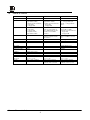
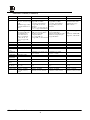
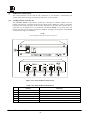
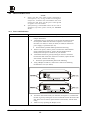
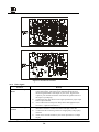
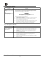
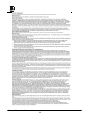
Kramer Electronics Ltd. USER MANUAL Format Interfaces Models: FC-10 FC-19 FC-4041C FC-4042 FC-4043 FC-4044 FC-4208 IMPORTANT: Before proceeding, please read paragraph entitled U U "Unpacking and Contents" KRAMER ELECTRONICS LTD. PN: 2900-004001 Rev 3 Table of Contents 1 1.1 1.2 INTRODUCTION A Word on Format Interfaces Factors Affecting Quality of Results 1 1 2 2 SPECIFICATIONS 3 3 HOW DO I GET STARTED? 5 4 UNPACKING AND CONTENTS 4.1 Optional Accessories 5 5 FORMAT INTERFACES 5.1 Getting to Know Your FC-10 5.2 Getting to Know Your FC-19 5.3 Getting to Know Your FC-4041C 5.4 Getting to Know Your FC-4042 5.5 Getting to Know Your FC-4043 5.6 Getting to Know Your FC-4044 5.7 Getting to Know Your FC-4208 6 7 8 9 10 11 12 6 INSTALLATION 6.1 Rack Mounting 13 13 7 CONNECTING TO VIDEO DEVICES 13 8 CONNECTING TO AUDIO DEVICES (FC-4208 ONLY) 13 9 USING THE MACHINES 9.1 Powering on the Machine 9.2 Composite/YC Video Selection (FC-19, FC-4043, FC-4044 only) 9.3 Adjusting the HUE (FC-4043, FC-4044 only) 9.4 Looping (FC-4041C only) 9.5 Audio Level Control (FC-4208 only) 13 13 13 13 13 14 10 TYPICAL APPLICATIONS 10.1 Interfacing Between Two Video Formats 10.2 Using PC Graphics in YC Production 10.3 Typical Composite/YC to Component/RGB Conversion 10.4 Integrating a Composite/RGB source Into a Composite/YC Switcher 10.5 Audio Format Conversion 14 14 15 15 16 17 11 18 5 6 TAKING CARE OF YOUR MACHINE 12 TROUBLESHOOTING 12.1 Power and Indicators 12.2 Video Signal Video Signal (continued) 12.3 Audio Signal (FC-4208 only) KRAMER ELECTRONICS LTD. 19 19 20 21 21 PN: 2900-004001 List Of Illustrations 1 2 3 4 5 6 7 8 9 10 11 12 13 FC-10 Front/Rear Panel Features FC-19 Front/Rear Panel Features FC-4041C Front/Rear Panel Features FC-4042 Front/Rear Panel Features FC-4043 Front/Rear Panel Features FC-4044 Front/Rear Panel Features FC-4208 Front/Rear Panel Features Interfacing Between Two Video Formats Using PC Graphics in YC Production Typical PC/Presentation Product Connections Integrating a Component/RGB source Into a Composite/YC Switcher Audio Format Conversion FC-10 Fuse Location 1 2 3 4 5 6 7 8 Factors Affecting Quality of Results FC-10 Front/Rear Panel Features FC-19 Front/Rear Panel Features FC-4041C Front/Rear Panel Features FC-4042 - Front/Rear Panel Features FC-4043 - Front/Rear Panel Features FC-4044- Front/Rear Panel Features FC-4208 - Front/Rear Panel Features 7 8 9 10 11 12 13 14 16 17 18 19 20 List Of Tables KRAMER ELECTRONICS LTD. 3 7 8 9 10 11 12 13 PN: 2900-004001 1 INTRODUCTION Congratulations on your purchase of this Kramer Electronics format interface. Since 1981, Kramer has been dedicated to the development and manufacture of high quality video/audio equipment. The Kramer line has become an integral part of many of the best production and presentation facilities around the world. In recent years, Kramer has redesigned and upgraded most of the line, making the best even better. Kramer’s line of professional video/audio electronics is one of the most versatile and complete available, and is a true leader in terms of quality, workmanship, price/performance ratio and innovation. In addition to the Kramer line of high quality format interfaces, such as the one you have just purchased, Kramer also offers a full line of high quality distribution amplifiers, switchers, processors, controllers and computerrelated products. This manual includes configuration, operation and option information for the following products from the Kramer line of format interfaces. All these interfaces are similar in operation and features. FC-10 - Composite-YC Transcoder FC-19 - RGB Decoder FC-4041C - Genlock Component Encoder 1.1 FC-4042 - RGB Component Transcoder FC-4043 - CV/YC Component Transcoder FC-4044 - Multistandard Decoder FC-4208 - Balanced Audio Transcoder A Word on Format Interfaces There are several video signal formats: Composite, Y/C, YUV (Y, R-Y, B-Y), RGB (S) analog and digital. Component analog video formats (YUV and RGB) are unmodulated signals, where the signal level represents the signal intensity, (e.g., 1 Volt of “Y” signal represents a maximum white level). Converting from YUV to RGB and vice versa does not involve modulation, and needs mainly an accurate matrix system. Composite video and Y/C (Super Video) contains chrominance (color) information, which is a modulated signal using the color subcarrier (3.58MHz in NTSC, 4.43MHz in PAL) as the carrier signal. Converting between Composite video and Y/C (and vice versa) involves adding or separating the color information from the luminance information. To convert from Composite and Y/C to Component video, a color encoder or color decoder is needed, with very complicated circuitry. The color encoder receives the component signal, and must create a chrominance signal by extracting the blue and red information from the component video signal and by modulating this information using the color subcarrier signal. The color decoder performs the opposite: it removes the color subcarrier and extracts the color difference signals to create the video “components”. The following format interfaces are described in this manual: Video Decoders - used to decode (convert) a composite video signal to Y/C and to decode a composite or Y/C signal to RGBS and/or Y, R-Y, B-Y. Video Encoders - used to create a chrominance signal from video components, e.g., to convert RGBS and/or Y, R-Y, and B-Y signals to composite video and Y/C. Video Transcoders - are bi-directional converters operating simultaneously in different directions, such as converting from RGBS to Y, R-Y, and B-Y in both directions in the same machine, going from composite to Y/C, bi-directionally or performing color decoding and encoding in the same machine at the same time. Audio Transcoders - used in audio and video production studios for converting from unbalanced low-level audio to balanced high-level audio, bi-directionally. Kramer Electronics Ltd. 1 1.2 Factors Affecting Quality of Results There are many factors affecting the quality of results when signals are transmitted from a source to an acceptor as described in Table 1: Table 1: Factors Affecting Quality of Results FACTOR Connection cables Sockets and connectors of the sources and acceptors Amplifying circuitry Distance between sources and acceptors Interference from neighboring electrical appliances EFFECT Low quality cables are susceptible to interference; they degrade signal quality due to poor matching and cause elevated noise levels. They should therefore be of the best quality. So often ignored, they should be of highest quality, since "Zero Ohm" connection resistance is the objective. Sockets and connectors also must match the required impedance (75Ω in video). Cheap, low quality connectors tend to rust, thus causing breaks in the signal path Must have quality performance when the desired end result is high linearity, low distortion and low noise operation Plays a major role in the final result. For long distances between sources and acceptors, special measures should be taken in order to avoid cable losses. These include using higher quality cables or adding line amplifiers. These can have an adverse effect on signal quality. Balanced audio lines are less prone to interference, but unbalanced audio should be installed far from any mains power cables, electric motors, transmitters, etc. even when the cables are shielded Kramer Electronics Ltd. 2 2 SPECIFICATIONS FC-10 Configuration Inputs Outputs FC-19 Transcoder 1 Composite Video, 1Vpp/75Ω on a BNC, 1 s-Video on a 4P connector, Y: 1Vpp/75Ω, C: 0.3Vpp/75Ω. 1 s-Video on a 4P connector, Y: 1Vpp/75Ω, C: 0.3Vpp/75Ω. 1 Composite Video, 1Vpp/75Ω on a BNC. Controls Video Bandwidth Nonlinearity Residual SC. DC Clamp Differential Gain Differential Phase K-Factor Luma S/N Ratio RGB Balance Error Dimensions (W, D, H) Weight Power Source 10MHz -1dB RGB Decoder 1 Composite Video, 1Vpp/75Ω on a BNC, 1 s-Video on a 4P connector, Y: 1Vpp/75Ω, C: 0.3Vpp/75Ω. RED, GREEN, BLUE, SYNC, 0.7Vpp/75Ωs, on BNCs, RGB (Analog), HS, VS TTL level on HD15 connector Rear input selector switch between Composite Video and s-Video Luma: 10MHz -3dB < 3% -38dB FC-4041C Encoder R (or R-Y), G (or Y), B (or BY) – 0.7Vpp/75Ω, Sync looping – 0.3Vpp/75Ω on BNCs 1 Composite Video, 1Vpp/75Ω on a BNC, 1 s-Video on a 4P connector, Y: 1Vpp/75Ω, C: 0.3Vpp/75Ω. Sync/Sync on Green, input selector - RGBS or Y, R-Y, B-Y. Exceeding 12MHz (Y) Less than 0.5dB -34dB 0 VDC Black Level. 0.24% 0.26Deg. 0.36% 0.3Deg. <0.05% (Y/C to CV). 79dB 64dB Less than 0.5dB 48 x 17.8 x 1U (cm) 19" x 7" x 1U. 2.5kg (5.5 lbs.) Approx. 230VAC, 50/60 Hz, (115VAC, U.S.A.) 12VA 16.5 x 12 x 4.5 (cm) 6.5" x 4.7" x 1.8" 0.6kg. (1.3lbs.) Approx. 12VDC, 110mA Kramer Electronics Ltd. 3 48 x 17.8 x 1U (cm) 19" x 7" x 1U 2.6kg. (5.8lbs.) Approx. 230VAC, 50/60 Hz, (115VAC, U.S.A.) 6 VA SPECIFICATIONS (Continued) FC-4042 Configuration Transcoder Inputs 1 component (Y, R-Y, B-Y), 1V, 0.7V, 0.7 Vpp /75Ω, 1 RGBS 0.7Vpp / 75Ω, for 100% saturation on BNCs Outputs 1 RGB 0.7Vpp / 75Ω, Sync 2Vpp/75Ωs, TTL level unloaded, for 100% saturation on BNCs, 1 component (Y, R-Y, B-Y), 1V, 0.7V, 0.7 Vpp /75Ω, BNCs Diff. Gain Diff. Phase K-Factor 0.4% Non Linearity Less than 0.2% DC Clamp Error Residual SC Y S/N Ratio Audio Bandwidth Audio THD Audio S/N Ratio Dimensions (W, D, H) Weight Power Source FC-4043 Transcoder Decoder: 1 Composite video, 1Vpp/75Ωs on a BNC, 1 s-Video: 1Vpp/75Ω (Y), 0.3Vpp/75Ω (C) on a 4P connector Encoder: 1 (Y, R-Y, B-Y) 1V, 0.7V, 0.7 Vpp /75Ω on BNCs Decoder: 1V, 0.7V, 0.7 Vpp /75Ω (Y, R-Y, B-Y), BNCs Encoder: 1Vpp/75Ω (Composite, BNC) Y/C: 1Vpp/75Ω (Y), 0.3Vpp/75Ω (C), 4P connector FC-4044 FC-4208 Decoder 1 Composite video, 1Vpp/75Ωs on a BNC, 1 s-Video: 1Vpp/75Ω (Y), 0.3Vpp/75Ω (C) on a 4P connector Audio Transcoder 4 balanced, +4dBm /50kΩ on female XLRs 4 unbalanced, 1Vpp / 50kΩ on RCAs. Component: 1V, 0.7V, 0.7Vpp /75Ω, BNCs RGB: 0.7Vpp/75Ω, for 100% saturation, Composite sync: 2Vpp/75Ω, BNCs 4 unbalanced, 1Vpp/50Ω, RCAs 4 balanced, +4dBm/50Ω, 18Vpp max., male XLRs 0.21% 0.19Deg. 1.2 % Less than 0.2% ±20 mV ±20 mV Composite to Y=30 mV, Y/C Composite to Y=30mV to Y = 15 mV Y/C to Y = 15mV Better than 71dB NA NA NA 20-30000Hz NA NA NA NA NA NA Less than 0.02% Better than 89dB 48 x 17.8 x 1U (cm) 19" x 7" x 1U 2.6kg. (5.8lbs.) Approx. 230VAC, 50/60Hz (115VAC, U.S.A.) 7.6VA 48 x 17.8 x 1U (cm) 19" x 7" x 1U 2.6kg. (5.8lbs.) Approx. 230VAC, 50/60Hz, (115VAC, U.S.A.) 19.5VA 48 x 17.8 x 1U (cm) 19" x 7" x 1U 2.6kg. (5.8lbs.) Approx. 230VAC, 50/60Hz, (115VAC, U.S.A.) 6.9VA 48 x 17.8 x 1U (cm) 19" x 7" x 1U 2.4kg. (5.3lbs.) Approx. 230VAC, 50/60Hz (115VAC, U.S.A.) 3.7VA Kramer Electronics Ltd. 4 3 HOW DO I GET STARTED? The fastest way to get started is to take your time and do everything right the first time. Taking 15 minutes to read the manual may save you a few hours later. You don’t even have to read the whole manual. If a section doesn’t apply to you, you don’t have to spend your time reading it. 4 UNPACKING AND CONTENTS The items contained in your Kramer Format interface package are listed below. Please save the original box and packaging materials for possible future transportation and shipment. Format Interface User Manual AC Power Cable (where applicable) 4 Rubber Feet DC Power Supply (where applicable) 4.1 Optional Accessories The following accessories, which are available from Kramer, can enhance implementation of your machine. For information regarding cables and additional accessories, contact your Kramer dealer. Rack Mechanical Adapter - Used to adapt smaller machines to a standard 1U rack. One or more machines may be installed on each adapter. 103AV - (Video Audio Distribution Amplifier) can be serially connected between the Format interface and the acceptor for video distribution. The 103AV splits a single video and audiostereo input source into three identical outputs. The 103AV uses an external 12VDC power source, and therefore is suitable for field work as well. The 103AV uses state of the art technology and microchip design, boasting a signal bandwidth of over 320MHz, thus making it suitable for the most demanding applications. SP-11 - (Video/Audio Processor) can be serially connected between the video/audio source and the format interface for video and audio control/correction. The machine provides camera control and luminance/white balance correction. It is also capable of performing composite to Y/C conversion and bi-directional transcoding. The machine allows full control over the video signal: video gain down to full fade, log or linear definition control, log or linear contrast control, color saturation control, black level control, red, green and blue controls and a screen splitter control for “before-after” comparison. The Input switch control is "audio-follow-video". VS-2042 - (4x2 Video Component Matrix) can be serially connected between the sources and the format interface for component video switching. The VS-2042 switches during the vertical interval for live studio operation. The VS-2042 has a built-in RS-232 interface for computer controlled operation, (software included) and several machines may be operated simultaneously via PC control. Its signal bandwidth exceeds 75MHz and it has DC coupled inputs and outputs for highest signal quality. Y, R-Y, B-Y or R, Gs, B signals are seamlessly routed. VIDEO TESTER - A new, unique, patented, indispensable tool for the video professional, the Video Tester is used to test a video path leading to/from an amplifier. By pressing only one touch switch it can trace missing signals, distinguish between good and jittery (VCR sourced) signals, and identify the presence of good signals. Whenever a video signal is missing, because of bad connections, cable breaks or faulty sources, the Video Tester is all you need. Kramer Electronics Ltd. 5 5 FORMAT INTERFACES This section describes all the controls and connections of your machine. Understanding the controls and connections helps you realize the full power of your machine. 5.1 Getting to Know Your FC-10 The KRAMER FC-10 Composite-YC Transcoder is designed to interface between the two popular video formats: Composite Video and YC (Super-Video). Hardly any VCR or camcorder transcodes from Composite Video to Super-Video, although it is necessary when material shot in Composite is to be edited into a Y/C production. The Kramer FC-10 is very small, and is fed from an external 12V DC supply, excellent for fieldwork. Front/Rear panel features of the FC-10 are described in Figure 1 and Table 2. NOTE For operation instructions refer to section 9. Figure 1: FC-10 Front/Rear Panel Features Table 2: FC-10 Front/Rear Panel Features No. 1. 2. 3. 4. 5. 6. Feature Power Switch CV IN BNC connector YC OUT 4P connector YC IN 4P connector CV OUT BNC connector 12VDC feed connector Function Illuminated switch supplies power to the unit. Composite video input. s-Video output. s-Video input. Composite video output. A DC connector that allows power to be supplied to the unit. Kramer Electronics Ltd. 6 5.2 Getting to Know Your FC-19 The KRAMER FC-19 is an industrial level RGB Decoder, which converts both Composite Video and Super-Video to their RGB components. Front/Rear panel features of the FC-19 are described in Figure 2 and Table 3. NOTE For operation instructions refer to section 9. Figure 2: FC-19 Front/Rear Panel Features Table 3: FC-19 Front/Rear Panel Features No. Feature Function Illuminated switch supplies power to the unit. 1. Power Switch 2. Internal trimmer (bottom accessible) Not used. WARNING! Adjustments or attempted adjustments of the trimmer are not allowed. Failure to comply with this warning may damage the machine. 3. 4. 5. 6. 7. 8. 9. 10. Composite BNC connector YC 4P connector Select CV/YC switch SYNC BNC connector RED BNC connector GREEN BNC connector BLUE BNC connector VGA/Multi HD15 connector 11. Power Connector Composite video input. s-Video input. Selects either Composite or s-Video to be converted. Sync signal output. RED signal output. GREEN signal output. BLUE signal output. VGA type signal output (horizontal sync frequency = 15kHz, no scan conversion.) A 3-prong AC connector allows power to be supplied to the unit. Directly underneath this connector, a fuse holder houses the appropriate fuse. Kramer Electronics Ltd. 7 5.3 Getting to Know Your FC-4041C The KRAMER FC-4041C is a full broadcast, state-of-the-art Genlock RGB/Component to Composite Video/YC Encoder designed for studio and other demanding applications. The FC4041C encodes RGBS or Component Y, R-Y and B-Y signals to Composite Video and SuperVideo signals. All inputs are looped through with termination switches, allowing for parallel connection to other RGBS/Component acceptors. From front panel switches, the FC-4041C allows the user to select whether Sync is separate or riding on Green. The user can also select whether to convert RGBS or Component signals to Composite and Y/C. The outputs are DC coupled and Black-Level clamped. Front/Rear panel features of the FC-4041C are described in Figure 3 and Table 4. NOTE For operation instructions refer to section 9. Figure 3: FC-4041C Front/Rear Panel Features Table 4: FC-4041C Front/Rear Panel Features No. 1. 2. Feature Power Switch Trimmers Function Illuminated switch supplies power to the unit. Not used. WARNING! Adjustments or attempted adjustments of the trimmers are not allowed. Failure to comply with this warning may damage the machine. 3. 4. INPUT RGB/Comp pushbutton SYNC Black/G+S pushbutton 5. 6. Red/R-Y IN BNC connector Red/Green/Blue 75Ω/Hi-Z selectors Red/Green/Blue LOOP BNC connector Green/Y IN Blue/B-Y IN BNC connector Sync IN BNC connector Y/C 4P connector COMPOSITE BNC connector Power Connector 7. 8. 9. 10. 11. 12. 13. Illuminated pushbutton: selecting RGB or Component input Illuminated pushbutton: selecting sync source – separate or riding on Green. Red/R-Y Input Selects “75Ω“ or “HI-z” impedance when pushed in the selected direction (for looping select "Hi-z"). Provides Red/R-Y looping capability to increase number of outputs. Green/Y Input Blue/B-Y Input Sync signal input. s-Video output. Composite video output. A 3-prong AC connector allows power to be supplied to the unit. Directly underneath this connector, a fuse holder houses the appropriate fuse. Kramer Electronics Ltd. 8 5.4 Getting to Know Your FC-4042 The KRAMER FC-4042 RGB-Component Transcoder interfaces between the two most widely used professional video formats: Component Video (Y, R-Y, B-Y) and RGBS. In many video studios and production centers there is a need to convert from one format to the other, and the Kramer FC-4042 is the perfect choice as it operates simultaneously in both directions. Front/Rear panel features of the FC-4042 are described in Figure 4 and Table 5. NOTE For operation instructions refer to section 9. Figure 4: FC-4042 Front/Rear Panel Features Table 5: FC-4042 - Front/Rear Panel Features No. Feature Function 1. Power Switch 2. G+S/G IN pushbutton 3. G/G+S OUT pushbutton 4. 5. 6. 7. 8. 9. 10. Illuminated switch supplies power to the unit. Selects sync or sync on green on the RGB signals for the "IN" channel. Selects sync or sync on green on the RGB signals for the " OUT " channel. IN Y, R-Y, B-Y BNC connectors Component video inputs. RGB outputs. OUT RED, GREEN, BLUE BNC connectors OUT SYNC BNC connector Sync signal output. IN RED, GREEN, BLUE BNC RGB inputs. connectors IN SYNC BNC connector Sync signal input. OUT Y, R-Y, B-Y BNC Component video outputs. connectors Power Connector A 3-prong AC connector allows power to be supplied to the unit. Directly underneath this connector, a fuse holder houses the appropriate fuse. Kramer Electronics Ltd. 9 5.5 Getting to Know Your FC-4043 The KRAMER FC-4043 CV/YC - Component Transcoder interfaces between Composite video and Y/C to the most widely used professional video format - Component Video (Y, R-Y, B-Y) bi-directionally. In many video studios and production centers there is a need to convert from one format to the other, and the Kramer FC-4043 is the perfect choice as it operates in the most common standards - PAL, SECAM and NTSC (both) – and bi-directionally. Decoding operation is microprocessor controlled via the internal I2C bus and the machine allows standards conversion between PAL and SECAM. Front/Rear panel features of the FC-4042 are described in Figure 5 and Table 6. NOTE For operation instructions refer to section 9. Figure 5: FC-4043 Front/Rear Panel Features Table 6: FC-4043 - Front/Rear Panel Features No. Feature 1. 2. Power Switch ENC/TRANS pushbutton 3. PAL, SECAM, 3.58, 4.43 encoder pushbuttons 4. Internal trimmers 5. CV/YC pushbutton 6. 7. HUE (+/-) pushbuttons PAL, SECAM, 3.58, 4.43 LEDS 8. INPUTS CV BNC connector 9. INPUTS Y/C 4P connector 10. OUTPUTS Y, R-Y, B-Y BNC connectors 11. INPUTS Y, R-Y, B-Y BNC connectors 12. OUTPUTS YC 4P connector 13. OUTPUTS CV BNC connector 14. Power Connector Function Illuminated switch supplies power to the unit. Encoder or Transcoder function selector. When Transcoder is selected (switch is not illuminated), an internal link is formed between the components outputs of the Decoder section and the component inputs of the Encoder section – allowing for example - Composite SECAM to PAL conversion (or vice versa) Illuminated pushbuttons: selecting the output encoding standard desired. Note that the machine does not scan convert between PAL and NTSC but can allow for NTSC 4.43 output from an NTSC 3.58 input for example. Not used. WARNING! Adjustments or attempted adjustments of the trimmers are not allowed. Failure to comply with this warning may damage the machine. Illuminated pushbutton. Selects either composite video or Y/C signal at the decoder input when pressed. Only active when NTSC is used, for changing output picture hue. Illuminates the appropriate LED when one of the corresponding standards input signal is auto detected (blinks when there is no input.) Composite video input to the Decoder. Y/C input to the Decoder. Component video outputs from the Decoder. Component video inputs to the Encoder. YC output from the Encoder. Composite video output from the Encoder. A 3-prong AC connector allows power to be supplied to the unit. Directly underneath this connector, a fuse holder houses the appropriate fuse. Kramer Electronics Ltd. 10 5.6 Getting to Know Your FC-4044 The KRAMER FC-4044 Multistandard Decoder interfaces from Composite video and Y/C to the most widely used professional video formats - Component Video (Y, R-Y, B-Y) and RGBS. In many video studios and production centers there is a need to convert from one format to the other and the KRAMER FC-4044 is the perfect choice as it operates in the most common standards PAL, SECAM and NTSC (both). Decoding is microprocessor controlled via the internal I2C bus. Front/Rear panel features of the FC-4044 are described in Figure 6 and Table 7. NOTE For operation instructions refer to section 9. Figure 6: FC-4044 Front/Rear Panel Features Table 7: FC-4044- Front/Rear Panel Features No. 1. 2. 3. 4. Feature Power Switch G/G+S pushbutton CV/YC pushbutton PAL, SECAM, 3.58, 4.43 pushbuttons 5. 6. 7. 8. HUE (+/-) pushbuttons INPUTS CV BNC connector INPUTS YC 4P connector OUTPUTS Y, R-Y, B-Y BNC connector 9. OUTPUTS RED, G/G+S, BLUE connectors 10. OUTPUTS SYNC connector 11. Power Connector Function Illuminated switch supplies power to the unit. Selects sync or sync on green on the G/G+S BNC connector. Selects either composite video or YC input signal for conversion. Illuminated pushbuttons detect the existence of the following standards PAL, SECAM, NTSC 3.58 or 4.43. Pressing the buttons can force the decoder to accept the wrong standard and is therefore not recommended. Active when NTSC is used. Composite video input. YC input. Component video outputs. RGB outputs (G or G+S are selected via the G/G+S pushbutton). Composite sync output. A 3-prong AC connector allows power to be supplied to the unit. Directly underneath this connector, a fuse holder houses the appropriate fuse. Kramer Electronics Ltd. 11 5.7 Getting to Know Your FC-4208 The KRAMER FC-4208 Balanced/Unbalanced Audio Transcoder is a bi-directional, versatile tool, converting between the two most commonly used audio standards. The machine allows gain or attenuation while transcoding, to compensate for the 14dB change between IHF audio levels and the newly adopted, balanced DAT input levels. Very low noise and distortion components are used throughout the machine. The FC-4208 has 4 balanced audio inputs on XLRs and 4 unbalanced audio outputs on the balanced to unbalanced channels, and 4 unbalanced inputs and 4 balanced audio outputs on XLRs on the unbalanced to balanced channels. Each set (8 all together) has an individual level control for perfect matching. Front/Rear panel features of the FC-4208 are described in Figure 7 and Table 8. NOTE For operation instructions refer to section 9. Figure 7: FC-4208 Front/Rear Panel Features Table 8: FC-4208 - Front/Rear Panel Features No. 1. 2. 3. 4. 5. 6. 7. 8. Feature Power switch Unbalanced to Balanced Level Controls Balanced to Unbalanced Level Controls IN Channel 1-4 XLR female connectors OUT Ch RCA connectors IN Ch RCA connectors OUT Channel 5-8 XLR male connectors Power Connector Function Illuminated switch supplies power to the unit. Control the balanced audio level outputs. Control the unbalanced audio level outputs. Balanced audio inputs. Unbalanced audio outputs. Unbalanced audio inputs. Balanced audio outputs. A 3-prong AC connector allows power to be supplied to the unit. Directly underneath this connector, a fuse holder houses the appropriate fuse. Kramer Electronics Ltd. 12 6 6.1 INSTALLATION Rack Mounting The FC-19, FC-4041C, FC-4042, FC-4043, FC-4044 and FC-4208 may be rackmounted in a standard 19” (1U) EIA rack, and include rack “ears” at the ends of the front panel. To mount them, simply place the unit's ears against the rack rails of your rack, and insert standard screws through each of the four corner holes. The FC-10 can be rack mounted using a special adapter (see section 4.1). These devices do not require any specific spacing for ventilation above or below the unit. 7 CONNECTING TO VIDEO DEVICES Video sources and output devices (such as monitors, projectors or recorders) may be connected to the machines through the BNC and/or 4P type connectors located on the back of the units. Unused inputs are terminated to 75Ω, and active inputs should be terminated by the connecting source. All signal connections that use more than one cable interconnecting between devices should be of equal length. (Example: RGB cables between a camera and the machine should be equal in length.) The signals supported by the various models are: Composite Video, s-Video (Y/C), Component Video and Analog Red, Green, Blue and Sync signals (RGBS). 8 CONNECTING TO AUDIO DEVICES (FC-4208 ONLY) Audio sources and output devices (such as amplifiers or recorders) may be connected to the machine through the RCA or/and XLR type connectors located on the back of the machine. 9 USING THE MACHINES 9.1 Powering on the Machine NOTES 1) 2) 1. 2. The machine should only be powered on after all connections are completed and all source devices have been powered on. Do not attempt to connect or disconnect any video, audio or control signals to the machine while it is powered on! The socket-outlet should be near the equipment and should be easily accessible. To fully disconnect equipment, remove power cord from socket. Toggle the switch on the far-left front panel to the up position. The switch will glow. Operate sources and the acceptors. 9.2 Composite/YC Video Selection (FC-19, FC-4043, FC-4044 only) Selecting either Composite or Super video to be converted is simply done by using the Select CV/YC switch (FC-19) or the CV/YC pushbutton (FC-4043, FC-4044). 9.3 Adjusting the HUE (FC-4043, FC-4044 only) The term "HUE" is often used synonymously with the term "tint". It is the dominant wavelength, which distinguishes a color or tint as red or yellow, etc. Video hue is influenced by several factors: Adjustment of the white balance of the camera, quality of the electronic equipment which is being used, and lighting of the scene. In the American NTSC standard, hue errors are more common than in the European PAL standard due to a different color encoding system. The PAL system compensates for color problems and corrects wrong hues during operation. Video color processors are needed to adjust and correct hue problems. To adjust the HUE, simply press the HUE "+" or "-" pushbuttons, until a satisfactory picture color is achieved. 9.4 Looping (FC-4041C only) The looping function enables the operator to connect several machines to the format interface. The operator must always switch the termination switch of the first and middle machines to "Hiz". The last machine’s termination switch should always be at "75Ω" to maintain well-matched lines (of 75Ω impedance) from the first to the last machine. Note that if the looping function is not used, the termination switch should be set to "75Ω". Kramer Electronics Ltd. 13 9.5 Audio Level Control (FC-4208 only) A balanced audio signal is made of two antiphase signals, traveling on two wires (sometimes with a third - a ground reference / shield wire). A balanced signal achieves better signal-to-noise ratio, and is more immune to noise and interference. On the receiving end there is a differential amplifier, which amplifies only the difference between the antiphase signals, thus canceling noise which is picked up along the way and which is common mode. The balanced system is usually used either when very low signals are to be transmitted over long distances (such as those generated from high quality microphones) or at broadcast audio studios, for highest quality signal recreation. To control the balanced/unbalanced signal, gently adjust the Level control knobs until a satisfactory audio level is achieved. 10 TYPICAL APPLICATIONS 10.1 Interfacing Between Two Video Formats The FC-10 can be used for simultaneous bi-directional conversion from composite video to YC and from YC to composite for studio applications as shown in Figure 8. In such a setup, YC signals can be monitored on a composite video monitor! Perform the following steps (as necessary): 1. Connect a composite video source to the CV IN connector of the FC-10. 2. Connect an YC acceptor to the YC OUT connector of the FC-10. 3. Connect an YC video source to the YC IN connector of the FC-10. 4. Connect a composite video acceptor to the YC OUT connector of the FC-10. 5. Connect the FC-10 to an appropriate 12VDC power supply, with proper polarity. 6. Operate sources, acceptors and the FC-10. Press one of the control switches to select PAL or NTSC mode of operation. NOTE The machine cannot convert composite PAL to Y/C in NTSC. Encoding and decoding is performed only within the same standard. Figure 8: Interfacing Between Two Video Formats Kramer Electronics Ltd. 14 10.2 Using PC Graphics in YC Production Some scan converters, which convert VGA/XGA graphics to video, generate only a composite video signal. The FC-10 converts composite video signal to s-Video (YC), thus enabling usage of computer generated graphics in professional YC productions, as shown in Figure 9. Perform the following steps (as necessary): 1. Connect a composite video source to the CV IN BNC connector of the FC-10 2. Connect an YC acceptor to the YC OUT 4P connector of the FC-10. 3. Operate source, acceptor and the FC-10. Figure 9: Using PC Graphics in YC Production 10.3 Typical Composite/YC to Component/RGB Conversion 30B Figure 10 illustrates a typical set up of the Kramer format converters described in this manual: incoming input signals from composite and YC (s-Video) sources are converted by a Multistandard Decoder (FC-4044, in this case) to component and RGB output signals, that are then sent to two different acceptors. A Chroma Keyer/Mixer may be connected in parallel to the RGB outputs in order to control the RGB display. A mixer is a device used to combine video signals from two or more sources. Synchronized inputs are mixed with each other and various special effects patterns and shapes are added in accordance with the proficiency of the video mixer being used. Perform the following steps (as necessary): 1. Connect CV/YC sources to the inputs (FC-4044 in this case). 2. Connect the outputs to two different RGB/component acceptors. 3. Operate sources, acceptors and your machine. 4. Use the front panel control functions if necessary (see section 9 for more details). Kramer Electronics Ltd. 15 Figure 10: Typical PC/Presentation Product Connections 10.4 Integrating a Composite/RGB source Into a Composite/YC Switcher 31B It is sometimes necessary for pre-edit purposes, to switch a component video source alongside composite or Y/C sources. Some but not all of the component video sources include a composite or a Y/C output. In order to perform the above-mentioned task, a video encoder is needed in order to convert either YUV or RGB signals to composite and Y/C signals, as shown in Figure 11. Kramer Electronics Ltd. 16 Figure 11: Integrating a Component/RGB Source Into a Composite/YC Switcher 10.5 Audio Format Conversion 32B Professional audio usually requires balanced audio signals that are less prone to interference due to the differential signal setup. When using unbalanced and balanced signals at the same setup, amplification or attenuation is needed to match the levels. An Audio Transcoder (FC-4208 in this case) can be used for this purpose and for signal conversion as well, as shown in Figure 12. Perform the following steps (as necessary): 1. Connect one or more balanced audio sources to Channel 1 and Channel 2 XLR inputs of the FC-4208. 2. Connect one or more unbalanced audio sources to Channel 1 and Channel 2 RCA inputs of the FC-4208. 3. For unbalanced audio distribution, connect the outputs of the machine to an audio distributor (Kramer VM-50A for example.) 4. For balanced audio distribution, connect the outputs of the machine to a balanced audio distributor (Kramer VM-1110 for example.) 5. Operate sources, acceptors and your machine. 6. Use the front panel control functions if necessary (see section 9 for more details). Kramer Electronics Ltd. 17 Figure 12: Audio Format Conversion 11 TAKING CARE OF YOUR MACHINE 10B Do not locate your machine in an environment where it is susceptible to dust or moisture. Both of these may damage the electronics, and cause erratic operation or failure. Do not locate your machine where temperature and humidity may be excessive. Doing so may also damage the electronics, and cause erratic operation or failure of your machine. Do not clean your machine with abrasives or strong cleaners. Doing so may remove or damage the finish, or may allow moisture to build up. Take care not to allow dust or particles to build up inside unused or open connectors. Kramer Electronics Ltd. 18 12 TROUBLESHOOTING NOTES 1. 2. Please note that if the output signal is disturbed or interrupted by very strong external electromagnetic interference, it should return and stabilize when such interference ends. If not, turn the power switch off and on again to reset the machine. If the following recommended actions do not result in satisfactory operation, please consult your KRAMER Dealer. 12.1 Power and Indicators Problem No Power Remedy 1. 2. Confirm that the rocker switch is in the “ON” position, and that the lamp is illuminated. Confirm that power connections are secured at the machine and at the receptacle. Make sure the mains receptacle is active (FC-19, FC4041C, FC-4042, FC-4043, FC-4044, FC-4208) or that the DC power supply is operational (FC-10). For the Mains operated models perform the following: If there is no power, remove power cord from AC outlet and then using a flat head screwdriver, remove the fuse holder located directly below the power connector on your machine. 2. Confirm that the fuse is good by looking for the wire connected between the ends of the fuse. If the wire is broken, replace the fuse with another, with the same rating. 1. 1. 2. 3. For the DC operated models perform the following: Using a Philips screwdriver, remove the 4 side screws attaching the machine's cover (see below). Locate the fuse holder inside your machine (see Figure 13). Confirm that the fuse is good by looking for the wire connected between the ends of the fuse. If this wire is broken, replace the fuse with another, with the same rating. Install cover by replacing the Philips screws. Kramer Electronics Ltd. 19 Figure 13: FC-10 Fuse Location 12.2 Video Signal Problem No video at the output device Remedy 1. 2. 3. Video level is too high or too dim. 1. 2. 3. Confirm that your source and output devices are powered on and connected properly. The input of your machine should be of an identical signal format at the output of your source. Signals at the output of your machine should be of an identical signal format as at the input of your display. Confirm that any other device in the signal path has the proper input and/or output selected. Use a Video Tester to help trace faulty cables and equipment (see section 4.1 "Optional Accessories") Verify that the lines are well matched through 75Ω impedances; otherwise it results in a video level that is too high or too dim. Confirm that the connecting cables are of high quality and properly inserted. Check level controls located on your source input device or output display. Kramer Electronics Ltd. 20 Video Signal (continued) Problem Noise bars are "rolling" up or down in the output image or: Remedy Hum bars (ground loop) are caused by a difference in the ground potential of any two or more devices connected to your signal path. This difference is compensated by passing that voltage difference through any available interconnection, including your video cables. WARNING! Do not disconnect the ground from any piece of video equipment in your signal path! Low Frequency Hum in the output signal Check the following to remove hum bars: 1. Confirm that all interconnected equipment is connected to the same phase of power, if possible. 2. Remove equipment connected to that phase that may introduce noise, such as motors, generators, etc. 3. Disconnect all interconnect cables and reconnect them one at a time until ground loop reappears. Disconnect the affected cable and replace, or insert an isolation transformer in the signal path. 12.3 Audio Signal (FC-4208 only) Problem No audio at the output device, regardless of input selected Remedy 1. 2. Audio level is too low 1. 2. Confirm that your source and output devices are powered and properly connected. Audio signals connected to the output of your machine should be properly wired to the input of your machine or recorder. Confirm that any other devices in the signal path has the proper input and/or output selected. Confirm that the connecting cables are of high quality and properly built. Take special care in noting the wiring configuration of balanced to unbalanced cables. Check level controls located on your source input device or output display or recorder. Kramer Electronics Ltd. 21 Kramer Electronics Ltd. 22 For the latest information on our products and a list of Kramer distributors, visit our Web site: www.kramerelectronics.com where updates to this user manual may be found. We welcome your questions, comments and feedback. ! SAFETY WARNING Disconnect the unit from the power supply before opening and servicing P/N: 2900- 004001 Rev: 3