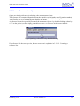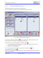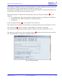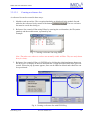
1
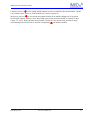
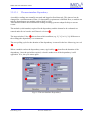
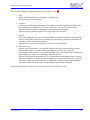
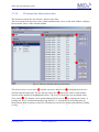
IMKO Micromodultechnik GmbH
ENVISLog
Version 3.0
User manual
Status September 2004
ENVISLog V3.0
Ref. No. El0901-04-e
1
IMKO Micromodultechnik GmbH
Thank you for choosing an IMKO measurement system.
Please read these instructions carefully to ensure optimum measurements. If any points
remain unclear after doing so, please contact your registered dealer or IMKO direct. We
will be glad to help you.
IMKO Micromodultechnik GmbH
Im Stöck 2
D-76275 Ettlingen
Germany
Telephone:
+49-(0)7243-5921-0
Fax:
+49-(0)7243-90856
E-mail:
[email protected]
Internet:
http://www.imko.de
Status 05.06.2007
ENVISLog 3.0 is a modern parameterising and measurement data
recording software and was developed for IMKO Micromodultechnik
GmbH by ibd.
Ibd site:
http://www.ibd-demmerle.de/
Questions, ideas or criticism?
Contact us at:
[email protected]
Text and diagrams in this manual were complied with the greatest care and
attention. Nevertheless, errors cannot be entirely ruled out. The publisher
accepts no liability whatsoever for incorrect information or the consequences
of its use.
All information subject to alteration without prior notice.
Ibd (Enkenbach, den 15.09.2004)
ENVISLog V3.0
Ref. No. El0901-04-e
2
IMKO Micromodultechnik GmbH
1
List of contents
1
List of contents ..................................................................................................... 3
1.1
2
Quick-installation guide..................................................................................... 4
Using ENVISLog ................................................................................................. 5
2.1
Registration ..................................................................................................... 7
2.2 Version change (ENVISLog 2.x to 3.x) .......................................................... 8
2.3 Automatic restart after power failure............................................................... 8
3
Program operation ................................................................................................ 9
3.1
The main window ........................................................................................... 9
3.2
The menu bar ................................................................................................ 10
3.2.1
The menu Measurement circuit ........................................................... 10
3.2.1.1 The menu item Open .......................................................................... 11
3.2.1.2 The menu item Bus configuration...................................................... 12
3.2.1.2.1 Creating a reference list................................................................ 14
3.2.1.3 The menu item Module configuration ............................................... 16
3.2.1.3.1 The user interface Dependency .................................................... 18
3.2.1.4 The menu item Measurement data..................................................... 20
3.2.1.4.1 The user interface Manual............................................................ 21
3.2.1.5 The menu item Export........................................................................ 22
3.2.2
The menu Options ................................................................................ 22
3.2.2.1 The option Language ......................................................................... 23
3.2.2.2 The option Places after the decimal point ......................................... 23
3.2.3
The menu View..................................................................................... 24
3.2.4
The menu Info ...................................................................................... 25
3.3
The status bar ................................................................................................ 25
A1
Supported modules ....................................................................................... 26
ENVISLog V3.0
Ref. No. El0901-04-e
3
IMKO Micromodultechnik GmbH
1.1
Quick-installation guide
1.)
Extract ENVISlog to a directory
2.)
Start EnvisLog.exe
3.)
Under "Measurement circuit", click on "Bus configuration"
4.)
Enter the lowest serial number (e.g.#12672) under "Search for serial numbers" - "from"
5.)
Enter the highest serial number (e.g.#12682) under "Search for serial numbers" - "to"
6.)
Click on the Start button under "Search for serial numbers"
6a.)
ENVISlog now searches for modules
7.)
After the search (all modules must be found), click on "Ascending" under "ID allocation"
7a.)
ENVISlog now distributes station numbers to the serial numbers
8.)
Under "Recognised modules", now click on "Add to reference"
9.)
Under "Reference list", click on "Save"
10.)
Enter the measurement circuit name + .txt (e.g.: Test.txt) and click on "Save"
10a.) The measurement circuit is saved
11.)
Under "Measurement circuit", click on "Module configuration"
11a.) ENVISlog now requires a few seconds to initialise the measurement circuit
12.)
Specify start time & date in the window "Start of measurement"
13.)
Click on "Apply to all modules"
14.)
Specify measuring rate in the window "Measurement period"
15.)
Click on "Apply to all modules"
16.)
Under "Measurement circuit", click on "Measurement data"
17.)
Click on Start
18.)
Confirm "Save configuration"
19.)
Congratulations, configuration is complete and the measurement circuit is operational.
For measurement data, see "Measurement data"
20.)
If you stop the measurement circuit and quit the "Measurement data" window, the data
is lost until ENVISlog has been registered.
If you have any questions, please do not hesitate to call us.
ENVISLog V3.0
Ref. No. El0901-04-e
4
IMKO Micromodultechnik GmbH
2
Using ENVISLog
ENVISLog is a modern software for parameterising and recording measurement data from IMPBUS modules made by IMKO Micromodultechnik GmbH. The operating systems required are
Microsoft-Windows98 / -2000 / -NT / or –XP Professional.
For communication via a network, IMP modules are parameterised directly on site and the
measurement data saved. Several ENVISLog applications can be installed at a variety of operating
locations. Communication between the measuring location and operating location is performed via
an MS network. The measurement data can be summoned through the MS network.
PC
ENVISLog
Server Version
Bus module
RS232
IMP-Bus central
station
Bus module
IMP-BUS
Bus module
Bus module
Bus module
MS network
PC
ENVISLog
Client Version
PC
ENVISLog
Client Version
PC
ENVISLog
Client Version
Communication via network connection
ENVISLog V3.0
Ref. No. El0901-04-e
5
IMKO Micromodultechnik GmbH
Communication between the measuring location and operating location can also be carried out via
FTP. The measurement data can be summoned via the Internet in this way.
PC
ENVISLog
Server version
Bus module
RS232
IMP-Bus
central station
Bus module
IMP-BUS
Bus module
Bus module
Bus module
FTP server
Internet
LAN
WAN
FTP Client
FTP Client
FTP Client
FTP Client
PC
ENVISLog
Client-Version
PC
ENVISLog
Client-Version
PC
ENVISLog
Client-Version
PC
ENVISLog
Client-Version
Remote connection via FTP
ENVISLog V3.0
Ref. No. El0901-04-e
6
IMKO Micromodultechnik GmbH
2.1
Registration
ENVISLog must be registered for it to be used to its full extent.
Until ENVISLog is registered, a dialogue appears every 5 minutes requesting registration.
Measurement circuit recording is interrupted every time the dialogue appears.
This dialogue contains two boxes labelled "Serial number" and "Code". The serial number is
formed by the product ("envis") and the number of the PC number the software is installed on.
Once you have given us of the serial number, you recieve a code (e.g. "01jpdjfo9tzbiowk"). You
then enter this code in the appropriate box. By clicking once on the button "Confirm code", your
version of the software can be used without restriction.
ENVISLog V3.0
Ref. No. El0901-04-e
7
IMKO Micromodultechnik GmbH
2.2
Version change (ENVISLog 2.x to 3.x)
Measurement dat recorded with older ENVISLog versions (below 3.x) have to be converted with a
special software program.
This program can be downloaded from our website.
2.3
Automatic restart after power failure
The following criteria must be met to ensure that ENVISLog restarts automatically if the power
supply to the computer is cut.
1. Create a link for the executable file (ENVISLog 3.0.exe) to the autostart folder in
Windows.
2. Attach the parameter MEASUREMENT:<Measurement circuit> /BAUD RATE:<Baud
rate> /COMPORT:<Comport> /AUTOSTART under Properties of ENVISLog 3.0.exe ->
Link -> Destination.
e.g. “E:\Programmes\ENVISLOG 3.0.exe /MEASUREMENT:<Measurement circuit1>
/BAUD RATE:<9600> /COMPORT:<Com1> /AUTOSTART“
ENVISLog V3.0
Ref. No. El0901-04-e
8
IMKO Micromodultechnik GmbH
3
Program operation
This section explains step by step how to use the software.
3.1
The main window
The following image appears after starting the program. All the functions for recording
measurement data can be carried out from here.
c
e
h
f
g
i
d
Fig. 1: The main window
The main window comprises a Menu bar c and Status bar d, the display Measurement circuit
name e, the viewing windows Module listf and Measurement datag with the groups time
period h and Measurement i. The structure is designed to allow very simple, clear and easyto-learn operation. The program interface shown above is explained systematically in the sections
to follow.
ENVISLog V3.0
Ref. No. El0901-04-e
9
IMKO Micromodultechnik GmbH
3.2
The menu bar
The menu bar shown in the main window contains the menus: Measurement circuit, Options,
Layout and Info.
Fig. 2: The menu bar
3.2.1
The menu Measurement circuit
Fig. 3: The menu Measurement circuit
Menu function
Open
Bus configuration
Module configuration
Measurement data
Export
Quit
ENVISLog V3.0
Description
Opens an existing reference list relating to the measurement
circuit.
See Section 3.2.1.1
Shows the user interface Bus configuration.
See Section 3.2.1.2
Shows the user interface Module configuration.
See Section 3.2.1.3
Shows the user interface Measurement data (Main window).
See Section 3.2.1.4
Transforms a reference list into an Excel-readable format.
See Section 3.2.1.5
End measurement and quit program.
Ref. No. El0901-04-e
10
IMKO Micromodultechnik GmbH
3.2.1.1
The menu item Open
Opens an existing reference list relating to the measurement circuit.
The reference list contains information about the module's serial number and ID (station number)
as well as the name and type of the module. It can be opened and edited using Editor.
The reference list is for comparing the modules on the bus.
A reference list can be opened by means of the menu item Open or by double-clicking (shown by
a "2" on the pointer) on the display panel Measurement circuit name in the main window.
Fig. 4: Opening a reference list by double-clicking
If a reference list does not yet exist, how to create one is explained in 3.2.1.2.1 Creating a
reference list.
ENVISLog V3.0
Ref. No. El0901-04-e
11
IMKO Micromodultechnik GmbH
3.2.1.2
The menu item Bus configuration
The menu item opens the user interface Bus configuration.
The user interface Bus configuration is for setting up the measurement circuit.
c
d
e
g
f
h
i
j
Fig. 5: The user interface Bus configuration
The connected COM-Port and baud rate c can be set. The button "Change baud rate" must be
pressed in order to set the baud rate changed in the Combo-Box.
The modules can be sought according to three different criteria d .
1. by loaded reference list, i.e. the modules are sought that are shown in the reference list.
2. by one or more IDs (station numbers).
3. by one or more serial numbers.
The viewing windows show the modules recognised by scanning the bus e and
those in the loaded reference list f .
The number of recognised modules and the number of modules from the reference list are shown
via the viewing windows.
ENVISLog V3.0
Ref. No. El0901-04-e
12
IMKO Micromodultechnik GmbH
If the number of modules found is less than the number of modules from the reference list, not all
the modules have been extracted that are entered in the reference list.
If the number of modules in the reference list is less than the number of recognised modules, new
modules have been added to the measurement circuit.
When new modules are added to the measurement circuit, the ID (station number) g can be
assigned
1. in ascending order (ID (station number) assignment in order of ascending serial number)
2. manually (also by double-clicking in the viewing windows)
3. by reference.
Newly recognised modules h can be added to the reference list.
The contents of the left-hand viewing window (recognised modules) can be deleted here as well.
The reference list i can be reloaded or, when adding a new module, saved again.
The contents of the right-hand viewing window (reference list) can be deleted here as well.
The whole log is shown in the lower left-hand window j which can also be saved as a text file.
The viewing window is enlarged by clicking on the log.
Fig. 6: The Log window
ENVISLog V3.0
Ref. No. El0901-04-e
13
IMKO Micromodultechnik GmbH
3.2.1.2.1
Creating a reference list
A reference list can be created in three ways:
1. Modules read out on-line. The recognised modules are displayed in the module list and
added to the reference list by means of the button
. The new reference
list must be saved after doing so.
2. Reference list created off-line using Editor by entering the serial number, the ID (station
number) and the module name, separated by tab.
Example:
Fig. 7: Creating a reference list using Editor
Note: The tab arrows shown in red are not normally visible in Editor. They are only shown
here for clarity.
3. Reference list created off-line via ENVISLog by clicking the right-hand mouse button on
the Reference list display in the user interface Bus configuration described in the previous
section. When the pop-up menu appears, lines can be added or deleted and edited line can
be repositioned.
Fig. 8: Creating a reference list with ENVISLog
ENVISLog V3.0
Ref. No. El0901-04-e
14
IMKO Micromodultechnik GmbH
The input window opens using Edit line or by double-clicking on the required line.
Fig. 9: Input window
After entering the serial number, bus ID (station number) and the module type, the module
is added to the reference list by clicking on Ok.
ENVISLog V3.0
Ref. No. El0901-04-e
15
IMKO Micromodultechnik GmbH
3.2.1.3
The menu item Module configuration
This menu item opens the user interface Module configuration.
The user interface Module configuration is for setting up the modules.
c
e
d
f
g
h
i
Fig. 10: The user interface Module configuration
The selected Measurement circuit c and the respective Module list d are displayed on the user
interface. Depending on the module selected, additional information is also given about the hard
and software version e.
The start of the measuring interval is set as a date and time under Start of measurement f .
Pressing the
-key to the right of the current date reveals a calendar to facilitate entering the
date.
The start time can be moved up or down by one unit using the
-key after marking the hours,
minutes or seconds.
Both input modifications can be carried out by direct entry.
The start of measurement can be set separately by date and time for every module or identically
for all of them.
ENVISLog V3.0
Ref. No. El0901-04-e
16
IMKO Micromodultechnik GmbH
Channel selection g is for setting which channel is to be recorded for the measurement. (In the
case of data export, however, both channels are always exported.)
Measuring interval h is for setting the temporal intervals at which readings are to be taken.
In the input window Default values the polling cycle of the selected module is entered in days
(range "0...999"), hours, minutes and seconds ("00:00:00") by mouse-click and direct entry.
A measuring interval can also be set that is dependent i on another module.
ENVISLog V3.0
Ref. No. El0901-04-e
17
IMKO Micromodultechnik GmbH
3.2.1.3.1
The user interface Dependency
A module's readings are normally extracted and logged at fixed intervals. This interval can be
changed for a certain amount of time, if a dependency requirement is fulfilled. Here, a module can
only be dependent on one module (and on itself as well).
This function enables the measurement reading recording system to adapt flexibly to current
events.
The module (serial number) required for the dependency and the channel to be evaluated are
entered under Serial number and Channel selection c.
The input window Value d shows from which condition (e.g. 2 [° C] or 10 [ %] difference to
the reading) the dependency is to commence.
The new polling cycle for the duration of the dependency is entered in the box Measuring interval
e.
When a module reaches the dependency status, Applicability f describes the duration of the
dependency. Once the period has expired, a check is made to see if the dependency is still
applicable. If so, the cycle starts again.
g
e
c
f
d
Fig. 11: The user interface Dependency
ENVISLog V3.0
Ref. No. El0901-04-e
18
IMKO Micromodultechnik GmbH
There are four different categories in the box Dependency type g :
1. None
In this case the module is not to change its polling rate.
All input boxes are deactivated.
2. Absolute
In the case of an absolute dependency, the change is stated as an absolute figure in the
unit of the selected channel (e.g. °Celsius, W/m², m/s, etc.). This value gives the
desired minimum deviation (plus/minus) from the preceding reading.
All input boxes (with the exception of Comparison) are activated.
3. Relative
For relative dependency it must be known what the minimum magnitude of the change
relative to the value of the previous reading as a percentage (plus/minus) should be for
a change to made to the measuring rate.
All input boxes (with the exception of Comparison) are activated.
4. Threshold value
For this type of dependency, of principal interest is the last measured absolute value.
The threshold value is required, on the one hand, and, on the other, what the
relationship of the reading is to be to the threshold value. This relationship is displayed
in the input box Comparison, which now activated as well.
It can be specified that the reading is to be smaller than, smaller than/equal to, equal to,
larger than/equal to, or larger than the threshold value. If the two values are to be equal,
a tolerance range can be specified as well. When the reading is equal to the threshold
value plus/minus tolerance range, the dependency requirement is fulfilled.
All of the stated input variations are selected by mouse-click and direct entry.
ENVISLog V3.0
Ref. No. El0901-04-e
19
IMKO Micromodultechnik GmbH
3.2.1.4
The menu item Measurement data
The menu item opens the user interface Measurement data.
The user interface Measurement data, which simultaneously serves as the main window, displays
the measured values of the selected module.
c
e
f
d
g
Fig. 12: The user interface Measurement data
The Measurement circuit name c and the respective Module list d is displayed on the user
interface Measurement data. The box Measurement data e shows the values of the module
selected in the module list (highlighted in blue). The scope of the display can be limited using
Time frame f. The display can be updated during Measurement g by clicking on Update. A
reading can also be extracted manually using Manual, i.e. outside the set measuring interval.
Measurement data recording is started by clicking once on the Start button and ended by clicking
on Stop.
ENVISLog V3.0
Ref. No. El0901-04-e
20
IMKO Micromodultechnik GmbH
3.2.1.4.1
The user interface Manual
Pressing the button
opens the user interface for extracting readings manually.
c
d
g
e
f
Fig. 13: The user interface Manual
All the important data about the selected module c is available on the user interface for
extracting readings manually. The modules can be selected via the serial number or via the module
ID (station number). The Interface and Baud rate d settings are also shown. The serial number,
the module ID (station number), the module type, plus the software and hardware version are
shown in Module information e. The aspect ratio factor (qx) and the offset (b) are shown as
module-internal conversion factors f for the two channels.
The current reading of the selected module is recorded in the right-hand viewing window g.
ENVISLog V3.0
Ref. No. El0901-04-e
21
IMKO Micromodultechnik GmbH
3.2.1.5
The menu item Export
The menu item Export calls up the user interface Export.
Here, a selected measurement data list (Source) is formatted, into a txt file (Destination)that can
be read in to Microsoft Excel, over a free configurable period of time (from – to) and setting the
format (X-/Y-axis) and decimal-place separator (comma, point).
Fig. 14: The user interface Export
3.2.2
The menu Options
Fig. 15: The menu Options
Menu function
Language
Number of decimal places
ENVISLog V3.0
Description
Integrate language file.
See Section 3.2.2.1
Selection of number of decimal places
See Section 3.2.2.2
Ref. No. El0901-04-e
22
IMKO Micromodultechnik GmbH
3.2.2.1
The option Language
Fig. 16: Option Language
The contents of the file Default.lng are loaded when the program is started.
The language for operating the software can be set by saving the file english.lng or german.lng as
Default.lng.
3.2.2.2
The option Places after the decimal point
This option is for setting the number of places behind the decimal point in recording measurement
data.
This setting is adopted for all the modules.
Fig. 17: Option Places after the decimal point
ENVISLog V3.0
Ref. No. El0901-04-e
23
IMKO Micromodultechnik GmbH
3.2.3
The menu View
Provides the option of selecting between viewing the measurement data as text or a graph.
Fig. 18: The menu View
Purchasing the supplementary software ENVISGraph enables the measurement data list to be
presented in graphic form.
Fig. 19: Graphic representation from ENVISLog
ENVISLog V3.0
Ref. No. El0901-04-e
24
IMKO Micromodultechnik GmbH
3.2.4
The menu Info
Information relating to the program version, serial number and the registration code are displayed
in this menu function.
Fig. 20: Development and version information
3.3
The status bar
The status bar shows the operating status.
1. Status indicator: ENVISLog is on standby – all LEDs off.
2. Status indicator: An error has occurred in ENVISLog – red LED on.
3. Status indicator: ENVISLog is busy – yellow LED on.
4. Status indicator: ENVISLog is taking a measurement – green LED on.
ENVISLog V3.0
Ref. No. El0901-04-e
25
IMKO Micromodultechnik GmbH
A1
Supported modules
ENVISLog supports all the IMP bus modules listed below.
Coupling module IMP-BUS to RS232
SM-23U
SM-MUX4
Central station (without measurement circuit deactivation)
Central station (with measurement circuit deactivation)
Measurement module / recording modules
SM-AMP1
SM-AMP2
SM-BARO
SM-BATT
Current metering module
Current metering module
Air pressure module
Solar current, voltage measurement
module
SM-CO2
CO2 measurement module
SM-COUNT Counting module
SM-DENDRO Micro dendrometer module
SM-QUANT
SM-RAIN
SM-REDOX
SM-SAP2
PAR radiation measurement module
Rain measurement module
REDOX measurement module
Sap flow measurement module
SM-STA
SM-TEMP1P
SM-TEMPLP
SM-DIAM
SM-DISP
SM-EVAP
SM-FREQ
SM-HEATFL
SM-HYGRO
SM-TENS
SM-TENS2D
SM-TENSU
SM-TRIME1
SM-TRIME2
SM-UVA&B
Control module
Temperature measurement module
Temperature measurement module
(12-channel )
Tensiometer measurement module
Tensiometer measurement module
Tensiometer measurement module
Soil moisture 0…100% (to 1998)
Soil moisture 0…100% (from 1998)
Radiation measurement module
SM-VOLT1
SM-WIND
SM-WINDF
SM-WINDI
SM-WINDR
SM-WINDRT
SM-WINDSL
SM-WINDSR
SM-WINDY
Voltage measurement module
Wind measurement module
Wind-speed measurement module
Wind-speed measurement module
Wind-direction module
Combined wind-sensor module
Wind-speed measurement module
Wind-direction module
Wind-speed & -direction module
Tree-diameter measuring module
Distance measuring module
Evaporation measurement module
Frequency measurement module
Heat flow measurement module
Hygroscopic moisture measurement
module
SM-IN8
Digital input (8-channel)
SM-LEAF
Leaf-moisture measurement module
SM-LEVEL1 Fill-level measurement module
SM-LEVEL2 Fill-level measurement module
SM-MICRO
Customer-specific modules
SM-OUT2
Digital output (2-channel)
SM-OUT8
Digital output (8-channel)
SM-PHMEAS PH measurement module
SM-PYRA
Radiation measurement module
SM-PYRRAD Radiation measurement module
Note: This list reflects the status in September 2004.
Modules not listed here can possibly be used after consulting IMKO.
ENVISLog V3.0
Ref. No. El0901-04-e
26