1
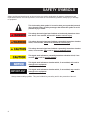
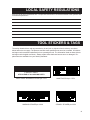
PP10
HYDRAULIC POST PULLER
Safety and Operation
User’s Manual
SERIOUS INJURY OR DEATH COULD
RESULT FROM THE IMPROPER REPAIR OR SERVICE OF THIS TOOL.
© 2006, THE STANLEY WORKS, ALL RIGHTS RESERVED
OPS USA
59020 - 5/2006 Ver 3
REPAIRS AND / OR SERVICE TO THIS
TOOL MUST ONLY BE DONE BY
AN AUTHORIZED AND CERTIFIED
DEALER.
INDEX
Accessories ..........................................................................................................................15
Index (this page) ....................................................................................................................1
Hydraulic Hose Requirements ..........................................................................................6 - 7
Hydraulic Requirements .........................................................................................................8
Operation ...............................................................................................................................9
Parts Drawing....................................................................................................................... 11
Parts List ..............................................................................................................................12
Safety Precautions ............................................................................................................2 - 3
Specifications .......................................................................................................................13
Tool Stickers and Tags ......................................................................................................4 - 5
Troubleshooting ...................................................................................................................10
Warranty ...............................................................................................................................14
SERVICING THE PP10 POST PULLER: This manual contains safety, operation, service and routine maintenance instructions. Stanley Hydraulic Tools recommends that servicing of hydraulic
tools, other than routine maintenance, must be performed by an authorized and certified dealer.
Please read the following warning.
SERIOUS INJURY OR DEATH COULD RESULT FROM THE IMPROPER
REPAIR OR SERVICE OF THIS TOOL.
REPAIRS AND / OR SERVICE TO THIS TOOL MUST ONLY BE DONE
BY AN AUTHORIZED AND CERTIFIED DEALER.
1
SAFETY PRECAUTIONS
Tool operators and maintenance personnel must always comply with the safety precautions given in this
manual and on the stickers and tags attached to the tool and hose.
These safety precautions are given for your safety. Review them carefully before operating the tool and
before performing general maintenance or repairs.
Supervising personnel should develop additional precautions relating to the specific work area and local
safety regulations. If so, place the added precautions in the space provided on page 3.
GENERAL SAFETY PRECAUTIONS
The models PP10 Hydraulic Post Puller will provide safe and dependable service if operated in accordance with the instructions given in this manual. Read and understand this manual and any stickers and
tags attached to the PP10 before operation. Failure to do so could result in personal injury or equipment
damage.
• Operator must start in a work area without bystanders. The operator must be familiar with all prohibited work areas such as excessive slopes and dangerous terrain conditions.
• Establish a training program for all operators to ensure safe operation.
• Do not operate the tool unless thoroughly trained or under the supervision of an instructor.
• Always wear safety equipment such as goggles, ear and head protection, and safety shoes at all times
when operating the tool.
• Do not inspect or clean the tool while the hydraulic power source is connected. Accidental engagement of the tool can cause serious injury.
• Always connect hoses to the tool hose couplers before energizing the hydraulic power source. Be
sure all hose connections are tight.
• Do not operate the tool at oil temperatures above 140°F/60°C. Operation at higher temperatures can
cause higher than normal temperatures at the tool which can result in operator discomfort.
• Do not operate a damaged, improperly adjusted, or incompletely assembled tool.
• Stay clear of all moving parts.
• Never wear loose clothing that can get entangled in the working parts of the tool.
• To avoid personal injury or equipment damage, all tool repair, maintenance and service must only be
performed by authorized and properly trained personnel.
• System pressure hose must always be connected to the tool “IN” or “P” port and system return hose
must be connected to the tool “OUT” or “T” port. Reversing connections or reversing flow to the tool
can
result in severe personal injury.
• Never use tools near energized transmission lines. Know the location of buried or covered services
before starting your work.
2
SAFETY SYMBOLS
Safety symbols and signal words, as shown below, are used to emphasize all operator, maintenance and
repair actions which, if not strictly followed, could result in a life-threatening situation, bodily injury or damage
to equipment.
This is the safety alert symbol. It is used to alert you to potential personal
injury hazards. Obey all safety messages that follow this symbol to avoid
possible injury or death.
This safety alert and signal word indicate an imminently hazardous situation which, if not avoided, will result in death or serious injury.
This safety alert and signal word indicate a potentially hazardous situation
which, if not avoided, could result in death or serious injury.
This safety alert and signal word indicate a potentially hazardous situation
which, if not avoided, may result in minor or moderate injury.
This signal word indicates a potentially hazardous situation which, if not
avoided, may result in property damage.
This signal word indicates a situation which, if not avoided, will result in
damage to the equipment.
IMPORTANT
This signal word indicates a situation which, if not avoided, may result in
damage to the equipment.
Always observe safety symbols. They are included for your safety and for the protection of the tool.
3
LOCAL SAFETY REGULATIONS
Enter any local safety regulations here. Keep these instructions in an area accessible to the operator and
maintenance personnel.
TOOL STICKERS & TAGS
The safety related stickers and tags attached to the tool prior to shipment from the factory are shown
below and on the next page. The pressure and flow rates specified must never be exceeded. All stickers
and tags must be read and understood prior to operating the tool. The information listed on these stickers
and tags must be legible at all times. Always replace those that have become worn or damaged. Replacements are available from your Stanley distributor.
PINCH POINT
STAY CLEAR OF ALL MOVING PARTS
PINCH POINT WARNING STICKER p/n 17572
WARNING STICKER p/n 35210
NAME TAG PP10 p/n 17573
STANLEY STICKER p/n 05152
4
TOOL STICKERS & TAGS Continued. . .
GPM/PRESSURE STICKER
p/n 16599
WARNING STICKER p/n 35210
STANLEY STICKER p/n 05152
STANLEY STICKER p/n 05152
PINCH POINT WARNING
STICKER p/n 17572
PINCH POINT WARNING
STICKER p/n 17572
NAME TAG PP10 p/n 17573
GPM/PRESSURE STICKER
p/n 16599
1. FAILURE TO USE HYDRAULIC HOSE LABELED AND CERTIFIED
AS NON-CONDUCTIVE WHEN USING HYDRAULIC TOOLS
ON OR NEAR ELECTRICAL LINES MAY RESULT IN DEATH
OR SERIOUS INJURY.
BEFORE USING HOSE LABELED AND CERTIFIED AS NONCONDUCTIVE ON OR NEAR ELECTRIC LINES BE SURE THE
HOSE IS MAINTAINED AS NON-CONDUCTIVE. THE HOSE
SHOULD BE REGULARLY TESTED FOR ELECTRIC CURRENT
LEAKAGE IN ACCORDANCE WITH YOUR SAFETY DEPARTMENT INSTRUCTIONS.
2. A HYDRAULIC LEAK OR BURST MAY CAUSE OIL INJECTION
INTO THE BODY OR CAUSE OTHER SEVERE PERSONAL
INJURY.
The safety tag (p/n
15875) at right is attached
to the tool when shipped
from the factory. Read
and understand the safety
instructions listed on this
tag before removal. We
suggest you retain this tag
and attach it to the tool
when not in use.
A
DO NOT EXCEED SPECIFIED FLOW AND PRESSURE FOR
THIS TOOL. EXCESS FLOW OR PRESSURE MAY CAUSE A
LEAK OR BURST.
B DO NOT EXCEED RATED WORKING PRESSURE OF HYDRAU
LIC HOSE USED WITH THIS
TOOL. EXCESS PRESSURE MAY
CAUSE A LEAK OR BURST.
C CHECK TOOL HOSE COUPLERS AND CONNECTORS DAILY
FOR LEAKS. DO NOT FEEL FOR LEAKS WITH YOUR
HANDS.
CONTACT WITH A LEAK MAY
D DO NOT LIFT OR CARRY TOOL BY THE HOSES. DO
NOT ABUSE HOSE. DO NOT USE KINKED, TORN OR
DAMAGED HOSE.
3. MAKE SURE HYDRAULIC HOSES ARE PROPERLY CONNECTED
TO THE TOOL BEFORE PRESSURING SYSTEM. SYSTEM
PRESSURE HOSE MUST ALWAYS BE CONNECTED TO TOOL
“IN” PORT. SYSTEM RETURN HOSE MUST ALWAYS BE
CONNECTED TO TOOL “OUT” PORT. REVERSING CONNECTIONS MAY CAUSE REVERSE TOOL OPERATION WHICH CAN
RESULT IN SEVERE PERSONAL INJURY.
4. DO NOT CONNECT OPEN-CENTER TOOLS TO CLOSED-CENTER HYDRAULIC SYSTEMS. THIS MAY RESULT IN LOSS OF
OTHER HYDRAULIC FUNCTIONS POWERED BY THE SAME
SYSTEM AND/OR SEVERE PERSONAL INJURY.
5. BYSTANDERS MAY BE INJURED IN YOUR WORK AREA. KEEP
BYSTANDERS CLEAR OF YOUR WORK AREA.
6. WEAR HEARING, EYE, FOOT, HAND AND HEAD PROTECTION.
7. TO AVOID PERSONAL INJURY OR EQUIPMENT DAMAGE, ALL
TOOL REPAIR MAINTENANCE AND SERVICE MUST ONLY BE
PERFORMED BY AUTHORIZED AND PROPERLY TRAINED
PERSONNEL.
IMPORTANT
IMPORTANT
READ OPERATION MANUAL AND
SAFETY INSTRUCTIONS FOR THIS
TOOL BEFORE USING IT.
READ OPERATION MANUAL AND
SAFETY INSTRUCTIONS FOR THIS
TOOL BEFORE USING IT.
USE ONLY PARTS AND REPAIR
PROCEDURES APPROVED BY
STANLEY AND DESCRIBED IN THE OPERATION MANUAL.
USE ONLY PARTS AND REPAIR
PROCEDURES APPROVED BY
STANLEY AND DESCRIBED IN THE OPERATION MANUAL.
TAG TO BE REMOVED ONLY BY
TOOL OPERATOR.
TAG TO BE REMOVED ONLY BY
TOOL OPERATOR.
SEE OTHER SIDE
SEE OTHER SIDE
SAFETY TAG P/N 15875 (shown smaller than actual size)
5
TOOL HOSE INFORMATION
HOSE TYPES
The rated working pressure of the hydraulic hose must be equal to or higher than the relief valve setting on the
hydraulic system.There are three types of hydraulic hose that meet this requirement and are authorized for use
with Stanley Hydraulic Tools. They are:
Certified non-conductive - constructed of thermoplastic or synthetic rubber inner tube, synthetic fiber
braid reinforcement, and weather resistant thermoplastic or synthetic rubber cover. Hose labeled certified nonconductive is the only hose authorized for use near electrical conductors.
Wire-braided (conductive) - constructed of synthetic rubber inner tube, single or double wire braid reinforcement, and weather resistant synthetic rubber cover. This hose is conductive and must never be used near
electrical conductors.
Fabric-braided (not certified or labeled non-conductive) - constucted of thermoplastic or synthetic rubber
inner tube, synthetic fiber braid reinforcement, and weather resistant thermoplastic or synthetic rubber cover. This
hose is not certified non-conductive and must never be used near electrical conductors.
hOSE SAFETY TAGS
To help ensure your safety, the following DANGER tags are attached to all hose purchased from Stanley Hydraulic Tools. DO NOT REMOVE THESE TAGS.
If the information on a tag is illegible because of wear or damage, replace the tag immediately. A new tag may be
obtained from your Stanley Distributor.
D A N G E R
D A N G E R
1 FAILURE TO USE HYDRAULIC HOSE LABELED AND CERTIFIED AS NON-CONDUCTIVE
WHEN USING HYDRAULIC TOOLS ON OR NEAR ELECTRIC LINES MAYRESULT IN DEATH
OR SERIOUS INJURY.
FOR PROPER AND SAFE OPERATION MAKE SURE THAT YOU HAVE BEEN PROPERLY
TRAINED IN CORRECT PROCEDURES REQUIRED FOR WORK ON OR AROUND
ELECTRIC LINES.
2. BEFORE USING HYDRAULIC HOSE LABELED AND CERTIFIED AS NON-CONDUCTIVE ON
OR NEAR ELECTRIC LINES. WIPE THE ENTIRE LENGTH OF THE HOSE AND FITTING
WITH A CLEAN DRY ABSORBENT CLOTH TO REMOVE DIRT AND MOSISTURE AND TEST
HOSE FOR MAXIMUM ALLOWABLE CURRENT LEAKAGE IN ACCORDANCE WITH SAFETY
DEPARTMENT INSTRUCTIONS.
3. DO NOT EXCEED HOSE WORKING PRESSURE OR ABUSE HOSE. IMPROPER USE OR
HANDLING OF HOSE COULD RESULT IN BURST OR OTHER HOSE FAILURE. KEEP
HOSE AS FAR AWAY AS POSSIBLE FROM BODY AND DO NOT PERMIT DIRECT CONTACT
DURING USE. CONTACT AT THE BURST CAN CAUSE BODILY INJECTION AND SEVERE
PERSONAL INJURY.
4. HANDLE AND ROUTE HOSE CAREFULLY TO AVOID KINKING, ABRASION, CUTTING, OR
CONTACT WITH HIGH TEMPERATURE SURFACES. DO NOT USE IF KINKED. DO NOT USE
HOSE TO PULL OR LIFT TOOLS, POWER UNITS, ETC.
5. CHECK ENTIRE HOSE FOR CUTS CRACKS LEAKS ABRASIONS, BULGES, OR DAMAGE TO
COUPLINGS IF ANY OF THESE CONDITIONS EXIST, REPLACE THE HOSE IMMEDIATELY.
NEVER USE TAPE OR ANY DEVICE TO ATTEMPT TO MEND THE HOSE.
6. AFTER EACH USE STORE IN A CLEAN DRY AREA.
SIDE 1
3
DO NOT REMOVE THIS TAG
DO NOT REMOVE THIS TAG
THE TAG SHOWN BELOW IS ATTACHED TO “CERTIFIED NON-CONDUCTIVE” HOSE
SIDE 2
(shown smaller than actual size)
D A N G E R
D A N G E R
1 DO NOT USE THIS HYDRAULIC HOSE ON OR NEAR ELECTRIC LINES. THIS HOSE IS
NOT LABELED OR CERTIFIED AS NON-CONDUCTIVE. USING THIS HOSE ON OR NEAR
ELECTRICAL LINES MAY RESULT IN DEATH OR SERIOUS INJURY.
2. FOR PROPER AND SAFE OPERATION MAKE SURE THAT YOU HAVE BEEN PROPERLY
TRAINED IN CORRECT PROCEDURES REQUIRED FOR WORK ON OR AROUND
ELECTRIC LINES.
5. CHECK ENTIRE HOSE FOR CUTS CRACKS LEAKS ABRASIONS, BULGES, OR DAMAGE TO
COUPLINGS IF ANY OF THESE CONDITIONS EXIST, REPLACE THE HOSE IMMEDIATELY.
NEVER USE TAPE OR ANY DEVICE TO ATTEMPT TO MEND THE HOSE.
6. AFTER EACH USE STORE IN A CLEAN DRY AREA.
3. DO NOT EXCEED HOSE WORKING PRESSURE OR ABUSE HOSE. IMPROPER USE OR
HANDLING OF HOSE COULD RESULT IN BURST OR OTHER HOSE FAILURE. KEEP
HOSE AS FAR AWAY AS POSSIBLE FROM BODY AND DO NOT PERMIT DIRECT CONTACT
DURING USE. CONTACT AT THE BURST CAN CAUSE BODILY INJECTION AND SEVERE
PERSONAL INJURY.
4. HANDLE AND ROUTE HOSE CAREFULLY TO AVOID KINKING, CUTTING, OR CONTACT
WITH HIGH TEMPERATURE SURFACES. DO NOT USE IF KINKED. DO NOT USE HOSE TO
PULL OR LIFT TOOLS, POWER UNITS, ETC.
DO NOT REMOVE THIS TAG
DO NOT REMOVE THIS TAG
The tag shown below is attached to “conductive” hose.
SEE OTHER SIDE
SIDE 1
SIDE 2
(shown smaller than actual size)
6
7
51-100
100-300
up to 50
51-100
100-200
up to 25
26-100
19-30
19-30
34-45
34-45
34-45
49-60
49-60
5-8
5-8
9-12
9-12
9-12
13-16
13-16
8-30
up to 8
30-60
15-30
up to 15
30-90
15-30
up to 15
METERS
25.4
19
1
19
3/4
16
5/8
3/4
25.4
19
3/4
1
19
16
5/8
3/4
16
5/8
19
16
5/8
3/4
16
13
MM
5/8
1/2
INCH
Inside Diameter
SAE 100R1-16
SAE 100R17-12
SAE 100R1-12
SAE 100R2-10
SAE 100R1-16
SAE 100R17-12
SAE 100R1-16
SAE 100R2-10
SAE 100R17-10
SAE 100R1-12
SAE 100R2-10
SAE 100R17-10
SAE 100R17-8
Wire Braid
Hose Spec
PRESSURE
TOOL
RETURN
1000
3000
1250
2750
1000
3000
1000
2750
3000
1250
2750
3000
3000
PSI
69
230
86
190
69
230
69
190
230
86
190
230
230
BAR
Working Pressure
Typical Hose Connections
FLOW>>>
RETURN
MALE PIPE HOSE END
<<<FLOW
PRESSURE
Return
Pressure
Return
Pressure
Return
Pressure
Return
Pressure
Both
Return
Pressure
Both
Both
USE
MALE PIPE HOSE END
NA
NA
SAE 100R7-12
SAE 100R8-10
NA
NA
SAE 100R7-12
SAE 100R8-10
SAE 100R8-10
SAE 100R7-12
SAE 100R8-10
SAE 100R8-10
SAE 100R7-8
Fiber Braid
Hose Spec
NA
NA
1250
2750
NA
NA
1250
2750
2750
1250
2750
2750
2000
PSI
NA
NA
86
190
NA
NA
86
190
190
86
190
190
140
BAR
Operating Pressure
PRESSURE
H.T.M.A. MALE QUICK
DISCONNECT COUPLER
ADAPTER OR HOSE WHIPS, 3/8
INCH MALE PIPE x -8 SAE O-RING
H.T.M.A. FEMALE QUICK
DISCONNECT COUPLER
NOTE: SAE 100R16 may be used in place of SAE100R2
FEET
up to 50
LPM
19-30
5-8
Each Hose Length
GPM
Oil Flow
Tool To Circuit Hose Recommendations
HYDRAULIC CIRCUIT
CONTROL PANEL
RETURN
HYDRAULIC REQUIREMENTS
ambient temperature.
IMPORTANT
In addition to the Safety Precautions on pages 2 thru 5 of this
manual, observe the following
for equipment protection and
care.
• Do not exceed the rated limits or use the tool for
applications beyond its design capacity.
• Always keep critical tool markings, such as labels
and warning stickers legible.
• Always replace hoses, couplings and other parts
with replacement parts recommended by Stanley
Hydraulic Tools. Supply hoses must have a minimum working pressure rating of 2500 psi/175 bar.
• The hydraulic system should have a minimum
of 25 micron filtration. Recommend using filter
elements sized for a flow of at least 30 gpm/114
lpm for cold temperature startup and maximum dirt
holding capacity.
• The hydraulic fluid used should have a viscosity
between 100 and 400 ssu/20 and 82 centistokes
at the maximum and minimum expected operating temperatures. Petroleum base hydraulic fluids
with antiwear properties and a viscosity index over
140 ssu/28 centistokes will meet the recommended
requirements over a wide range of operating temperatures.
• The recommended hose size is .500 inch/12 mm
I.D. up to 50 ft/15 m long and .625 inch/16 mm I.D.
minimum up to 100 ft/30 m long.
• Permit only experienced personnel to perform
tool repair.
• Be sure to wipe all couplers clean before connecting. Use only lint-free cloths.
• The hydraulic circuit control valve must be in
the “OFF” position when coupling or uncoupling
the tool. Failure to do so may result in damage to
the quick couplers and cause overheating of the
hydraulic system.
• Check fastener tightness often and before each
use daily.
Failure to use hydraulic hose labeled and
certified as non-conductive when using
hydraulic tools on or near electric lines may
result in death or serious injury.
Make sure that you have been properly
trained in correct procedures required for
work on or around electric lines.
• Quick disconnect couplings must conform to
NFPA T3.20,15/HTMA specifications.
HYDRAULIC SYSTEM
REQUIREMENTS
• The hydraulic system should provide a flow of
3-9 gpm/11-34 lpm at an operating pressure of
1000-2000 psi/70-140 bar. Recommended relief
valve setting is 2100-2250 psi/145-155 bar.
• The system should have no more than 250
psi/17 bar backpressure measured at the tool end
of the operating hoses.
• The hydraulic system should have enough heat
rejection capacity to limit the maximum oil temperature to 140°F/60°C at the maximum expected
8
OPERATION
PREOPERATION
PROCEDURES
difficult to connect. When possible, connect
the free ends of operating hoses together.
4. Observe all safety precautions.
PREPARATION FOR INITIAL
USE
Each unit as shipped has no special unpacking or
assembly requirements prior to usage. Inspection
to assure the unit was not damaged in shipping
and does not contain packing debris is all that is
required.
CHECK HYDRAULIC POWER
SOURCE
1. Using a calibrated flowmeter and pressure
gauge, check that the hydraulic power source develops a flow of 3-9 gpm/11-34 lpm at 2000
psi/140 bar.
2. Make certain the hydraulic power source is
equipped with a relief valve set to open at 21002250 psi/145-155 bar minimum.
5. Move the hydraulic circuit control valve to the
“ON” position to operate the tool.
TOOL OPERATION
1. Observe all safety precautions.
2. For flanged posts, position the base weldment
on a flat surface with the post engaged in the jaws
of the tool.
3. For solid or square posts, position the base
weldment on a flat surface and wrap a chain
around the post. Place the chain in the slots on the
post puller frame.
4. Actuate the control lever from the “NEUTRAL”
position to the “UP” position until the post raises
approximately eight inches.
1. There should be no signs of leaks.
5. Move the control lever from the “UP” position
past the “NEUTRAL” position to the “DOWN” position. This releases the jaws (or chain) from the post
and lowers the lift frame weldment down to the
base weldment (bottom of post).
2. The tool should be clean, with all fittings and
fasteners tight.
6. Repeat steps one through five until the post is
fully removed.
CHECK TOOL
CONNECT HOSES
1. Wipe all hose couplers with a clean lint-free
cloth before making connections.
2. Connect the hoses from the hydraulic power
source to the tool fittings or quick disconnects. It
is a good practice to connect the return hose first
and disconnect it last to minimize or avoid trapped
pressure within the tool.
If the post puller is to be used during cold weather,
preheat the hydraulic fluid at low engine speed.
When using the normally recommended fluids,
fluid temperature should be at or above 50 °F/10°C
(400 ssu/82 centistokes) before use.
3. Observe flow indicators stamped on hose couplers to be sure that oil will flow in the proper direction. The female coupler is the inlet coupler.
Damage to the hydraulic system or post puller can
result from use with fluid that is too viscous or thick.
NOTE: The pressure increase in uncoupled
hoses left in the sun may result in making them
9
COLD WEATHER
OPERATION
TROUBLESHOOTING
If symptoms of poor performance develop, the following chart can be used as a guide to correct the
problem.
When diagnosing faults in operation of the Post
Puller, always check that the hydraulic power
PROBLEM
Post Puller does not run.
Post Puller does not pull.
effectively.
Post Puller operates slow.
Post Puller gets hot.
source is supplying the correct hydraulic flow and
pressure to the post puller as listed in the table.
Use a flowmeter known to be accurate. Check
the flow with the hydraulic oil temperature at least
80°F/27°C.
POSSIBLE CAUSE
SOLUTION
Power unit not functioning.
Check power unit for proper flow and
pressure (3-9 gpm/11-34 lpm, 2000
psi/140 bar).
Coupler or hoses blocked.
Remove restriction.
Mechanical failure of lift cylinder
assembly.
Disassemble post puller and inspect
for damaged parts.
Power unit not functioning.
Check power unit for proper pressure
(2000 psi/140 bar).
Couplers or hoses blocked.
Remove restriction.
Low gpm supply from power unit
Check power source for proper flow
(3-9 gpm/11-34 lpm).
Couplers or hoses blocked.
Remove restriction.
Relief valve set too low.
Adjust relief valve to 2100-2250 psi
/145-155 bar.
Hot fluid going through tool.
Check power unit. Make sure the flow
rate is not too high causing part of the
fluid to go through the relief valve.
Provide cooler to maintain proper
fluid temperature (140°F/60°C max).
Check relief valve setting.
Eliminate flow control devices.
10
11
PR41 PARTS LIST
Item
No
Part
No
Qty
1
2
3
17533
04985
17553
1
2
2
4
00166
1
5
6
7
8
9
10
11
12
13
14
15
16
17
18
17526
03127
09642
09647
09790
17546
17536
17552
17554
04984
17550
371500
01751
06736
1
1
1
1
2
1
1
1
2
1
1
8
2
4
19
20
21
22
23
24
25
26
27
28
29
30
31
32
33
34
35
01752
35518
18514
17556
17557
17558
17537
17538
01532
17545
17549
17544
17529
17559
17534
17540
17543
33452
17542
33453
17541
00569
03031
16599
05152
17572
17573
19220
19221
1
1
1
2
1
1
4
1
1
1
1
1
1
2
2
2
1
1
1
1
1
2
2
1
2
2
1
1
1
36
37
38
39
40
41
42
43
44
45
Description
T-bar
Spring Washer
Shoulder Screw, 3/4 x 3/4 Hex
Socket Head
Retaining Ring, 1.850 Heavy
Duty (Internal)
Seal Retainer
Rod Wiper
Washer
Rod Seal
O-ring, 2-1/4 x 2-1/2 x 1/8
Piston Rod
Cylinder
Piston
Wear Ring
Elastic Stop Nut, 3/4-16 Hex
Lift Frame Weldment
Elastic Stop Nut, 1/2-13 Hex
O-ring 3/8 x 9/16 x 3/32
Capscrew, 5/16-18 x 2-1/4 Hex
Head
Adapter Fitting
Valve Assembly
Guard Weldment
Elbow
Elbow, 45°-3/8 NPT M-6 Tube
Hose Assembly
Tie Rod
Base Weldment
Elbow, 90°-6 SAE/-6 Tube
Cylinder Base
Cylinder Bearing
Adapter Block
Chain Assy (Accessory Item)
Washer, 7/8 Narrow Type B
Modified Capscrew
Shoulder Screw
Jaw, R.H. (Model PP10100)
Jaw, R.H. (Model PP10100A)
Jaw, L.H. (Model PP10100)
Jaw, L.H. (Model PP10100A)
Pivot Block
Capscrew, 5/16-18 x 1 Hex Hd
Lockwasher, 5/16
GPM Sticker
Stanley Sticker
Pinch Point Warning Sticker
Name Tag
TFE Ring
O-ring
SEAL KIT 19219
Denotes part in seal kit
NOTE: Use Part Number and Part Name
when ordering.
The Following Items Are Not Pictured
35213
2
35149
35212
1
1
24069
1
35210
1
Swivel, Hydraulic Inc.#956P6-P6
(Used on Model PP10100A only)
Post (Model PP10100A only)
Hitch Pin Assy (Model
PP10100A only)
Coupler set (Model PP10100A
only)
Warning Decal (Both Models)
12
SPECIFICATIONS
Capacity (Lift per Stroke)...............................................................................................................8 in./20
cm
Pulling Force........................................................................................................................9800 lbs/4450
kg
Weight..........................................................................................................................................62 lbs/28
kg
Flow Range ....................................................................................................................3-9 gpm/ 11-34 lpm
Pressure Range...................................................................................................................2000 psi/140
bar
Porting..............................................................................................................3/8 NPT Female Pipe
Thread
Connect Size ................................................................................................................90° Elbow 3/8
Note
Weights, dimensions, and operating specifications listed
are subject to change without notice. Where specifications
are critical to your application, please consult the factory.
ACCESSORIES
17529
13
Chain Assy
WARRANTY
Stanley Hydraulic Tools (hereinafter called “Stanley”), subject to the exceptions contained below, warrants new hydraulic tools for a period of one year
from the date of sale to the first retail purchaser, or for a period of 2 years from the shipping date from Stanley, whichever period expires first, to be free
of defects in material and/or workmanship at the time of delivery, and will, at its option, repair or replace any tool or part of a tool, or new part, which is
found upon examination by a Stanley authorized service outlet or by Stanley’s factory in Milwaukie, Oregon to be DEFECTIVE IN MATERIAL AND/OR
WORKMANSHIP.
EXCEPTIONS FROM WARRANTY
NEW PARTS: New parts which are obtained individually are warranted, subject to the exceptions herein, to be free of defects in material and/or workmanship at the time of delivery and for a period of 6 months after the date of first usage. Seals and diaphragms are warranted to be free of defects
in material and/or workmanship at the time of delivery and for a period of 6 months after the date of first usage or 2 years after the date of delivery,
whichever period expires first. Warranty for new parts is limited to replacement of defective parts only. Labor is not covered.
FREIGHT COSTS: Freight costs to return parts to Stanley, if requested by Stanley for the purpose of evaluating a warranty claim for warranty credit,
are covered under this policy if the claimed part or parts are approved for warranty credit. Freight costs for any part or parts which are not approved for
warranty credit will be the responsibility of the individual.
SEALS & DIAPHRAGMS: Seals and diaphragms installed in new tools are warranted to be free of defects in material and/or workmanship for a period
of 6 months after the date of first usage, or for a period of 2 years from the shipping date from Stanley, whichever period expires first.
CUTTING ACCESSORIES: Cutting accessories such as breaker tool bits are warranted to be free of defects in material and or workmanship at the
time of delivery only.
ITEMS PRODUCED BY OTHER MANUFACTURERS: Components which are not manufactured by Stanley and are warranted by their respective
manufacturers.
a. Costs incurred to remove a Stanley manufactured component in order to service an item manufactured by other
manufacturers.
ALTERATIONS & MODIFICATIONS: Alterations or modifications to any tool or part. All obligations under this warranty shall be terminated if the new
tool or part is altered or modified in any way.
NORMAL WEAR: any failure or performance deficiency attributable to normal wear and tear such as tool bushings, retaining pins, wear plates, bumpers, retaining rings and plugs, rubber bushings, recoil springs, etc.
INCIDENTAL/CONSEQUENTIAL DAMAGES: To the fullest extent permitted by applicable law, in no event will STANLEY be liable for any incidental,
consequential or special damages and/or expenses.
FREIGHT DAMAGE: Damage caused by improper storage or freight handling.
LOSS TIME: Loss of operating time to the user while the tool(s) is out of service.
IMPROPER OPERATION: Any failure or performance deficiency attributable to a failure to follow the guidelines and/or procedures as outlined in the
tool’s operation and maintenance manual.
MAINTENANCE: Any failure or performance deficiency attributable to not maintaining the tool(s) in good operating condition as outlined in the Operation and Maintenance Manual.
HYDRAULIC PRESSURE & FLOW, HEAT, TYPE OF FLUID: Any failure or performance deficiency attributable to excess hydraulic pressure, excess
hydraulic back-pressure, excess hydraulic flow, excessive heat, or incorrect hydraulic fluid.
REPAIRS OR ALTERATIONS: Any failure or performance deficiency attributable to repairs by anyone which in Stanley’s sole judgement caused or
contributed to the failure or deficiency.
MIS-APPLICATION: Any failure or performance deficiency attributable to mis-application. “Mis-application” is defined as usage of products for which
they were not originally intended or usage of products in such a matter which exposes them to abuse or accident, without first obtaining the written
consent of Stanley. PERMISSION TO APPLY ANY PRODUCT FOR WHICH IT WAS NOT ORIGINALLY INTENDED CAN ONLY BE OBTAINED FROM
STANLEY ENGINEERING.
WARRANTY REGISTRATION: STANLEY ASSUMES NO LIABILITY FOR WARRANTY CLAIMS SUBMITTED FOR WHICH NO TOOL REGISTRATION IS ON RECORD. In the event a warranty claim is submitted and no tool registration is on record, no warranty credit will be issued without first
receiving documentation which proves the sale of the tool or the tools’ first date of usage. The term “DOCUMENTATION” as used in this paragraph
is defined as a bill of sale, or letter of intent from the first retail customer. A WARRANTY REGISTRATION FORM THAT IS NOT ALSO ON RECORD
WITH STANLEY WILL NOT BE ACCEPTED AS “DOCUMENTATION”.
NO ADDITIONAL WARRANTIES OR REPRESENTATIONS
This limited warranty and the obligation of Stanley thereunder is in lieu of all other warranties, expressed or implied including merchantability or fitness
for a particular purpose except for that provided herein. There is no other warranty. This warranty gives the purchaser specific legal rights and
other rights may be available which might vary depending upon applicable law.
14
Hydraulic Tools
3810 S.E. Naef Road
Milwaukie, Oregon 97267-5698
Phone: 503/659-5660
Fax: 503/652-1780