1
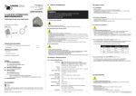
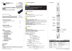
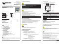
Leader Light s.r.o.
M.Gorkeho 33
SK-052 01 Spisska Nova Ves
Slovakia
www.leaderlight.eu
USER MANUAL
LL LED Z-POWER DRIVER
LL42 100 LL42 200
01
SAFETY INFORMATION
02.2 Product labelling
Dip options “100“ “10“ “1“ » Rotating DIP address 000÷511
Control Data
Power Supply DC 24V
6PIN LINE
Control LEDs
WARNING!!!
Carefully read before installing, powering or servicing.
Nothing to do if anything misunderstand!
Only for professional use!
COMPLIMENTS ON YOUR PURCHASE!
01.1 Safety instructions
4 Groups
6PIN LINE
All dimensions are in milimeters
- Shut down power before installation or maintenance.
- Do not modify, alter, or attempt to service the LeaderLight appliance.
Doing so will void the warranty.
- Use only with Leader Light LED Z-POWER or TOP LED products.
- Use only with recomended by Leader Light DC power supply.
- We recomended the earth on the bottom of box has to be connected!
- The electric connection, repairs and servicing must be carried out by a qualified employee.
- Do not connect this unit to any dimmers.
- AC power for DC power supply must complies with local building and electrical rules.
- AC power has to have both overload and short circuit protection.
73,5
107
105,4
Operate only with DC 24V source with 0-100% current output!
Control LEDs Indication
POWER
LED
INDICATION
POWER (Red)
blinking – 2Hz
OK - inside fixture is everything correct
DATA (Green)
light off
NO DMX512 signal
DATA (Green)
blinking – 4Hz
OK- income correct DMX512 signal
DATA (Green)
fast blinking
NON correct digital signal
alternate blinking
Autotest function
DATA
STATUS
POWER (Red)
DATA (Green)
01.2 Operating determination
Following items are included:
- LL LED Z-POWER DRIVER
1 pc.
- 6PIN LINE connectors
5 pcs.
- User manual
1 pc.
Additional items needed:
- Data cable
- DC power supply 24V
- The unit operate only with Leader Light LED Z-POWER and TOP LED products.
- This product was designed for indoor use only.
- If the unit has been exposed to drastic temperature fluctuation (e.g. after transportation),
do not switch it on immediately. The arising condensation water might damage your unit.
Leave the unit switched off until it has reached room temperature.
- Please make sure that the unit is not exposed to extreme heat, moisture or dust.
- The unit operate only after checking, that the housing is firmly closed and all screws are
tightly fastened.
- Unprofessional operation creates the most damages!
- By product transport use the original packaging.
ENVIRONMENT
Do not throw away the appliance with the normal household waste at the end of its life,
but hand it in at an official collection point for recycling. By doing this, you help to preserve
the environment.
©MMVIII - Leader Light – All right reserved
03.1 Unpacking
- Unpack carefully.
- This is electronic equipment and should be handled carefully.
- Damaged delivered package or if are any mechanical parts broken – it must be claim
immediately by the transport company.
Photo pictures as evidence are valuable for future claim.
03.2 Physical installation
01.3 Fire prevention
- Loading capacity of bearing area has to be at least 10 times the weight of all device clusters.
Content:
01 SAFETY INFORMATION
01.1 Safety instructions
01.2 Operating determinations
01.3 Fire prevention
02 PRODUCT SPECIFICATION
02.1 Technical Specification
02.2 Product labelling
03 INSTALLATION
03.1 Unpacking
03.2 Physical installation
03.3 Connecting to DC power supply
03.4 Installation factors
03.5 Connection to the DC power input
03.6 Connection possibility
03.7 DMX channels
04 MAINTENANCE AND SERVICE INSTRUCTIONS
03 INSTALLATION
03.3 Connecting to DC power supply
- Follow all safety consideration.
- Device never shield – minimum distance around must be 100mm (4 in.).
- Allowing max. ambient temperature is 40°C (104°F).
- You can suffer a dangerous electric shock by using a high voltage AC/DC power
supply - by touching AC/DC power supply the wires inside the unit!
02 PRODUCT SPECIFICATION
03.4 Installation factors
02.1 Technical Specification
Power connection:
Control data connection:
Net weight:
Ambient temp.(Ta):
Control:
Dimensions LxWxH:
Installation:
In: 0-16A, 24V DC, max. 16A
Out: DC 24V PWM DIM
DMX In/Out: 6pin LINE connector
12x LED Out: 4 groups each 3 channels
1,0 kg
-10°C ~ +40°C except outdoor box with cooling and
heating module
Protocol: USITT DMX512
Control options: DMX, Auto-trigger
Operation modes: Stand alone
Programs: test program
107mm x 105,4mm x 73,5mm
DIN installation
Edition: A - 2008
- For any indoor and outdoor installation inside the installation box must be add +20mm
each side and must be add ventilation modul.
Specialy for outdoor installation must be add heating modul, if the outdoor temperature
is less then 0°C any time!
03.5 Connection to the DC power input
- The LL LED Z-POWER DRIVER is equipped only for DC24V operating use.
- TOTAL current input is limited for 16A !!!
- We recomended the earth on the bottom of box has to be connected!
03.6 Connection possibility
- Shut down power supply before installation of DRIVER to LED fixtures.
- Total current output of DRIVER is limited for maximum 16A!
- Maximum LED fixtures connection to the LL LED PWM DRIVER see on figure 1.1.
If you have any question please, contact [email protected]
03.7 DMX channels
- Shut down power supply before installation of DRIVER to LED fixtures.
- Total current output of DRIVER is limited for maximum 16A!
Mode 1: DIP2=Off and DIP3=Off
Mode 2: DIP2=Off and DIP3=On
channel 1 =
Red 1
channel 1 =
Red 1
channel 2 =
Green 1
channel 2 =
Green 1
channel 3 =
Blue 1
channel 3 =
Blue 1
channel 4 =
Red 2
channel 4 =
White 1
channel 5 =
Green 2
channel 5 =
Red 2
channel 6 =
Blue 2
channel 6 =
Green 2
1.1.
Group 1
Group 2
1,4 1,4 1,4
1,4 1,4 1,4
1,4
1,4 1,4 1,4 1,4 1,4
LL LED LINE
1,4 1,4 1,4
1,4 1,4 1,4
1,4
1,4 1,4 1,4 1,4 1,4
Group 3
1,4 1,4 1,4
1,4 1,4 1,4
Group 4
1,4 1,4 1,4
1,4
4 x RGB
3 x RGBW
2 x RGBAW
maximal fitting amound
per LL LED DRIVER
Ic (A)*
RGB/AWB
3x 0,35 = 1,05A
4
4
4
4
15
!max.16A
RGB/AWB
3x 0,70 = 2,10A
2
2
2
2
7
!max.16A
RGB/AWB
3x 1,40 = 4,20A
1
1
1
1
3
!max.16A
channel 7 =
Red 3
channel 7 =
Blue 2
channel 8 =
Green 3
channel 8 =
White 2
OneColour
channel 9 =
Blue 3
channel 9 =
Red 3
R/G/B/A/W/N
1x 0,35 = 0,35A
4
4
4
4
4
4
4
4
4
4
4
4
45
!max.16A
channel 10 =
Red 4
channel 10 =
Green 3
R/G/B/A/W/N
1x 0,70 = 0,70A
2
2
2
2
2
2
2
2
2
2
2
2
22
!max.16A
channel 11 =
Green 4
channel 11 =
Blue 3
R/G/B/A/W/N
1x 1,40 = 1,40A
1
1
1
1
1
1
1
1
1
1
1
1
11
!max.16A
channel 12 =
Blue 4
channel 12 =
White 3
LL LED TopLED
RGB
3x 0,02 = 0,06A
70
70
70
RGBW
4x 0,02 = 0,08A
70
70
70
RGBAW
5x 0,02 = 0,10A
70
70
70
266
!max.16A
200
!max.16A
140
!max.16A
Mode 3: DIP2=Off and DIP3=On
Mode 4: DIP2=On and DIP3=On
channel 1 =
Red 1
channel 1 =
channel 2 =
Green 1
channel 2 =
Green 1
RGB/AWB
3x 0,35 = 1,05A
6x4
6x4
6x4
6x4
15x6
!max.16A
channel 3 =
Blue 1
channel 3 =
Blue 1
R/A
G/B/W/N
1x 0,35 = 0,35A
6 x 12
6 x 12
6 x 12
6 x 12
45x6
!max.16A
channel 4 =
Amber 1
channel 4 =
White 1
channel 5 =
White 1
channel 5 =
Amber 1
channel 6 =
Red 2
channel 6 =
Red 2
channel 7 =
Green 2
channel 7 =
Green 2
channel 8 =
Blue 2
channel 8 =
Blue 2
channel 9 =
Amber 2
channel 9 =
White 2
channel 10 =
White 2
channel 10 =
Amber 2
Red 1
LL LED Point+Splitter (6 x point)**
Note:
* Ic (A) - current for 1 colour ; ** for each LL LED POINT (RGB/AWB), (R/A), (G/B/W/N) use special LL LED POINT SPLITTER.
Recommended power supply by Leader Light - MW 240/24 - only 10A!
Connection conditions:
• Maximal current on DRIVER is 16A
• Maximal allowed current on each connector terminal is 1,4A
• Never use more fittings as maximal allowed amound
Extention and control functions:
• LL LED Z-POWER DRIVER is calculated only for LL LED products
Amound of channels per LL LED Z-POWER DRIVER:
Dip4=Off, Dip1=Off =>DipBCD:
use rotating switch for DMX start address
(RS1 - “100“, RS2- “10“, RS3- “1“) from 001 to 512
4x
RGB
12 channels
DipBCD=9xx:
AutoTest: fade-over
3x
RGBW
12 channels
DipBCD=8xx:
AutoTest: al channels on 50%
2x
RGBAW
10 channels
Dip1=On:
switch Paralel mode
Dip4=On:
switch UltraSoft curve
Dip2=Off, Dip3=Off:
Mode 1 (12ch) 4xRGB
Dip2=Off, Dip3=On:
Mode 2 (12ch) 3xRGBW
Standard LL cable has following cable cores:
Dip2=On, Dip3=Off:
Mode 3 (10ch) 2xRGBAW
Dip2=On, Dip3=On:
Mode 4 (10ch) 2xRGBWA
RGBAW+Black, or RGB+Black.
Each colour is connected to corresponding colour.
In case AWB: RGB+Black (AWB is connected to RGB).
or many another combinations
04 MAINTENANCE
Group connection possibility
R
G
B
A
W V+
- To tackle all Safety Information- 01!
- Damage caused by inadequate cleaning or maintenance is not coverd by warranty.
- Regular cleaning is demand (dust, dirt, ...).
Maintenance policy:
- Unplug mains befor maintenance and at least 10 minutes cool off.
- Cleanup dust from appliance.
- Use vacuum or dampy duster (warm watter).
- Before reinstalling to check failure-free state – no wet parts!
If you have any question please, contact [email protected]