1
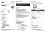
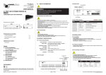
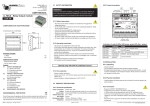
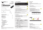
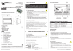
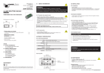
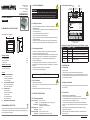
Leader Light s.r.o.
M.Gorkeho 33
SK-052 01 Spisska Nova Ves
Slovakia
www.leaderlight.eu
USER MANUAL
LL ARC DRIVER 12
01 SAFETY INFORMATION
02.2 Product description
DIP
DC 24V
settings
power
Control data
Control
Rotating DIP
6pin line conector
LEDs
“100““10“ “1“
WARNING!!!
Carefully read before installing, powering or servicing. Nothing to
do if anything misunderstand! Installation can be done only by a
qualified professional in accordance with relevant local codes.
D- D+
D- D+
DMX 512
RS 423/232
LL42 100
1234
x100
All dimensions are in millimeters
107
105,4
Package includes:
- LL ARC DRIVER12
1 pc.
- 6pin line connector
5 pcs.
1 pc.
Additional items needed:
- Data and power cables
- 24V DC power supply
Content:
01
SAFETY INFORMATION
01.1 Safety instructions
01.2 Operating restrictions
01.3 Fire protection
02
PRODUCT SPECIFICATION
02.1 Technical specification
02.2 Product description
03
INSTALLATION
03.1 Unpacking
03.2 Physical installation
03.3 Connection
03.4 Installation factors
03.5 DMX channels
04
MAINTENANCE AND SERVICE
ENVIRONMENTAL PROTECTION
Do not throw away the appliance with the normal household waste at the end of
its life, but hand it in at an official collection point for recycling. By doing this, you
help to preserve the environment.
©MMX - Leader Light – All right reserved
D P
A O
T W
A E
R
S/N
DC 24V INPUT, Tmax:40°C
MAX. 16A
GROUP 1
GROUP 2
GROUP 3
R G B A W+V R G B A W+V R G B
GROUP 4
W+V R G B
+V
12x LED PWM output, 4 groups
4x 6pin line conector
Indication of control LEDs (LED power- green,LED data - yellow)
75,4
01.2 Operating restrictions
- User manual
POWER
INPUT
Made in EU
Leader Light s.r.o. Slovakia, 2010
www.leaderlight.eu
[email protected]
- Shut down power before installation or maintenance of equipment or
voltage /data source.
- Do not modify, alter, or attempt to service the LeaderLight appliance. Doing
so will void the warranty.
- Use only the recommended DC voltage source.
- Connect the ground to the bottom of the box!
- Electrical connections, service and maintenance can be performed only by
qualified professional.
- AC power supply of DC power supply must comply with local regulations.
- AC power supply must be protected against overvoltage and short circuits.
73,5
x1 +24V 0V
LL ARC DRIVER
01.1 Safety instructions
COMPLIMENTS ON YOUR PURCHASE!
x10
DIP
CHANNELS
MODE & ADDRESS
- This product is intended to operate only with Leader Light LED products.
- This product was designed for indoor use only!
- If the product has been exposed to drastic temperature fluctuation (e.g. after
transportation), do not switch it on immediately. The arising condensation
water might damage your unit. Leave the unit switched off until it has
reached room temperature.
- Do not operate the product in humid, dusty or too hot/cold environments.
- Before connecting, make sure the product is not damaged, wet, or otherwise
damaged.
- Unprofessional operation creates the most damages!
- For transport use the original packaging.
Operate only with 24V DC stabilized source!
LED
Indication
Status
LED Power
blinking - 2Hz
O.K. - device is working correct
LED Data
not lit
No DMX signal
LED Data
blinking - 4Hz
O.K. - Connected the correct DMX signal
LED Data
fast blinking
ERROR - incorrect digital signal
LED Power &
LED Data
alternating
blinking
function AutoTest
03 INSTALLATION
03.1 Unpacking
- Unpack carefully.
- This is electronic equipment and should be handled carefully.
- Damaged delivered package or if are any mechanical parts broken – it must
be claim immediately by the transport company. Photo pictures as evidence
are valuable for future claim.
01.3 Fire protection
- Follow all safety restrictions.
- Device never cover – the minimum space around the vents must be at least
100mm (4 in.).
- Allowed maximum ambient temperature is 40°C (104°F).
02 PRODUCT SPECIFICATION
02.1 Technical specification
Power connection:
Output:
Control data:
Ambient temp. (Ta):
Net weight:
Dimensions LxWxH:
Installation:
24V DC, max. 16A
12x LED PWM output 24V DC, 4 output groups
Protocol USITT DMX-512
or RS 423/232 LL defined protocol
0°C/+40°C
1,0 kg
107mm x 105,4mm x 79mm
standard DIN installation TS35 – 6DIN
Edition: A - 2010
03.2 Physical installation
- Loading capacity of bearing area has to be at least 10 times the weight of all
device clusters.
03.3 Connection
- Respect all SAFETY INFORMATION 01!
- Connect the ground (earth) to the bottom of the module!
- LL ARC DRIVER12 device may be operated only with 24V DC stabilized
source. Total input current is limited to max. 16A!
- In the case of connecting the power supply with more than a prescribed
voltage you can suffer a dangerous electric shock, inflict damage equipment
or fire.
- Shut down power supply from all devices before installation of LL ARC
DRIVER12 to end devices.
- Maximum number of connected LED luminaries to LL DRIVER12 ARC is
shown in Table 1.1.
If you have any question please, contact [email protected]
1.1.
03.4 Installation Factors
R G B A W +V
R G B A W +V
Group 1
Group 2
- For any indoor and outdoor installation inside the installation box must
be add +100mm to each side and must be add ventilation modul.
- For outdoor installation must be add heating modul, if the outdoor
temperature is less then 0°C any time!
03.5 DMX channels
1,4 1,4 1,4
1,4 1,4 1,4
These informations are subject to change, latest data are on: www.leaderlight.eu
1,4 1,4 1,4
Mode 1: DIP2=Off and DIP3=Off
Mode 2: DIP2=Off and DIP3=On
1,4 1,4 1,4 1,4 1,4
channel 1 =
Red 1
channel 1 =
Red 1
channel 2 =
Green 1
channel 2 =
Green 1
channel 3 =
Blue 1
channel 3 =
Blue 1
channel 4 =
Red 2
channel 4 =
White 1
channel 5 =
Green 2
channel 5 =
Red 2
channel 6 =
Blue 2
channel 6 =
Green 2
channel 7 =
Red 3
channel 7 =
Blue 2
channel 8 =
Green 3
channel 8 =
White 2
channel 9 =
Blue 3
channel 9 =
Red 3
channel 10 =
Red 4
channel 10 =
Green 3
channel 11 =
Green 4
channel 11 =
Blue 3
channel 12 =
Blue 4
channel 12 =
White 3
Mode 3: DIP2=On and DIP3=Off
Mode 4: DIP2=On and DIP3=On
channel 1 =
Red 1
Manual Mode
channel 2 =
Green 1
channel 3 =
Blue 1
channel 4 =
Amber 1
channel 5 =
White 1
channel 6 =
Red 2
channel 7 =
Green 2
channel 8 =
Blue 2
channel 9 =
Amber 2
channel 10 =
White 2
1,4
W +V
Group 3
1,4 1,4 1,4
1,4
R G B
1,4 1,4 1,4
+V
Group 4
1,4 1,4 1,4
w 4 x RGB
1,4
3 x RGBW
1,4 1,4 1,4 1,4 1,4
2 x RGBAW
RGB/AWB
3x 0,35 = 1,05A
4
4
4
4
maximum fitting amound
per LL ARC DRIVER
15 !max.16A
RGB/AWB
3x 0,70 = 2,10A
2
2
2
2
7 !max.16A
RGB/AWB
3x 1,40 = 4,20A
1
1
1
1
3 !max.16A
R/G/B/A/W/N
1x 0,35 = 0,35A
4 4 4
4 4 4
4 4 4
4 4 4
45 !max.16A
R/G/B/A/W/N
1x 0,70 = 0,70A
2 2 2
2 2 2
2 2 2
2 2 2
22 !max.16A
R/G/B/A/W/N
1x 1,40 = 1,40A
1 1 1
1 1 1
1 1 1
1 1 1
11 !max.16A
70
LL ARC LINE
Ic (A)*
OneColour
LL LED TopLED
RGB
3x 0,02 = 0,06A
70
70
70
RGBW
4x 0,02 = 0,08A
70
70
70
RGBAW
5x 0,02 = 0,10A
70
70
266 !max.16A
200 !max.16A
140 !max.16A
LL ARC Point+Splitter (6 x point)**
RGB/AWB
3x 0,35 = 1,05A
6x4
6x4
6x4
6x4
15x6 !max.16A
R/A, G/B/W/N 1x 0,35 = 0,35A
6 x 12
6 x 12
6 x 12
6 x 12
45x6 !max.16A
Note.:Numbers in table indicate maximum number of the luminaries, which can be connected to individual outputs.
* Ic (A) - current for 1 colour;
** for each LL ARC POINT (RGB/AWB), (R/A), (G/B/W/N) use special type of LL ARC POINT SPLITTER.
Recommended power supply by Leader Light - MW 240/24 - only 10A!
Connection conditions:
Features Dip
Dip4=Off, Dip1=Off =>DipBCD: Rotary switch for setting DMX address
(RS1 - “100“, RS2- “10“, RS3- “1“) from 001 to 512
DipBCD=9xx:
Autotest: gradual fade-over RGB or RGBW or
RGBAW by the Model
DipBCD=8xx:
AutoTest: all channels on 50%
Dip1=On:
Switch on Paralel mode (parallel working
groups 1,2,3,4)
Dip4=On:
Switch on UltraSoft curve
Dip2=Off, Dip3=Off:
Mode 1 (12 channels) 4xRGB
Dip2=Off, Dip3=On:
Mode 2 (12 channels) 3xRGBW
Dip2=On, Dip3=Off:
Mode 3 (10 channels) 2xRGBAW
Dip2=On, Dip3=On:
Mode 4: 4xRGB parallel controlled manually by DipBCD:
DipBCD RS1 -„100“: all Red level 0-9 (9 = 100% Red)
DipBCD RS2 -„10“: all Green level 0-9 (9 = 100% Green)
DipBCD RS3 - „1“: all Blue level 0-9 (9 = 100% Blue)
- The maximum allowable current for whole DRIVER is 16A.
- The maximum allowable current per output is 1,4 A.
- Do not operate with more luminaries than the maximum permitted number
stated in Table 1.1.
- LL ARC DRIVER is designed primarily for LL LED products.
04 MAINTENANCE AND SERVICE
4x
RGB
12 channels
3x
RGBW
12 channels
- Before any maintenance is necessary to carefully read all SAFETY
INFORMATION 01!
- Damages caused by inadequate cleaning or maintenance are not covered by warranty.
- Requires periodic cleaning (dust, dirt ,...)
2x
RGBAW
10 channels
Procedure for maintenance:
Amound of channels per LL ARC DRIVER12:
Standard LL cable has following cable cores:
RGBAW+Black, or RGB+Black.
Each colour is connected to corresponding colour.
In case AWB: RGB+Black (AWB is connected to
RGB).
Group connection possibility
Edition: A - 2010
- Unplug mains before maintenance and at least 10 minutes cool off.
- Appliance do not illegal open or demount.
- Clean-up dust only from outer surface. Use vacuum or dumpy duster (warm
water)
- Before reinstalling make sure everything is intact and dry– no wet parts!
Service:
R
©MMX - Leader Light – All right reserved
1,4 1,4 1,4
R G B
G
B
A
W V+
- Customer service provided by the manufacturer.
If you have any question please, contact [email protected]