1
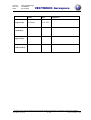
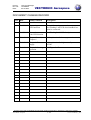
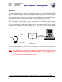
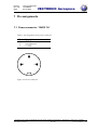
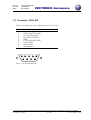
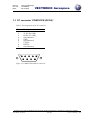
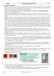
VECTRONIC Aerospace GmbH
Carl-Scheele-Str. 12
D-12489 Berlin
Germany
Telephone: +49 30 6789 4990
Telefax: +49 30 6789 5230
www.vectronic-aerospace.com
[email protected]
Project:
LM1 Link Manager
Title:
User Manual
Document No.: LM-UM005
Version: 1.4
Last Change: 22.01.2003
Project:
Doc. No.:
Date:
LM1 Link Manager
LM-UM005
22.01.2003
Prepared by
VECTRONIC Aerospace
Name
Date
Signature
R. Schulte
22.01.2003
Checked by
Approved by
Authorised by
This design is the property of VECTRONIC Aerospace GmbH. Unauthorised duplication or distribution to a third party is prohibited.
VECTRONIC Aerospace
2 /22
LM1 User Manual_1_4.doc
Project:
Doc. No.:
Date:
LM1 Link Manager
LM-UM005
22.01.2003
VECTRONIC Aerospace
DOCUMENT CHANGE RECORD
Issue Date
Item(s) Affected
Description
0
22.01.2003
Initial Issue
1
20.03.2002 Formatting
LED functions
General formatting corrected
Red Flashing Link LED when handheld terminal is connected
2
10.05.2002 Cover sheet,
Link LED function
Red Flashing Link LED description corrected
3
25.06.2002 Chapter General,
Chapter 6
Add explanation for battery protection circuit
4
22.01.2003 Chapter 1. Power
Supply
Add explanation for higher standby current
of LM1
22.01.2003 Chapter 2. Starting
operation
Add Figure 2 - 7
This design is the property of VECTRONIC Aerospace GmbH. Unauthorised duplication or distribution to a third party is prohibited.
VECTRONIC Aerospace
3 /22
LM1 User Manual_1_4.doc
Project:
Doc. No.:
Date:
LM1 Link Manager
LM-UM005
22.01.2003
VECTRONIC Aerospace
Table of Contents
General ......................................................................................................................................7
1 Power supply ......................................................................................................................8
2 Starting operation ..............................................................................................................9
3 Interfaces ..........................................................................................................................11
4 LED functions ..................................................................................................................12
4.1 Status of Link LED during SCI data transfer between collar / handheld terminal and
PC / Laptop............................................................................................................................12
4.2 Status of Link LED during reprogramming new firmware via SCI link ......................13
4.3 Status of Link LED during USB data transfer between collar and PC / Laptop ..........13
4.4 Status of Link LED during reprogramming new firmware via USB link ....................13
5 Charging the LM1 ...........................................................................................................14
6 Battery Protection System of the Link Manager LM1.................................................15
7 Pin assignments ................................................................................................................16
7.1 Power connector ‘12VDC 1A’ .....................................................................................16
7.2 Connector ‘COLLAR’ ..................................................................................................17
7.3 PC connector ‘COMPUTER (RS232)’.........................................................................18
8 Technical specifications...................................................................................................19
This design is the property of VECTRONIC Aerospace GmbH. Unauthorised duplication or distribution to a third party is prohibited.
VECTRONIC Aerospace
4 /22
LM1 User Manual_1_4.doc
Project:
Doc. No.:
Date:
LM1 Link Manager
LM-UM005
22.01.2003
VECTRONIC Aerospace
List of figures
Figure 1: Block diagram for the connection of the Link Manager with the GPS-Plus Collar and the PC ............. 7
Figure 2: Connector of the external power supply.................................................................................................. 9
Figure 3: Connection between PC/Laptop and LM1 with a RS232 cable............................................................... 9
Figure 4: Connection between PC/Laptop and LM1 with an USB cable.............................................................. 10
Figure 5: Connection between Collar and LM1 with the special link cable ......................................................... 10
Figure 6: RS232 connection (left) and USB connection (right) between Collar and PC/Laptop via LM1 ........... 10
Figure 7: RS232 and USB connection between Collar and PC/Laptop via LM1.................................................. 10
Figure 8: Front view of the Link Manager with all connectors and LED’s .......................................................... 11
Figure 9: LM1 turned upside down to reset the battery protection circuit ........................................................... 15
Figure 10: Power connector ................................................................................................................................. 16
Figure 11: COLLAR connector ............................................................................................................................. 17
Figure 12: COMPUTER (RS232) connector......................................................................................................... 18
This design is the property of VECTRONIC Aerospace GmbH. Unauthorised duplication or distribution to a third party is prohibited.
VECTRONIC Aerospace
5 /22
LM1 User Manual_1_4.doc
Project:
Doc. No.:
Date:
LM1 Link Manager
LM-UM005
22.01.2003
VECTRONIC Aerospace
List of Tables
Table 1: Charge LED function of the Link Manager............................................................................................. 12
Table 2: Link LED function of the Link Manager ................................................................................................. 12
Table 3: Pin assignment of the power connector .................................................................................................. 16
Table 4: Pin assignment of the COLLAR connector (3.3V level) .......................................................................... 17
Table 5: Pin assignment of the PC connector ....................................................................................................... 18
This design is the property of VECTRONIC Aerospace GmbH. Unauthorised duplication or distribution to a third party is prohibited.
VECTRONIC Aerospace
6 /22
LM1 User Manual_1_4.doc
Project:
Doc. No.:
Date:
LM1 Link Manager
LM-UM005
22.01.2003
VECTRONIC Aerospace
General
The Link Manager LM1 provides the interface between your PC or Laptop and the GPS-Plus
collar or a handheld terminal. It is used to exchange data and to upgrade new firmware in your
GPS-Plus collar or handheld terminal. With its own power, provided by an internal LithiumIon rechargeable battery, it can be used very easy to access the collar by an external PC and to
supply the collar with external power in case of an empty battery pack of the collar.
The Link Manager is quite simple to operate. Just connect it to a GPS-Plus collar or a handheld terminal and to the PC (as shown in Figure 1). Then run the PC software and the LED’s
give you information about the state of charge and the data transfer mode. Using the internal
accumulator as an autonomous power supply you are very flexible in use even in outdoor
operation.
Data link
GPS-Plus
Collar
Battery
Pack
Optional
power supply
Link
Manager
COM or USB
External Power
(optional)
Figure 1: Block diagram for the connection of the Link Manager with the GPS-Plus Collar and the PC
Note:
The Link Manager contains a tilt switch to reset the battery protection circuit and
to disconnect the internal battery from the electronics in case of malfunction (see
chapter 6 Battery Protection System of the Link Manager LM1). The Link Manager will not work in the upside down position!
This design is the property of VECTRONIC Aerospace GmbH. Unauthorised duplication or distribution to a third party is prohibited.
VECTRONIC Aerospace
7 /22
LM1 User Manual_1_4.doc
Project:
Doc. No.:
Date:
1
LM1 Link Manager
LM-UM005
22.01.2003
VECTRONIC Aerospace
Power supply
The Link Manager has an internal Li-Ion accumulator as an autonomous power supply. The
Link Manager changes from standby to operation mode automatically when receiving commands from the PC. During standby the accumulator has a life cycle of about nine months.
During operation the Link Manager can also be supplied with power by an external power
adapter that transforms an AC input voltage between 100 VAC and 250 VAC to a voltage of
12 VDC. During standby and operation mode the connected AC/DC power adapter will also
charge the internal Li-Ion accumulator of the Link Manager automatically.
Warning:
The standby current is much higher when the RS-232 cable is connected to a
PC (8 mA instead of 50 µA)! This will reduce the lifetime during standby from
several months to only several days with a full charged accumulator. To avoid
faster discharge of the accumulator, please disconnect the RS-232 cable from
the PC if the Link Manager is not in use, or connect the AC/DC power adapter
to the Link Manager. The higher standby current is only present when the PC
is switched off and the RS232 cable is connected to the PC. The higher
standby current is not present when the PC is only connected to the USB interface.
This design is the property of VECTRONIC Aerospace GmbH. Unauthorised duplication or distribution to a third party is prohibited.
VECTRONIC Aerospace
8 /22
LM1 User Manual_1_4.doc
Project:
Doc. No.:
Date:
LM1 Link Manager
LM-UM005
22.01.2003
VECTRONIC Aerospace
2 Starting operation
To exchange data between the GPS-Plus collar or the handheld terminal and the PC or Laptop
the Link Manager has to be used as an interface. To start operating the Link Manager, just
follow the steps 1 to 4:
1.
Connect the AC/DC power adapter to the Link Manager for external power supply (only
necessary if internal accumulator is low of charge) (Figure 2).
2.
Connect the Link Manager to the PC with a standard RS-232 cable between the RS-232
connector of the Link manager and one of the PC’s COM ports (Figure 3) or using a
USB cable between the USB connector of the Link Manager and a PC’s
USB port (Figure 4). Note: The USB connection will not work with a handheld terminal (see handheld terminal user manual).
3.
Connect the GPS-Plus collar or the handheld terminal with the special link cable to the
Collar interface connector of the Link Manager (Figure 5 - Figure 7).
4.
Start the GPS_PLUS.EXE software on the connected PC to upload or download data or
to reprogram new firmware.
Figure 2: Connector of the external power supply
Figure 3: Connection between PC/Laptop and LM1 with a RS232 cable
This design is the property of VECTRONIC Aerospace GmbH. Unauthorised duplication or distribution to a third party is prohibited.
VECTRONIC Aerospace
9 /22
LM1 User Manual_1_4.doc
Project:
Doc. No.:
Date:
LM1 Link Manager
LM-UM005
22.01.2003
VECTRONIC Aerospace
Figure 4: Connection between PC/Laptop and LM1 with an USB cable
Figure 5: Connection between Collar and LM1 with the special link cable
Figure 6: RS232 connection (left) and USB connection (right) between Collar and PC/Laptop via
LM1
Figure 7: RS232 and USB connection between Collar and PC/Laptop via LM1
This design is the property of VECTRONIC Aerospace GmbH. Unauthorised duplication or distribution to a third party is prohibited.
VECTRONIC Aerospace
10 /22
LM1 User Manual_1_4.doc
Project:
Doc. No.:
Date:
LM1 Link Manager
LM-UM005
22.01.2003
VECTRONIC Aerospace
3 Interfaces
The Link Manager has three connectors for interfacing the PC to a GPS-Plus collar or a handheld terminal. One connector is to plug in a special interface cable for the collar or terminal.
This connector then provides a data link between the Link Manager and the collar or terminal
as well as an optional power link to supply the collar externally when no battery pack is connected to the collar.
To establish a data link to the PC there are two ports available. The user can choose either the
RS-232 port of the Link Manager ‘COMPUTER (RS232)’ to be connected to a COM port of
the PC or the USB port ‘COMPUTER (USB)’ to be connected to a PC’s USB port via an adequate USB cable. With each port all data transfer functions can be performed with a collar. A
handheld terminal can only be connected via the Link Manager, if the RS-232 PC connection
is used (see handheld terminal user manual).
Finally there is an external power input for an optional electrical power supply of the device.
An auxiliary AC/DC power adapter delivers a 12 VDC supply voltage. This additional power
is required to recharge the internal accumulator in case of a low voltage (red flashing
LED ‘LINK’). Figure 8 shows the front view of the Link Manager with all connectors and
LED’s:
LED for
Charge
Control
External
Power
Input
Interface to
GPS-Plus
collar
LED for
Link Control
Interface to
PC COM Port
Interface to
PC USB Port
Figure 8: Front view of the Link Manager with all connectors and LED’s
This design is the property of VECTRONIC Aerospace GmbH. Unauthorised duplication or distribution to a third party is prohibited.
VECTRONIC Aerospace
11 /22
LM1 User Manual_1_4.doc
Project:
Doc. No.:
Date:
LM1 Link Manager
LM-UM005
22.01.2003
VECTRONIC Aerospace
4 LED functions
There are two LED’s on the front panel of the Link Manager indicating the state of accumulator charge and the operation modes. Each LED can emit three colours – red, green or yellow,
whereas the ‘Charge’ LED can only be active when an external power supply is connected to
the Link Manager.
The meaning of each colour is summarised in Table 1 and Table 2.
Table 1: Charge LED function of the Link Manager
LED CHARGE Function
(Only in use with Yellow
external power) Green
Red
Off
State
Fast charge (0...80%)
Full charge (80...100%)
Malfunction
Accumulator full charged
Table 2: Link LED function of the Link Manager
LED LINK
(Always in use)
Function
Green flashing
State
Stand-by, accumulator voltage ok.
Red flashing
Stand-by:
-
If Handheld terminal is connected, same as green
flashing
-
If not connected: Low accumulator voltage (ca. 20%
capacity left, accumulator should be recharged)
Green
USB control
Yellow
Only used before programming via serial interface
Red
Programming new firmware via serial or USB interface
4.1 Status of Link LED during SCI data transfer between collar / handheld terminal and PC / Laptop
The Link LED is flashing red or green with a period of 3 to 4 seconds in standby mode. When
the Link LED is flashing green, the voltage of the internal Li-Ion accumulator is within the
operating range. If the Link LED is flashing red and the handheld terminal is not connected,
the voltage of the Li-Ion accumulator is low and the accumulator should be recharged as soon
as possible with the external AC/DC power adapter. If the handheld terminal is connected,
the Link LED can flashing red nevertheless the accumulator is charged.
This design is the property of VECTRONIC Aerospace GmbH. Unauthorised duplication or distribution to a third party is prohibited.
VECTRONIC Aerospace
12 /22
LM1 User Manual_1_4.doc
Project:
Doc. No.:
Date:
LM1 Link Manager
LM-UM005
22.01.2003
VECTRONIC Aerospace
4.2 Status of Link LED during reprogramming new firmware via SCI
link
The Link LED is first switch on yellow for some seconds. This indicates that the internal
processor of the Link Manager is waked up. After that the PC program starts immediately
with programming new firmware. During programming the Link LED is switched on red with
short bursts of yellow. At the end of the programming cycle the Link Manager will enter the
standby mode automatically.
4.3 Status of Link LED during USB data transfer between collar and
PC / Laptop
As soon as the PC / Laptop exchanges data with the collar via the USB interface, the
Link LED is switched on green. When the Link Manager was in standby mode, it takes a moment until the Link Manager is waked up. Some seconds after the last communication via the
USB interface, the Link Manager LM1 will enter the standby mode automatically.
4.4 Status of Link LED during reprogramming new firmware via
USB link
The Link LED is first switched on green. This indicates that the USB connection is established. Directly after that the PC program starts with programming new firmware. During
programming new firmware, the Link LED is switched on red with short bursts of green. At
the end of the programming cycle the Link Manager will enter the standby mode automatically.
Note:
When the Link LED is completely switched off, neither flashing red nor green nor
switched on red, green or yellow, the internal Li-Ion accumulator is absolutely discharged and should be recharged with the external AC/DC power adapter immediately.
This design is the property of VECTRONIC Aerospace GmbH. Unauthorised duplication or distribution to a third party is prohibited.
VECTRONIC Aerospace
13 /22
LM1 User Manual_1_4.doc
Project:
Doc. No.:
Date:
LM1 Link Manager
LM-UM005
22.01.2003
VECTRONIC Aerospace
5 Charging the LM1
The Link Manager LM1 includes a state machine that controls the charging algorithm for the
Li-Ion accumulator. When power is applied the state machine goes into the reset state where
the timers are reset to zero to prepare for charging. From the reset state, it enters the prequalification state. In this state, 1/10 of the fast-charge current charges the accumulator, and the
accumulator voltage is measured. If the voltage is above the under voltage threshold it will
enter the fast-charge state. If the accumulator voltage does not rise above the under voltage
threshold before the prequalification timer expires (15 minutes), the charging terminates and
the Charge LED is switched red.
In the fast-charge state, the Charge LED is switched yellow and the accumulator charges with
a constant current of about 1A. If the accumulator voltage reaches the voltage limit before the
fast timer expires (3 hours) the LM1 enters the full-charge state. If the fast-charge timer expires before the voltage limit is reached, charging terminates and the Charge LED is switched
red. In the full-charge state, the Charge LED is switched green and the accumulator charges at
a constant voltage. When the charging current drops below 100mA, or if the full-charge timer
expires (3 hours), the state machine enters the top-off state. In the top-off state, the accumulator continues to be charged at a constant voltage until the top-off timer expires (90 minutes)
when it enters the done state. In the done state, charging stops and the Charge LED is
switched off until the battery voltage drops below the recharge voltage threshold when it enters the reset state to start the charging process again.
Warning:
Do not charge the Li-Ion accumulator below 0°C or above 50°C. Charging the
Li-Ion accumulator outside the charging temperature range (0°C to +50°C)
will destroy your Link Manager.
This design is the property of VECTRONIC Aerospace GmbH. Unauthorised duplication or distribution to a third party is prohibited.
VECTRONIC Aerospace
14 /22
LM1 User Manual_1_4.doc
Project:
Doc. No.:
Date:
LM1 Link Manager
LM-UM005
22.01.2003
VECTRONIC Aerospace
6 Battery Protection System of the Link Manager LM1
The internal Li-Ion accumulator is protected against over current and deep discharge. Under
special conditions (to high current consumption or electrostatic discharge) the battery protection circuit will disconnect the Li-Ion accumulator from the remaining electronics to avoid
damaging of the Li-Ion accumulator. The accumulator will be activated again when you removed all interface cables and plug in the external power adapter or when you turn the LM1
upside down for at least one second (as shown in Figure 9). The Link Manager has an internal
tilt switch to disconnect the Li-Ion accumulator from the electronics. When you turn the Link
Manager upside down, the tilt switch will disconnect the accumulator from the electronics and
will reset the battery protection circuit. After the LM1 is turned back, the battery is connected
again to the electronics.
.
Figure 9: LM1 turned upside down to reset the battery protection circuit
This design is the property of VECTRONIC Aerospace GmbH. Unauthorised duplication or distribution to a third party is prohibited.
VECTRONIC Aerospace
15 /22
LM1 User Manual_1_4.doc
Project:
Doc. No.:
Date:
LM1 Link Manager
LM-UM005
22.01.2003
VECTRONIC Aerospace
7 Pin assignments
7.1 Power connector ‘12VDC 1A’
Table 3: Pin assignment of the power connector
Pin
1
2
3
Description
GND
not connected
12 VDC
2
3
1
Figure 10: Power connector
This design is the property of VECTRONIC Aerospace GmbH. Unauthorised duplication or distribution to a third party is prohibited.
VECTRONIC Aerospace
16 /22
LM1 User Manual_1_4.doc
Project:
Doc. No.:
Date:
LM1 Link Manager
LM-UM005
22.01.2003
VECTRONIC Aerospace
7.2 Connector ‘COLLAR’
Table 4: Pin assignment of the COLLAR connector (3.3V level)
Pin
1
2
3
4
5
6
7
8
9
Description
Vcc Collar (3.3 – 3.6 V)
RTS Collar (CTS LM1)
Tx Collar (Rx LM1)
Rx Collar (Tx LM1)
GND
CTS Collar (RTS LM1)
Clock Collar
Reset Collar
not connected
1
5
6
9
Figure 11: COLLAR connector
This design is the property of VECTRONIC Aerospace GmbH. Unauthorised duplication or distribution to a third party is prohibited.
VECTRONIC Aerospace
17 /22
LM1 User Manual_1_4.doc
Project:
Doc. No.:
Date:
LM1 Link Manager
LM-UM005
22.01.2003
VECTRONIC Aerospace
7.3 PC connector ‘COMPUTER (RS232)’
Table 5: Pin assignment of the PC connector
Pin
1
2
3
4
5
6
7
8
9
Description
not connected
Tx PC (Rx LM1)
Rx PC (Tx LM1)
not connected
GND
not connected
CTS PC
RTS PC
not connected
5
1
9
6
Figure 12: COMPUTER (RS232) connector
This design is the property of VECTRONIC Aerospace GmbH. Unauthorised duplication or distribution to a third party is prohibited.
VECTRONIC Aerospace
18 /22
LM1 User Manual_1_4.doc
Project:
Doc. No.:
Date:
LM1 Link Manager
LM-UM005
22.01.2003
VECTRONIC Aerospace
8 Technical specifications
Mechanics
Dimensions:
105 x 76 x 44 mm
Weight:
350 g
Operating temperature:
0°C...+50°C (charging)
-20°C...+60°C (non charging)
Storage temperature:
-40°C...+80°C
Power
Supply voltage:
7...20 VDC via external AC/DC power adapter or via internal 2.3
Ah Li-Ion accumulator.
Automatic standby function for power saving
Accumulator lifetime:
Up to 9 months in standby mode
Charging time:
< 4 hours
Interface
PC:
RS232 or USB port
Collar,
Handheld Terminal:
Special serial link cable
This design is the property of VECTRONIC Aerospace GmbH. Unauthorised duplication or distribution to a third party is prohibited.
VECTRONIC Aerospace
19 /22
LM1 User Manual_1_4.doc
Project:
Doc. No.:
Date:
LM1 Link Manager
LM-UM005
22.01.2003
VECTRONIC Aerospace
Notes
This design is the property of VECTRONIC Aerospace GmbH. Unauthorised duplication or distribution to a third party is prohibited.
VECTRONIC Aerospace
20 /22
LM1 User Manual_1_4.doc
Project:
Doc. No.:
Date:
LM1 Link Manager
LM-UM005
22.01.2003
VECTRONIC Aerospace
Notes
This design is the property of VECTRONIC Aerospace GmbH. Unauthorised duplication or distribution to a third party is prohibited.
VECTRONIC Aerospace
21 /22
LM1 User Manual_1_4.doc
Project:
Doc. No.:
Date:
LM1 Link Manager
LM-UM005
22.01.2003
VECTRONIC Aerospace
Notes
This design is the property of VECTRONIC Aerospace GmbH. Unauthorised duplication or distribution to a third party is prohibited.
VECTRONIC Aerospace
22 /22
LM1 User Manual_1_4.doc