1
User Manual
SPD3000 Series
Programmable DC Power Supply
2012 SIGLENT TECHNOLOGIES CO., LTD
SIGLENT
Copyright information
1.
SIGLENT TECHNOLOGIES CO., LTD. All Rights Reserved.
2.
Information in this publication replaces all previous corresponding material.
3.
SIGLENT reserves the right to change the specifications and price of the
product.
4.
Any way of copying, extracting and translating the content of the manual is
not allowed without permission of SIGLENT.
Note:
SIGLENT is the registered trademark of SIGLENT TECHNOLOGIES CO., LTD.
SPD3000 User Manual
I
SIGLENT
General Safety Summary
Please review the following safety precautions carefully to avoid personal injury
or damage to this product or any product connected to it. To prevent potential
danger, please use the instrument as specified.
Use proper power cord
Only the power cord designed for the instrument and authorized by local country
could be used.
Power supply
AC Input Voltages: 100V/120V/220V/230V ±10%, 50/60Hz.
Use proper fuse
The fuse types: 100V/120V: T6.3A/250V; 220V/230V: T3.15A/250V;
Make sure to use the correct type of fuse before turning on the instrument.
Do not connect the power cord before replacing the fuse.
Find out the reason why the fuse burned out before replacing the fuse.
Ground the instrument
The instrument is grounded through the protective terra conductor of the power
cord. To avoid electric shock, the grounding conductor must be connected to
the earth. Make sure that the instrument is properly grounded before any inputs
or outputs.
Observe all terminal ratings
To avoid fire or electric shock, please observe all ratings and symbols on the
instrument. Read this guide carefully to know more details about the ratings
before connection.
Keep proper ventilation
Inadequate ventilation may cause an increase of temperature,, which will lead
to further damage. Please keep proper ventilation and check the fan and air-vents
regularly when using the instrument.
Operate condition
Location: indoor, no strong light, almost no Interfering pollution;
Comparative humidity: <80%
Altitude: <2000m
Temperature: 0℃ to 40℃
II SPD3000 User Manual
SIGLENT
Do not operate in an explosive atmosphere
To avoid personal injury or damage to instrument, please do not operate in an
explosive atmosphere.
Keep surface of the product clean and dry
To avoid dust or moisture in the air influence the performance of the instrument,
please keep surface of the product clean and dry.
SPD3000 User Manual
III
SIGLENT
Safety Terms and Symbols
Terms may appear on the product:
DANGER: Indicates direct injury or hazard that may happen.
WARNING: Indicates potential injury or hazard that may happen.
CAUTION: Indicates potential damage to the instrument or other property that
may happen.
Symbols may appear on the product:
Hazardous
Protective
Voltage
Earth Ground
IV SPD3000 User Manual
Warning
Earth
Power
Ground
Switch
SIGLENT
SPD3000 Series Brief Introduction
SPD3000 series Programmable DC Power Supply is convenient, flexible and
multi-function. It has three independent outputs, two sets of adjustable voltage
value and a fixed set of selectable voltage value of 2.5V, 3.3V, and 5V,and it
also provides output short circuit and overload protection at the same time.
Main features of SPD3000 Series
4.3” TFT color LCD display with content of 16M;
Three independent outputs, two of which are adjustable, and the total power up
to 195W;
Four kinds of input voltage values includes 100V, 120V, 220V and 230V
to satisfy different requirements;
Function of storage and call setting parameters;
Function of timing output;
Function of waveform display, Real-time display of voltage or current waveforms
with digital display of voltage, current and power values;
Start up screen protective procedure every fixed interval (30 minutes);
Perfect PC software to realize the real-time control through USBTMC.
SPD3000 User Manual
V
SIGLENT
Content
General Safety Summary.................................................................................................... II
SPD3000 Series Brief Introduction..................................................................................... V
Chapter 1 Start Guide .......................................................................................................... 1
The front panel ..........................................................................................................................2
The rear panel ...........................................................................................................................6
Notice in first use of SPD3000 Series .................................................................................7
Input power requirement ...........................................................................................................7
Electrical check .........................................................................................................................7
Output check .............................................................................................................................8
Chapter 2 Control panel operation ...................................................................................... 9
2.1 Output summary ............................................................................................................10
2.2 CH1/CH2 Independent Output..................................................................................... 11
2.3 CH3 Independent mode................................................................................................12
2.4 CH1/CH2 Series mode .................................................................................................13
2.5 CH1/CH2 Parallel mode ...............................................................................................15
2.7 Timer ................................................................................................................................17
2.9 Version information........................................................................................................20
2.10 Upgrade firmware ........................................................................................................21
Chapter 3 Remote control ................................................................................................. 23
3.1 Command list..................................................................................................................23
3.2 Command description ...................................................................................................24
Chapter 4 Specification...................................................................................................... 30
Chapter 5 Troubleshooting ................................................................................................ 32
Chapter 6 Service and Support .........................................................................................33
Maintain summary ................................................................................................................33
Contact SIGLENT.................................................................................................................33
Appendix A: Accessories ........................................................................................................34
VI SPD3000 User Manual
SIGLENT
Chapter 1 Start Guide
In this chapter, we mainly introduce the panel and Display Interface of SPD3000,
and also the notes about how to check and operate it at the first use. You can
quickly understand how to operate it after reading the following steps.
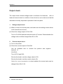
Please check the instrument according to the following steps.
1. The machine and packing inspection
If the packing or cushioning material is seriously damaged, please retained them
for follow-up inspection.
If the instrument is damaged during shipment, the compensation will be provided
by consigner or carrier, and SIGLENT will not undertake free repair or
replacement.
If there is a mechanical damage or loss please contact with your sales
representative.
2. Accessory examination
Information about the accessories is introduced in detail at the end of the manual,
you can refer to this description to check whether the accessories are
completed.
If there are accessories damaged or lacked, please contact with your
SIGLENT sales representative.
SPD3000 User Manual
1
SIGLENT
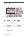
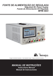
The front panel
1
○
2
○
3
○
4
○
5
○
6○
7○
8○
9○
10
○
11
○
12
○
13
○
14
○
15
○
NO.
Description
NO.
Description
1
Logo
9
CH3 DIP Switch
2
Display Area
10
Power Switch
3
Model
11
CH1 Output Terminal
4
System parameter
configuration button
12
Ground Terminal
5
Multi-function knob
13
CH2 Output Terminal
6
Fine Adjust button
14
CV/CC indicator light
7
Right/Left Direction button
15
CH3 Output Terminal
8
Channel Control button
2 SPD3000 User Manual
SIGLENT
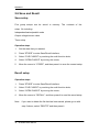
Instruction for buttons
Buttons for setting parameters
WAVEDISP
SER
: Press the button to turn on/off the waveform display interface;
: Press the button to set series mode of CH1/CH2, and the logo
“
PARA
” displays at the same time;
:Press the button to set parallel mode of CH1/CH2, and the logo
“
” displays at the same time;
RECALL/SAVE
:Press the button to enter the storage function interface
:Press the button to enter timer setting interface
TIMER
LOCK/VER
: Press the button longer to lock it and shorter to turn to system
information interface.
Buttons for controlling the channel
ALL ON/OFF
: Press the button to turn on/off all the channels;
CH1
: Press the button to select CH1 as the current channel;
CH2
: Press the button to select CH2 as the current channel;
: Press the button to turn on/off the CH1 output;
ON/OFF
CH3 ON/OFF
: Press the button to turn on/off the CH3 output.
Other buttons
FINE
: Press the button to open the fine tuning function and change the
parameters with the minimum step;
: To move the cursor around.
SPD3000 User Manual
3
SIGLENT
The output terminal on front panel
The output terminals of CH1、CH2 and CH3 include positive terminal
and
negative terminal, and a common ground for CH1 and CH2 additional. Each
channel
has
introduced
in
its
own
logo.
The
operation
the follow-up ” control panel operation”.
4 SPD3000 User Manual
details
are
SIGLENT
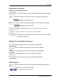
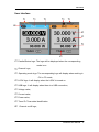
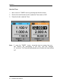
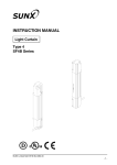
User interface
1
○
2
○
3
○
4
○
5
○
10
○
6○
7○
8
○
9○
1
○
Parallel/Series logo: The logo will be displayed when the corresponding
mode is on
2
○
Channel logo;
3
○
Operating mode logo: The corresponding logo will display when working in
CV or CC mode;
4○ LOCK logo: It will display when the LOCK is turned on
5○ USB logo: It will display when there is a USB connection;
6
○
Voltage value;
7○ Current value;
8
○
Power value;
9○ Timer lD: Timer state identification
10
○
Channel on/off logo;
SPD3000 User Manual
5
SIGLENT
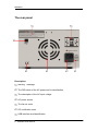
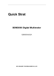
The rear panel
1○
2○
7
○
6○
5○
Description:
1
○
warning message
2
○
The DIP switch of the AC power and its identification .
3
○
The description of the AC input voltage
4
○
AC power socket
5
○
The fan air vents
6○ CE certification mark
7○ USB interface and identification
6 SPD3000 User Manual
4○
3○
SIGLENT
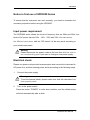
Notice in first use of SPD3000 Series
To ensure that the instrument can work normally,, you need to undertake the
necessary inspection before using the SPD3000.
Input power requirement
The SPD3000 series allows two kinds of frequency that are 50hz and 60hz, four
kinds of AC power that are 100v、120v、220v and 230v. You can choose
the different input power with the “DIP switch ”at the rear panel according to
your actual requirement.
Warning
Pease disconnect the power cords at first and then dial the code to
the corresponding gear if you want to change a new power supply.
Electrical check
Please use power cord provided as accessories and connect the instrument to
AC power first, and then starting power check according to the following steps.
1.
Connect the power supply
Warning
To avoid electrical shock, please make sure that the instrument has
been properly earth.
2.
Turn on the power switch
Press the button “POWER” to enter boot interface, and the default setup
will show automatically after a while.
SPD3000 User Manual
7
SIGLENT
Output check
The output check includes voltage check in condition of all channels
with no
load and current check in condition of short circuit so as to make sure that the
instrument correctly responds to operation of the front panel.
1.
Voltage output check
(1) Within no load, turn on the power, and make sure the setting current values
of all channels are not zero;
(2) Check the voltage output of CH1/CH2
Turn on CH1/CH2 and the instrument work in CV mode. Check whether the
voltage value could be changed from 0V to 32V.
2.
Current output check
(1) Turn on the power.
(2) Check the current output of CH1/CH2
Use an insulated wire to connect the positive and negative
terminal of
CH1/CH2;
Turn off CH1 and CH2;
Revolve the knob to set the voltage value to 32V;
Revolve the knob to set the current value to 0A;
Adjust the current parameters to check whether the current value can be
changed from 0A to 3.2A.
8 SPD3000 User Manual
SIGLENT
Chapter 2 Control panel operation
In this chapter,the function and operation of SPD3000 series control panel will
be introduced in detail to giving you an all-around understanding of it, which
will eventually lead to easier work.
Brief introduction:
Output summary
CH1/CH2 independent output
CH3 independent output
Parallel output
Series output
Waveform display
Timer
Save and recall
SPD3000 User Manual
9
SIGLENT
2.1 Output summary
Summary
SPD3000 series have three independent outputs, two of which are adjustable
in voltage value and the other one includes selectable 2.5V, 3.3V or 5.0V
Independent/Parallel/Series
SPD3000 series have three output modes: independent、parallel and series,
which
can
panel.
In
be
selected
through
the
track
switch
on
the
front
the independent mode, the output current and voltage are
controlled respectively.
In the parallel mode, the current value is
twice that of the single channel. In
the series mode, the voltage value is twice that of the single channel.
Constant voltage/current
In the constant current mode (independent or tracking mode), the current value
is rated and controlled through the front panel. The indicator light displays red
and the voltage value is under rating. It will return to constant voltage mode
when the current value is under dating.
In the constant voltage mode, the current value is less than the setting value,
and the voltage value is controlled through the front panel. The indicator light
displays
green
and
the
current
value
is
maintained
at
the
set
value. It will return to constant current mode when the voltage value is under
dating.
10
SPD3000 User Manual
SIGLENT
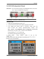
2.2 CH1/CH2 Independent Output
Instruction CH1 and CH2 are working in the independent mode, at the same
time,they are insulated from the ground.
Output rating
0~30V/0~3A
(max:32V, 3.2A)
Operation steps
1.
Make sure that parallel/series mode is off.
2.
Connect load to the positive and negative terminals of CH1/CH2.
3.
Set voltage and
cursor
to select
then
revolve
current value of CH1/CH2: Firstly, move
the
wanted
parameter(voltage , current),
the
and
the multi-function knob to change the corresponding
parameter(you can press “FINE” to make accurate adjusting).
Coarse adjusting: 0.1V or 0.1A each step.
Fine adjusting: the least precision each step.
4. Open output : Press “ON/OFF” button to turn on the
output, the
corresponding indicator light gets lighted immediately and “CC” or “CV” is
showed on the current interface.
SPD3000 User Manual
11
SIGLENT
2.3 CH3 Independent mode
Instruction
CH3 is independent from CH1 and CH2, and it works neither in parallel mode
nor in series mode. Its voltage and current ratings are respectively 2.5V,3.3V,
5V and 3A.
Output ratings
2.5V/3.3V/5V, 3A
Operation steps:
1.
Connect the load to the positive and negative terminals of CH3 on the front
panel.
2.
Select the wanted voltage value by moving CH3 “DIP switch”.
3.
Open
output,
CV
output
: Press
“ON/OFF”
button
to
turn
on
the
the corresponding indicator light gets lighted immediately.
CC
When the current value is higher than 3A, the overload indicator light turns red
and the working mode turns to CC from CV
Note: “overload” does not mean abnormal operation.
12
SPD3000 User Manual
SIGLENT
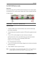
2.4 CH1/CH2 Series mode
Instruction
In the series mode, CH1 and CH2 are linked internally into one channel which
is controlled by CH1, and the output voltage value is twice compared with that
of single channel.
Output rating
0~60V/0~3A
(max: 64V,3.2A)
Operation steps:
1.
Press the “SER” button to start the Series mode, and the indicator light
turns bright immediately;
2.
Connect the load to the positive terminal of CH2 and the negative terminal
of CH1;
3.
Turn on CH2, and then adjust its current value by revolving the
multi-function button to 3A. In the default setup, the instrument works in
“Coarse”, you can turn to “Fine” by pressing “FINE” button;
Coarse: 0.1V or 0.1A each step;
Fine: the least precision each step;
4.
Turn on CH1, and then set the output voltage/current value by revolving the
multi-function knob;
5.
Press “ON/OFF” button to open the output.
Note: You can identify the current working state “CC” or ”CV” by referring to
indicator light of CH1/CH2.(red means CV, green means CC).
SPD3000 User Manual
13
SIGLENT
14
SPD3000 User Manual
SIGLENT
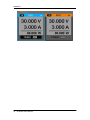
2.5 CH1/CH2 Parallel mode
Instruction In the parallel mode, CH1 and CH2 are linked internally into one
channel which is controlled by CH1. Its output current value is
twice as much as the single channel.
Output rating
0~30V/0~6A
Operation steps:
Press the “PAR” button to start Parallel mode, and the indicator light turns
bright immediately;
2. Connect the load to the positive and negative terminal of CH1;
3. Turn on CH1, and then set the output voltage/current value by revolving the
multi-function knob;
4. Press “ON/OFF” button to open the output.
1.
Note: You can identity the current working state “CC” or ”CV” by
referring to indicator light of CH1/CH2.(red means CV, green means
CC);
In parallel mode, CH2 only works in CC mode.
SPD3000 User Manual
15
SIGLENT
2.6 Save and Recall
Save setup
Five group setups can be saved in memory. The contents of the
setup file including:
Independent/series/parallel mode
Output voltage/current value
Timer setup
Operation steps
1.
Set the state that you wanted;
2.
Press “STORE” to enter Save/Recall interface;
3.
Select “FILE CHOICE” by revolving the multi-function knob;
4.
Select “OPEN CHOICE” by moving the cursor;
5.
Move the cursor to “STORE”, and then press it to save the current setup.
Recall setup
Operation steps:
1.
Press “STORE” to enter Save/Recall interface;
2.
Select “FILE CHOICE” by revolving the multi-function knob;
3.
Select “OPEN CHOICE” by moving the cursor;
4.
Move the cursor to “RECALL”, and then press it to read the saved setup.
Note: if you want to delete the file that has been saved, please go on with
step 3 above, select “DELETE” and then press it.
16
SPD3000 User Manual
SIGLENT
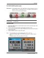
2.7 Timer
The timer works in the Independent mode, and can save five timing setups,
each of which is independent from each other. You can set any voltage/current
value within the range as you want. The timer supports consecutive
output, and the longest time of each group is 10000s.
Setup steps:
1.
Press CH1/CH2 to select the wanted channel;
2.
Press “TIMER” to enter the Timer Setup interface, and the indicator light
turns bright immediately;
3. Move the cursor to select the wanted parameter(voltage/current/time)
by
pressing the direction button;
4.
Revolve the multi-function knob to set the corresponding value and then
press it.
5.
Press “Timer” again to exit current interface.
SPD3000 User Manual
17
SIGLENT
Start the Timer
1.
Move cursor to “TIMER” menu by pressing the direction button;
2.
Revolve the multi-function knob to make the Timer state to “ON”;
3.
Press the knob to start the Timer.
Note: If press the “TIMER” button when the timer is running, then you
can observe the decreasing of the time ,and the changes
of the curve .The Timer will automatically turn off when the time reduces
to 0.
18
SPD3000 User Manual
SIGLENT
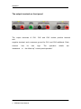
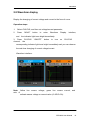
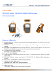
2.8 Waveform display
Display the changing of current voltage and current in the form of curve.
Operation steps:
1.
Select CH1/CH2, and then set voltage/current parameter;
2.
Press
and
“WAVE”
button
to
enter
Waveform
Display
interface,
the indicator light turns bright immediately.
3. Press CH1/CH2
channel, the
“ON/OFF”
button
to
turn
on
CH1/CH2
corresponding indicator light turns bright immediately and you can observe
the real-time changing of current voltage/current.
Waveform interface:
Note: Yellow line means voltage, green line means current, and
axis of
ordinate means voltage or current value (0~30V/0~3A).
SPD3000 User Manual
19
SIGLENT
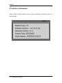
2.9 Version information
Press “LOCK” button quickly to enter Version Information interface, which is
shown below:
20
SPD3000 User Manual
SIGLENT
2.10 Upgrade firmware
The software of the instrument is upgraded with a fixed name file
via PC
management software with USBTMC. The upgrade method is below:
Upgrade in normal Interface
1.
Open the EasyPower software after USB line
connected perfectly, and make sure the instrument
with the software correctly.
having been
is connected
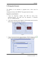
2.
Click Version and then choose Upgrade in the drop-down menu to enter the
USB firmware upgrade dialogue. See figure 1:
Figure 1
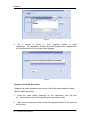
3.
Figure 2 shows the firmware upgrade dialogue. Click file choosing icon
and then select the file to be upgraded which must have a postfix ugf.
,
Figure 2
SPD3000 User Manual
21
SIGLENT
Figure 3
4.
As it shows in figure 4, click Upgrade button to start
upgrading. The upgrade is finished when the progress bar complete and
the instrument will run the version after upgrade.
Figure 4
Upgrade Via Guide Procedure
Upgrade via guide procedure also can be used if the method above is failed.
Specific steps are below:
1.
Press the knob before powering on the instrument, and the turn
on the instrument and it will enter the guide procedure mode.
2.
After enter the guide procedure mode, the upgrade method is the same as
the first one.
22
SPD3000 User Manual
SIGLENT
Chapter 3 Remote control
The SCPI Commands are used to perform remote control through USBTMC.
Connect the USB device on the rear panel
to computer which
has been
installed with EasyPower software or NI(Measurement & Automation).
3.1 Command list
1. *IDN?
2. *SAV
3. *RCL
4. INSTrument {CH1|CH2}
5. INSTrument ?
6. MEASure:CURRent?
7. MEAsure:VOLTage?
8. MEASure:POWEr?
9. [SOURce:]CURRent <current>
10. [SOURce:]CURRent ?
11. [SOURce:]VOLTage <volt>
12. [SOURce:] VOLTage?
13. OUTPut
14. OUTPut:TRACk
15. OUTPut:WAVE
16. TIMEr:SET
17. TIMEr:SET?
18. TIMEr
19. SYSTem:ERRor?
20. SYSTem:VERSion?
21. SYSTem: STATus?
SPD3000 User Manual
23
SIGLENT
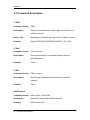
3.2 Command description
1.*IDN?
Command format
*IDN?
Description
Query the manufacturer, product type, series NO. and
software version.
Return Info
Manufacturer, product type, series NO., software version.
Example
Siglent, SPD3303S, SPD00001130025, 1.01.01.02.
2.*SAV
Command format
*SAV <name>
Description
Save current state in nonvolatile memory with the
specified name.
Example
*SAV 1
3.*RCL
Command format
*RCL <name>
Description
Recall state that had been saved from nonvolatile
memory.
Example
*RCL 1
4.INSTrument
Command format
INSTrument <CH1|CH2>
Description
Select the channel that will be operated.
Example
INSTrument CH1
24
SPD3000 User Manual
SIGLENT
Command format
INSTrument?
Description
Query the current operating channel
Example
INSTrument?
Return Info
CH1
5.MEASure
Command format
MEASure: CURRent? < CH1|CH2>
Description
Query current value for specified channel, if there is no
specified channel, query the current channel.
Example
MEASure: CURRent? CH1
Return Info
3.000
Command format
MEASure: VOLTage? < CH1|CH2>
Description
Query voltage value for specified channel, if there is no
specified channel, query the current channel.
Example
MEASure: VOLTage? CH1
Return Info
30.000
Command format
MEASure: POWEr? < CH1|CH2>
Description
Query power value for specified channel, if there is no
specified channel, query the current channel.
Example
MEASure: POWEr? CH1
Return Info
90.000
SPD3000 User Manual
25
SIGLENT
6.SOURce
Command format
<SOURce:>CURRent <value>
<SOURce>:={CH1 | CH2}
Description
Set current value of the selected channel
Example
CH1:CURRent 0.5
Command format
<SOURce>: CURRent?
<SOURce>:={CH1 | CH2}
Description
Query the current value of the selected channel.
Example
CH1: CURRent?
Return Info
0.500
Command format
<SOURce>: VOLTage <value>
<SOURce>:={CH1 | CH2}
Description
Set voltage value of the selected channel
Example
CH1: VOLTage 25
Command format
<SOURce>:CURRent?
<SOURce>:={CH1 | CH2}
Description
Query the voltage value of the selected channel.
Example
CH1: VOLTage?
Return Info
25.000
26
SPD3000 User Manual
SIGLENT
7.OUTPut
Command format
OUTPut <SOURce>, <state>
<SOURce>:={CH1 | CH2}; <state>:={ON | OFF}
Description
Turn on/off the specified channel.
Example
OUTPut CH1, ON
Command format
OUTPut: TRACK <NR1>
<NR1>:={0[Independent] | 1[Series] | 2[Parallel]}
Description
Select operation mode
Example
OUTPut: TRACK 0
Command format
OUTPut: WAVE<SOURce>, <state>
<SOURce>:={CH1 | CH2}; <state>:={ON | OFF}
Description
Turn on/off the Waveform Display function of specified
channel.
Example
OUTPut: WAVE CH1, ON
8.TIMEr
Command format
TIMEr: SET <SOURce>, <secnum>, <volt>, <curr>,
<time>
<SOURce>:={CH1 | CH2}; < secnum >;=1 to 5;
Description
Set timing parameters of specified channel
Example
TIMEr: SET CH1, 2, 3, 0.5, 2
SPD3000 User Manual
27
SIGLENT
Command format
TIMEr: SET? <SOURce>, <secnum>
<SOURce>:={CH1 | CH2}; < secnum >;=1 to 5;
Description
Query the voltage/current/time parameters of specified
group of specified channel.
Example
TIMEr: SET? CH1, 2
Return Info
3, 0.5, 2
Command format
TIMEr <SOURce>, <state>
<SOURce>:={CH1 | CH2}; < state >;={ON | OFF};
Description
Turn on/off Timer function of specified channel
Instruction
The command works effectivly only when <secnum>
starts from 1.
Example
TIMEr CH1, ON
9.SYSTem
Command format
SYSTem: ERRor?
Description
Query the error code and the information of the
equipment.
Command format
SYSTem: VERSion?
Description
Query the software version of the equipment.
Example
SYSTem: VERSion?
Return Info
1.01.01.02
28
SPD3000 User Manual
SIGLENT
Command format
SYSTem: STATus?
Description
Query the current working state of the equipment.
Instruction
The return info is Hexadecimal format, but the actual
state is binary , so you must change the return info into a
binary. The state correspondence relationship is as
follow.
Example
SYSTem: STATus?
Return info
0x0224
Bit NO.
Corresponding state
0
0: CH1 CV mode;
1: CH1 CC mode
1
0: CH2 CV mode;
1: CH2 CC mode
2,3
01: Independent mode;
10: Parallel mode
11: Series mode
4
0: CH1 OFF
1: CH1 ON
5
0: CH2 OFF
1: CH2 ON
6
0: TIMER1 OFF
1: TIMER1 ON
7
0: TIMER2 OFF
1: TIMER2 ON
8
0: CH1 digital display;
1: CH1 waveform diplay
9
0: CH2 digital display;
1: CH2 waveform diplay
SPD3000 User Manual
29
SIGLENT
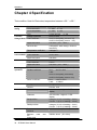
Chapter 4 Specification
Test condition: Heat for 30minutes, temperature between +20℃~+30℃.
Output
rating
Constant
Voltage Mode
0~30V , 0~3A
0~60V , 0~3A
0~30V , 0~6A
2.5V/3.3V/5.0V , 0~3A
≤0.01%+3mV
≤0.01%+3mV(rating current ≤ 3A)
≤0.02%+5mV(rating current >3A)
≤1mVrms(5Hz~1MHz)
CH1/CH2 independent
CH1/CH2 series
CH1/CH2 parallel
CH3
Voltage coefficient
Load coefficient
Ripple and noise
Recover time
Temperature coefficient
≤100μs(50% load change, minimum
load 0.5A)
≤300ppm/℃
Constant
Power coefficient
Current Mode Load coefficient
Ripple and noise
≤0.2%+3mA
≤0.2%+3mA
≤3mArms
CH3
Power coefficient
Load coefficient
Ripple and noise
≤5mV
≤15mV
≤1mVrms(5Hz~1MHz)
Tracking
operation
Track error
Parallel coefficient
≤0.5%+10mV of Master(No Load)
Line: ≤0.01%+3mV
Load:
≤0.01%+3mV(rating current≤3A)
≤0.02%+5mV(rating current>3A)
Line: ≤ 0.01%+5mV
Load: ≤ 300mV
Series coefficient
Resolution
Voltage
Current
Voltage: 1mV
Current: 1mA
Precision
Ammeter
3.2A full scale, 4 digits 0.4” LED
display
Voltmeter
32V full scale, 5 digits 0.4” LED
display
Voltage:
±
(0.03% of reading + 10mV)
Current:± (0.3% of reading + 10mA)
Voltage:
±
(0.03% of reading + 10mV)
Current:± (0.3% of reading + 10mA)
Set precision
Read precision
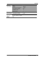
Insulation
30
Between
base
terminal
Between
base
AC
power cord
SPD3000 User Manual
and
and
20MΩor above
(DC 500V)
30MΩor above
(DC 500V)
SIGLENT
Operating
environment
Indoor
Altitude
Environment temperature
Comparative humidity
Installation level
Pollution level
≤2000 m
0 ~ 40℃
80%
Ⅱ
2
Storage
environment
Environment temperature
Comparative humidity
-10 ~ 70℃
≤ 70%
Power supply
AC 100V/120V/220V/230V±10%, 50/60Hz
Dimension
275mm x 225mm x 136mm
Weight
8kg
SPD3000 User Manual
31
SIGLENT
Chapter 5 Troubleshooting
Question 1: what to do if there occurs a short circuit on output terminal?
Answer1: There are over current protection and short circuit protection inside
the power, so current will be controlled in safety range.
Question 2: Is it abnormal that the CH3 overload indicator is lit ?
Answer 2: No, that only means the current value reaches 3A, which
is the maximum
value
within
its
range,
and
now
power
supply can be used continuously with the suggestion that decrease the
output load.
Question 3: Is it normal that in the series mode, voltage and current value of a
channel is respective 0V and not 0A, while that of another channel is both
not 0?
Answer 3: Yes, because when current output load is higher than the limited
current value, the working mode turns to CC from CV.
Question 4: How to deal with the upgrade failed?
Answer 4: please do it again.
Question 5: why the practical value is not the same with the
set value (over
performance standard) and even changes slowly on startup?
Answer 5: It’s normal. On startup, components inside the instrument are in the
process of getting stable, readings will be stable about 30 minutes later.
32
SPD3000 User Manual
SIGLENT
Chapter 6 Service and Support
Maintain summary
SIGLENT warrants that the products that it manufactures and sells will be free
from defects in materials and workmanship for a period of three years from the
date of shipment from an authorized SIGLENT distributor. If a product or CRT
proves defective within the respective period, SIGLENT will provide repair or
replacement as described in the complete warranty statement.
To arrange for service or obtain a copy of the complete warranty statement,
please contact your nearest SIGLENT sales and service office.
Except
as
provided
in
this
summary
or
the
applicable
warranty
Statement, SIGLENT makes no warranty of any kind, express or implied,
including without limitation the implied warranties of merchantability and
fitness for a particular purpose.
liable
for
indirect,
special
In
no
Event
shall
SIGLENT
be
or Consequential damages
Contact SIGLENT
MTR Add: 3/F, Building 4, Antongda Industrial Zone, 3rd Liuxian Road,
68 District, Baoan District, Shenzhen, P.R. CHINA
Tel: +86-755-36615186
E-mail:[email protected]
http://www.siglent.com
SPD3000 User Manual
33
SIGLENT
Appendix A: Accessories
SPD3000 Series Programmable DC Power Supply Accessories:
Standard Accessories:
34
A User Manual
A Certification
A Guaranty Card
A CD(including EasyPower computer software system)
A Power Cord that fits the standard of destination country
A USB Cable
SPD3000 User Manual