1
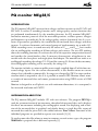
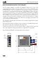
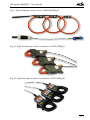
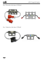
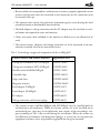
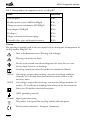
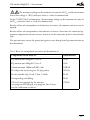
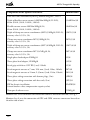
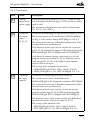
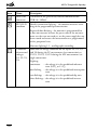
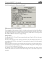
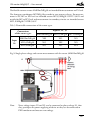
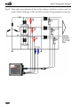
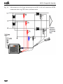
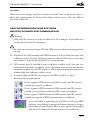
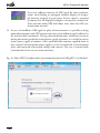
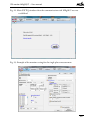
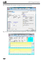
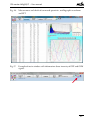
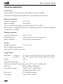
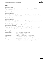
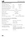
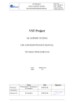
PQ monitor MEg38/C
User manual
Měřící Energetické Aparáty, a.s.
664 31 Česká 390
Czech Republic
PQ monitor MEg38/C – User manual
PQ monitor MEg38/C
INTRODUCTION
The PQ monitor MEg38/C measures four voltages and four currents on the LV, MV and
HV level. It realizes a recording function and a voltage quality analysis function that
are performed simultaneously. In the recording function, the PQ monitor MEg38/C,
hereinafter monitor, processes all of the measured quantities, evaluates powers, energies
and harmonics up to order 64. In the voltage quality analysis function of class A, it evaluates all parameters specified by the standard for the measured three voltages and three
currents. It evaluates harmonics and centred groups of interharmonics up to order 125.
While recording events, it records not only the course of URMS1/2 and IRMS1/2 but it makes
also an oscillographic recording of all four voltages and currents. The user SW working
above the recording function can evaluate the size of the capacitive compensation battery
and specifies the circuit-breaker value. It measures characteristics of appliances in connection with the three-phase and single-phase load adapter. The monitor can work as an
oscillograph recording the voltages U1–U4 and the currents I1–I4 into the data memory;
the oscillographic recording can be started by the voltage U4.
The monitor includes an uninterruptible power supply supplied from all of the four measured voltage inputs. For the current measurement, it uses flexible sensors or current
clamps that it identifies automatically. Its ranges are changed by SW. For time synchronisation which is required in calss A it is possible to connec GPS. Monitor allows remote transfer of measured data and remote parameterisation using GPRS service of GSM
network.
Monitor is designed in an all-plastic case with minimum dimensions, it is waterproof, it
has increased insulation and CATIV.
INFORMATION ABOUT SW
The PQ monitor MEg38/C includes CD with user software. The program SW PQ is
used for parameterization of measurement, download of measured data and it displays
the direct measurement including the oscillographic record. For displaying and evaluation of the measured data in graphical and tabular form in a single data file, export of
measured data and the print task is the unified software Data Viewer. Functions of the
individual programs are specified in separate user manuals [1], [2].
To analyse more data files of one or more instruments even of various types, the program
WebDatOr is prepared that is delivered separately [3].
3
Měřící Energetické Aparáty
BASIC INFORMATION ABOUT THE SET MEg38/C
The PQ monitor MEg38/C set includes the MEg38/C monitor unit in Fig. 1 with
uninterruptible power supply and current sensors in three versions. The flexible sensors
AMOSm/MEg38 in Fig. 2 are intended for LV measurements. Clamp-on transformers
are delivered in two precisions of measurement. MT0,5/MEg38 in Fig. 3a has precision of current measurement 0.5 % In and are intended for measurement in secondary
circuits of instrument transformers and also for LV measurement in category CAT IV.
MT1.0/MEg38 in Fig. 3b has precision 1.0 % In and can be used for measurements in
secondary circuits of instrument transformers and for LV measurements in category
CAT III. MT1.0/MEg38 has smaller outer dimensions with bigger inner diameter for
easier installation to measured circuit.
The single-phase and three-phase load adapter can be used for testing of electrical appliances; see Fig. 4 and 5.
For connection of monitor to voltages in large switchgears are intended voltage extensions and the LV adapter for a single-phase socket Fig. 6 and 7.
Optional accessories in the set are also: magnetic contacts, voltage extensions, grips with
fuses and an adapter for voltage measurements in a single-phase LV plug socket.
Fig. 1: PQ monitor MEg38/C, basic dimensions and user elements
4
PQ monitor MEg38/C – User manual
Fig. 2: Triple of flexible current sensors 3AMOSm/MEg38
Fig. 3a: Triple of clamp-on current transformers 3MT0,5/MEg38
Fig. 3b: Triple of clamp-on current transformers 3MT1,0/MEg38
5
Měřící Energetické Aparáty
Fig. 4: Three-phase load adapter 3Z/MEg38
Fig. 5: Single-phase load adapter Z/MEg38
6
PQ monitor MEg38/C – User manual
Fig. 6: Voltage extensions
Fig. 7: LV adapter
66
48
39,5
7
Měřící Energetické Aparáty
SAFETY INFORMATION
• It is necessary to pay close attention to these information.
• The warning points out facts, which represent safety risks for the operator.
• The cautions specify conditions and facts, which can damage the monitor.
Warning
• Watch out! The operator installing the current sensors on live parts must be
equipped with protective and other safety equipment and must use them during the installation.
• When the PQ monitor MEg38/C is used in a different way than it is specified
by the manufacturer, the protection provided by the PQ monitor MEg38/C can
be impaired.
• The operators installing and removing components of the PQ monitor set must be
qualified for live-line working and working near dangerous voltages. They must be
as well trained for the first aid treatment.
• The monitor may be operated only by qualified persons provided with protective
equipment against electric shock.
• It is not allowed to connect voltage measuring cords to phase voltages higher than
450 VAC and line to line voltages higher than 780 VAC; otherwise there is a risk of
electric shock.
• In LV networks between MV/LV transformers and energy meters of customers characterized by the overvoltage category CATIV, it is not allowed to connect the monitor to phase voltages higher than 300 VAC; otherwise there is a risk of electric shock.
• When the top insulation layer of the sensing part of the flexible sensor alone is mechanically damaged, which can prove with a contrast change of the surface colour of
the sensing part, or when the monitor or its accessories are damaged, the damaged
part must be immediately removed and sent for repair.
• Only the manufacturer or service firms trained by the manufacturer may service and
repair the monitors.
• Because of loss of waterproofness and moisture resistance, the monitor unit must
not be opened.
8
PQ monitor MEg38/C – User manual
• Because of loss of waterproofness and moisture resistance, properly tightened current
sensors and antennas must be connected to the connectors or the connectors must
be covered with caps.
• The operator must ensure the protection of monitor against water during the local
parameterization or download of measured data.
• The load adapters, voltage extensions and the LV adapter may be used only in covered rooms not exposed to water and moisture.
• Other accessories than included in the monitor set delivery are not allowed to be
used.
• The current sensors, adapters and voltage extensions are to be connected to the monitor first and only then to the measured circuits.
Tab. 1: Overvoltage category of components of the set MEg38/C
Current sensors and contact elements
Application area
Clamp-on transformer MT0,5/MEg38
CATIV / 300 V
Clamp-on transformer MT1,0/MEg38
CATIII / 300 V
Flexible sensor AMOSm/MEg38
CATIV / 300 V
Crocodile clips
CATII / 1000 V
Grips with fuses
CATIII / 1000 V
Magnetic contacts
CATIII / 1000 V
Load adapter Z/MEg38
CATII / 250 V
Load adapter 3Z/MEg38
CATII / 415 V
LV adapter
CATII / 600 V
Voltage extensions with banana plugs
CATII / 600 V
• The current sensors AMOSm/MEg38 and MT/MEg38 may be installed only on
insulated parts of conductors. When the current sensors are to be installed on an
uninsulated part, they may be installed only into circuits of the overvoltage category according to Tab. 1 that are off during the installation. When the sensors are
installed into environment with dangerous voltages, it is necessary to use protective
equipment and meet safety requirements applicable for the given network.
9
Měřící Energetické Aparáty
Tab. 2: Waterproofness of components of the set MEg38/C
Name
Protection
Unit MEg38/C
IP 65
Flexible current sensors AMOSm/MEg38
IP 65
Clamp-on current transformers MT/MEg38
IP 20
Load adapters Z/MEg38
IP 20
LV adapter
IP 20
Voltage extensions with banana plugs
IP 20
Crocodile clips, grips and magnetic contacts
IP 20
Caution
The meaning of symbols used in the user manual and in descriptions of components of
the PQ monitor MEg38/C set:
Note in the documentation / Warning, risk of danger
Warning, risk of electric shock
Do not attach around uninsulated dangerous live wires that can cause
electric shock, burns or arc discharge
Attaching around uninsulated hazardous live conductors allowed
CAT IV
Overvoltage category characterizing a transient overvoltage condition.
Generally, a LV network from the transformer station to fuses at the
electricity meter
CAT III
Overvoltage category characterizing a transient overvoltage condition. Generally, a LV installation in buildings behind fuses of the electricitymeter
Safety class II, double or increased insulation
GND, grounding terminal
IP code
Ingress protection rating
The product is designated for recycling and for collection points
Declaration of conformity – European Community
10
PQ monitor MEg38/C – User manual
The maximum voltage to the common wire may be 450 VAC and the maximum
line to line voltage is 780 V; otherwise there is a risk of a monitor fault.
In the CATIV / 300 V environments, the maximum voltage to the common wire may be
300 VAC; otherwise there is a risk of a monitor fault.
Because of loss of waterproofness and moisture resistance, the monitor unit must not be
opened.
Because of loss of waterproofness and moisture resistance, there must be connected appropriate components (current sensors, antennas) or the connectors must be covered with
caps.
The operator must ensure the protection against water during loacal parameterization or
data download.
Tab.3: Basic set and optional accessories of the monitor set
Components of the basic set
Identification
PQ monitor unit MEg38/C, class A
A/38
PQ monitor unit MEg38/C, class S
S/38
Communication USBmini/EMC cable
USB/38
LV adapter for measuring in a LV plug socket
NN/38
Set of crocodile clips (3 red, 1 blue, 1 black)
K/38
Transport bag with filling
B/38
CD with user manuals for the monitor,
user program SW MEg38, user program Data Viewer
and the calibration certificate
CD/38
11
Měřící Energetické Aparáty
Components of the optional accessories
Identification
GPS and GPRS functionality for PQ monitor Meg38/C, class S
Triple of flexible current sensors 3AMOSm/MEg38, I1-I2-I3,
40 cm (100 A, 300 A, 1 000 A, 3 000 A)
3AMOSm/38
Flexible current sensor AMOSm/MEg38, I4,
40 cm (100 A, 300 A, 1 000 A, 3 000 A)
AMOSm/38
Triple of clamp-on current transformers 3MT0,5/MEg38, I1-I2-I3,
accuracy class 0.5 (1 A, 5 A)
3MT0,5/38
Clamp-on current transformer MT0,5/MEg38, I4,
accuracy class 0.5 (1 A, 5 A)
MT0,5/38
Triple of clamp-on current transformers 3MT1,0/MEg38, I1-I2-I3,
accuracy class 0.5 (1 A, 5 A)
3MT1,0/38
Clamp-on current transformer MT1,0 / MEg38, I4,
accuracy class 0.5 (1 A, 5 A)
MT1,0/38
Single-phase load adapter Z/MEg38
Z/38
Three-phase load adapter 3Z/MEg38
3Z/38
Set of grips with fuses CAT III (3 red, 2 black)
G/38
Set of magnetic contacts Ø 7 mm, L 10 mm, (3 red, 1 blue, 1 black)
M7/38
Set of magnetic contacts Ø 11 mm, L 35 mm, (3 red, 1 blue, 1 black)
M11/38
Three-phase voltage extension with banana plugs, (2 m)
3PB/38
Three-phase voltage extension with free ends, (2 m)
3PV/38
SW for electric installation
(circuit-breaker value, compensation capacity value)
EMSW/38
Transport leatherette case
T/MEg38
Monitor class S has connectors and indication elements located on one side; see Fig. 1.
Monitor class A uses for connection of GPS and GSM antennas connectors located on
the other side of unit.
12
PQ monitor MEg38/C – User manual
Tab. 4: User elements
Item
Name
Description
Voltage
Connected measuring cords U1, U2, U3, U4 and N, long
inputs with
1 m and ended with banana plugs CATIV, which are power
power supply cords as well.
The maximum voltage between the cord N and the cords
U1, U2, U3, U4 is 450 VAC.
Connector
of current
inputs
I1, I2, I3
Connector for connecting the triple of current sensors I1, I2, I3.
The current sensors can be the flexible 3AMOSm/MEg38,
see Fig. 2, or the current clamps 3MT/MEg38, see Fig. 3.
The connected sensor type is identified automatically when
the measurement is parameterized.
Only identical sensor types may be used on the current input I1, I2, I3 and I4 of the monitor (SW check distinguishes
AMOSm/MEg38, MT0,5/MEg38 and MT1,0/MEg38).
Only identical nominal current values may be set by the
program on the current input I1, I2, I3. Nominal current
value on input I1, I2, I3 can be different than nominal
current value on I4 input.
SW settings of the nominal current values:
– 3AMOSm/MEg38 (100 A, 300 A, 1 000 A, 3 000 A)
– 3MT0,5/MEg38 (1 A, 5 A), 3MT1,0/MEg38 (1 A, 5 A)
Connector
of current
input I4
Connector for connecting the current sensor I4
The current sensor can be the flexible sensor
AMOSm/MEg38 or the clamp-on transformer MT/MEg38
The connected sensor type is identified automatically when
the measurement is parameterized.
Only identical sensor types may be used on the current
input I4 and the input I1, I2, I3 (SW check distinguishes
AMOSm/MEg38, MT0,5/MEg38 and MT1,0/MEg38).
The nominal current value on the input I4 may differ from
the nominal current value on the input I1, I2, I3
SW settings of the nominal value:
– AMOSm/MEg38 (100 A, 300 A, 1 000 A, 3 000 A)
– MT0,5/MEg38 (1 A, 5 A), MT1,0/MEg38 (1 A, 5 A)
13
Měřící Energetické Aparáty
Item
Name
Description
Mini USB
connector
Connector of the galvanically isolated communication
USB 2.0 / 3 Mbit/s.
RUN LED
condition
Shortly intermittent lighting – the monitor measures according to the programmed parametrization.
Repeated short flashing – the monitor is programmed but
it does not measure because the preset time of the measurement start has not occurred yet, or the power supply has not
been turned on because the measurement was programmed
with a postponed start.
Alternate lighting 1:1 – oscillographic recording.
�
14
Condition
of measured
voltages
U1, U2, U3,
U4
Indication of voltage conditions on the inputs U1, U2, U3
and U4 during the LV measurement (star-connection) or
U1-U2, U2-U3, U3-U1 during the MV measurement (triangle-connection).
Lighting:
continuous – the voltage is in the predefined tolerance
zone (0.9 Un to 1.1 Un)
one flashing – the voltage is in the predefined interruption
zone
two flashings – the voltage is in the predefined dip zone
three flashings– the voltage is in the predefined increase
zone
PQ monitor MEg38/C – User manual
Fig. 8: Rating plate of the PQ monitor MEg38/C
Explanatory notes to the rating plate
The rating plate of the monitor, see Fig. 8, is placed on the monitor back side. In addition
to the identification data of the manufacturer and of the monitor, it specifies the AC supply voltage range from 52 V to 440 V with the frequency 50 Hz and the consumption for
the nominal and limit values of the supply voltage.
Voltage inputs:
The voltages U1, U2, U3 and U4 are measured to the input N on the LV level; the nominal value is 230 VAC.
The line to line voltages U1-U2, U2-U3 and U3-U1 with the nominal value 100 V are
measured on the MV level; the voltage U4 is measured to the input N with the nominal
value 100/√3 V.
The LV or MV measurement is selected when the measurement is parameterized. The measured voltages are supply voltages as well. The maximum voltage on the voltage inputs
U1, U2, U3 and U4 towards N is 450 VAC.
The flexible current sensors AMOSm/MEg38 with the nominal value 100 A, 300 A,
1 000 A and 3 000 A are connected to the current inputs I1, I2, I3 and I4 usualy in LV
networks.
15
Měřící Energetické Aparáty
For measurement of currents with nominal value 1 A and 5 A usualy in secondary circuits
of instrument current transformers but also for measurement in LV circuits are designated current clamps MT0,5/MEg38. Current clamps MT1,0/MEg38 are designated for
measurement of current with nominal value 1 A, 5 A in secondary circuits of instrument
transformers or LV circuits of measurement category CAT III.
The current sensors AMOSm/MEg38 and MT/MEg38 may be installed only on insulated parts of conductors. When the current sensors are to be installed on an uninsulated
part, they may be installed only into circuits of the overvoltage category according to
Tab. 1 that are off during the installation. When the sensors are installed into environments with dangerous voltages, it is necessary to use protective equipment and meet
safety requirements applicable for the given network.
The measuring range of the current sensors is up to 1.2 In.
In the network environment with the overvoltage category CAT IV, the voltage can be
measured only up to 300 VAC.
The IP65 protection of the monitor is ensured when the caps of the USB connector, connector I1, I2, I3, connector I4 and with A version also antenna connectors are properly
tightened or the current sensors and antennas are properly tightened.
When using current sensors MT/MEg38, voltage extensions, load adapters and the LV
adapter designated for installation only in covered rooms, the operator of the monitor
must ensure the protection against water in a different manner.
Also during local parameterization of measurement and download of data using communication cable USBmini/EMC, the operator must ensure the protection against water on
the connector in a different manner.
The PQ monitor MEg38/C set is calibrated with the current sensors whose serial numbers
are stated in the bottom part of the rating plate. The measurement accuracy specified in
the technical specification is guaranteed only in this set.
16
PQ monitor MEg38/C – User manual
CHARACTERISTICS OF THE MONITOR DESIGN
The square shape monitor unit of the safety class II with indication elements and connectors on the narrow front side is designed with an optimum rectangular format in the
completed assembly for uncluttered installation into energetics switchgears.
Plastic, insulating and self-extinguishing case of the monitor unit and non-conducting
surface of components of the set.
The waterproof and dustproof design of the monitor case with waterproof current connectors when current sensors are installed or covered by the attached caps.
Voltage cords with double insulation long 1 m, good flexible also under negative temperatures, with colour coding (U1, U2, U3 and U4 are red, N is black), ended with safe
banana plugs CATIV/300V.
Measurement of the currents I1, I2, I3 with separate sensor triplet and the current I4 with
a standalone sensor, all approved for instalation into LV switchgears, with 2 m cables with
good flexibility also under negative temperatures.
Purpose differentiated, mutually not interchangeable, automatically identified current
sensors with SW switching of measuring ranges, in flexible version and in clamp-on
transformer version:
• Flexible sensors AMOSm/MEg38 of the safety class II for installation on the LV level
is all-insulating, waterproof; overvoltage category CATIV/300V with the sensing
part long 40 cm; range of measured currents from 100 A to 3000 A; sensing part
closure allows opening with just one hand.
• Clamp-on transformers MT0,5/MEg38 with overvoltage category CATIV/300V for
measurements in covered environments, with accuracy class 0.5 for direct and also
indirect measurements of currents with nominla value 1 A and 5 A on the LV, MV
and HV level or clamp-on transformers MT1,0/MEg38 with overvoltage category
CATIII / 300 V for measurement in covered environments, with accuracy class 1.0
of current with nominal value 1 A and 5 A indirectly on MV or HV voltage level or
directly on LV level with overvoltage category CAT III.
Definition of measurement accuracy of the monitor set when using components with the
identified serial numbers.
Extension of monitor set using adapters, voltage extensions and contact elements allowing
that the monitor can be used in various operating conditions.
Uninterruptible long-time secured power supply unit supplied through measuring cords
U1, U2, U3 and U4 by AC or DC voltage of a wide range.
17
Měřící Energetické Aparáty
GPS time synchronization of internal clock and bidirectional remote transfer of data
using GPRS service with class A monitor in basic configuration and optionally with class
S monitor. Both antennas are with insulation cover and has increased insulation of part
of cable.
MEASURING CONNECTION
With the monitor in LV networks, the voltages are measured directly and currents can be
measured directly or indirectly.
The measurement in MV and HV networks is indirect through instrument measuring
transformers.
For the three-phase voltage measurement, the voltages U1, U2 and U3 must be connected
in the left-rotating direction, at which the instrument is calibrated.
For the single-phase measurement, the reference input U1 must be always connected to
the measured voltage.
Not connected voltage inputs U2, U3 and U4 can be also connected to the measured
voltage and then they participate in the monitor power supply or can be connected to
the central wire N or PEN; then they show the defined zero voltage. When the unused
voltage inputs are left unconnected, then their voltage is not defined due to their high
input resistance and the voltage channel connection.
The monitor is supplied from the measured voltages. When the power of the instrument
transformer is higher than or equals 30 VA, then the measurement is not influenced due
to its loading.
During measurement on the MV level and the voltage input U4 is not used, it is recommended to connect the AC supply voltage 230 VAC or the DC supply voltage 220 V DC or
eventually 110 V DC to this input.
For measurement on the LV level, the monitor set includes load adapters, which can
be used for measuring parameters of single-phase or three-phase appliances including
harmonics and oscillographic recordings during the turning on and off. For the phase
voltage measurement in a LV single-phase plug socket, the LV adapter can be used.
Versions of the sensors AMOSm/MEg38 a MT/MEg38 cannot be confused during the
installation and the sensor types AMOSm/MEg38, MT0,5/MEg38 and MT1,0/MEg38
are automatically identified by SW. The identification is executed when the measurement
is started and when the measurement is restored after a power outage, and therefore it is
not allowed to change the types of installed sensors in the course of the measurement.
For measurement of the currents I1, I2, I3 and the current I4, it is allowed to use only
current sensors of the same type; see Tab. 5.
18
PQ monitor MEg38/C – User manual
The flexible current sensors AMOSm/MEg38 are intended for measurement on LV level.
The clamp-on transformers MT/MEg38 are made in two accuracy classes. For measurements in LV, MV or HV level are intended sensors MT0,5/MEg38 CAT IV / 300 V and
mainly for MV or HV level and measurement in secondary circuits are intended sensors
MT1,0/MEg38 CATIII / 300 V.
Tab. 5: Permissible connections of the sensor types
Connections
of the sensor types
Input
I4
Input I1, I2 , I3
AMOSm/MEg38
MT0,5/MEg38
MT1,0/MEg38
AMOSm/MEg38
YES
NO
NO
MT0,5/MEg38
NO
YES
NO
MT1,0/MEg38
NO
NO
YES
Fig. 9: Single-phase voltage and current measurement with the sensor 3AMOSm/MEg38
Note: Note: voltage inputs U2 and U3 can be connected to phase voltage L1, then
they participate on power supplying of device or they can be connected to
PEN conductor and measure zero voltage.
19
Měřící Energetické Aparáty
Fig. 10: Single-phase voltage measurement and direct current measurement with the
clamp-on transformer 3MT0,5/MEg38
Fig. 11: Single-phase voltage and current measurement and neutral conductor voltage
measurement to ground and neutral conductor current measurement
20
PQ monitor MEg38/C – User manual
Fig. 12: Three-phase voltage and three-phase current measurement with the sensors
3AMOSm/MEg38
Fig. 13: Three-phase voltage measurement and measurement of the voltage between
the neutral conductor and ground, three-phase current measurement and
measurement of neutral conducotr current with sensors 3AMOSm/MEg38
and AMOSm/MEg38
21
Měřící Energetické Aparáty
Fig. 14: Three-phase voltage measurement and direct three-phase current measurement with the sensors 3MT0,5/MEg38
Fig. 15: Single-phase voltage measurement in a LV plug socket
22
PQ monitor MEg38/C – User manual
Fig. 16: Measurement of phase voltages and current and voltages between the neutral
conductor and ground with the single-phase load adapter Z/MEg38
Fig. 17: Measurement of phase voltages, measurement of neutral conductor voltage to
ground and measurement of phase currents of an appliance with the threephase load adapter 3Z/MEg38
23
Měřící Energetické Aparáty
Fig. 18: Three-phase measurement of line to line voltages and phase currents with the
sensors 3MT1,0/MEg38, in MV and HV networks with grounded neutral point.
24
PQ monitor MEg38/C – User manual
Fig. 19: Measurement of line to line voltages, U0 voltage and phase currents with the
sensors 3MT0,5/MEg38 in a compensated MV network
25
Měřící Energetické Aparáty
Fig. 20: Measurement in the Aron connection on the MV level with connected GPRS
communication ang GPS time synchronization
26
PQ monitor MEg38/C – User manual
MEASURED DATA
The amount of measured data depends on the measuring connection and parameterization of the measurement. The measured data are divided into data of continuous voltage
quality phenomenona, data of one-time voltage events and recorder data.
Data of continuous voltage quality phenomenona (aggregation interval 10 min):
-
Time period of evaluation
-
Voltage unbalance
-Frequency
-Voltage
-
Voltage deviations Uover, Uunder
-
Flicker Pst and Plt,
-THDU
-
DC component, basic up to 125th voltage harmonic
-
Centred groups of interharmonic voltages up to order 125
-
Voltage signals level
-
Identification of flagged values
-Currents
-
Basic up to 125th current harmonic
-
Centred groups of interharmonic currents up to order 125
Data of one-time voltage events:
-
Event occurrence time
-
Event duration time
- Times when limits of interruption, voltage and current dips and swells were exceeded
-
Residual and maximum voltages and currents
-
Time courses of voltage values URMS1/2 and current values IRMS1/2
-
Oscillogram of voltage and current waveforms during the event
-
Voltage and current harmonics during the event
27
Měřící Energetické Aparáty
Recorder data (aggregation interval from 1 sec to ¼ hour according to the measurement
parameterization):
- Time period of evaluation
-Voltages
-Currents
- Active powers
- Reactive powers
- Apparent powers
-PF
- Active and reactive energies – four quadrants, 6 registers for each phase
- Distortion powers
- Unbalance power
- Active powers of 1st harmonics
- Reactive powers of 1st harmonics
- Apparent powers of 1st harmonics
-Cos φ
- Active and reactive energies of 1st harmonic – 4 quadrants, 6 registers fo each phase
-THDU
-THDI
- Voltage harmonics up to order 64
- Current harmonics up to order 64
- Active and reactive energy (6 registers for a phase)
The above mentioned data of the continuous voltage quality phenomenons are specified
for the voltages U1, U2, U3 and the currents I1, I2, I3.
The above mentioned data of the recording of one-time events started from the time
when the defined limits for U1 – U4 and currents I1 – I3 were exceeded, are recorded for
all given quantities.
The above mentioned recorder data are for the voltages U1 – U4 and the currents I1 – I4.
28
PQ monitor MEg38/C – User manual
COMPLETION OF THE MONITOR SET, PREPARATION OF THE MEASUREMENT
Warning
• The maximum connected phase voltages may be 450 VAC, the maximum connected
deltaline to line voltages are 780 VAC.
• In the CATIV / 300 V environments, the maximum voltage to the common wire may
be 300 VAC.
• For completion of the monitor before the measurement, only accessories included in
the monitor set according to the approved overvoltage category in accordance with
the overvoltage category in the measured point are allowed to be used.
• It is necessary to interconnect all of the components of the set before connecting to
the measured voltages.
• It is recommended not to expose the monitor and the current sensors AMOSm/MEg38
to water and moisture.
• The clamp-on transformers MT/MEg38, voltage extensions, load adapters and LV
adapter may not be exposed to water and moisture.
• For electric shock protection, the voltage cords must be provided with contact elements included in Tab. 1 or inserted into safe terminals of adapters or extensions
before they are connected to the voltage. Magnetic contacts may be only installed on
turned off voltage circuits with zero voltage.
• In LV switchgear with danger of touch with live parts is possible to plaec only parts
of antenna with reinforced insulation
Caution
• The PQ monitor MEg38/C set is calibrated with the current sensors whose serial
numbers are stated in the bottom part of the rating plate. The measurement accuracy
specified in the technical specification is guaranteed only in this set.
• When the voltage is measured using adapters or voltage extensions, the voltage cords
U1–U4 and N of the monitor are to be inserted into the marked safe terminals.
Otherwise, the voltage cords of the monitor are to be installed either using crocodile
clips or grips with fuses or magnetic contacts.
• When connecting GPS and GSM antennas, which have equivalent connector, it is
necessary to pay attention to its correct connection. When antennas are not used,
then connector must be properly tightened with caps in order to ensure waterproofness.
29
Měřící Energetické Aparáty
• During local parameterization of measurement and download of data using communication cable USBmini/EMC, the operator must ensure the protection against
water on the connector in a different manner.
For current measurements, identical types of the current sensors, either the flexible sensors
AMOSm/MEg38 or the clamp-on transformers MT0,5/MEg38 or clamp-on transformers MT1,0/MEg38 are to be connected to the current connector I1, I2, I3 and eventually to the current connector I4. The connector nuts or caps are to be properly tightened.
If the currents are not measured, the connector caps are to be properly screwed on one or
both of the current connectors.
In LV networks are usualy connected to current inputs I1, I2, I3 and I4 flexible current
sensors AMOSm/MEg38 with the nominal value 100 A, 300 A, 1 000 A and 3 000 A.
For measurement of currents with nominal values 1 A or 5 A are also in LV networks
intended current clamps MT0,5/MEg38 in overvoltage category CAT IV / 300 V and
current clamps MT1,0/MEg38 in overvoltage category CAT III / 300 V.
The communication cable USBmini/EMC is to be connected to the opened communication USB connector of the monitor and its other end is to be connected to the USB
connector of PC with the running parameterization program SW PQ as instructed in its
user documentation [1].
Connect GSM and GPS antennas to class A monitor and optionally also class S monitor
according to figure 20. Pay attention to not interchange antennas!
CONNECTION TO THE VOLTAGE
Warning
• It is not allowed to connect voltage measuring cords to phase voltages higher than
450 VAC; otherwise there is a risk of electric shock.
• It is not allowed to connect the monitor to line to line voltages higher than 780 VAC;
otherwise there is a risk of electric shock.
• In LV networks between MV/LV transformers and electricity meters of customers
characterized by the overvoltage category CATIV, it is not allowed to connect the
monitor to phase voltages higher than 300 VAC; otherwise there is a arisk of electric
shock.
• The monitor must be operated only by qualified persons provided with protective
equipment against electric shock.
30
PQ monitor MEg38/C – User manual
• The voltage extensions, load adapters and LV adapters must not be exposed to water.
• The operating voltage range is from 52 V~ to 440 V~.
•If the monitor or its measuring cords are damaged mechanically, it is needed to
dismount the monitor immediately and send for repair.
1. The voltage cords, first N and then U1–U4 are to be connected to the measured
voltages according to the measuring diagrams in Fig. 9 – Fig. 20. If needed, then
crocodile clips, magnetic contacts, adapters or voltage extensions are to be used.
2. During the measurement, the measuring cord U1 of the reference channel of the
monitor must be always connected to the measured voltage.
3. The LED RUN lights up according to the programmed measurement mode, see
Tab. 4.
4. The LEDs U1, U2, U3 and U4 light up according to voltages in the way specified
in Tab. 4.
CONNECTING THE CURRENTS AND CHECK OF CORRECT WIRING
Warning
• The current sensors AMOSm/MEg38 and clamp-on transformers MT/MEg38 are
allowed to be installed only in circuits with the overvoltage category specified in
Tab. 1.
•Even if only the top insulation layer of the sensing part of the flexible sensor
AMOSm/MEg38 is mechanically damaged, which can prove with a contrast change
of the surface colour of the sensor, the sensor must be immediately removed and sent
for repair.
• The current sensors are intended only for installation on insulated live parts.
• When the current sensors are installed in space with dangerous voltages, it is necessary so that the operator is provided with protective equipment against electric shock.
• When the current sensors must be installed on live parts or in space with dangerous voltages, it is necessary to perform its installation in deenergized state without
voltage and meet safety requirements and regulations applicable in the respective
distribution network.
31
Měřící Energetické Aparáty
• If the currents are not measured, the connector caps are to be properly screwed on
both of the current connectors
• When the clamp-on current transformers MT/MEg38 are used, the monitor operator must ensure the protection against water on the sensing part of the clamp-on
sensors MT/MEg38 in a different way.
5. The current sensors are to be installed on the wires with the measured current so that
their arrows show the direction of current flow to the load.
6. On PC with the running program SW PQ, see Fig. 21, there is a pictogram of the
established communication with the monitor, FW version and serial number displayed in the dropdown menu on the right side of window. Labels of all buttons of the
window are in bold.
When the program SW PQ is running and the monitor is not connected to PC or is
connected incorrectly, the window will be displayed with an empty field confirming
the communication and the buttons labels will not be in bold; see Fig. 22.
7. The bold button Settings MEg opens measurement parameterization and the single-phase or three-phase measurement, voltage level, type and conversion ratio of the
current sensors and possibly other parameters of the measurement are to be selected
according to the measuring diagram.
Fig. 23 shows an example of parameterization of the single-phase measurement with
the clamp-on transformers MT/MEg38 on the currents I1 and I4.
Fig. 24 shows an example of parameterization of the three-phase measurement with
the flexible sensors AMOSm/MEg38 on the currents I1–I4.
8. After the button Start of measurement is enabled and the data measured until now
are deleted, the measurement will be started according to the new selected parameterization. Using menu button Measurement with RMS selection displays window
with values of measured voltages and currents, its time courses and phasor diagram
of powers. Example is on Fig. 25. This way can be checked correct direction of installation of current sensors.
9. Using menu button Measurement with selection Samples displays harmonic component of measured voltages and currents, oscillographic waveforms and phasor diagram displaying orientation of currents and voltages. Example is in Fig. 26.
32
PQ monitor MEg38/C – User manual
Attention!
When line to line voltages and phase currents on the MV level are measured, there is a
phase shift approximately 30° between the voltage and the current. This may differ in
case of the current I4.
TIME SYNCHRONIZATION USING GPS SYSTEM
AND SETUP OF REMOTE GPRS COMMUNICATION
Warning
• GSM and GPS antennas are to be installed out of LV switchgear. In the coiled state
can be placed also into LV switchgears.
• Pay attention to not interchange GPS and GSM antennas when connecting to monitor unit.
10. Antenna of the GSM network with GPRS function is to be installed into space with
sufficient intensity of signal. Insulation protective tube of GSM antenna with magnetic holders is to be installed preferably in vertical position.
11. GPS antenna must be installed in space with direct visibility to sky. For time synchronisation of monitor is needed to receive signal from three satelites and therefore
insulation rounded cover of GPS antenna is usualy placed in horizontal position on
window ledge with sufficient visibility to sky.
12. In main window of SW PQ are pictograms of GPRS and GPS, see Fig.27.
Meaning and use of pictograms:
Device supports GPRS function of GSM network and GPS synchronisation, but signal is insufficient.
Device supports GPRS function of GSM network and GPS synchronisation, but signal from satellites of GPS system is insufficient.
Device supports GPRS function of GSM network and GPS synchronisation, but signal for GPRS communication is insufficient.
In case of sufficient signal intensity of GSM network with GPRS
function, then clicking its pictogram (button) displays in baragraph intensity of signal in given point. Lowest signal is presented by
shortest bar. In displayed example is intensity on third level.
33
Měřící Energetické Aparáty
In case of sufficient intensity of GPS signal for time synchronisation, then clicking its pictogram (button) displays in baragraph intensity of signal in given point. Lowest signal is presented
by shortest bar. In displayed example is intensity on second level.
Date and time below GPS label shows time, when last GPS synchronisation occured.
13. In case of insufficient GPS signal in place of measurement it is possible to bring
powered on monitor with GPS antenna into space with sufficient signal and here let
the internal clock synchronize. During time synchronization, which may not occur
during one minute period of secured power supply operation, it is needed to ensure
mains power supply of monitor. After synchronisation monitor supplied from its
own internal uninterruptible power supply is to be returned back to measurement
place and connected to measured voltages and currents. This way is internal clock
synchronized at least on start of measurement.
Fig. 21: Main SW PQ window when the communication with MEg38/C is established
34
PQ monitor MEg38/C – User manual
Fig. 22: Main SW PQ window when the communication with MEg38/C was not
established
Fig. 23: Example of the monitor setting for the single-phase measurement
35
Měřící Energetické Aparáty
Fig. 24: Example of the monitor setting for three-phase measurement
Fig. 25: Measurement and check of connected quantities, course of RMS values
36
PQ monitor MEg38/C – User manual
Fig. 26: Measurement and check of connected quantities, oscillographic waveforms
and FFT
Fig. 27: Example of main window with information about intensity of GPS and GSM signals
37
Měřící Energetické Aparáty
MAINTENANCE
Caution
• Only trained and qualified personnel of the manufacturer or service organisation of
the manufacturer may repair the monitor during the guarantee period. For contact
to the manufacturer‘s service department see www.e-mega.cz.
• The monitor must not be exposed to chemicals.
• The monitor may be transported only in the original transport bags or cases delivered
by the manufacturer.
• The PQ monitors MEg38/C of class A are recalibrated every 2 years and the PQ monitors MEg38/C of class S always every 3 years after the sale or the last calibration.
When the monitor is used properly in accordance with this manual, it does not require
any special maintenance. Only when the instrument is unclean, it is suitable to clean it
with a damp cloth without any detergents.
BATTERY
The following batteries are used in the monitor:
• Lithium battery of CR2032 type for the clock circuit,
• Ni-Mh accumulator of 8xV200H type for ensuring the measurement in case of
a supply voltage outage.
• The accumulator is charging when the monitor is connected to any of measured
voltage U1 to U4.
• The duration of charging of completely discharged accumulator when power supplying from single voltage with nominal value and positive temperature is shorter
than 12 hours.
• Fully charged accumulator in positive temperatures secure at least ten successive oneminute supply intervals.
• In total range of operation temperatures the fully charged accumulator ensures during power outage at least two one-minute power supplying intervals.
• When starting monitor with fully charged accumulator after long-term power off
state and in temperature of environment -20 °C, then after short restoration of supply
voltage monitor operates for at least 10 second.
38
PQ monitor MEg38/C – User manual
DISPOSAL
After the use of the monitor is ended, the monitor must be recycled in collecting centres
according to rules for electronic waste disposal.
GUARANTEE
A two-year guarantee is provided for the monitor since the date of sale, but no more than
30 months after its dispatch from the manufacturer. Defects incurred during this period
due to provably defective construction, defective design or improper materials will be
repaired by the manufacturer or a service firm of the manufacturer free of charge.
The guarantee becomes invalid also during the guarantee period if the user carries out
unauthorized modifications or changes on the monitor MEg38/C, connects the instrument incorrectly, handles it incorrectly or roughly or the instrument is operated contrary
to the technical specification.
Defects of the monitor and its accessories incurred during the guarantee period shall be
claimed by the user to the manufacturer or the service firm authorised by the manufacturer.
In case of a guarantee and after-guarantee failure, it is useful to deliver also a description
of the failure behaviour with the defective instrument.
39
Měřící Energetické Aparáty
TECHNICAL PARAMETERS
General data
The measurement uncertainties are applicable for reference conditions.
The monitor development and production is in accordance with ISO 9001.
Reference conditions
Ambient temperature: 23 °C ± 2 K
Relative humidity:
40 % to 60 %
There is a left-rotating voltage system on the inputs U1, U2 and U3
Power supply – through the input U4 by a voltage higher than the calibrated voltages on
the inputs U1, U2 and U3.
Working conditions
Operating temperature: -20 °C to +55 °C
Stabilization time:
10 minutes after the power is turned on
Relative humidity 10 % to 90 %, no condensation
Storage
Storage temperature: -30 °C to +60 °C
Water and chemicals protection
Long-term UV radiation protection
Design details
Dimensions – version A: – version S: 167 × 130 × 35 mm, with connectors 195 × 130 × 35 mm
152 × 130 × 35 mm, with connectors 180 × 130 × 35 mm
Weight:
0.7 kg
Length of voltage cords: 1 m
All-insulated surface, Polycarbonat material, UV-resistant, inflammable
Protection: IP65 according to EN 60 529
Overvoltage category: CATIV / 300 V, CATIII / 600 V
according to EN 61010-2-030
Safety class:
II, reinforced insulation
Test voltage: 5.4 kV, 50 Hz, 1 minute
40
PQ monitor MEg38/C – User manual
EMC
EN 61326-1:2006
Electrical equipment for measurement, control and laboratory use – EMC requirements
– Part 1: General requirements
Line terminal voltages
EN 55011 ed.3:2010
Industrial, scientific and medical equipment – Radio frequency disturbance characteristics – Limits and methods of measurement
Radiated emissions
EN 55011 ed.3:2010
Industrial, scientific and medical equipment – Radio frequency disturbance characteristics – Limits and methods of measurement
Radiated radio-frequency electromagnetic field
EN 61000-4-3 ed.3:2006
Electromagnetic compatibility (EMC) – Part 4-3: Testing and measurement equipment
– Radiated, radio-frequency, electromagnetic field – Immunity test
Power supply
Supply voltage: 57.7 VAC to 400 VAC ±10 %, 50 Hz
80 V DC to 400 V DC ±10 %,
Consumption: 5 VA / 52 VAC, 8 VA / 230 VAC, 12 VA / 450 VAC
UPS operation time:
1 min (SW selectable), also multiple repetitions
Fuse type:
FSK 00.1 / 500 mA-T, only the manufacturer or service firms trained by the manufacturer may replace the fuses
41
Měřící Energetické Aparáty
Data memory
Capacity: 128 MB, NAND
Memory organisation: circular
Example of a recording range in a three-phase network
(20 % quality, 8 % recorder, 52 % events, 20 % reserve):
quality – 52 days 18 hours,
events – at least 322, with duration 3 sec,
- voltage URMS1/2, current IRMS1/2, recording interval 10 sec,
- oscillographic recording of voltages and currents, recording interval 1 sec,
recorder – 51 days 0 hours.
Note:
It is applicable for quality data of U1, U2, U3 and I1, I2, I3, for recorder data of U1, U2, U3, U4 and I1, I2, I3, I4.
The functions use the reserve part of the memory after the area defined for them was filled up.
Measuring characteristics
Sampling frequency:
256 samples per period
Antialiasing filter: digital FIR filter
Phase locked loop controlled by the fundamental voltage harmonic U1 passing through zero
Aggregation intervals: quality function – according to EN 61000-4-30, ed. 2
recorder function – from 1 sec to ¼ hour
Aggregation synchronisation: according to EN 61000-4-30, ed. 2,
Time base:
42
GPS synchronisation:
±10 ms
without GPS synchronisation: ±1 sec per 24 hours at 23 °C ± 2 K
PQ monitor MEg38/C – User manual
Measurement uncertainties and measuring ranges of voltage quality parameters
under testing states 1, 2 and 3 according to EN 61000-4-30, ed. 2.
LV and MV level, f = 50 Hz
Parameter
Class
Uncertainty
Measuring range
Frequency
A
± 2 mHz
42.5 Hz – 57.5 Hz
Voltage
A
± 0.1 % Un
10 % Un – 150 % Un
Flicker Pst
A
5 % Pst
IEC 61000-4-15, ed. 2
Pst (0.2 – 10.0)
1 – 4 000 changes/min
Flicker Pinst, max
A
8 % Pst
Pst = 1.0
sine, rectangular
Voltage events
A
Amplitude: ± 0.2 % Un
Duration: ± 1 period
5 % Un – 150 % Un
0.02 sec – 60 sec
Interruption
A
Duration: ± 1 period
0.02 sec – 180 sec
Unbalance
A
± 0.1 %
0.5 % u2 – 5 % u2
0.5 % u0 – 5 % u0
Voltage harmonics
A
5 % Uharm, Uharm ≥ 1 % Un
0.05 % Un, Uharm < 1 % Un
10 % – 200 %
of class 3
IEC 61000-2-4
Voltage
interharmonics
A
5 % Uharm, Uharm ≥ 1 % Un
0.05 % Un, Uharm < 1 % Un
10 % – 200 %
of class 3
IEC 61000-2-4
Signals in voltage
A
± 5 % Usig for
3 % Un ≤ Usig ≤ 15 % Un,
± 0.15 % Un for
1 % Un ≤ Usig ≤ 3 % Un
0.5 % Un – 15 % Un
Voltage deviations
A
± 0.1 % Un
10 % Un – 150 % Un
Time base 1)
A
± 10ms
-
Time base 2)
S
± 1 sec per 24 hours
-
1)
2)
with GPS signal synchronization
without GPS signal synchronization
43
Měřící Energetické Aparáty
Voltage inputs U1, U2, U3 and U4
SW setting of voltage level:
LV
MV and HV
Nominal phase voltages UnP-N: 230 VAC 100/√3VAC
Nominal line to line voltages UnP-P:
400 VAC 100 VAC
Measuring range of phase voltages:
440 VAC 250 VAC
Maximum input voltage P-N:
450 VAC
Voltage measurement uncertainty with f=50 Hz:0.05 % M.V. ± 0.025 % Un
Frequency range:
up to 6.5 kHz
Input resistance:
1.68 MΩ
Temperature coefficient:
Measurement:
Max. ratio of voltage transformer:
0.05 % / 10 K
directindirect
–
999 kV / 100 V (optional SW PQ)
Current inputs with flexible sensors AMOSm/MEg38
SW setting of the nominal value
Nominal current In:
100 A, 300 A, 1 000 A, 3 000 A
Measuring current range:
5 % In to 120 % In
Frequency range:
40 Hz to 6.5 kHz
Current measurement uncertainty 1), 2)
In =100 A, 300 A, 1000 A, 3000 A: 0.5 % M.V. ± 0.1 % In (45 Hz to 60 Hz)
Value change with position:
± 1.0 % M.V.
Value change due to ext. fields: ± 1.0 % M.V. ± 0.2 In (external field
produced by the conductor with 0.3 In / 50 Hz at 35 mm distance from the closure)
Temperature coefficient:
0.2 % / 10 K
44
PQ monitor MEg38/C – User manual
Harmonic measurement uncertainty
In = 100 A, 300 A, 1000 A:
± 5 % Iharm at Iharm ≥ 3 % In
and ± 0.15 % In at Iharm < 3 % Ijm 1)
In = 3000 A:
± 10 % Iharm at Iharm ≥ 3 % In
and ± 0.5 % In at Iharm < 3 % In
1)
2)
In the range from 5 % to 120 % In
With correct position of the closure
Current inputs with clamp-on transformers
MT0,5/MEg38
Nominal current In 1):
MT1,0/MEg38
1 A, 5 A
Current measurement uncertainty:0.5 % of range
1 A, 5 A
1.0 % of range
Harmonic measurement uncertainty:
± 5 % Iharm at Iharm ≥ 3 % In
and ± 0.15 % In at Iharm < 3 % In 1)
± 10 % Iharm at Iharm ≥ 3 % In and ± 0.5 % In at Iharm < 3 % In
Measuring range:
5 % to 120 % In
Measurement category: CAT IV /300 V, CAT III / 600 V
Safety class:
CAT III / 300 V
II
Protection rating: IP40 with closed jaws
IP30 with opened jaws
Working temperature:
-10 °C to +55 °C
Relative humidity:
≤ 85 %
Dimensions:
135 × 51 × 35 mm
Max. diameter of measured conductor:
20 mm
Weight:
2 kg
1)
Class I according to EN 61000-4-7 ed.2
45
Měřící Energetické Aparáty
LITERATURE
[1] User description of the program SW PQ, www.e-mega.cz
[2] User description of the program Data viewer, www.e-mega.cz
[3] User description of the program WebDatOr, www.e-mega.cz
MANUFACTURER
MEgA – Měřící Energetické Aparáty, a.s.
664 31 Česká 390, Czech Republic
Tel. +420 545 214 988
e-mail: [email protected]
web: www.e-mega.cz
46
PQ monitor MEg38/C
User manual
Měřící Energetické Aparáty, a.s.
664 31 Česká 390
Czech Republic
www.e-mega.cz
Edition: 4/2015