1
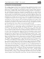
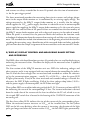
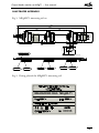
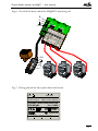
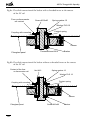
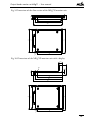
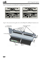
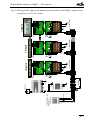
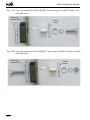
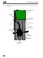
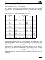
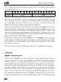
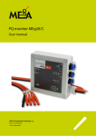
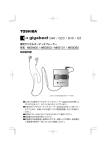
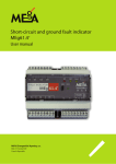
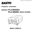
Output Feeder Monitor Set MEg71
User Manual
Měřící Energetické Aparáty, a.s.
664 31 Česká 390
Czech Republic
Output feeder monitor set MEg71 – User manual
Output feeder monitor set MEg71
1/ INTRODUCTION
The MEg71 output feeder monitor set measures voltages, currents, powers and energies
of a three-phase output feeder with a LV fuse fail or a fuse disconnector rail of a cabinet
or a station; it registers both voltage phenomena and short-circuit currents and signalizes
the status of fuses of the LV rail. It records these data into a non-volatile data memory,
displays them on its indication elements, signalizes them with its contact and when it is
on-line connected, it transfers the data to higher-level information systems.
The MEg71 output feeder monitor set comprises the MEg71 monitor unit and the
MEgML71 measuring rail. The MEg71 monitor unit is available in two versions according to the space available above the LV rails. The slim version MEg71S with indicating
LEDs is designed for cabinets with a small space above the LV rails and the version
MEg71D with a display is to be used when the space above the LV rails is sufficient.
The MEg71 monitor set measures voltages at the feeder (behind the fuses) and at the
busbars (in front of the fuses) and determines the status of the fuses from them. It measures currents in two ranges. It measures in the measuring range up to 1.2 multiple of the
rated current of the installed fuses of the LV feeder and the short-circuit currents to the
tenfold rated current at least. The MEg71 output feeder monitor set is supplied by a DC
supply voltage with a rated value of 12 V. It has a RS485 serial interface with MODBUS
protocol or a more efficient proprietary protocol for local and remote communication.
The MEgML71 measuring rail is provided with current sensors with a high instrument
security factor and electronic protection when their secondary circuits are disconnected.
The rated values of their secondary currents are reduced in order to reduce losses. It is to
be installed between busbars and the LV rail of the cabinet. It is characterized by its low
height, therefore it can be installed also additionally into already operating LV cabinets.
The MEgML71 measuring rail is designed for the most demanding working conditions
with the overvoltage category CAT IV.
The monitor unit in both versions can be reconnected to various MEgML71 measuring rails also during operation with maintaining the specified measuring accuracy and
without any risk of failure of the measuring rail due to the disconnection of secondary
circuits of its current sensors.
3
Měřící Energetické Aparáty
2/ TECHNICAL PARAMETERS
Reference conditions
Usupply = 12 V DC, ambient temperature = 20 °C, relative humidity = 40 % to 70 %
f = 50.0 Hz, measured voltages and currents with the same frequency constitute a threephase system
MEg71D or MEg71S Output feeder monitor unit
Feeder voltage, voltage of busbars (direct measurement, CATIV / 300 V)
Rated value Unom:
230 VAC
Measuring range:
5 % to 130 % Unom
Measuring accuracy: 0.2 % Unom + 0.1 % M.V. 1)
Maximum voltage:
300 V
Measured currents (direct measurement)
Rated value Inom2):
80 A AC, 160 A AC, 320 A AC, 640 A AC
Measuring range:
2 % to 120 % Inom
Measuring accuracy, InomM = 80 A, 160 A: 0.5 % InomM + 0.1 % M.V. including sensor
InomM = 320 A, 640 A: 1.0 % InomM + 0.1 % M.V. including sensor
Active power
Rated value Pnom:Unom ∙ InomM
Measuring range:
0.8 Unom ≤ U ≤ 1.3 Unom
0.02 InomM ≤ U ≤ 1.2 InomM
cos φ ≥ 0.5
Measuring accuracy, InomM = 80 A, 160 A: 1.0 % Pnom, including sensor
InomM = 320 A, 640 A: 1.5 % Pnom, including sensor
Reactive power
Rated value Qnom:Unom ∙ InomM
Measuring range:
0.8 Unom ≤ U ≤ 1.3 Unom
0.02 InomM ≤ U ≤ 1.2 InomM
cos φ ≤ 0.707
Measuring accuracy, InomM = 80 A, 160 A: 1.0 % Qnom, including sensor
InomM = 320 A, 640 A: 1.5 % Qnom, including sensor
4
Output feeder monitor set MEg71 – User manual
Active energy
Measuring range:
0.8 Unom ≤ U ≤ 1.3 Unom
0.02 InomM ≤ U ≤ 1.2 InomM
cos φL ≥ 0.5
cos φC ≥ 0.8
Measuring accuracy:
class B, including sensor
Voltage events 3), 4)
Rated value Unom:
230 VAC
Measuring range URMS1/2:
0.05 Unom ≤ U ≤ 1.3 Unom
Measuring accuracy URMS1/25):
0.5 % Unom + 0.1 % M.V.
Measuring range T
0.02 sec < T ≤ 60 sec
Measuring accuracy T5):
± 20 msec
Short-circuit currents IZ 2), 6)
Rated value InomZ:
2000 A AC, 6000 A AC
Measuring range IZ:
1.2 InomM to InomZ
Measuring accuracy IZ:
10 % M.V. including sensor
Internal time
Accuracy:
1.0 sec / 24 hrs. at ambient reference temperature
Accuracy at synchronisation of network f 7):
network T ± 1 sec
PLL (Phase Locked Loop) frequency range 8):
42.5 Hz to 57.5 Hz
Overload capacity of current inputs:
2 InomM / 1 min, 10 InomM / 1.5 sec
General data
Data memory:
4 MB + 4 MB (flash)
Data memory organization:
circular
Serial interface:
RS485, 115.2 kbit/sec
Recording interval:
from 1 sec to 15 minutes, set by SW
Maximum number of recorded events: 1024
Maximum length of recorded event course 9), 10):
Fixed pre-trigger:
10 periods
Fixed post-trigger:
20 periods
125 periods, 250 values URMS1/2
5
Měřící Energetické Aparáty
Power supply
Rated voltage:
12 V DC
Supply voltage range:
8 V DC to 15 V DC
Supply current at voltage 12 V DC:
MEg71D = 85 mA, MEg71S = 55 mA
MEg71D = 100 mA, MEg71S = 75 mA
at voltage 15 V DC:
Unit construction
Version MEg71S:
97 × 107 × 17 mm
Version MEg71D:
97 × 107 × 40.5 mm
Weight of MEg71S:
110 g
Weight of MEg71D:
140 g
Input-output connector:
type CAN 25V
Operating data of the unit
Output feeder monitor unit MEg71D and MEg71S
Working temperature:
-20 °C to +60 °C
Relative humidity:
20 % to 90 % at 40 °C
Storage temperature:
-25 °C to +80 °C
Protection rating:
IP20 – accessible parts, IP00 – inaccessible parts)
Pollution degree:
2
Safety:
EN 61010-1: 2010, EN 61010-2-030: 2010
Electromagnetic compatibility
Electrical fast transient/burst immunity test:
EN 61000-4-4: 2004
Surge immunity test:
EN 61000-4-5: 2006
Immunity to conducted disturbances,
induced by radio-frequency fields: EN 61000-4-6: 2009
Radiated emissions in the frequency
band 30 MHz – 1 GHz:
EN 55011: 2009 Art. 6.2.1
Interference voltages on supply terminals: EN 55011: 2009 Art. 6.2.2
Electric discharges (ESD): EN 61000-4-2: 2009
Radiated radio-frequency electromagnetic field: EN 61000-4-3: 2006
Voltage dips, short interruptions
and voltage variations: EN 61000-4-11: 2004
6
Output feeder monitor set MEg71 – User manual
MEgML71 Measuring rail
Current transformer
Rated primary current 11):
250 A AC, 400 A AC, 630 A AC
Security factor:
10
Rated short-time (thermal) current:
20 kA for 1 sec
Maximum voltage between
current inputs: 520 VAC
Rated frequency:
50 Hz
Frequency range:
40 Hz to 60 Hz
The secondary circuit of the current transformer can be permanently open.
Rated voltage value:
230 VAC
Input resistance of voltage inputs
of three-phase front-end resistor
(feeder voltage, voltage of busbars):
3.37 MΩ ± 1 %
Maximum input phase voltage:
300 VAC
Voltage drop on coupling of measuring rail 12)
at Inom = 640 A: < 10 mV
at Imax = 6400 A: < 100 mV
Dimensions 13):
540 × 79 × 26 mm (without three-phase front-end resistor)
560 × 79 × 26 mm (with three-phase front-end resistor)
Centre-to-centre distance of holes:
185 mm
Fastening screws 14):
M12×40 hex. h., M12×65 hex. h.
flat washer 12, spring washer 12
Specified tightening moment
of attaching screws:
28 Nm
Maximum cross-section of wires
of terminal blocks X3, X4 and X5:
1.5 mm2
Temperature range:
-40 °C, +80 °C,
temperature of busbars temporarily up to 100 °C
Protection rating:
IP 00
Maximum humidity:
95 %
Overvoltage category:
CAT IV / 300 V
7
Měřící Energetické Aparáty
Notes:
1) M.V. – measured value.
2) Only one of these values. It is derived from the rated fuse current set on the DIP
switch.
3) If uninterruptible power supply is provided.
4) It registers events with the duration T longer than 1 sec with characteristics specified
in EN 50160, ed. 3, i.e. with the residual and maximum voltage and the duration of
the voltage phenomenon.
5) It complies with Class S of EN 61000-4-30, ed. 2.
6) It is derived from the rated fuse current set on the DIP switch. The range of the shortcircuit current 2000 A is applicable to the measuring range 80 A and 160 A and the
range the short-circuit current 6000 A is applicable to the measuring range 320 A and
640 A.
The maximum duration of the short-circuit current is 1.5 sec.
7) If phase lock loop is locked.
8) When a frequency is out of the frequency range or the voltage of the L1 busbar is less
than 10 V, the frequency will be set to 50.00 Hz.
9) All the measured voltages and all the measured currents in values of U RMS1/2 and IRMS1/2
are recorded.
10)When events are longer than the maximum length of the record, extreme values in
accordance with the EN 50160, ed. 3 are recorded and evaluated after the pre-trigger
and the initial run, and after the event is ended, the values are recorded over the period
of the post-trigger.
11)Only one of these values; as specified in the order.
12)For the specified tightening torque of the attaching screws.
13)For details see Fig. 1.
14)According to versions of the LV busbars, see Fig. 8a and Fig. 8b.
8
Output feeder monitor set MEg71 – User manual
3/ DESCRIPTION OF THE WIRING AND FUNCTION OF THE MEg71
OUTPUT FEEDER MONITOR SET
The MEg71 output feeder monitor set consists of the monitor unit either in the version
MEg71D with a display or in the slim version MEg71S, which is to be attached to the
MEgML71 measuring rail. Two three-phase voltages and one phase currents are converted to LV signals via impregnated sensors and via a 3-phase front end resistor, which are
located on the measuring rail. The phase currents and 3-phase voltages of the busbars are
measured via three sensors – in front of the fuse. The 3-phase voltage at the LV feeder is
measured via an optionally installed 3-phase front-end resistor – behind the fuse.
The sensors on the measuring rail are ring-type and are designed for accurate current measuring up to 1.2 multiple of the current of the fuse rails with the rated currents 250 A, 400 A
and 630 A. Besides, the toroids have a high security factor, which also enables to measure
courses of short-circuit currents. The sensor is provided with low-loss protections, which
protect the toroid windings from overvoltage effects during the disconnection of the measuring current circuits. As fuses ranging between 40 A and 630 A are usually used on the
LV feeders, according to feeder nominal value of current (marked as IR), this nominal value
can be set on the DIP switch located in the termination of the CANNON connector of the
measuring rail. There is a memory in the termination of the CANNON connector, which
contains also other information related to the measured LV feeder.
After the output feeder monitor is connected to the CANNON connector of the measuring rail, the processor of the unit reads the data and accordingly modifies parameters of
the measurement and generates the heading of the new data file. The CANNON connector is located in the termination at the end of the folded flat cable so that the MEgML71
measuring rails can be installed during production of the LV cabinets and the monitor
units can be installed additionally after installation of power units, and also for the reason
of a possible reconnection of the output feeder monitor unit to various LV feeders. The
connector is connected using this cable in front of the panel of the LV cabinet. The CANNON connector is provided with a bolted plastic housing with arms, which protects the
connector from falling into the area with live parts behind the panel of the LV cabinet.
The MEg71D and MEg71S monitor unit is to be inserted into a set of guide rails with
a lock, which is to be assembled according to the position of the installed measuring rails.
The set of guide rails is to be inserted into a longitudinal cut made in the panel of the LV
cabinet with the fuse rails.
There is a four-pole socket of the connector located in a plastic housing at the lower end
of the measuring rail on a round four-core cable that is voltage-rated for the environment
of the LV cabinet for connecting the DC supply voltage to the output feeder monitor and
for its RS485 serial communication with a local or a remote information system. The
serial communication is used both for reading the measured data and parametrizing the
9
Měřící Energetické Aparáty
measurement and for updating the control program of the processor of the output feeder
monitor. It enables both remote and local update of measuring methods also when the
output feeder monitor is installed.
Three separate highly flexible measuring voltage wires with double insulation and terminated with eyes run from the three-phase front-end resistor optionally connected on
the measuring rail; the eyes are to be screwed under the screws of modified lugs of the
V-clamps of the fuse or disconnector rails.
The side of the MEg71 measuring rail is marked, which is to be put on the LV busbars,
and the side, to which the fuse or disconnector rail is to be applied. It is both for maintaining the correct direction of the measured current and for safety of installation.
The MEg71 output feeder monitor set consists of the monitor unit either in the version
MEg71D with a display or in the slim version MEg71S, which is to be attached to the
measuring rail MEgML71. The monitor unit measures the three-phase voltage at the
feeder of the LV rail and the three-phase voltage of the busbars via front-end resistors
with the same values. Installation of the three-phase front end resistor on the measuring
rail for measuring the voltage at the feeder is used for determining the status of fuses if
it is necessary to measure the differential voltage at the LV feeder and the voltage at the
busbars. The three-phase front-end resistors are integrated in the phase current sensors
attached to the MEgML71 measuring rail.
The phase current transducers contain ring-type current transformers, which are designed
for accurate measurements of currents in the range of the measured currents and also have
a high instrument security factor that enables to measure also short-circuit currents. The
secondary currents of the current transformers are measured by the monitor unit in two
ranges, in the range of the measured currents and in the range of the short-circuit currents.
10
Output feeder monitor set MEg71 – User manual
4/PRINCIPLE OF MEASUREMENT
The sampling of signals of both of the three-phase voltages and of the three-phase current
from the MEgML71 measuring rail is performed in the MEg71 monitor unit at a frequency that is 128 times higher than the frequency of the L1 terminal voltage. The basis
for the values recorded by the recorder and the electrometer function are true RMS values calculated from the samples per 10 periods. Average RMS values are calculated from
them for a specified recording interval and extreme 10-period values of voltage, current
and active power are evaluated, which are saved in a non-volatile 4 MB data memory. The
status of the fuses of the LV rail is evaluated from the measured voltages in front of and
behind the fuses and from the measured currents. After the individual recording interval
is completed, the entries in the six energy counters are recorded in the data memory of
the monitor unit. They are counters of the consumption and supply of active power, of the
consumption and supply of inductive reactive power and of the consumption and supply
of capacitive reactive power. It is possible to evaluate the energy consumption rate for any
given period from these values without restricting the number of tariffs.
The events include short circuits, power outages and voltage phenomena in accordance
with EN 50160, ed. 3, i.e. voltage drops, increases and interruptions. These events are
recorded in a non-volatile data memory. The voltage values URMS1/2 and current values
IRMS1/2 of the measured voltages and currents are calculated continuously and without
any interruptions in order to evaluate the voltage phenomena and short-circuit currents.
As soon as any of the three-phase voltages or any of the three-phase currents exceeds
its preset value, the incidence of a voltage phenomenon or of a short-circuit current is
detected. It means above the limit set by the parameterization program in % Inom of the
installed fuses in regard to a short-circuit current, below 90 % Unom in regard to a voltage
drop, over 110 % nom in regard to a voltage increase and when all of the three measured
voltages drop below 5 % Unom in regard to a voltage interruption according to EN 50160,
ed. 3. When a voltage phenomenon or a short-circuit current occurs, its starting time is
recorded in a non-volatile data memory together with the course of all values URMS1/2 and
IRMS1/2 of the measured voltages and currents of the pre-trigger in the duration of 10 periods and this recording continues up to the end of the voltage phenomenon or the shortcircuit current, but not longer than for 125 periods (2.5 sec). If a voltage phenomenon or
a short-circuit current lasts longer than the longest time of the record, extreme values are
evaluated from the subsequent URMS1/2 and IRMS1/2 values, which are written into the data
memory including the time of termination. The time of termination of a voltage phenomenon occurs when the URMS1/2 voltage returns above (90 + 2) % Unom during a voltage
drop or drops below (110 - 2) % Unom during an overvoltage or at least one of the voltages
rises above 5 % Unom during a voltage interruption. The short-circuit current ends when
values of all phase currents drop below a preset limit. The course of all measured voltages
11
Měřící Energetické Aparáty
and currents are always recorded for the next 20 periods after the time of termination –
i.e. for the post-trigger period.
The above-mentioned procedure for measuring short-circuit currents and voltage phenomena in the output feeder monitor set is conditioned by an existing supply voltage. The
voltage measured at the MEg71 output feeder monitor set is usually also the voltage,
which supplies the 12 V DC power supply; therefore it is advisable to use an uninterruptible
power supply for supplying the MEg71 output feeder monitor set. In the event of a power
failure, the start and end time of the power failure are recorded into the data memory of
the MEg71 output feeder monitor unit with a degree of accuracy in the order of seconds.
When the power is restored, first the processor checks the hardware for function, reads
technological information from the connected measuring rail and then starts the measurement. The recorded data include also information at the beginning of each of the data files
regarding the measuring range, identification of the measured feeder and other technological and time data for unique assignment of the measured data to the measured LV feeder.
5/DISPLAY, DISPLAY CONTROL AND MEASURING RANGE SETTING
AND RECORDING
The RMS values calculated from four previous 10-period values are used for displaying or
indicating the measured values. Therefore the display of the measured values is updated
every 0.8 sec.
The slim version of the MEg71S monitor unit uses LEDs for indicating voltages and
phase currents and it is not equipped with any control element for controlling the indication. If all of the three voltages that are measured and recorded are within the tolerance
set by the parameterization program – usually Unom ± 10 % Unom, – then the green LED
U lights permanently. If any of the three measured and recorded voltages is outside the
tolerance, the LED U lights oscillating. If all of the three voltages drop below 5 % Unom
and the power supply is uninterruptible, the LED does not light.
Three yellow LEDs are used for indicating each of the I1, I2, I3 currents and one red LED
for indicating the status of the corresponding LV fuse. The current indication is derived
from the rated value of the currents of the fuses installed on the LV rail, which is set on
the six-pole DIP switch that is located in the housing of the CANNON connector of the
measuring rail.
The first three yellow LEDs indicate the size of the current of the corresponding phase.
When the measured current increases to 1/3 Inom of the installed fuse, the first yellow
LED on the left starts flashing; when the current is increasing, the duration of the light
pulse gets longer and when the current reaches 1/3 Inom, the first LED lights permanently.
12
Output feeder monitor set MEg71 – User manual
When the current is increasing more, the second yellow LED starts flashing beside the
first yellow permanently lighting LED and when the current is 2/3 Inom, both of them
light permanently. All of the three yellow LEDs light permanently when the current of
the corresponding phase reaches the value of Inom. When the current increases above
1.05 Inom of the installed fuse, the last red LED starts lighting permanently indicating that
the rated current is exceeded.
An open fuse is indicated by the corresponding last red LED that lights oscillating, while
the first three yellow LEDs do not light.
Both versions of the monitor unit, MEg71S and MEg71D, have a yellow LED RUN on
the panel, which starts lighting permanently, after the power supply is connected and
the HW check was successful. If the LED RUN does not light, there is a probability of
a power failure.
The MEg71D monitor unit uses an 8-digit alphanumeric backlit LED display for displaying the measured values and it has one control button. The voltage of the first, second
and third phase, the current of the first, second and third phase and the sum of the active
and reactive power of the feeder cycle on the display in the basic display mode. The display time of the individual values is 5 sec and so the entire display cycle lasts 40 sec. The
display backlighting can be enabled in low-light conditions by short pressing the control
button in the cycling mode and can be disabled by another short pressing the button or
it goes out automatically after 1 minute.
The cycling mode can be interrupted by long 1-second pressing; then the unit changes
to the scrolling mode and the backlighting lights up at the same time and the display
gradually scrolls to the next displayed variables of the advanced displaying. The selected
value is displayed until the button is pressed shortly again or the display returns to the
cycling mode without the backlighting after 1 minute. The repeated short pressings can
be substituted by a permanent pressing of the control button in the scrolling mode in
order to change the displayed values by about 0.5 sec in the following order according to
Tab. 1 starting with the value that is currently displayed.
The MEg71 has two ranges, namely a measuring range and a short-circuit recording
range. The measuring range has four levels, namely 80 A, 160 A, 320 A and 640 A and the
short-circuit recording range has two levels, namely 2000 A and 6000 A. Both the measuring range and the short-circuit recording range is derived from the rated value of the
fuses installed in the fuse or disconnector rail. This value must be transmitted to the slide
six-pole DIP switch located in the termination of the CANNON connector of the rail.
13
Měřící Energetické Aparáty
Tab. 1: Scrolling of the displayed values on the display of the MEg71D monitor
Step
Name
1
phase voltage L1
2
phase voltage L2
3
phase voltage L3
4
delta voltage L1
5
delta voltage L2
6
delta voltage L3
7
phase current L1
Advanced display
Meaning
1
2 2 8 , 6 V UL1 in V is in tolerance
□
2
2 6 0 , 2 V UL2 in V is above tolerance
3 □ 2 0 0 , 5 V UL3 in V is below tolerance
1 2
3 9 8 V UL1, L2 in V is in tolerance
□
2 3
4 5 0 V UL2, L3 in V is above limit
8
phase current L2
3 1 □
3 5 0 V UL3, L1 in V is below limit
1
8 8 , 6 A IL1 in A is below Inom of fuse
□
2
1 0 2 , 1 A IL2 in A is above Inom of fuse
9
phase current L3
3
9 5 , 6 A IL3 in A is below Inom of fuse
10
active power L1
1 +
1 2 8 k W PL1 in kW; consumption
11
active power L2
2 – 9 5 , 4 k W PL2 in kW; delivery
12
active power L3
3 + 1 , 4 5 k W PL3 in kW; consumption
13
sum of active powers
∑ + 2 2 , 8 k W PFeeder in kW; consumption
14
reactive power L1
1 + L 1 2 8 k
r
QL1 in kVAr, consumption, inductive
15
reactive power L2
2 – C
7 4 k
r
QL2 in kVAr, delivery, capacitive
16
reactive power L3
3 + L 2 , 8 k
r
QL3 in kVAr, consumption, inductive
17
sum of reactive powers ∑ – C
1 5 k
r
QFeeder in kVAr, consumption,
capacitive
18
power factor L1
φ 1 + L 1 , 0 0 power factor L1, consumption,
19
power factor L2
φ 2 – C 0 , 9 8 power factor L2, consumption,
resistive
capacitive
φ 3 + L 0 , 7 4 power factor L3, delivery,
20
power factor L3
21
state of fuses
F u
22
range of current
R
inductive
I
– X ?
2 2 4 A Fuse value = 224 A
Notes: Symbols are used for displaying the status of fuses where the symbol – means
a “good fuse”, the symbol X means a “blown fuse” and the symbol ? means that
“the status of the fuse has not been yet recognised”.
Range of current usually corresponding to nominal current of the feeder and this
value should be identical with rated current of fuses.
text continues on page 25
14
Output feeder monitor set MEg71 – User manual
ILLUSTRATED APPENDIX
Fig. 1: MEgML71 measuring rail set
560
540
79
X5
X4
! POZOR / ATTENTION !
Zde přiložit na sběrnu
This side to ther busbar
Busbar L3
L3
L3
L2
L1
10
L2
! POZOR / ATTENTION !
Zde přiložit na sběrnu
This side to ther busbar
Busbar L2
185
! POZOR / ATTENTION !
Zde přiložit na sběrnu
This side to ther busbar
L1
X3
Busbar L1
185
23
67,5
27
Insulating washer
Detail of holes in MEgML71 measuring rail
Sensor L1
Busbar L1
Sensor L2
Busbar L2
Sensor L3
Busbar L3
Fig. 2: Rating plate of the MEgML71 measuring rail
MEgA-Měřící Energetické Aparáty, a.s.
www.e-mega.cz
Made in Czech Republic
MEASURING RAIL MEgML71
I n = 630A
Un = 230V
Supply = 12V
CATIV300V
/100mA
Nr
00008
15
Měřící Energetické Aparáty
Fig. 3: Connecting the signalling contacts of the switch rail to the X3 connector
of the MEgML71
Fuse fignal Po3
To MEg71 unit
Fuse signal Po2
Fuse signal Po1
Connecting rod signal
x3
8
1
Fig. 4: Detail of the upper end Fig. 5: CANNON connector
with DIP switches
of the MEgML71 measuring rail
and a housing with arms
To the MEg71 unit
To the switches
x3
12 3
45 6
ON
16
ON
123456
Output feeder monitor set MEg71 – User manual
Fig. 6: Detail of the lower end of the MEgML71 measuring rail
B
A
x4
+12V
Uv
1
Uv2
Uv
x5
3
UV1
x6
+12V
B
A
Fig. 7: Rating plate of the three-phase front-end resistor
Uv1
Uv2 Uv3
MEgA - Měřicí Energetické Aparáty, a.s.
www.e-mega.cz Made in Czech Republic
3-PHASE FRONT END RESISTOR
R n = 3,36MΩ
FOR MEgML
CATIV300V
Nr
UV1
UV2
00008
UV3
17
Měřící Energetické Aparáty
Fig.8a: Detail of connection of the busbar with a threaded insert to the contact
of the LV rail
Fuse or disconnector
rail contact
Screw M12x40
Spring washer 12
Washer PLO 12
Contact spring
Coupling with mounting
Sensor
Fibreglass panel
Busbar
Threaded insert M12
Fig.8b: Detail of connection of the busbar without a threaded insert to the contact
of the LV rail
Contact of the fuse
or disconnector rail
Nut M12
Spring washer 12
Washer PLO 12
Coupling with mounting
Contact spring
Sensor
Fibreglass panel
18
Screw M12x65
Busbar
Output feeder monitor set MEg71 – User manual
2
16,9
15,8
Fig. 9: Dimensions of the slim version of the MEg71S monitor unit
94
87
90
R
1,5
93
90
101
107
Fig. 10: Dimensions of the MEg71D monitor unit with a display
14,6
15,8
2
40,5
R1.5
94
R 1,
5
93
87
90
101
107
90
19
Měřící Energetické Aparáty
Fig. 11: Rating plates of the MEg71D and MEg71S monitor units
MEgA-Měřící Energetické Aparáty, a.s.
www.e-mega.cz
MEgA-Měřící Energetické Aparáty, a.s.
www.e-mega.cz
Made in Czech Republic
Made in Czech Republic
OUTPUT FEEDER
MONITOR
MEg71D
OUTPUT FEEDER
MONITOR
MEg71S
Un = 230V
U max = 300V
Un = 230V
U max = 300V
Supply: Un =12V
In = 100mA
Supply: Un =12V
In = 60mA
Nr
00008
Nr
00009
Fig. 12: Construction of the guide rail set of the MEg71D and MEg71S monitor units
Guide rails with locks
LV cabinet panel
with longitudinal cut
Holes, diam. 3.5
for screws ST4.2x13
22
18
Covering angle piece
MEg71D
20
MEg71S
A B
+12V
communication unit
MEg202.3
-
LN
L>1m
LN
+12V
+12V
+
AKU 12V
B
A
x6
+12V
x3
x5
UV2 UV3
UV2
UV3
1. output feeder
UV1
3-phase front
end resistor
UV1
x4
1. measuring rail
MEgML71
1. MEg71S
x6
+12V
B
A
x3
x5
UV2 UV3
UV2
UV3
2. output feeder
UV1
3-phase front
end resistor
UV1
x4
2. measuring rail
MEgML71
2. MEg71S
x6
+12V
B
A
x3
x5
UV2 UV3
UV2
UV3
n. output feeder
UV1
3-phase front
end resistor
UV1
x4
n. measuring rail
MEgML71
n. MEg71D
Output feeder monitor set MEg71 – User manual
Fig. 13: Wiring of the supply and communication circuits of the MEg71 output feeder monitor sets in the LV cabinet
21
Měřící Energetické Aparáty
Fig. 14a: Layout of components of the MEgML71 measuring rail on the LV busbar with a threaded insert
Busbar with
threaded insert
Fuse rail
contact
Fig. 14b: Layout of components of the MEgML71 measuring rail on the LV busbar without
a threaded insert
Busbar with
threaded insert
22
Fuse rail
contact
Output feeder monitor set MEg71 – User manual
Fig. 15: Dimensions of the MEg202.3 communication unit and MEg101.4, MEg101.5 power supplies
60.5
MEg202.3 Communication
MEg101.5 Power supply
89,8
53,7
60.5
MEg101.4 Power supply
107,8
89,8
Fig. 16: Example of displaying of a selected event by the Merci application
23
Měřící Energetické Aparáty
Fig.17: Attachment of the X6 connector and busbar cables to insulated cable parts of
a LV feeder
MEgML71 Measuring rail
lower part
Input cable
L=300mm
min. 200mm
Insulated wires
of LV feeder cable
Cabinet with X6 connector
Binding tape
CV-200 AFR, 3.6
Busbar cable
TBVFS 4x0.22
Busbar cable
TBVFS 4x0.22
Removable part
of X6 connector
Binding tape
CV-200 AFR, 3.6
24
Output feeder monitor set MEg71 – User manual
It is assumed that the following PN fuse-links are used for the fuse or disconnector rails
with the rated value of 250 A, 400 A and 630 A:
40 A, 50 A, 63 A, 80 A, 100 A, 125 A, 160 A, 200 A, 224 A, 250 A, 315 A, 350 A, 400 A,
500 A and 630 A. The six-pole slide DIP switch located in the termination of the CANNON connector of the measuring rail is to be set according to the fuse values; see Tab. 2.
Tab. 2: Setting of DIP switch poles according to fuse values
Fuse value
DIP switch poles
[A]
1
2
3
4
5
6
40
–
–
ON
–
–
–
50
ON
–
ON
–
–
–
63
–
ON
ON
–
–
–
80
–
–
–
ON
–
–
100
–
ON
–
ON
–
–
125
–
–
ON
ON
–
–
160
–
–
–
–
ON
–
200
–
–
ON
–
ON
–
224
–
ON
ON
–
ON
–
250
ON
–
–
ON
ON
–
315
ON
ON
ON
ON
ON
–
350
ON
ON
–
–
–
ON
400
–
–
–
ON
–
ON
500
–
ON
–
–
ON
ON
630
ON
ON
ON
ON
ON
ON
ON = ON position, – = OFF position
The processor of the monitor unit sets the measuring range and the short-circuit recording range according to the value set on the DIP switch; see Tab. 3. When the set value
is less than 80 A included, the measuring range is 80 A. When the set value is less than
160 A incl., the measuring range is 160 A. When the set value is less than 320 A incl., the
measuring range is 320 A and hen the set value is more than 320 A incl., the measuring
range is 630 A. The short-circuit recording range is 2000 A when the set value is less than
160 A incl. and the short-circuit recording range is 6000 A when a higher value is set. The
processor of the monitor unit checks the DIP switch status periodically every second.
When it detects that the status change remains for the next 30 seconds, it will restart the
instrument.
25
Měřící Energetické Aparáty
Tab. 3: Setting of the measuring range and of the short-circuit recording range according
to the rated fuse current:
Inom fuse (A)
Meas. range
Rec. range
40
50
63
80
80 A
100
125
160 A
2000 A
160
200
224
250
315
350
320 A
400
500
630
640 A
6000 A
The status of the DIP switch is scanned after the power supply of the MEg71 monitor
unit is turned on or there is a voltage on the LV feeder and the measuring current range
is set according to the status. At the same time, the range is saved in the memory and
displayed on the display of MEg71D and on LEDs of MEg71S.
The preset value of the fuse can be checked at the display version MEg71D anytime in
single-step operation by changing to the step 22 with identification Hod; see Tab. 1. The
set value of the fuse at the slim version of the MEg71S monitor with LEDs is indicated for
1 minute by the lighting second and third triple of yellow LEDs, which copy the status of
poles of the DIP switch according to Tab. 2. This is indicated by the LEDs only when the
power supply or the LV feeder voltage is restored.
If all poles of the DIP switch are in the OFF position, the ERROR message will appear
on the display of the MEg71D output feeder monitor and the MEg71S output feeder
monitor indicates the fault condition using a LED running through all current LEDs
from the left to the right.
The short-circuit currents are recorded up to more than the tenfold measuring range.
6/DESIGN
MEgML71 Measuring rail
The basis of the MEgML71 measuring rail in Fig. 1 is a glass-reinforced epoxy laminate
panel, on which there are three sensors labelled L1, L2 and L3 mounted for measuring
the phase currents IL1, IL2 and IL3 and the phase voltages US1, US1 and US3 of the busbars.
Each sensor contains a ring-type current transformer with secondary circuit disconnection overvoltage protection and front-end resistors for measuring voltages ensuring the
overvoltage category CATIV / 300 V. The measuring rail is to be put on the LV busbars
with the sensor side; the fuse or disconnector side is to be applied to the side with printed
circuits. The correct position of the measuring rail is indicated by legends on the sensors.
The identification information about the MEgML71 measuring rail are given on the
rating plate located between the sensor L1 and L2. Fig. 2 shows an example of the rating
26
Output feeder monitor set MEg71 – User manual
plate. There is an eight-pin X3 connector at the upper end of the measuring rail, see Fig. 3,
to which contacts of the switches are connected indicating that the fibre of the individual
fuses is broken, and a contact indicating that the rod of the disconnector rail is handled.
There is also a folded flat cable terminated by a CANNON connector at the upper end of
the measuring rail that can be connected to the output feeder monitor unit. Fig. 4 shows
a detail of the CANNON connector with the slide six-pole DIP switch for setting the
measuring range according to the rated value of the installed fuses. There is a housing
with arms screwed to the termination of the CANNON connector, which protects the
CANNON connector from falling through the hole in the panel of the LV cabinet into
the area with live parts; see Fig. 5.
Fig. 6 shows the X6 connector located in a plastic housing and connected to the lower end
of the measuring rail through a four-core voltage-rated round cable. The X6 connector
has a removable part with two quads of spring contacts for serial chaining of the individual measuring rails in the LV cabinet. When the voltage on the LV feeder is measured,
a three phase front-end resistor is to be connected at the lower end of the measuring rail
to the terminals X4 and X5 and fixed mechanically to the measuring rail using a binding
tape. The three-phase front-end resistor has flexible frost-resistant red voltage cords with
eyes screwed into modified lugs of the V-clamps. The L1 phase voltage of the LV feeder
is to be connected to the U V1 input of the three-phase front-end resistor, the L2 phase
voltage to the U V2 input and the L3 phase voltage to the U V3 input. Fig. 7 shows a rating
plate of the three-phase front-end resistor.
A coupling with a mounting and a screw M12 with washers are used for power interconnecting the LV busbar and the contact of the fuse or disconnector rail; see Fig. 8a and
Fig. 8b. The assembly in Fig. 8a applies to LV busbars provided with a threaded insert,
whereas the assembly in Fig. 8b with a longer screw M12 and a nut is used for installing
the measuring rail to busbars without an in-built threaded insert. Fig. 14a and Fig. 14b
show the layout of components.
27
Měřící Energetické Aparáty
Output feeder monitor unit
Fig. 9 shows mounting dimensions of the output feeder monitor in the slim version
MEg71S. Fig. 10 shows mounting dimensions of the output feeder monitor in the display
version MEg71D. Both of the versions are based on a unit body with the width 93 mm,
height 15.8 mm and depth 107 mm with guides and side locking details. The guides are to
be inserted into the guide rails during installation of the output feeder monitor. There is
a 25-pin double-row CANNON connector on the rear side of the unit for connecting to
the MEgML71 measuring rail. Fig. 11 shows an example of rating labels of both versions
of the output feeder monitors.
The versions MEg71S a MEg71D of the output feeder monitors differ in their front panels. The slim version MEg71S has the indicating LED U, three quads of LEDs labelled
I1, I2 and I3 and the LED RUN. The indication of the individual LEDs is described in
the previous chapter. The panel of the version MEg71D of the output feeder monitor uses
an eight-digit alphanumeric LCD with controlled backlighting for displaying measured
values, an indicating LED RUN and an environment-resistant foil SET button with mechanical response.
An optional part of the structure of the MEg71 output feeder monitor set is a set of plastic guide rails (Fig. 12) designed for additional installation of the MEg71 output feeder
monitor in operating LV cabinets with fuse and disconnector rails. The set of guide rails
is to be inserted into a narrow longitudinal cut of 18 mm height made in the panel of
the LV cabinet above the fuse or disconnector rails. The cut width and the number of
intermediate guide rails is determined by the number of installed measuring rails of the
standard width 100 mm. The connecting element of the set of guide rails is a covering
angle piece, to which plastic guide rails with locks are screwed (L.H., intermediate and
R.H.). The set of guide rails is identical for both versions of the output feeder monitor
units. It is attached to the panel of the LV cabinet using self-drilling screws M4 located
above the guide rails.
7/POWER SUPPLY, COMMUNICATION AND PROGRAMS
When voltage dips and interruptions shall be measured and recorded, it is necessary to use
an uninterruptible 12 V DC power supply for supplying the MEg71 output feeder monitor
set and the communication unit. The MEg101.4 uninterruptible power supply (overvoltage category CAT IV / 300 V) with an external accumulator and 30 W power can be used
or the MEg101.5 uninterruptible power supply (overvoltage category CAT IV /300 V)
with supercapacitors and 10 W power. The MEg101.5 power supply can be used for supplying up to 14 pcs of MEg71S or 10 pcs of MEg71D without a communication unit. The
28
Output feeder monitor set MEg71 – User manual
MEg101.4 power supply can be used for supplying more than 25 pcs of MEg71S or 15 pcs
of MEg71D with a communication unit. The MEg202.3 communication unit can be
used for remote communication of GSM 3G networks with GPRS service. For more detailed description of the power supplies and the communication unit see www.e-mega.cz.
Fig. 13 shows a wiring example of measuring rails, an uninterruptible power supply and
a communication unit. The above mentioned uninterruptible power supplies and the
communication unit are to be installed on a DIN rail horizontally or vertically. They can
be installed also separately. Fig. 15 shows their sizes. When installed side by side, they can
be interconnected advantageously by means of a H-BUS busbar. The MEg202.3 communication unit has a processor performing basic RTU functions (input and output signals)
with a possibility of compression and encryption of the transferred data.
The communication interface of the MEg71 output feeder monitor is RS485 with a, b
signal wires. Basic measured variables and other values are displayed or indicated on the
display or the indicating LEDs of the MEg71 output feeder monitor unit; other values
are also available via the RS485 interface with MODBUS protocol or a more efficient
proprietary protocol. The output feeder monitor set can be connected to both local and
remote measuring systems via the RS485 interface.
The output feeder monitor set also includes a CD with Merci and Data Viewer SW applications. The Merci application is used for parametrizing the measurements, including
recording and reading the user information about the LV feeder. Besides, it is used for online measuring the voltages and currents, visualising the status of fuses of the LV feeder
and reading the measured data. The measured data are saved in the .MDAT format for
further processing. The MEg71 output feeder monitor has the data of periodic measurements separated from the data of events. Events can be selected from the data of events
and displayed using the Merci application; see Fig. 16.
The Data Viewer application evaluates and displays data of one or more consecutive data
files in .MDAT format from the same measuring instrument. The measured data can be
exported to a text file using the Data Viewer application. For user specifications of the
mentioned applications see the CD and for their updates see www.e-mega.cz.
The WebDatOr database application works with multiple data files in the .MDAT format from various types of devices.
29
Měřící Energetické Aparáty
8/INSTALLATION
Safety information. Maximum attention must be paid to this information.
Warnings draw attention to the facts presenting safety risks to the operator.
Cautions denote conditions and circumstances that can damage the MEg71 output feeder monitor set.
Explanation of symbols used in the user manual and in the specifications of the MEg71
output feeder monitor:
Warning, risk of electric shock
Note in documentation / Warning, risk of danger
CAT IV
Overvoltage category characterising the status of the transient overvoltage
and the measurement category defining the section of the LV network.
CAT IV is applicable to the low-voltage distribution network from the
transformer station to the fuses in the electrometer.
Safety class II, double or increased insulation
Ground, grounding terminal
IP code
Degree of protection provided by enclosure
The product is intended for recycling and for collection points
Declaration of Conformity – European Community
Warning
• Be careful, the operator performing the installation must be equipped with
personal protective equipment and additional safety devices and use them
during the installation.
• When the MEg71 output feeder monitor set is used in a different way than it
is specified by the manufacturer, the protection provided by MEg71 output
feeder monitor set can be impaired.
• The MEg71 output feeder monitor is a Class A product designed for industrial environments. It may cause radio interference in other environments.
30
Output feeder monitor set MEg71 – User manual
• The operator installing and removing the MEg71 output feeder monitor set must
be qualified for live-line working and working near dangerous voltages. The operator must be trained in providing the first aid.
• The MEg71 output feeder monitor set may be operated only by qualified persons
provided with personal protective equipment against electric shock.
• It is not permitted to connect the MEg71 output feeder monitor set to phase voltages higher than 300 VAC in LV networks between MV/LV transformers and electrometers of customers characterized by the overvoltage category CAT IV / 300 V,
otherwise there is a risk of electric shock.
• Maintenance and repairs of the MEg71 output feeder monitor set may be carried
out only by the manufacturer or service organizations authorized by the manufacturer.
• The basic components of the MEg71 output feeder monitor set can be used only
according to the list given in Chap. 9.
• The power supply and possibly also the communication unit must comply with
requirements of the overvoltage category in the place of installation.
Caution
• The installation of the MEg71 output feeder monitor set is always carried out in
a de-energised state. The MEg71 output feeder monitor set can be installed into
new cabinets during their production or alternatively into already operating cabinets. The MEgML71 measuring rail of the MEg71 output feeder monitor is to
be installed between the LV busbar and the fuse or disconnector rail; the MEg71
monitor unit is to be placed in the area above the fuse and disconnector rail.
• The MEg71 output feeder monitor set can be also installed additionally into an
already operating LV cabinet provided with the fuse or disconnector rails if safe
distances of live parts of the given LV rails from conductive components of the
constructional parts of the LV cabinets are observed. The position of the fuse or
disconnector rail after the installation of the MEgML71 measuring rail is raised
by 26 mm
• Compliance of the rated current on the rating plate of the MEgML71 measuring
rail is to be checked towards the rated value of the current of the fuse or disconnector rail.
• The set of guide rails according to Fig. 12 is to be used for installing the MEg71S
or MEg71 measuring unit into operating LV cabinets, or a safe equivalent design
in new LV cabinets.
• When the feeder voltage is measured, a three-phase front end resistor is to be connected to the MEgML71 measuring rail with three modified lugs of the V-clamps.
31
Měřící Energetické Aparáty
1. Before the MEgML71 is installed into an already operating LV cabinet, it is necessary to disconnect the V-clamps of the fuse or disconnector rail from wires of the
LV feeder, take out the fuses and remove the installed fuse or disconnector rails
from the busbars of the cabinet.
2. A longitudinal 18 mm cut for placing the output feeder monitor units is to be cut
out into the panel of the LV cabinet above the fuse or disconnector rails of the LV
feeders, which will be fitted with the MEg71 output feeder monitor set.
3. Plastic guide rails are to be used according to Fig. 12; the rail is to be inserted into
the cut out hole and points on the panel of the LV cabinet are to be marked to drill
holes for self-drilling screws attaching the set to the panel.
4. If there are indicating contacts for fuse interruptions and possibly a contact for rod
handling on the disconnector rail, than a counterpart of an eight-pole connector
X3 of the MEgML71 measuring rail is to be connected to the contact wires according to Fig. 3.
5. When the fuse or disconnector rail is not provided with indicating contacts, the
output contacts UV1, common wire, UV2, UV3 of the three-phase front-end resistor
are to be screwed into the double terminals X4 and X5 of the MEgML71 measuring rail and the three-phase front-end resistor is to be attached mechanically to
the measuring rail using a tightening tape with the dimensions of 300 × 3.6 mm
in accordance with Fig. 6. The modified lugs of the V-clamps are to be screwed on
wires of its voltage inputs UV1, UV2 and UV3; see Fig. 6.
6. The individual mounting elements of the measuring and fuse or disconnector
switch rail are to be prepared according to the version of the LV busbars (without/
with a threaded insert) and they are to be installed. The order of the LV busbars
(top-down) is assumed to be L1, L2 and L3 for the measurement.
a) busbar without a threaded insert; see Fig. 8a and Fig. 14a:
• the screw M12×65 is to be screwed into the busbar from behind
• the MEgML71 measuring rail is to be put with the sensor side on the screws of all three busbars vertically in the order L1, L2 and L3
• the contact spring is to be put on the coupling with a mounting and the
coupling is to be put on the screw M12 and inserted into the hole of the
measuring rail sensor; it is done gradually in the phase L1, L2 and L3
• contacts of the basic part of the disconnector or fuse rail are to be put on the
screws M12 with the measuring rail and couplings with mountings
• the flat and spring washer is to be gradually put on the individual screws
M12 behind the fuse rail and the unit is to be tightened with the required
mechanical moment.
32
Output feeder monitor set MEg71 – User manual
b) busbar with a threaded insert; see Fig. 8b and Fig. 14b:
• first the spring washer and then the flat washer is to be inserted under heads
of all three screws M12×40
• the screws M12 with washers are to be inserted from the front into holes of
the contacts of the basic part of the disconnector or fuse rail where they are
to be locked against falling out
• the couplings with mountings with installed contact springs are to be inserted into the measuring rail from the printed circuit side
• the measuring rail with the couplings is to be put on the screws M12 protruding from the completed fuse or disconnector rail; the L1 phase sensor is up
• the set of the fuse or disconnector rail and the measuring rail with the sensors is to be screwed using the screws M12 to the busbars with threaded
inserts. The screws attaching the busbar, measuring rail and the fuse or disconnector rail are to be tightened with the required mechanical moment.
7. Plastic parts are to be attached to the basic part of the installed disconnector rail.
8. The modified lugs with flexible wires from the three-phase front-end resistor are to
be put on the individual wires of the cable of the LV feeder according to the marked phases. The wires of the LV cable are to be put into the V-clamps of the fuse
or disconnector rail and the V-clamps are to be connected using the modified lugs
9. The CANNON connectors of all installed measuring rails are to be pulled in front
of it through the longitudinal cut in the panel of the LV cabinet. The arms of the
housings prevent the connectors from falling behind the panel.
If it is not possible to prevent a CANNON connector from falling into areas with
live parts in place of installation in the recommended way, it is necessary to use
another safe method.
10. The set of plastic guide rails with locks is to be inserted into the longitudinal cut
and is to be screwed on by means of self-drilling screws.
11. Knife fuses of the defined rated current are to be inserted into the individual fuse
or disconnector rails.
12. Identical values are to be set on the corresponding CANNON connectors on the
slide DIP switches according to the rated current of the fuses of the individual fuse
or disconnector rails. Tab. 2 the setting of the individual current values on the DIP
switch is given in Chap. 5.
13. The housing with arms is to be unscrewed from the CANNON connector and the
connector is to be put on the CANNON counterpart located on the rear side of
33
Měřící Energetické Aparáty
the output feeder monitor unit. Both parts of the CANNON connector are to be
screwed together.
14. The output feeder monitor unit is to be inserted into the guide rails with locks.
15. The housing with both parts of the X6 connector is to be bound using two binding
tapes DV-200AFR, 3.6 to the insulated part of the middle power wire of the cable
of the LV cabinet according to Fig. 17. Both the surface and air distance of all parts
of the X6 connector must be more than 11 mm distant from live parts.
16. After all the housings with the X6 connectors are installed on insulated parts of the
phase wires, four-core interconnecting cables of the busbar are to be prepared according to their distance. The individual cores are to be terminated with tubes and
inserted into the taken out removable parts of the X6 connectors. The cables must
comply with safety requirements for installations into LV cabinets.
17. The removable parts of the X6 connectors are to be inserted into the parts of the X6
connectors located in plastic housings and the busbar cables are to be bound with
binding tapes to the extreme phase wires of the cable of the LV feeder according to
Fig. 17.
18. The power supply and possibly the communication unit are to be connected to the
cables of the busbar of the interconnected MEg71 output feeder monitor set according to Fig. 13. If the length of the interconnecting cable is longer than 1 m, then it
is necessary to use a shielded four-core cable and its shielding is to be grounded on
the side of the communication unit.
19. The circuits of the 12 V power supply is to be connected to the supply line voltage
and the specified safety requirements are to be met.
20. After all parts of the installation of the MEg71 output feeder monitor set are checked in the specified procedure for the place of installation, the line voltage is to be
connected.
21. After the power supply is turned on, the indicating LEDs RUN are to be checked
for permanent lighting. Then the displaying or indicating elements are to be checked according to Chap. 5.
22. The local communication with the RS485 serial interface is to be verified with the
Merci application using a computer with RS485 interface or through a RS485/USB
converter. The features and operation of the Merci application are specified on CD
included in the accessories of the MEg71 output feeder monitor set.
34
Output feeder monitor set MEg71 – User manual
23. When a remote communication is used, functions of the remote communication
are to be set and enabled in the way specified in the user instructions for the communication unit.
Changing the current measurement range
when changing the fuse rating
Warning! When the CANNON connector is handled without a housing with
arms, the connector can fall into the area behind the panel of the LV cabinet with
dangerous live parts.
When the fuse values are changed, it is necessary to change also the measuring
range of operating and fault currents, and therefore it is necessary to change the
value set on the DIP switch in the termination of the CANNON connector. The
change is written into the monitor unit automatically.
1. The output feeder monitor unit, to the rear side of which the CANNON connector
is screwed, is to be slid forward from the guide rails.
2. The rated value of the newly installed fuses of the corresponding LV rail is to be
set on the six-pole DIP switch located in the housing of the CANNON connector
according to Tab. 2, Chap. 5.
3. The output feeder monitor unit with the screwed CANNON connector is to be
inserted back into the guide rails with locks.
35
Měřící Energetické Aparáty
9/LIST OF COMPONENTS OF THE OUTPUT FEEDER MONITOR SET MEg71
Basic
1 pc of output feeder monitor unit in MEg71/D or MEg71/S design
1 pc of MEgML71 measuring rail with a CANNON connector and a housing with arms
3 pcs of couplings with mounting
3 pcs of contact springs to be placed under the couplings
3 pcs of hex. head screws M12×40
3 pcs of hex. head screws M12×65
3 pcs of nuts M12
3 pcs of flat washers to be placed under heads of screws M12
3 pcs of spring washers to be placed under heads of screws M12
4 pcs of CV-200 AFR, 3.6 black binding tape
1 pc of CD with the user manual and Merci application and Data Viewer application
Optional
3-phase front-end resistor
tightening tape GT-300 ICB (292 × 3.6 mm)
set of guide rails with locks
guide rail, R.H.
guide rail, intermediate
guide rail, L.H.
MEg202.3 GPRS communication unit
interconnecting HBUS busbar
USB/RS485 protocol converter
MEg101.4 uninterruptible power supply
MEg101.5 uninterruptible power supply
36
Output feeder monitor set MEg71 – User manual
10/ ORDERING DATA
A pcs of MEg71S output feeder monitor sets
B pcs of MEg71D output feeder monitor sets
(A+B) pcs of MEgML71 measuring rails (Inom = 250 A / 400 A / 630 A)
N pcs of three-phase front-end resistors
C sets of guide rails with locks (number of positions in individual sets)
C pcs of R.H. guide rails
(A+B+C) pcs of intermediate guide rails
C pcs of L.H. guide rails
N pcs of MEg202.3 GPRS communication units
N pcs of USB/RS485 protocol converters
N pcs of MEg101.4 uninterruptible power supplies
N pcs of MEg101.5 uninterruptible power supplies
N pcs of interconnecting HBUS busbars
11/ MANUFACTURER
MEgA – Měřící Energetické Aparáty, a.s.
664 31 Česká 390, Czech Republic
Tel. +420 545 214 988
e-mail: [email protected]
web: www.e-mega.cz
37
Měřící Energetické Aparáty
38
Output Feeder Monitor Set MEg71
User Manual
Měřící Energetické Aparáty, a.s.
664 31 Česká 390
Czech Republic
www.e-mega.cz
Edition: 3/2015