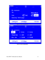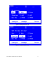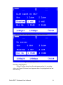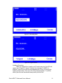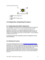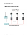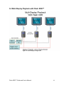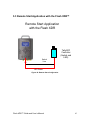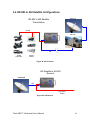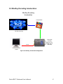
1
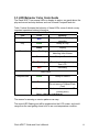
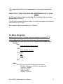
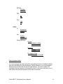
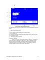
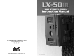
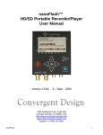
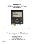
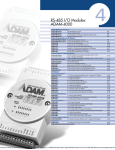
Flash XDR™
Guide and User’s Manual
4465 Northpark Drive, Suite 400
Colorado Springs, CO 80907
http://www.convergent-design.com
[email protected]
Support: 720-221-3861
Toll-Free: 866-654-0080
©2008 Convergent Design, Inc. All Rights Reserved. No part of this publication may be
reproduced, stored in a retrieval system, or transmitted, in any form or by any means,
electronic, mechanical, photocopying, recording or otherwise, without prior written
permission.
Table of Contents
1 Getting Started ................................................................................................................. 4
1.1 Welcome ................................................................................................................... 4
1.2 FCC Compliance....................................................................................................... 4
1.3 Shipping Contents ..................................................................................................... 4
2 Flash XDR™ .................................................................................................................... 5
2.1 Overview ................................................................................................................... 5
2.2 Features ..................................................................................................................... 5
2.3 Functional Block Diagram ........................................................................................ 8
3 Installation and Quick Start ............................................................................................. 9
3.1 Connections............................................................................................................... 9
3.2 User Interface Buttons ............................................................................................ 12
3.3 LED Behavior Color Code Guide ........................................................................... 14
3.4 Menu Navigation .................................................................................................... 15
3.5 LCD Screen Appearance......................................................................................... 20
3.6 CompactFlash Card Guide ...................................................................................... 35
3.7 Basic Workflow ...................................................................................................... 36
3.8 Native Editing in MPEG2: Overview, Facilitation in Final Cut Pro, use with other
NLE's ............................................................................................................................ 37
3.9 Care and Use of the CompactFlash Cards for Flash XDR™.................................. 40
3.10 Power Management .............................................................................................. 40
3.11 User Connector Pin outs ....................................................................................... 41
4 Configuration & Updating Procedure ........................................................................... 42
4.1 Configuration File Editor Application .................................................................... 42
4.2 Updating Procedure ................................................................................................ 42
5 Typical Applications ...................................................................................................... 43
5.1 Multi-Cam Record with the Flash XDR™ ............................................................. 43
5.2 Muti-Display Playback with Flash XDR™ ............................................................ 44
5.3 Remote Start Application with the Flash XDR™................................................... 45
5.4 HD-SDI to ASI Satellite Configurations ................................................................ 46
5.5 Blu-Ray Encoding Acceleration ............................................................................. 47
6 Tips & Troubleshooting ................................................................................................. 48
6.1 Operating Tips ........................................................................................................ 48
6.2 Troubleshooting Guide ........................................................................................... 49
7 Safety & ESD Precautions ............................................................................................. 51
8 Specifications ................................................................................................................. 52
8.1 Inputs....................................................................................................................... 52
8.2 Outputs .................................................................................................................... 53
8.3 CompactFlash ......................................................................................................... 54
Flash XDR™ Guide and User’s Manual
2
8.4 Physical ................................................................................................................... 54
8.5 Power ...................................................................................................................... 54
8.6 Temperature Ranges ............................................................................................... 55
8.7 Humidity ................................................................................................................. 55
9 RMA and Warranty ........................................................................................................ 56
9.1 Conditions of the Warranty..................................................................................... 56
9.2 Obtaining an RMA .................................................................................................. 57
Flash XDR™ Guide and User’s Manual
3
1 Getting Started
1.1 Welcome
Congratulations on selecting Convergent Design HD/SD Portable Recorder,
Flash XDR™. It is shipped from the factory in the most secure packaging
available. Please inspect the contents of the package and make sure to email us
if you find any shipping damage or missing components.
1.2 FCC Compliance
This professional equipment has been tested and found to comply with the
provisions for a Class A digital device under part 15 of the FCC rules. These
provisions are designed to provide reasonable protection against radio-frequency
emissions by digital devices in a commercial environment. This device may
interfere with radio and television reception in residential areas and is required to
accept all interference received, including that which may cause undesired
operation.
1.3 Shipping Contents
Your Flash XDR™ should come packaged with the following:
1) Flash XDR™
2) Power Supply
3) One Transcend 16GB or 32GB CF card (only if paid for as an option)
4) USB Compact Flash Reader w/ USB Cable
5) This User Manual
Flash XDR™ Guide and User’s Manual
4
2 Flash XDR™
2.1 Overview
The Convergent Design Flash XDR™ is a high quality CoactFCompactFlash
based portable video recorder. It implements the use of a full raster 4:2:2 (1920 x
1080) MPEG2 Codec to capture the uncompressed HD-SDI output of many
compatible cameras at bit rates up to 160 Mbps, four to six times that of HDV.
It also features superb 24-bit uncompressed audio.
The Flash XDR™ implements an all solid state, tapeless workflow with the
affordable and widely available CompactFlash media cards, with up to 4 hours of
record time with four 32GB cards at 50 Mbps.
This breakthrough product is camera mountable with several cameras, is low
power, rugged, small in size, and features a rubberized protective jacket.
The Flash XDR™ also featurestime-lapse recording (I-Frame only), a a prerecording buffer, a 24p pull down removal, ,selectableselectable image flip,
audio/video sync adjustment, RAID 1 recording capabilities, and can be triggered
byby an incrementing time code or GPIO.
ASI I/O for microwave uplink and IP connectivity, as well as 4:2:2 10-bit
uncompressed support, are upcoming software updates planned for Spring 2009.
The Flash XDR™ is your key to unlocking the quality potential of your POV,
HDV, XDCAM, or HDCAM cameras, to enjoy the benefits of tapeless workflow.
2.2 Features
1) HD-SDI ↔ (upcoming) 18, 19.7, 25, 35 Mbps 4:2:0 or 160 Mbps 4:2:2,
or (currently) 50, 100 MPEG2 bit rates
Flash XDR™ Guide and User’s Manual
5
2) HD-SDI input (with 8-channel embedded audio and time-code)
a. 1080i @ 59.94/50, 1080p @ 29.97/25/23.98
b. 720p @ 59.94/50
a.
b. 720p @ 60/59.94/50
3) MPEG2 Profiles Supported
a. 422P@HL: 100, 160 Mbps VBR (1920x1080i/p, 1280x720p,
4:2:2, I-Frame Only)
b. 422P@HL: 50, 100 Mbps VBR (1920x1080i/p, 1280x720p,
4:2:2, Long-GOP)
c. MP@HL: 18, 35 Mbps VBR (1440x1080i/p, 4:2:0, Long-GOP)
(XDCAM HD)
d. MP@H-14: 25 Mbps CBR (1440x1080i, 4:2:0, Long-GOP)
(HDV-2)
e. MP@HL: 19.7 Mbps CBR (1280x720p, 4:2:0, Long-GOP)
(HDV-1)
4) Inputs: HD-SDI / ASI (Option), balanced stereo analog audio (XLR) –
switchable between line and microphone levels with 48V phantom
power (mic preamp with 0 to 65dB gain), LTC Timecode Timecode
5) Outputs: 1394 (4-pin: no current operation), HD-SDI (re-clocked) / ASI
(option), balanced stereo analog audio XLR, unbalanced headphone
6) 422/RS-485 communications which can support RS-422 deck control
RS-232/RS-485 communications which can support RS-422 Deck
Control via a commercially available adapter.
7) Audio Input Source: 2-channel analog balanced or 88-channel HD-SDI
embedded
8) Audio Formats:
a. Uncompressed PCM Audio (2/4-channel, 48-kHz, 16/24-bit)
9) Compact: 8” (L) x 6” (W) x 2.5” (D), (203 x 152 x 63 mm), 3 lbs (1.5 kg)
10) Low Power: 10W to 14W to 14W, +6V~+20V DC power, 4-pin XLR;
mounting mounting support for Anton Bauer and IDX batteries
11) Record Start/Stop and Tally Light connector (4-pin Hirose)
Flash XDR™ Guide and User’s Manual
6
12) Rugged, all solid state construction, no disk-drive heads to crash or
tape mechanisms to jam
13) Applications:
a. Upgrade video quality, tapeless work-flow
b. Live-event recording (churches, concerts, etc), news /
courtroom pool feed
c. OB Trucks: ASI to Microwave / Satellite UpLink; digital signage
d. Sports, nature shoots, film documentaries, etc.
e. Helicopters, race cars, airplanes, helmet cameras
f. Medical, corporate, ENG, EFP, underwater cameras
Flash XDR™ Guide and User’s Manual
7
2.3 Functional Block Diagram
Figure 1: Functional Block Diagram
Flash XDR™ Guide and User’s Manual
8
3 Installation and Quick Start
3.1 Connections
Refer to Figures 2, 3, and 4 and the descriptions below when connecting the
Flash XDR™.
Figure 2: Left Side Connections
Figure 3: Right Side Connections
Figure 4: Rear Side Connectors
Flash XDR™ Guide and User’s Manual
9
1) CompactFlash Slots: Insert -solid-state CompactFlash cards for
record and playback.
Note that two of the CompactFlash card slots are oriented differently
than the other two. Carefully insert the CompactFlash cards, two will
appear to be upside-down than the other two.
2) CompactFlash Slot LEDs: Indicator lights for behavior of the cards.
See Section 3.4 for an explanation of LED behavior.
3) Ch. 1-2 Line Out: Analog audio output.
4) Mic/Line Inputs: Analog left and right (Ch.1 and Ch.2) audio inputs.
5) Power: 4-pin XLR DC power in, range +6V to +20V, either from
external battery or included AC adapter.
Caution: If using an AC adapter, be certain to use the supplied unit, or
an adapter specifically approved by Convergent-Design. The use of an
unapproved AC adapter will void your warranty.
Caution: If using an AC adapter, be certain to use the supplied unit, or
an adapter specifically approved by Convergent-Design. The use of
unapproved AC adapters will void your warranty.
6) HP Out: Unbalanced headphone audio output.
7) GPIO/Tally: Tally and GPIO connector for external trigger and tally
light control. Close the switch once for record trigger and once again
for record stop.
8)
9) RS-422/RS-485232/RS-485: For external control of the Flash XDR and
for communications with external devices such as remote controls
and/or laptops.
RS-422 based deck control and time code is support via a
commercially available RS-232 to RS-422 converter, external control of
the Flash XDR™ and for communications with external devices such
as remote controls and/or laptops.
10) On/Off: Momentary pushbutton power button.
Flash XDR™ Guide and User’s Manual
10
(Note formatting changes:)
Pressing this once will perform an ordered shut down.
Press and hold the button for about 6 seconds for an ordered shut
down.
11) LTC In: Linear Time Code input.
12) 1394: 4-pin Firewire connection. Currently performs no operation.
13) SDI Out: SDI only, re-clocked stream with embedded audio and time
code.
14) SDI/ASI Out: SDI and in the future ASI -re-clocked output stream.
15) SDI/ASI In: SDI or ASI video source for recording.
Flash XDR™ Guide and User’s Manual
11
3.2 User Interface Buttons
Refer to Figure 5 below for an explanation of the front panel of the Flash XDR™.
Figure 5: User Interface and LCD Screen
1) LCD Display: Shows the status of the Flash XDR™ in the various
operating modes. Also displays warning and errors in correspondence
with flashing LED error lights.
2) Navigation Buttons: Allows the user to navigate the menu.
Flash XDR™ Guide and User’s Manual
12
3) Function Keys: Programmable function keys for various
configurations. Currently, the only keys that function are <F2> and
<F5>, which can be used for updating and formatting as explained
below. In the future, the user will be able to customize these keys with
the Configuration File editor.
4) Indicator LEDs: Status LEDs for the various play and record modes,
see Section 3.4 for LED behavior codes.
5) Play and Record Buttons: Play, Stop, and Record buttons for control
of the box in the various modes. The Flash XDR™, when powered on,
is in a Setup mode initially. It can also enter Record mode and
Playback mode, the following explains the use of the buttons to
navigate these modes.
a. REC: Press REC to start recording to the card. The unit will
record to CF slot one initially and proceed in order if play time
exceeds the amount needed for one card, allowing the clip to
span several cards. If there is no card present or the card is full,
an error message will appear.
b. STOP: Press once to stop action in either Record or Playback
mode. This may take a few seconds to close the files and get
the unit back into the main operating mode.
c. PLAY: Press once to enter Playback modethe . Currently this
will play back the latest recorded clip on the card from the
beginning. In the future, this will also bring up a list of the clips
on the card that can then be selected to play.
Flash XDR™ Guide and User’s Manual
13
3.3 LED Behavior Color Code Guide
The Flash XDR™ has several LEDs to display its status; one each above the
play and record and stop buttons, and one for each CompactFlash slot.
Table 1 below illustrates the behavior of these LEDs, some of which convey
important operational status information.
Control Top Panel
LED
Color
Meaning
Stop
Blue
Play
Green
Stopped, Off when playing or
recording
Ready to Play
White
Playing
Green Flashing
Not Ready,
detecting video stream
Ready to Record
Record
Green
Recording but with warning,
see LCD
Recording
Red Flashing
Red
Side Panel
CompactFlash
Green
Ready to Record
Red
Recording,
Do not remove CompactFlash
Card
Cards need service, see LCD
(coming soon)
Orange
Table 1: LED Color Code Behavior
The reason for warning or service patterns can vary.
The record LED flashing red will be explained on the LCD screen, and could
range from the card getting close to full to an over-temperature condition..
Flash XDR™ Guide and User’s Manual
14
The CompactFlash LEDs must be checked prior to removing a CompactFlash
card.
WHILE THE CF CARD LED IS SOLID RED, NEVER REMOVE THE CF CARD.
If a CF card is removed during recording, all or a portion of the recording
may be lostIn this future, t
his LED will be orange if the card is nearly full or there have been errors detected
while writing to the CF card.
Both conditions will be presented on the LCD panel
3.4 Menu Navigation
Planned Menu Structure Summary: currently supported for version 0.0.132
(Note to Mike Schell: The red in this section was in the original document)
*To format (erase) CF Crads: Press <F2> and <F5> simultaneously and follow prompts *
System
Date:
Year: Month: Day: Day of Week
Time:
Hour: Minutes: Seconds
File Format:
QT
CDV
About
Video
(Format is auto detected: currently accepted inputs)
NO SRC: indicates no HD-SDI source detected
1080i /50, 1080i/60
720p/50, 720p/60
1080p 30/25/24
1080sf25, 1080sf24
Flash XDR™ Guide and User’s Manual
15
Bit Rate
50 Mbps
100 Mbps
PSF:
In
Out
Play:
Last
All
Audio
In:
Embedded
Analog
Out:
Analog
Headphone
Analog Settings:
Source
Channel 1,2 Line
Channel 1,2 Mic
Phantom
Channel 1,2 On
Channel 1,2 Off
Microphone Gain
Channel 1,2 10-65dB
Menu System Details
You may navigate the menu using the up and down buttons to highlight options
that are selectable with the enter button. Within submenus, you can ascend or
descend menu levels with the left and right buttons. The menu system will
remember the last selection at the previous level of the menu and return you to
that option the next time that level of the menu is opened.
Flash XDR™ Guide and User’s Manual
16
You will note that many of the menu items will will display the currently selected
menu option for your convenience. the currently selected menu option in inverted
background colors for your convenience
Other items displaying values in the inverted selection are action items whose
selection will either toggle a a condition or setting or setting within the system, or
allow you to dial in a new value with the navigation keys. The <The “UP> button
Button” will increase the value, and <the “Down Button”DOWN> will decrease it.
Some menu or action items may be shown on the display with a horizontal line
through the item. This indicates that the item is temporarily unavailable.
This.
This may be themay be the result of another setting in the system or that it
represents an option soon to be added to thethe Flash XDR™ firmwareirmware,
or is an optional feature that is not currently installed in your Flash XDR™, or is
an optional feature that is not currently installed in your Flash XDR.
Main Menu
Besides descending to the submenus, pressing <F2> and <F5> together
while on the main menu will bring up the “Format all Cards” option, see Section
3.5 below for the appearance of the LCD screen in this mode.
System
The “System Menu” described below includes settings likely to remain the same
across multiple sessions of use with the Flash XDR™.
Date
Allows the user to manually dial in day, month, and year data for a particular
videoo shoot.
Time
This option allows the user to either manually enter in the hours, minutes, and
seconds data for a video shoot, or in the future to select the incoming Time Code
(embedded or LTC (External Time code)(External Time code) ) as the preset
time time value.
CF File Format
This option lets the user choose the format of the video stored on the cards.
Flash XDR™ Guide and User’s Manual
17
Future, as s recording optionBy default, the Flash XDR™ in 0.0.132 writes to
Quicktime “.mov” files. An MXF like file format we call “CDV” is also an option
until MXF file support is officially released, which is coming soon.
About
The about option displays basic information about the Flash XDR™. Currently it
features the current firmware version number.
Video
Format Display
This line will display the format of the incoming video stream. As of version
0.0.132, the Flash XDR™ is able to decode all of the formats as seen in Section
8.1 below, but the display will only show certain formats. For example, 1080i at
59.94 and 1080i at 60 will both show up as 1080i60 on the source display. This
also applies to the 1080p24 rates. If no source is present, “NO SRC” is displayed
on this status line.
Bit Rate
This option allows the user to dial in the compression rate of the video being
recorded. As of 0.0.132, the 50 Mb 4:2:2 LG and 100 Mb 4:2:2 LG (Long GOP)
are the preferred format.ining formats.
An Aoptional upgrade is planned to is planned tosupportuncompressed HD-SDI
recordingsHD-SDI recordings.
PSF
This option lets the Flash XDR™ decode formats in the PSF format.
To record psf video in progressive format, on the menu of the Flash XDR choose
Video->PSF->In (checked). If you do not check the box, psf video will be
recorded as interlaced (except for psf 24 frame, which always records as
progressive). See the menu status line to determine exactly how we are
interpreting the video.
To play out progressive video as PSF: choose Video->PSF->Out (checked).
Note about HD-SDI cameras and PSF output:
Sony: All newer Sony cameras with HD-SDI out, when set to 1080p, output
1080psf over HD-SDI.
Flash XDR™ Guide and User’s Manual
18
Thus if you want to record 1080 progressive from Sony to the Flash XDR:
> set Sony output to 1080p
> on the Flash XDR, Video->PSF->In, (checked)
The status line on the Flash XDR should then say "1080sfX", where X is for 24,
25, or 30 when the video is streaming in.
(Some older Sony cameras output 1080p24 as 1080i60 out of HD-SDI, in which
case pulldown removal is required to preserve 24p, coming soon)
Canon XL-H1, XL-H1-S : Canon's "30F" mode and "25F" mode are 1080psf
formats. To record progressive video in these modes:
> set Canon output to 30F or 25F
> on the Flash XDR, Video->PSF->In, (checked)
The status line on the Flash XDR should then say "1080sf .." for 25, or 30 when
the video is streaming in.
Canon's "24F" mode is 1080p24 output as 1080i60. Pulldown removal is
required here to preserve 24p.
Pulldown removal will be added to the Flash XDR as an option in a future
firmware upgrade.
** Note that if you do not check the Video->PSF->In checkbox with a PSF input,
the video is recorded as interlaced.
Play
This menu option allows the user to select which clips to playback when the
<PLAY> button is pressed. Last will play only the last clip recorded on the card.
All, the default, will play all clips on the card from the beginning.
Audio
Source
This menu option allows the user to select which audio source should be
recorded and played out through the SDI out and analog audio out. The audio
source can be selected from the Ch. 1 and Ch. 2 analog audio inputs, or the
embedded audio from the incoming SDI stream.
Out
This menu option lets the user check which outputs they wish to monitor the
audio. Embedded audio over SDI is always running. If the user selects “Analog”,
the 5-pin two channel analog audio output is enabled. If the user selects
“Headphone”, then the 3.5mm unbalanced headphone jack is enabled.
Flash XDR™ Guide and User’s Manual
19
Analog Settings
This menu option lets the user specify more detailed audio settings.
For channels 1 and 2, the user can change whether the input is a Line input or a
Microphone input.
If the input is not a wireless microphone, the user can choose to turn the
phantom power (+48V) on per channel. When this happens, the message “48V to
Mic on ChX?” will appear, and the user will have to confirm twice that they want
phantom power on. NEVER use phantom power on a wireless microphone, as
this will most likely destroy it.
The user can also choose how to adjust the gain with the microphone input, in a
range of 10-65dB.
If the input remains a Line input, then an error message will appear “Line input on
ChX” if the gain or phantom power is attempted to be adjusted. Refer to section
3.5 for the LCD appearance.
3.5 LCD Screen Appearance
The LCD screen will change in appearance depending on which mode the Flash
XDR™ is operating in. Figures 6-23 below show all the current appearances of
LCD. (Note this is not final and only given for the code version 0.0.132)
Basic Appearance
Flash XDR™ Guide and User’s Manual
20
Figure 6: Basic Appearance of the Menu
The following is a description of the various options that appear in Figure 6
above.
1.
2.
3.
4.
5.
6.
Video Format display line
Menu options (white background is selected item)
Error status line
CompactFlash card usage. Status bar shows how full card is per slot
Compression Rate
Time left on card (in minutes)
Submenus: System
Figure 7, 8, 9, and 10 show the submenus “System”. Pressing the
right arrow key will highlight an option as in Figure 8, pressing up and
down will adjust accordingly, and pressing enter will save the setting.
Press left to return to the main list of items. This method of adjusting
settings applies to all the menus in the Flash XDR™.
Flash XDR™ Guide and User’s Manual
21
Figure 7: Appearance of the System submenu
Figure 8: Adjusting the Date Options
Flash XDR™ Guide and User’s Manual
22
Figure 9: Adjusting the File Format option
Figure 10: About Menu Appearance
Submenus: Video
Figure 11 shows the options for the Video submenu, showing that
in this example, the Bit Rate has been selected to be 100 Mbps. Figure 12
shows the PSF selection options, a check will appear in these boxes as
shown. Figure 13 shows the Play section option.
Flash XDR™ Guide and User’s Manual
23
Figure 11: Changing the Bit Rate in the Video Submenu
Figure 12: Selecting PSF options
Flash XDR™ Guide and User’s Manual
24
Figure 13: Adjusting the Play option
Submenu: Audio
Figure 14 features the appearance of the Audio submenu. The In
options are Analog and Embedded. Figure 15 shows the adjustment of the
output settings. Figure 16 shows the Analog Settings option. Figure 17
shows the adjustment of the type of input (Line, Mic). Figure 18 shows
turning on the phantom power, with the confirmation message. Figure 19
shows the message when phantom power is attempted to be applied to a
Line input. Figure 20 shows the adjustment of the gain.
Figure 14: Audio submenu
Flash XDR™ Guide and User’s Manual
25
Figure 15: Audio Output Options
Figure 16: Audio Settings Menu
Flash XDR™ Guide and User’s Manual
26
Figure 17: Adjusting the Source Type
Figure 18: Turning on Phantom Power
Flash XDR™ Guide and User’s Manual
27
Figure 19: Error when adjusting Phantom or Gain with Line Input
Figure 20: Adjusting the Gain
Recording and Playback
Figure 21 below shows how the unit appears when it is recording
video, and Figure 22 shows how it appears when it is playing back the last
recorded clip.
Flash XDR™ Guide and User’s Manual
28
Figure 21: Recording Mode
Figure 22: Playback Mode
Updating Procedure
When an update file is found on a CF card in any slot, the LCD will
appear as in Figure 23. Figure 24 shows the message if <STOP> is
pressed. Figure 25 and 26 show the appearances of the LCD during the
update process when <F2> and <F5> are pressed together. To exit this
mode, eject the card as directed and power cycle the unit.
Flash XDR™ Guide and User’s Manual
29
Figure 23: When an update card is present
Figure 24: Message when update procedure aborted
Flash XDR™ Guide and User’s Manual
30
Figure 25: Update Procedure: first the current code is erased
Figure 26: Update Procedure:
Flash XDR™ Guide and User’s Manual
31
Formatting CompactFlash cards
Pressing <F2> and <F5> while in the main menu will bring up the
options for Formatting all of the cards present in the Flash XDR™ , and
will appear as in Figure 27. Figure 28 shows the message of a completed
format before returning to the main menu, and Figure 29 shows the
message when this format procedure is aborted. When a format is
aborted, the user must remove all cards before it returns to the main
menu.
Figure 27: Formatting Options Display
Flash XDR™ Guide and User’s Manual
32
Figure 28: Format Completed Message
Figure 29: Format Aborted Message
Flash XDR™ Guide and User’s Manual
33
Error Messages
Figure 30 and 31 show two of many error messages that may
appear when operating the unit. If the box is recording video and the
record button is pressed again, a message like Figure 30 will appear. If
there is no video source and the record button is pressed, a message like
Figure 31 will appear. Similar messages will appear for other modes, such
as “Already Playing”, “No Space on Card”, “No clips on Card”, “Already
Stopping”, and “Unknown CFX”. See the troubleshoot guide, Section 6.2,
for a complete list of what will trigger these messages.
Figure 30: Error message when record button is pressed twice
Flash XDR™ Guide and User’s Manual
34
Figure 31: Error message when record button is pressed and no video input
3.6 CompactFlash Card Guide
Research and tests have proved that the best CompactFlash cards for the Flash
XDR™ are the Transcend 16GB 300x and 32GB 133x.
The 32GB card is widely available for around $82, while the 16GB cards are
starting to hit the market at $165. On a GB basis, the 32GB card is 1/10 the cost
of other professional solid state media. CF speed ratings are based on the old
audio CD rate of 1x= 150 Kbytes/sec, so 133x = 20 Mbytes/sec (or 160 Mbps)
and 300x = 45 Mbytes/sec (or 360 Mbps). It should be noted that this number
refers to the read speed and not necessarily the write speed, which is lower.
Both of these cards employ UDMA read and write transfer protocol. The 32GB
card employs UDMA-4, while the 16GB card employs the newer UDMA-5. UDMA
enables long burst transfers of up to 128 Kbytes without host intervention. Since
all video and audio transfers are done by hardware in the Flash XDR™, there are
no dropped frames and it is at its fastest possible performance.
As data is written (or read) to the CF card, and 16-bit CRC (cyclic redundancy
check) is generated every 512 bytes by both the Flash XDR™ and the
CompactFlash card. The two CRCs are continuously compared to ensure reliable
data transfers. Any errors will trigger a warning in recording and be displayed on
the LCD screen.
Table 2 below shows the approximate record times possible for a single card and
four cards.
Flash XDR™ Guide and User’s Manual
35
Compression
Record Time, 32GB,
Single Card (Mins)
Record Time, 32GB,
Four Cards (Mins)
Record Time, 16GB,
Single Card (Mins)
Record Time, 16GB,
Four Cards (Mins)
50Mbps
71
100Mbps
36
284
142
36
18
142
71
Table 2: Approximate Record Times for Transcend CF Cards
3.7 Basic Workflow
Figure 32 below illustrates the basic workflow for capture of encoded video to an
NLE system. It is recommended that the user employ a Firewire 800 (1394B)
connection for optimum speed of write and capture. The Lexar Firewire 800
stacked CF port units are the best choice. Newer PCs have 1394B standard. The
user can use a Belkin Express Card port to upgrade a laptop connection. All
Mac’s have 1394B standardized already, so those users need not upgrade.
Flash XDR™ Guide and User’s Manual
36
Typical Workflow For NLE Capture
HD-SDI Video
Source
Recorded Video on
CompactFlash
1394B
Lexar Firewire 800
or similar CF
Reader
NLE
Figure 32: Typical Workflow
3.8 Native Editing in MPEG2: Overview, Facilitation in
Final Cut Pro, use with other NLE's
In Final Cut Pro you can now minimize the lengthy render times associated with
native MPEG2 long GOP editing.
Flash XDR™ Guide and User’s Manual
37
MPEG2: A simple Primer
Some common types of MPEG2 long GOP compression include:
-HDV (18 to 25 Mbits / sec data rate, 4:2:0 colorspace, 1440x1080 compressed
resolution for 1920x1080 1080i/p)
-XDCAM EX (35 Mbits / sec, 4:2:0 colorspace, 1440x1080 or 1920x1080 for
1080i/p)
-XDCAM HD 422 (typically 50 Mbits / sec to 100 Mbits / sec, 4:2:2 colorspace,
1920x1080 compressed resolution for 1080i/p)
For comparison, uncompressed HD 4:2:2 is 1,000 to 1,200 Mbits / sec.
Most I-Frame codecs are 100 to 220 Mbits / sec in HD.
The distinctive feature of MPEG2 long GOP compression, when compared to IFrame compression, is that video frames are compressed temporally as well as
spatially.
The I-Frame codecs (DVC Pro, Cineform, ProRes, etc) use only spatial
compression, meaning that each frame is compressed individually and can be
reconstructed individually.
With MPEG2, frames are organized into GOP's (group of pictures), typically 12 or
15 frames. Within a GOP, video information is shared, so that information that is
repeated from 1 frame to the next (such as a background that does not change)
is stored once within the GOP instead of being stored in each individual frame.
So MPEG2 uses temporal compression as well, meaning a particular frame will
depend on other frames (other points in time) to be compressed and
decompressed.
The major advantage of MPEG2 is greater efficiency of compression, meaning
better quality at lower bit rates.
The major disadvantage is the difficulty of editing MPEG2, because the more
complex encoding scheme induces lengthy render times when editing MPEG2
natively and preparing a sequence for output. Reconstructing the long GOP
video during the rendering process is typically a time consuming process.
Editing Flash XDR Quicktime files natively, avoiding lengthy render
The Flash XDR (and nanoFlash, when it becomes available) supports 50 and
100 Mbit, XDCAM HD 4:2:2 MPEG2 long GOP compression, (and will likely
support MPEG2 at lower bit rates in the future).
Flash XDR™ Guide and User’s Manual
38
Final Cut Pro (since version 6.0.2) supports native XDCAM HD 4:2:2 editing for
50 Mbit.
Final Cut Pro now has a shortcut to help minimize rendering when editing
MPEG2 natively. Here are the steps to achieve this with XDCAM HD 422
footage:
1. Set up a sequence / timeline as XDCAM HD 422
2. In Final Cut Pro (6.0.2 or greater) -> User Preferences -> Render Control, set
the codec to ProRes
3. Drop your 50 Mbit Quicktime clips directly into the timeline (you do not need to
transcode first) for editing
What this does is render the effects in your sequence to an I-Frame codec
(ProRes), and areas of the timeline which do not have effects applied are left
alone. Your sequence is not encoded back to MPEG2 long GOP.
Because I-Frame encoding is faster than long GOP encoding, and because only
the areas of the timeline with effects are rendered (re-encoded) to an I-Frame
codec, this is where the time savings comes into play.
Note that if you place your MPEG2 footage directly into a ProRes or other IFrame timeline, when you are ready to play out your sequence the MPEG2 will
be transcoded to the I-Frame codec first; that is, it will be decompressed and
recompressed to the I-Frame codec. Certainly this is a viable option but it will add
considerable time to the whole process.
(However if you choose "Render Selection" as opposed to "Render All" a
transcode of the MPEG2 is probably avoided as the default behavior, but this
approach is a bit messier and potentially error prone.)
Editing MPEG2 with other NLE's
Flash XDR / nanoFlash will additionally support the MXF file format, which is
accepted by most other NLE's.
Native editing in MPEG2 with any NLE is possible, provided that your NLE
supports the XDCAM HD 422 profile. Note that NLE's which support this profile,
however, will typically render / re-encode the video at the 50 Mbit data rate only,
for play out. (And rendering MPEG2 video can take a while. )
Alternatively you can transcode all of your MPEG2 footage to an I-Frame codec
in advance, which is a way to avoid native MPEG2 editing altogether.
Transcoding, however, can also be time consuming and creates an additional
decompression/compression cycle for the video.
Flash XDR™ Guide and User’s Manual
39
3.9 Care and Use of the CompactFlash Cards for Flash
XDR™
There are several important steps to follow when handling CompactFlash cards
for the unit.
1. Use of a special CompactFlash card ONLY for updating and configuration
files, explained below in section 4.
2. NEVER remove the card while it is being recorded to (indicator LED solid
red)
3. Treat the card as READ ONLY outside of the Flash XDR™. DO NOT
defragment, change the file structure or file names, change
directories, or add personal files to any card used by the Flash
XDR™.
4. Cards from the factory come formatted. When the user has successfully
copied the written video files to the NLE, format the card with the PC or
Mac or onboard the Flash XDR™ before reusing the card.
5. Never force the card into the CompactFlash slot. Cocking the card or
forcing it in could damage the contact pins and render the slot useless.
6. Only the Transcend 16GB or 32GB cards are tested and approved for use
at this time.
3.10 Power Management
When operating the Flash XDR™ in portable environments with an attached
battery, it is important to practice good power management.
1.
Audio output can be controlled completely independent of Audio
Input, and it is advised to disable it when not in use.
2.
Mic1 and Mic2 power should be off whenever possible due to it
being +48V powering line microphones.
3.
The LCD screen backlight can be reduced in intensity to save
some power.
4.
The Flash XDR™ features a power standby mode by pressing
the power button once to shut down the unit. Power consumption
is minimal at this level.
Flash XDR™ Guide and User’s Manual
40
3.11 User Connector Pin outs
Certain connectors on the Flash XDR have pin outs that the user may have to
adapt to, depending on the equipment being interfaced. Below are the three most
important connectors to pay attention to, since they may not be standard for your
application. These are the pin outs that the Flash XDR™ features.
4-pin XLR Power
Figure 33: 4-pin power pin out
1.
2.
3.
4.
Ground connection
NC: no connect
NC: no connect
PWR: +6.5~+20V power connection, “hot” side
5-pin Audio XLR Connector
Figure 34: 5-pin audio connector pin out
1.
2.
3.
4.
5.
GND: Signal ground
L+: Left channel positive
L-: Left channel negative
R+: Right channel positive
R-: Right channel negative
Flash XDR™ Guide and User’s Manual
41
4-pin Hirose GPIO Connector
Figure 35: 4-pin Hirose pin out
1.
2.
3.
4.
START: Record trigger input
GND
TALLY LED: Tally light power
GND
4 Configuration & Updating Procedure
4.1 Configuration File Editor Application
The Configuration File Editor will act as a computer based method to change the
various settings in the menu. Thus, the user can either make the changes
onboard the Flash XDR™, or the user can make all the changes in this
application, and save them as a particular configuration file. The app takes the
configuration file and puts it into a directory that the Flash XDR™ can load the
file from in the “Save/Recall” menu option. The Flash XDR™ can load 8 separate
configuration files at a time.
As of version 0.0.132, this configuration method is unsupported, more to
come in the future.
4.2 Updating Procedure
The current updating procedure is to go to http://www.convergent-design.com,
proceeding to download the firmware update file from the front page. The update
file will come in a .zip format, simply extract this zip to a directory. In this file set
there will be some user guide .pdf’s, and a folder called “}UPD{“. Copy that folder
only directly onto a new CompactFlash card, and the Flash XDR™ will
automatically detect the update. Refer to Section 3.5 above for the LCD screen
appearance for this update procedure. In the future, a specific update application
that automatically finds the files and writes them to the card will be available for
download.
Flash XDR™ Guide and User’s Manual
42
5 Typical Applications
5.1 Multi-Cam Record with the Flash XDR™
Figure 36: Mutli-Cam Record Configuration
Flash XDR™ Guide and User’s Manual
43
5.2 Muti-Display Playback with Flash XDR™
Figure 37: Muti-Display Configuration
Flash XDR™ Guide and User’s Manual
44
5.3 Remote Start Application with the Flash XDR™
Remote Start Application
with the Flash XDR
Tally/GPI
Controller
(Switch and
LED)
Switch
Line
LED Power
Figure 38: Remote Start Configuration
Flash XDR™ Guide and User’s Manual
45
5.4 HD-SDI to ASI Satellite Configurations
Satellite TX
HD-SDI to ASI Satellite
Transmission
HD-SDI
OB Truck
ASI
HD-SDI
Camcorders
HD POV
Cameras
Figure 39: ASI Transmit
ASI Satellite to HD-SDI
Receive
Satellite RX
ASI
HD-SDI to
Studio
Figure 40: ASI Receive
Flash XDR™ Guide and User’s Manual
46
5.5 Blu-Ray Encoding Acceleration
Blu-Ray Encoding
Acceleration
CompactFlash
Blu-Ray Authoring
HD-SDI
Flash XDR
encoding
MPEG2 4:2:0,
18Mbps @ 1X
(real time)
NLE with finished
project
Figure 41: Blu-Ray Accelerated Configuration
Flash XDR™ Guide and User’s Manual
47
6 Tips & Troubleshooting
6.1 Operating Tips
1. Never pull the CompactFlash card out while recording: The most critical
error a user can cause is pulling out the CompactFlash card prematurely.
The file structure needs special instructions from the microcontroller to
properly close the files for them to be read properly. The use of the power
button allows the Flash XDR™ to stop its current operations, close all
files, and properly “shut down”. Pulling out the card while recording will
almost certainly cause total loss of the current file being recorded on the
card. Cards that are being written to will have a solid red LED next to
them, and instructions for the CompactFlash slots are silk-screened above
them on the box.
2. Avoiding Overheating the Flash XDR™: The unit will perform an automatic
shut down if it becomes overheated. The best way to avoid overheating is
to keep the unit out of the sunlight, as the rubber over-mold and finish on
the box is black. See section 8 below for the operating temperature range.
3. Equipment warm-up Time: Turn on deck/camera and Flash XDR™ for at
least 5 minutes prior to use. This lets the crystal oscillators inside the
camera/deck and Flash XDR™ warm up and stabilize in frequency.
4. Continuous Timecode and Leaders in Video Capture. For purposes of
searching in the course of a batch capture, it is best to have a clip without
timecode breaks. A camera in free-run timecode mode will continue to
advance its internal timecode while the camera is not recording. This can
create significant gaps in timecode from one clip recording to the next and
may cause problems in later searches. Even greater problems arise when
there are multiple instances of the same timecode in a single run. For
best results, the camera should be set in record-run mode with a desired
starting timecode and the timecode not reset until the full clip has been
recorded. This should cause the camera to begin advancing its internal
timecode only each time the record button is pushed. It is also
recommended that the first clip recorded have a leader of 30 seconds or
more of sacrificial material in order to prevent a reverse search from
overrunning the timecodes on the clips. There should also be a leader
before each subsequent scene at least as long as the preroll during batch
capture. The recommended preroll time for a batch capture is 6 seconds
5. Only use recommended CompactFlash cards: Use only the Transcend
16GB or 32GB cards, otherwise it is not guaranteed that the Flash XDR™
will operate at specified performance.
Flash XDR™ Guide and User’s Manual
48
6. CF Card Monitoring: Each card slot has a progress bar at the top of the
LCD screen, see Section 3.5 for details. The total record time remaining in
minutes is always displayed on the status line on the right side.
7. CF Card Erase/Formatting Procedure: To format or erase all cards
inserted into the unit, press <F2> and <F5> at the same time and follow
prompts.
6.2 Troubleshooting Guide
1. No Video Output over SDI
a. Plug the HD-SDI source directly into an HD-SDI monitor to make
sure video is flowing
b. Set the box to output color bars (when available)
c. If you are trying to connect to an SDI monitor and the output is HDSDI, is the monitor HD capable or is it limited to SD?
2. No function of the Flash XDR™
a. Check that the unit is powered on with the proper power adapter
b. Make sure the unit is not in standby mode
3. An error message appears
a. Message “Already Recording” appears if the <RECORD> button
is pressed twice.
b. Message “Already Playing” appears if the <PLAY> button is
pressed twice.
c. Message “No space on card” appears if the card (or cards) in the
unit are full, or if the <RECORD> button is pressed and no cards
are present.
d. Message “No clips on card” appears if the <PLAY> button is
pressed on an empty card.
e. Message “Already Stopping” appears if the <STOP> button is
pressed while the unit is closing the files after the first press of
<STOP>.
f. Message “No valid source” appears when the <RECORD> is
pressed while the unit is not plugged into a video source.
g. Message “Unknown CFX”, where X refers to slots 1-4, appears if
a brand new card needs to be formatted and cannot be recorded to.
h. Message “Lost Input” and “Closing Clip” will appear if the video
source is unconnected while recording. This is a fatal error that will
cause the box to crash and the current recorded clip to be lost.
i. Message “Busy Playing” appears if the <RECORD> or Tally
control input is asserted while the unit is playing a clip.
j. Message “Still Playing” appears if the <RECORD> button is
pressed while the unit is closing a clip, at the end of a playing of a
clip.
Flash XDR™ Guide and User’s Manual
49
k. Message “Busy Recording” appears if the <PLAY> button is
pressed while the unit is recoding.
l. Message “No Last Clip” appears if the “Last” option is selected in
the “Play” menu and there is no last clip the unit can play since
power on.
m. The following messages are fatal errors, and if any are encountered
the user should call the tech support line immediately. The best
solution currently is to power cycle the box.
i. ID CF Dev
ii. ATA Idle
iii. Wrcache
iv. UDMA4
v. SlotDpc
vi. DMA WR
vii. DMA RD
viii. DMA WR Q
‘
Flash XDR™ Guide and User’s Manual
50
7 Safety & ESD Precautions
1. Always connect the box to the specified power source: +6 to 20 V DC. DO
NOT use any power supply other than the one supplied with the Flash
XDR™ or an approved battery, as this will void the warranty.
2. Avoid operating the unit in an unprotected outdoor installation or wet
areas. Do not expose this product to rain, sand, or snow.
3. Keep the CompactFlash slot rubber protector on as much as possible.
Avoid servicing the cards while the unit is in an adverse environment.
4. Take caution when connecting the 1394 plug. The 4-pin connector on the
Flash XDR™, connected with a 6-pin end to a PC or Mac, can still cause
damage to the internal 1394 circuitry if it is cocked when plugged in.
5. Keep the operating temperature between 5º C and 40º C (40º F and 104º
F). Avoid conditions which would cause moisture condensation on the
outside cover.
6. Do not drop the unit as this will cause significant damage to several
components. Damage due to dropped units is not covered by the
warranty.
7. There are no user serviceable components inside the box. Only a qualified
technician should perform servicing of the unit. Opening the box may void
the warranty.
8. Do not pour water or any other fluid over the box. Avoid the use of sharp
objects near the box as they may scratch the LCD or cut into the rubber
over-molding.
9. Clean only with water with a damp cloth.
10. CAUTION: Electrostatic Discharge (ESD) can damage components in this
product. Although the unit has countermeasures to this hazard installed
inside, it is always best to avoid damage by using extra caution when
handling and inserting CompactFlash cards or the LCD screen and
connectors. Always ground yourself (by touching an un-painted grounded
metal object) prior to handling the unit.
11. Do not touch exposed connector pins and do not insert any metal objects
in the connectors.
12. Ensure that all connections made to the box (including at the “other end of
the cable”) are made in ESD safe environments.
13. Always transport and store the box in the static protected bag included
with the Flash XDR™
14. Never connect a wireless microphone to the Flash XDR™ while the +48V
Phantom Power is turned on, as this will most likely result in the
destruction of your microphone.
15. Use caution when connecting the 4-pin XLR power, 5-pin XLR audio, and
4-pin Hirose GPIO ports, as the pinouts for these types of connectors is
not always standard across all toolsets. The pinout that the Flash XDR™
uses is detailed in Section 3.11 above, use this as a guide to ensure that
proper connections are being made and damage is not done to your unit
as a result of improper connections.
Flash XDR™ Guide and User’s Manual
51
8 Specifications
8.1 Inputs
HD-SDI/ASI
Formats:
• 1920x1080i, 60Hz
• 1920x1080i, 59.94Hz
• 1920x1080i, 50Hz
• 1920x1080p, 30Hz
• 1920x1080psf, 30Hz, de-interlaced
• 1920x1080p, 29.97Hz
• 1920x1080p, 25Hz
• 1920x1080psf, 25Hz, de-interlaced
• 1920x1080p, 24Hz
• 1920x1080psf, 24Hz, de-interlaced
• 1920x1080p, 23.98Hz
• 1280x720p, 60Hz
• 1280x720p, 59.94Hz
• 1280x720p, 50Hz
Standards:
• SMPTE 274M (1080i), 296M (720p)
• SMPTE High Def Color Bars RP-219
• 4 Channel Embedded Audio
• Audio: 24-bit, 48kHz, SMPTE 299M
Connector: 75Ω BNC
Analog Audio
Format:
• 24 bit A/D, 2 channels, 48kHz
• Swtichable between line and microphone level w/ 48V phantom power
• Mic Pre-amp with 10 to 65 dB gain
Connectors: 3-pin and 5-pin XLR
Linear Time Code
Standards:
• SMPTE RP-188 (HD)
• HD 1080i Lines: 14, 16, 577, 579
Connector: 75Ω BNC
Flash XDR™ Guide and User’s Manual
52
8.2 Outputs
HD-SDI/ASI
Standards & Formats:
• Same as for Inputs above
HD-SDI Performance:
• Rise Time = 160 pS
• Fall Time = 140 pS
• Amplitude = 750mV
• Alignment Jitter (100 kHz) = 110 pS
• Jitter (10 kHz) = 138 pS
• Jitter (1 kHz) = 138 pS
• Timing Jitter (10 Hz) = 180 pS
Connector: 75Ω BNC
Embedded Time Code
Standards:
• SMPTE RP-188 (HD)
• HD 1080i Lines: 14, 16, 577, 579
Connector: 75Ω BNC
1394
• Currently no operation
Analog Unbalanced Audio (Headphone)
Standards:
• Level: 1 Vp-p
Connector: 3.5 mm Stereo Plug
Balanced Stereo Analog Audio
Formats:
• MPEG1 Layer 2 (384 Kbps: 2-Channel, 192 Kbps: 4-Channel)
• Uncompressed PCM Audio (2/4-Channel, 48 KHz, 16 or 24 bit)
Connector: 5-pin XLR (combined Channels 1 & 2)
Flash XDR™ Guide and User’s Manual
53
8.3 CompactFlash
MPEG2 Profiles Supported:
• 422P@HL: 100 or 160 Mbps VBR, 1920x1080i, 4:2:2 I-Frame Only
• 422P@HL: 100 or 160 Mbps VBR, 1920x1080p, 4:2:2 I-Frame Only
• 422P@HL: 100 or 160 Mbps VBR, 1280x720p, 4:2:2 I-Frame Only
• 422P@HL: 50 or 100 Mbps VBR, 1920x1080i, 4:2:2 Long GOP
• 422P@HL: 50 or 100 Mbps VBR, 1920x1080p, 4:2:2 Long GOP
• 422P@HL: 50 or 100 Mbps VBR, 1280x720p, 4:2:2 Long GOP
• MP@HL: 18 or 25 Mbps VBR, 1440x1080i, 4:2:0, Long GOP (XDCAM)
• MP@HL: 18 or 25 Mbps VBR, 1440x1080p, 4:2:0, Long GOP
• MP@H-14: 25 Mbps CBR, 1440x1080i, 4:2:0, Long GOP, HDV2
• MP@HL: 19.7 Mbps CBR, 1280x720p, 4:2:0, Long GOP, HDV1
Formats:
• Quicktime .mov
• MXF
8.4 Physical
Dimensions
• 8” (203 mm) deep x 6”(152 mm) wide x 2.5” (63 mm) high
Weight
• 3 lbs (1.5 kg)
8.5 Power
Range
• Unit Input Power: +6 to 20V, 4-Pin XLR connector
• Support for Anton Bauer and IDX Batteries
Maximum Operating
• 13W to 16W
Flash XDR™ Guide and User’s Manual
54
8.6 Temperature Ranges
Operating
• 40º F to 104º F (5º C to 40º C)
Storage
• -5ºF to 140ºF (-20º C to 60º C)
8.7 Humidity
Operating
• Less than 80% (non-condensing)
Storage
• Less than 90% (non-condensing)
Flash XDR™ Guide and User’s Manual
55
9 RMA and Warranty
9.1 Conditions of the Warranty
Convergent Design reserves the right to determine if a repair is subject to the
warranty agreement. Damages caused by products being dropped or mishandled
are not covered by this warranty. Also damage caused by over-voltage
conditions on any of the I/O connectors is not covered by this warranty. Use of
any power supply other than the one provided automatically voids the warranty.
There are no user-serviceable parts inside the cabinet. Opening the cabinet
voids the warranty. Transit damage caused by inadequate packaging also
invalidates the warranty agreement. Please ship the unit in its original packaging,
if possible.
All products are shipped prepaid to Convergent Design. For insurance reasons,
Convergent Design cannot accept any product that is returned via U.S. Postal
Service. Returns will be accepted from Federal Express, UPS, DHL, or other
comparable freight carrier. Convergent Design returns the product via a prepaid
two-day delivery service within the continental United States, only if the product
is under warranty and subsequently found to be faulty. Out-of-warranty repaired
products are shipped at customer’s expense. Turnaround time for warranty
repairs normally will not exceed 48 hours (excluding shipping time), unless
extraordinary fault conditions exist. A failure analysis report is returned with each
product.
Labor and defects are covered for the warranty period stated on your original
invoice from the original date of purchase. Only the original purchaser of the
products is covered under this warranty. The warranty is non-transferable. If you
discover a defect, please refer to our Return Merchandise Policy below. The
warranty covers all Convergent Design hardware defective in material or
workmanship. Software is warranted in a separate written statement
accompanying the software. During the warranty period, Convergent Design, at
its option, will repair or replace product or product components, which in its
opinion prove defective. Parts and components used in the repair process may
be recycled or repaired, at Convergent Design’s discretion. This warranty service
will be performed at no charge to the registered owner, provided the product is
shipped prepaid to Convergent Design. Convergent Design will return the
repaired product via a like carrier, in the continental United States within 48
hours, shipping time excluded. Convergent Design reserves the right to
determine whether a needed repair is subject to the warranty as per its
provisions sated herein. Transit damage caused by inadequate packing violates
the warranty. The warranty will be void if, in the opinion of Convergent Design,
the product has been damages through accident, misuse, misapplication, or as a
Flash XDR™ Guide and User’s Manual
56
result of service or modification performed not authorized in writing by
Convergent Design.
WARNING: The following are not covered under warranty:
•
Damage due to the use of a power supply other than that supplied with
Flash XDR™ or un-certified batteries.
•
Damage caused by improper connections to external 1394 devices
supplying power over the 1394 cable.
9.2 Obtaining an RMA
It is our policy that all material and repair returns, whether in warranty or not, are
only accepted if an RMA (Return Merchandise Authorization) number has been
issued for the products being returned. Any unauthorized shipments will be
returned, un-repaired at the customer’s expense.
Damaged or defective Convergent Design products that are purchased from
Convergent Design may be returned for replacement only. Convergent Design
will not accept returns for any other reason. All eligible returns require a Return
Merchandise Authorization (RMA) number. E-mail Convergent Design, Inc. at
[email protected] to obtain an RMA number. Items must be
returned within 10 days of receiving your RMA number. Returned product must
be in its original packaging with all contents included and must have the RMA
number clearly marked on the outside of the package.
RMA numbers and return address may be obtained from Technical Support.
Convergent Design, Inc.
4465 Northpark Drive
Suite 201
Colorado Springs, CO 80907
EMAIL: [email protected]
WEBSITE: http://www.convergent-design.com
VOICE: (720) 221-3861 or (866) 654-0080
Flash XDR™ Guide and User’s Manual
57
Flash XDR™ Guide and User’s Manual
58