1
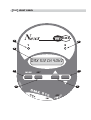
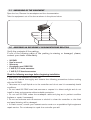
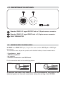
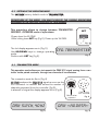
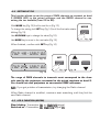
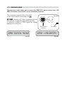
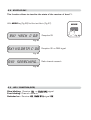
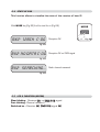
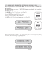
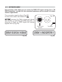
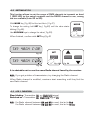
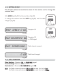
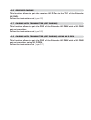
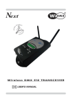
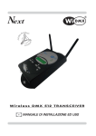
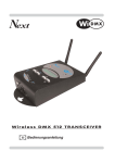
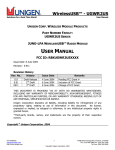
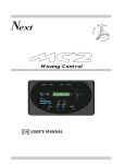
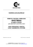
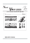
Next
Wi D M X
Wireless DMX 512 TRANSCEIVER
GB
USER’S MANUAL
We congratulate you on your purchase of Wi DMX.
Before you proced using this product it should be necessary to read carefully the following user’s manual to install it correctly and to get the best of
its potentialities.
GB
fRONT PANEL
Next
1
Wi D M X
2
1
2
3
DMX 512 ch 40hZ
4
MODE
6
SET
9VDC
7
IN
5
DM
OU
T
X 5
12
IN
M.
TER OFF
ON
1
Shows the state of transmission/receipt of the channel 1
2
Shows the state of transmission/receipt of the channel 2
3
LCD display, it shows all the informations on the Wi DMX functions.
4
MODE key
5
SET key
6
DOWN key
7
UP key
INDEX
Setting of the equipment
1.1 Unpacking of the equipment
1.2 Acessories issued with the equipment and relative documentation
Description of the side panel and installation
2.1
2.2
2.3
2.4
Description of the side panel
Making a DMX 512 signal cable
Input connection for power supply
Connection of the ac-adapter to the electric system
Initial setting
3.1 Setting of the operating mode
Use of the equipment - operating modes
4.1
4.2
4.3
4.4
4.5
4.6
TRANSMITTER mode
Setting of Tx1
LED 1 function
Setting of Tx2
LED 2 function
Receiver PAIRING
5.1
5.2
5.3
5.4
5.5
5.6
5.7
RECEIVER mode
State of Rx1
LED 1 function
State of Rx2
LED 2 function
Pairing with Transmitter (GET PAIRING)
Pairing with Transmitter (GET PAIRING) using Wi D PEN
6.1
6.2
6.3
6.4
6.5
6.6
6.7
6.8
EXTENDER mode
Setting of Tx1
LED 1 function
Setting of Rx2
LED 2 function
Receiver PAIRING
Pairing with Transmitter (GET PAIRING)
Pairing with Transmitter (GET PAIRING) using Wi D PEN
1.1
UNPACKING OF THE EQUIPMENT
Open the box; Remove the ac-adapter and the documentation.
Take the equipment out of the box as shown in the picture below.
1.2
ACCESSORI IN DOTAZIONE E DOCUMENTAZIONE RELATIVA
Verify the contents of the packing.
If one of the following parts of the packing is missing or damaged, please,
contact your dealer immediately.
•
•
•
•
•
•
Wi DMX
User’s manual.
Warranty
Ac-adapter mod.1882108
1 XLR 3/5 P male connector
1 XLR 3/5 P female connector
Read the following warnings before beginning installation.
• This unit is not intended for home use.
• Read this manual thoroughly and observe the following precautions before working
with the Wi DMX.
• Take care not to spill liquids on to the controller and do not use it in excessively humid
conditions.
• Do not install Wi DMX near heat sources or expose it to direct sunlight and do not
install in dusty environments without suitable protection.
• Do not use Wi DMX unless the ac-adapter cable and plug are in perfect condition
(replace or repair if necessary).
• Do not use solvents such as acetone or alcohol to clean the controller or the finish
and panel lettering will be damaged.
• If a fault occurs, consult your nearest service centre or a specialized light equipment
repair service. Do not attempt to repair the controller yourself.
2.1
DESCRIPTION OF THE SIDE PANEL
1
2
5
1
5
1
4
2
4
2
3
3
3
1
Standard DMX 512 signal OUTPUT with a 3/5-pole cannon connector.
2
Standard DMX 512 signal INPUT with a 3/5-pole cannon connector.
3
DMX TERMINATOR
2.2
MAKING A DMX 512 SIGNAL CABLE
Wi DMX has a DMX 512 input/output that uses standard XLR 5-pin or XLR 3-pin
connectors.
The connection must be put into practice with shielded cable by these characteristics:
-
2 conductors + shield
120 Ohm impedance
low capacity
maximum transmission rate 250 Kbaud.
For the connection refer to the underlying picture
XLR 5-pin
XLR 3-pin
5
1
4
2
3
Common
DMX DMX +
2
1
3
Common
DMX DMX +
ATTENTION: the shield of the cable must never be connected to the ground of the
electrical system as this could cause faults during the working of the Wi DMX.
2.3
INPUT CONNECTION FOR POWER SUPPLY
4
Plug the connector of the ac-adapter completly in the power input
To disconnect it, extract gently.
4
ATTENTION: do not use ac-adapters different from the one supplied, it
could cause serious damages at the internal circuitation.
2.4
CONNECTION OF THE AC-ADAPTER TO THE ELECTRIC SYSTEM
MAKE SURE THAT VOLTAGE AND POWER FREQUENCY CORRESPOND TO
WHAT IS REPORTED ON THE BALLAST PLATE.
The supplied ac-adapter has a plug, therefore you should only plug it in the
socket.
When Wi DMX is powered, the lcd display
appears as in (Fig.1),if this condition is not
true, please check if there is power in the
electric socket or check the connection
between ac-adapter/controller and ac-adapter/electric socket.
If the problem persist, please consult your dealer.
Next
WIRELESS
Fig. 1
3.1
SETTING OF THE OPERATING MODE
The Wi DMX factory default mode is TRANSMITTER
REGARDLESS OF THE MODE, YOU MUST EXECUTE THE PAIRING OPERATIONS
EXPLAINED IN THE RELATIVE CHAPTERS OF THIS MANUAL
This procedure allows to change between TRANSMITTER RECEIVER - EXTENDER mode of operationa.
SET
-Power down the Wi DMX.
-While holding down SET key (Fig.2), Power up the Wi DMX.
Fig. 2
The lcd display appears as in (Fig.3).
Use UP/DOWN keys to change operating
mode.
Confirm with SET key (Fig.2).
4.1
CFG : TRANSMITTER
Fig. 3
TRANSMITTER MODE
This operation mode allows you to transmit the DMX 512 signal coming from a controller to the paired receivers, through two channels of transmission.
The connection must be like in (Fig.4)
Wi DMX analyzes the DMX 512 signal as soon as the
XLR connector is inserted and shows the number of
channels generated from the controller (Fig.5);
in absence of signal the display appears like in (Fig.6).
5
4
3
1
5
2
4
1
3
2
DMX coming
from controller
DMX to other
projectors
dmx : 512 ch, 40 hz
Fig. 5
Fig. 4
dmx : <<no data>>
Fig. 6
4.2
SETTING OF TX1
This function allows to set the range of DMX channels to transmit on band
1 (RED LED) to the paired receivers and the RADIO channel to use, among
the ten available (from 0R to 9R).
With MODE key (Fig.7) find the text like in (Fig.8).
MODE
To change the setting hold SET key (Fig.9) until the first value starts
blinking (Fig.10).
Use UP/DOWN keys to change the value (Fig.11).
Fig. 7
Use MODE key to move to the next value (Fig.7).
When finished, confirm with SET key (Fig.9)
TX1 : 1 - 48 C : 0R
SET
Fig. 8
TX1 : 1 48 C : 0R
Fig. 9
Fig. 11
Fig. 10
The range of DMX channels to transmit must correspond to the channels used by the projectors connected to the paired receivers on band 1.
You should set such projectors on consecutive DMX addresses.
N.B.: If you get problem of transmission, try changing the Radio channel.
When Radio channel is modified, receivers start searching until they find the
new Radio channel.
4.3
LED 1 FUNCTION (RED)
Slow blinking: Transmitter OK, no DMX 512 signal.
Switched on : Transmitter OK, DMX 512 signal OK.
4.4
SETTING OF TX2
This function allows to set the range of DMX channels to transmit on band
2 (GREEN LED) to the paired receivers and the RADIO channel to use,
among the ten available (from 0G to 9G).
With MODE key (Fig.12) find the text like in (Fig.13).
MODE
To change the setting hold SET key (Fig.14) until the first value starts
blinking (Fig.15).
Use UP/DOWN keys to change the value (Fig.16).
Fig. 12
Use MODE key to move to the next value (Fig.12).
When finished, confirm with SET key (Fig.14)
TX2 : 49 - 128 C : 0G
SET
Fig. 13
TX2 : 49 128 C : 0G
Fig. 14
Fig. 16
Fig. 15
The range of DMX channels to transmit must correspond to the channels used by the projectors connected to the paired receivers on band 2.
You should set such projectors on consecutive DMX addresses.
N.B.: If you get problem of transmission, try changing the Radio channel.
When Radio channel is modified, receivers start searching until they find the
new Radio channel.
4.3
LED 2 FUNCTION (GREEN)
Slow blinking: Transmitter OK, no DMX 512 signal.
Switched on : Transmitter OK, DMX 512 signal OK.
4.6
RECEIVER PAIRING
This function allows to pair the receiver Wi D Pen to the transmitter Wi
DMX, to avoid interactions with other apparatuses of the same type.
With MODE key (Fig.17) find the text like in (Fig.18).
Connect Wi D Pen to the DMX 512 transmitter signal IN
(Fig.20/1) without connecting Wi D Pen ac-adapter.
MODE
Hold SET key (Fig.19) until a writing appears like in (Fig.20).
PAIR RECEIVER
Fig. 18
Fig. 17
SET
PAIRing : wait...
Fig. 20
Fig. 19
Fig. 20/1
After a few seconds a result of the operation is given; if like in (Fig.21) pairing succeeded;
else the message of (Fig.22) appears.
PAIRing : <ok!>
Fig. 21
PAIRing : failed!
Fig. 22
5.1
RECEIVER MODE
This operation mode allows you to receive the DMX 512 signal coming from a Wi
DMX transmitter and provide it to the connected projectors.
The connection must be like in (Fig.23).
In this mode switch terminator to ON
Wi DMX receives the Radio signal and shows
the number of channels generated (Fig.24);
in absence of Radio or DMX signal the display
appears like in(Fig.25).
Fig. 23
5
1
5
1
4
2
4
2
3
DMX to other
projector
dmx : 512 ch, 40 hz
Fig. 24
3
Terminator
dmx : <<no data>>
Fig. 25
5.2
STATE OF RX1
This function allows to visualize the state of the receiver of band 1.
With MODE key (Fig.26) find the text like in (Fig.27).
rX1 : 48ch C : 0R
Reception OK
Fig. 27
rX1 : no data C : 0R
Reception OK no DMX signal
Fig. 27
rX1 : searching...
Radio channel research
Fig. 27
5.3
LED 1 FUNCTION (RED)
Slow blinking: Receiver OK, no DMX 512 signal.
Fast blinking: Channel research.
Switched on : Receiver OK, DMX 512 signal OK.
MODE
Fig. 26
5.4
STATE OF RX2
This function allows to visualize the state of the receiver of band 2.
With MODE key (Fig.28) find the text like in (Fig.29).
rX2 : 128ch C : 0g
Reception OK
Fig. 29
rX2 : no data C : 0g
Reception OK no DMX signal
Fig. 29
rX2 : searching...
Radio channel research
Fig. 29
5.5
LED 2 FUNCTION (GREEN)
Slow blinking: Receiver OK, no DMX 512 signal.
Fast blinking: Channel research.
Switched on : Receiver OK, DMX 512 signal OK.
MODE
Fig. 28
5.6
PAIRING WITH TRANSMITTER (GET PAIRING)
This function allows to pair the Wi DMX set as receiver with a Wi DMX set
as trasmitter, to avoid interactions with other apparatuses of the same type.
For this operation you need a DMX signal cable connected between the two
apparatuses.
MODE
Remove any cable on the DMX connectors and connect the DMX
signal cable between the two apparatuses.
On the RECEIVER Wi DMX , with MODE key (Fig.29) find the text like in
(Fig.30).
Fig. 29
On the TRANSMITTER Wi DMX , with MODE key (Fig.29) find the text like
in (Fig.31).
SET
On the RECEIVER Wi DMX hold SET key (Fig.32) until a writing appears
like in (Fig.33).
On the TRANSMITTER Wi DMX hold SET key (Fig.32) until a writing
appears like in (Fig.34).
RECEIVER Wi DMX
Fig. 32
TRANSMITTER Wi DMX
get pairing
PAIR RECEIVER
Fig. 30
PAIRing : wait...
Fig. 31
PAIRing : wait...
Fig. 33
Fig. 34
After a few seconds a result of the operation is given; if like in (Fig.35) on both apparatuses, pairing succeeded; else the message of (Fig.36) appears.
PAIRing : <ok!>
Fig. 35
PAIRing : failed!
Fig. 36
5.7
PAIRING WITH TRANSMITTER (GET PAIRING) USING WI D PEN
This function allows to pair the Wi DMX set as receiver with a Wi DMX set
as trasmitter.
For this operation you need a Wi D PEN already paired with the trasmitter
Wi DMX (v.par.4.6)
With MODE key (Fig.37) find the text like in (Fig.38).
MODE
Connect Wi D Pen to the DMX signal input
(without connecting Wi D Pen ac-adapter).
Hold SET key (Fig.39) until a writing appears like in (Fig.40).
Fig. 37
get pairing
SET
Fig. 38
PAIRing : wait...
Fig. 39
Fig. 40
After a few seconds a result of the operation is given; if like in (Fig.41) pairing
succeeded; else the message of (Fig.42) appears.
PAIRing : <ok!>
Fig. 41
PAIRing : failed!
Fig. 42
6.1
EXTENDER MODE
This operation mode allows you to receive the DMX 512 signal coming from a Wi
DMX transmitter, provide it to the connected projectors and re-transmit it to other
receiver apparatuses.
The connection must be like in (Fig.43).
In this mode switch terminator to ON
Wi DMX receives the Radio signal and shows
the number of channels generated (Fig.44); in
absence of Radio or DMX signal the display
appears like in (Fig.45).
Fig. 43
5
4
3
1
5
2
4
DMX to other
projector
dmx : 512 ch, 40 hz
Fig. 44
1
3
2
Terminator
dmx : <<no data>>
Fig. 45
6.2
SETTING OF TX1
This function allows to set the range of DMX channels to transmit on band
1 (RED LED) to the paired receivers and the RADIO channel to use, among
the ten available (from 0R to 9R).
With MODE key ( Fig.46) find the text like in ( Fig.47).
MODE
To change the setting hold SET key ( Fig.48) until the value starts
blinking ( Fig.49).
Use UP/DOWN keys to change the value ( Fig.50).
Fig. 46
When finished, confirm with SET key (Fig.48
TX1 : 48ch C : 0R
SET
Fig. 47
TX1 : 48CH C : 0R
Fig. 48
Fig. 50
Fig. 49
It is advisable not to use the same Radio channel found by the receiver.
N.B.: If you get problem of transmission, try changing the Radio channel.
When Radio channel is modified, receivers start searching until they find the
new Radio channel.
6.3
LED 1 FUNCTION
Slow blinking: Transmitter OK, no DMX 512 signal.
Switched on : Transmitter OK, DMX 512 signal OK.
N.B.: If a Radio channel between 0R and 9R is used, the led is Red.
If a Radio channel between 0G and 9G is used, the led is Green.
6.4
SETTING OF F
RX2
This function allows to visualize the state of the receiver and to change the
receiver band.
With MODE key (Fig.51) find the text like in (Fig.52).
MODE
To change the receiver band hold SET key (Fig.53) until the value
changes (Fig.54).
Fig. 51
rX2 : 128ch C : 0g
Reception OK
SET
Fig. 52
rX2 : no data C : 0g
Reception OK
no DMX signal
Fig. 52
rX2 : searching...
Radio channel research
Fig. 52
rX2 : 128ch C : 0r
Radio band changed
Fig. 54
6.5
LED 2 FUNCTION
Slow blinking: Receiver OK, no DMX 512 signal.
Fast blinking: Channel research.
Switched on : Receiver OK, DMX 512 signal OK.
N.B.: If a Radio channel between 0R and 9R is used, the led is Red.
If a Radio channel between 0G and 9G is used, the led is Green.
Fig. 53
6.6
RECEIVER PAIRING
This function allows to pair the receiver Wi D Pen to the TX1 of the Extender
Wi DMX.
Follow the instructions at (v.par.4.6)
6.7
PAIRING WITH TRANSMITTER (GET PAIRING)
This function allows to pair the RX2 of the Extender Wi DMX with a Wi DMX
set as trasmitter.
Follow the instructions at (v.par.5.6)
6.8
PAIRING WITH TRANSMITTER (GET PAIRING) USING WI D PEN
This function allows to pair the RX2 of the Extender Wi DMX with a Wi DMX
set as trasmitter using Wi D PEN.
Follow the instructions at (v.par.5.7)
Wi DMX TECHNICAL FEATURES
Technical features: Signal
Output signal: DMX512/ 1990
Input signal: DMX512/ 1990
Output connector: 3/5-pin cannon connector female
Input connector: 3/5-pin cannon connector male
Max number of projectors connected to the DMX output: 32
Technical features: Radio
Frequency range: 2,4 GHz - 2,483 GHz (ISM)
Number of channels: 20
Transmitter range: 1000 meters (3280 ft) open air
Climatic condition for the use
Humidity: 35% ÷ 80%
Temperature: 5 ÷ 50 °C
Power supply
Voltage/current: 9 Vdc / 550 mA
Dimensions and weight
Dimension (W x L x H) / Weight: 113 x 224 x 45 mm / 0,9 Kg.
0122
!
FCC ID: R8KUGWR2USXXXX
Canadian Cert No IC: 5125A-UGWR2US
CODEM MUSIC S.r.l. - Via G.Pierini, 13 - 61100 PESARO - ITALY
Tel. +39 0721 204357 - Fax +39 0721 203554
http://www.codemmusic.com - E-mail: [email protected]
All rights reserved. No parts of this document can be copied, photocopied or reproduced without the
prior written permission of the CODEM MUSIC s.r.l.
No responibility is taken for possible inaccuracies or mistakes.
The CODEM MUSIC s.r.l. reserves the right to make any alterations or aesthetics changes of this
product that seem necessary at any time and for whatever reason.
The CODEM MUSIC s.r.l. takes no responsibility for the use or for the application of this product.
GB