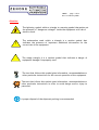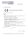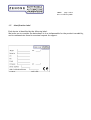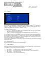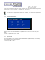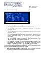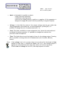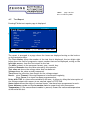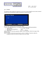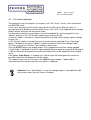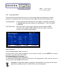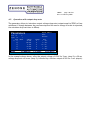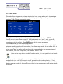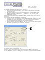
1
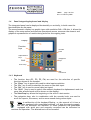
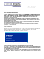
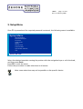
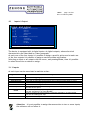
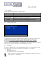
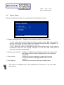
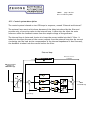
ZENONE Elettronica S.r.l.
Via Nazionale Pianopantano
83036 Mirabella Eclano (AV)
P.I. 02407830641
Tel. 0825449171 Fax 0825407907
Series GV and GTS static voltage generators
User’s Manual
Release: 16, February 2009
Controls: Firmware version V4.1
Display: Firmware version V2.2
DSP:
Firmware version V114
This manual is an integral and essential part of the product. Read carefully and completely the warnings
herein contained, they will provide important information regarding safety of operation and maintenance.
This equipment must be used only for the purpose for which has been designed. Any other utilization is
improper and therefore potentially dangerous. The manufacturer is not responsible for improper, incorrect
and unreasonable utilization of this equipment.
Any intervention on the equipment, that would cause a change in the structure or in the cycle of operation,
must be performed or authorized by the technical department of Zenone Elettronica.
ZENONE Elettronica S.r.l.
Via Nazionale Pianopantano 83036 Mirabella Eclano (AV)
Tel. 0825449171 Fax 0825407907
www.zenoneelettronica.it
[email protected]
Attention
This manual provides all the necessary information regarding the mode of
operation of GV and GTS generator series. For the correct use of a specific
equipment it is recommended to refer to the characteristics data sheet of
the generator which is an integral part of this manual.
Caltest Instruments GmbH
Kohlmattstrasse 7 Tel: +49(0)7842-99722-00
D-77876 KAPPELRODECK Fax: +49(0)7842-99722-29
[email protected] www.caltest.de
MUGL
page. 2 of 51
Rev. 16 February 2009
Series GV and GTS voltage generators
The series GV and GTS voltage generators are static sources of constant voltage. They will
supply the load with a set value of voltage independent from the value of the impedance¹
and the fluctuation of the power mains. They are used in test systems for electrical and
electronic equipments, measurement instruments and more general regulatory tests.
They can supply voltage at a variable frequency and/or DC, depending on the model²
selected.
They will give the following information on the running test:
• Voltage output
• Time of supply
• Load current
• Active power and reactive power consumption
• Complex load impedance
• Temperature of equipment under test³
They can have more scales for better precision and for better adaptation to the load.
They can be used as amplifier to reproduce any arbitrary voltage waveform.
They can be remote controlled by means of RS232 or RS485 serial interface.
1) According to the maximum output power allowed.
2) Only AC for GV models; AC and DC for GTS models.
3) With optional module
Test nr.
0000
Loop
000 / 000
Step
00 / 00
Voltage
0000.0 Volt
Time
0000000 mS
Frequency
50,00 Hz
Trigger
External
Phase Shift
90 Degr.
Temperature
18.5 °C
STOP
Start
ESC:
F1 Set
0000000 mS
0000.00 Volt
0000.00 Amp
0000.00 Watt
0000.00 VA
0000.00 VAR
P.F. 0.000
R 00000 mΩ
Z 00000 mΩ
X 00000 mΩ
F4: Report
Main page display
For devices equipped with the optional
MUGL
page. 3 of 51
Rev. 16 February 2009
Introduction
Thank you for choosing our product. We invite you to read this manual thoroughly because
here you can find the technical characteristics and all the necessary information for using
this equipment correctly.
The information contained in this document is subject to change without notice and it is
expected to be updated exclusively for the product for which is provided.
ZENONE ELETTRONICA is not liable for technical error, printing error or omissions that
might be encountered in this manual; neither is responsible for accidental or consequential
damages caused by the use of its product.
This guide provides specific information related only to the mentioned products.
No part of this manual may be reproduced in any form or by any means without our written
consent.
The software herein described is provided with end user license, unless otherwise
specified.
This technical document version voids and replaces all previous versions.
The products cited in this document could be trademarks and/or registered mark of
respective manufactures.
MUGL
page. 4 of 51
Rev. 16 February 2009
Summary
Preface............................................................................................................................. 6
1.1 How to use and understand the instructions provided by this manual .............. 6
1.2 Operating on the equipment keyboard .................................................................. 6
1.4 Compliance declaration .......................................................................................... 8
1.5 Identification label .................................................................................................. 9
1.6 Panel integrating keyboard and display ............................................................. 10
1.6.1
Keyboard ......................................................................................................... 10
1.6.2
BNC connectors ............................................................................................... 11
2. Preliminary operations ................................................................................................. 11
2.1 Working environment ............................................................................................ 11
2.2 Precautions ............................................................................................................ 11
2.3 Switching on the generator ................................................................................... 12
2.4 Presentation ........................................................................................................... 12
3. Setup Menu ................................................................................................................... 13
3.1 Inputs / Outputs ..................................................................................................... 14
3.1.1
Inputs ............................................................................................................... 14
3.2 Communication port .............................................................................................. 15
3.3 Password ................................................................................................................ 15
3.3.1
Operators ........................................................................................................ 16
3.3.2
Metrology technicians .................................................................................... 16
3.3.3
Primary password........................................................................................... 16
3.4 Report Setup ......................................................................................................... 17
3.5 Options ................................................................................................................... 18
3.6 Remote control ...................................................................................................... 18
3.7 Power modules ....................................................................................................... 18
3.8 System Date and time ........................................................................................... 19
3.9 Information ............................................................................................................ 19
4. Test ................................................................................................................................ 20
4.1 Test parameters input .......................................................................................... 21
4.2 EXTRA parameters ................................................................................................ 23
4.3 Test start ............................................................................................................... 24
4.4 Test cycle end ........................................................................................................ 24
4.5 Test Report ............................................................................................................ 25
4.6 Booster ................................................................................................................... 26
4.7 DC Control (optional) ............................................................................................ 27
4.8 Loop operation. ..................................................................................................... 28
4.10
Ramp mode ......................................................................................................... 30
4.11
Output polarity (Only DC generators with double polarities) ....................... 31
4.12
Remote mode ...................................................................................................... 31
4.13
PAUSE / RESUME function .................................................................................. 32
5 Metrology ...................................................................................................................... 33
5.1 Voltage calibration ............................................................................................... 33
5.2 Current calibration................................................................................................ 34
1.
MUGL
page. 5 of 51
Rev. 16 February 2009
6
7
Maintenance instructions ............................................................................................ 34
External connections ................................................................................................... 35
7.1 Sync signals (Trig) ................................................................................................. 35
7.2 DB15 I/O connections ............................................................................................. 36
7.3 DB9- RS485/RS232 serial connection ................................................................... 37
7.3.1
RS232 connection............................................................................................ 37
7.3.2
RS485 connection............................................................................................ 38
8 Fault and Failure signaling .......................................................................................... 39
9 Generator scheme ........................................................................................................ 40
10
Control system .......................................................................................................... 41
10.1
Control system block diagram .......................................................................... 41
10.2
Control system description ............................................................................... 42
10.3
Parameters function and definition ................................................................. 43
10.4
Fine tuning procedure for the control system ................................................. 45
10.5
Technique for fine tuning the loops ................................................................. 46
11
GesPWM software ..................................................................................................... 49
11.1
Connecting the equipment to a PC ................................................................... 49
MUGL
page. 6 of 51
Rev. 16 February 2009
1. Preface
1.1
How to use and understand the instructions provided by this manual
Conventional keys have been used in this manual to simplify and standardize the
utilization and the control of our generators.
In this manual you can find also functions that might not be present on the equipment
you have purchased; nevertheless proper information will tell you about eventual
limitations.
This solution has been chosen for clarity and to better evaluate the functional
characteristics available on all our products.
1.2
Operating on the equipment keyboard
•
•
•
•
•
•
•
1.3
The ENTER key is used to confirm the typed instructions; therefore pressing
this key the system will acquire the instructions.
The ESC key is used to exit the menu or to abandon the data input.
With the function keys (F1, F2 etc.) you get access to the system menu.
The available options in the menus can be selected either with the navigation
keys or with the encoder knob.
The tactile keyboard, on the integrated panel, is an alphanumeric type and a
pressure on the ↑ (Shift) key enables alternatively the various functions.
In some menus the possible choices are bind by preset values.
The manual start or stop of energy supply takes place always after a pressure on
the “Start/Stop” key.
Safety instructions
The following notes or graphic symbols list a series of instructions essential for the
correct use of the equipments. Such information could be found, in graphic form,
also on the equipment or used in the manual to focus the attention on the specific
issue. It is highly recommended to read such instructions carefully before equipment
installation.
Do not install the Generator
from those allowed
in environments with temperatures different
Do not expose the Generator to direct sun light
Do not pour any kind of liquids on the Generator.
In case of fire, use foam, CO2 or dry chemicals fire-extinguishers
MUGL
page. 7 of 51
Rev. 16 February 2009
Attention
The lightning symbol within a triangle is a warning symbol that points out
the presence of “dangerous voltages” inside the equipment with risk of
electric shock.
!
The exclamation mark within a triangle is a caution symbol that
indicates the presence of important additional information for the
correct use of the equipment.
The empty triangle it is a caution symbol that indicates a danger of
equipment damage if improperly used
The text that follows this symbol gives information, recommendations or
other particular instructions for the correct operation of the equipment
The text that follows this symbol gives information, recommendations or
other particular instructions in order to avoid danger and/or injury to
personnel.
A proper disposal of the shipment packing is recommended
MUGL
page. 8 of 51
Rev. 16 February 2009
1.4
Compliance declaration
MANUFACTURER DECLARATION OF CONFORMITY
The Zenone Elettronica Voltage generator :
GV series
GTS Series
are herewith confirmed to comply with the requirements set out in the Council Directive on the
Approximation of the Law of Member States relating to:
- Electromagnetic Compatibility, Directive 2004/108/EEC
EN 61000-6-1 - CEI EN 61000-6-1 (2° ed. 2007-10)
Electromagnetic compatibility (EMC) - Part 6-1: Generic standards - Immunity for
residential, commercial and light-industrial environments "
EN 61000-6-3 - CEI EN 61000-6-3 (2° ed. 2007-11)
Electromagnetic compatibility (EMC) - Part 6-3: Generic standards - Emission
standard for residential, commercial and light-industrial environments
EN 61326-1 :2006
Electrical equipment for measurement, control and laboratory use - EMC
requirements - Part 1: General requirements
- Low Voltage Equipment Directive (2006/95/EEC) and EN61010-1 (“Safety of Electrical
Measuring Apparatus”)
Mirabella 01-10-2008
Zenone Eletrronica S.r.l.
Luigi Zenone
Copyright Acknowledgement: EN publications are subject to the Copyright of IEC.
MUGL
page. 9 of 51
Rev. 16 February 2009
1.5
Identification label
Each device is identified by the following label.
We invite you to consider the data shown in it as indispensable for the product traceability,
and to communicate them for eventual request for support.
MUGL
page. 10 of 51
Rev. 16 February 2009
1.6
Panel integrating keyboard and display
The integrated panel can be deployed horizontally or vertically, in both cases the
functionalities are the same.
The monochromatic display is a graphic type with resolution 240 x 128 dots, it allows the
display of the setup menus and machine operational menus, moreover the numeric and
graphical representation of results during and after the ongoing tests.
Display
Function
keys
Alphanumeric
keys
Shift
Encoder
knob
Navigation
keys
Start/Stop
BNC
connectors
1.6.1 Keyboard
•
•
•
•
•
•
•
The function keys (F1, F2, F3, F4) are used for the selection of specific
functions shown at the moment.
The “Enter” key is generically used for data input acquisition.
The “Esc” key is used to abandon the menu or the data input.
The “Del” key is used to cancel data just typed.
The “Shift” ↑ key is used to switch from numeric keyboard to alphanumeric and vice
versa (the selected mode will be shown on the display).
The Start/Stop key allows the beginning or the end of a test session.
The navigation keys, also in combination with the encoder knob, are used to
scroll the reports, the menus, and to move around during values input.
Note: A malfunction of the keyboard/Display, or the removal of it from a
generator equipped with removable keyboard, will stop the ongoing supply,
but will not shutdown the machine. In these conditions the generators
equipped with serial port and remotely controlled can be instructed to
continue the operation. The aborted test will be canceled.
MUGL
page. 11 of 51
Rev. 16 February 2009
1.6.2 BNC connectors
Booster is used for external reference signal input. The specific functionality will be
shown in details later.
Trig. In allows to input a sync signal for locking-up the internal signal generator.
Trig. Out is the internal generator trigger output.
For the characteristics and the functionalities of the above signals look-up in the specific
sections.
2. Preliminary operations
2.1
Working environment
The Generator has been designed for indoor operation.
+ 5 °C °
!
2.2
+ 40 °C
Place the device on a suitable support or on a plane surface for good stability.
Be sure that proper ventilation is allowed and no objects obstruct the ventilation
openings.
Precautions
Operate the equipment at its rated power supply voltages, on earthed outlet
only.
Fasten on the output bolts suitable cable or bars of adequate section,
calculated on the bases of the machine functional characteristics.
WARNING:
Power connections can generate high temperature spots, that
could cause burnings.
WARNING:
All standard generators are supplied with output FLOATING,
not connected to any potential (unless otherwise specified); at the moment
of installation the output MUST BE CONNECTED TO GND OR TO ANY
POTENTIAL. Maximum allowed voltage on the output bolts, when not
connected to earth, is 300VAC.
MUGL
page. 12 of 51
Rev. 16 February 2009
2.3
Switching on the generator
Connect the generator to the power mains, it is recommended to follow the instructions
given on the equipment regarding voltage, frequency and earth connection, then turn
on the power switch, that could be located on the back panel or by the cabinet side
depending on the type of device.
In some models the power-on command can be part of an external power supply frame.
In some cases the integrated console, keyboard/display, can be connected to the cabinet
by means of an external cable.
At system power-on an auto-diagnostic routine is started for testing the most important
functionalities and detecting eventual faults.
In case of faults or malfunctioning, you must inform us in advance before you send the
equipment to our laboratories.
2.4
Presentation
At power on, after the auto-diagnostic test, on the screen appears the following mask that
displays the generator model and serial nr., the software versions, date and time.
On the task bar are shown the possible operative functions.
GTS300GL
Sn : 000000000000
FW version : VX.Y
LCD version : VZ.T
2009 February 07
F1: Test
10:27:12
F2 Setup
F3 Calibrat.
F4: Rem.
Pushing one of the shown keys the relative operative function is selected.
The access is granted after a valid password has been entered. At the time of shipment the
password “0000” is authorized, such password identifies the machine administrator which
has full operative access in all menus.
It’s advisable therefore to enter the SETUP menu, pushing the F2 key, to enable the access
codes for other operators, eventually to change its own password, or to set more desired
options.
MUGL
page. 13 of 51
Rev. 16 February 2009
3. Setup Menu
Once F2 is pressed and the required password is entered, the following menu is available:
Setup Menu
=>
Input and Output
Communication port
Password
Setup reports
Options
Remote mode
Power modules
System Date and Time
Info
Select an item
Select the desired operation moving the pointer with the navigation keys or with the knob,
and then press Enter.
Press ESC to exit the menu.
Follow this procedure to make selections in all menus.
Note: some selections may not be possible on the specific device.
MUGL
page. 14 of 51
Rev. 16 February 2009
3.1
Inputs / Output
Input and output
Input -------------- Action --------------------1)
Start Test
Stop Test
Start/Stop Test
End Test
=> 2)
3)
4)
Output
-------- Status ---------------------
1)
2)
3)
4)
Test running
Test params OK
End Test
Ext. Buzzer
Select an input or output
The device is equipped with 4 digital inputs e 4 digital outputs, whose electrical
characteristics are described in a later paragraph.
At each one of the four inputs it’s possible to assign a specific action and at each one
of the four outputs it’s possible to assign a machine status notification.
Selecting an input or an output with the cursor, and pressing Enter, then it’s possible
to select the action or status to assign.
3.1.1 Inputs
At each input can be associated a machine action:
Assigned function
Description
Start Test
Stop Test
Start/Stop Test
Start Consent
Test End
Starts the energy supply.
Stops the ongoing supply.
Starts and/or stops the ongoing supply only if the associated input is active.
Allows to start the supply only if the associated input is active.
Not to be used in this generator
At the end of the test the state (logic level) of this input is captured and
recorded in the report.
Allows to stop the ongoing energy supply (and record the event in the report)
until the activation by an input RESUME.
Allows to resume the energy supply, previously stopped by an input PAUSE,
from the succeeding test step.
Supplies current only if the associated input is active
Status (1 to 4)
PAUSE
RESUME
ENABLE
Attention: it is not possible to assign the same action to two or more inputs,
the software will not allow it.
MUGL
page. 15 of 51
Rev. 16 February 2009
3.1.2 Outputs
At each output can be associated a machine status:
Assigned function
Description
Data entered
Test started
Ongoing test
It means that the data entered are sufficient to start an energy supply
The device waits for an external enable to start the energy supply
The generator is supplying energy
The generator has stopped the current/voltage supply for a non expected
external event, for example: Trip, Overload, etc.
It shows a device malfunctioning
It means that the generator has terminated the test cycle correctly
Allows to use a remote acoustic device for signaling
Abnormal status
Failure
Test End
External buzzer
3.2
Communication port
Communication port
=>
Bus address
Baud Rate
01
9600
www.mpsystems.it e-mail= [email protected]
Select an item
The generator is equipped with an RS485 communication port, which allows to connect a
maximum of 32 devices on the same 2 wire line, and with an RS232 port for PTP
connections. The two serial ports can be used alternatively, one or the other.
The address Bus is used to identify each device and accepts values from 1 to 32.
Baud Rate is the transfer speed and is selectable from 4800 to 57600 baud; it is possible to
select with the cursor the desired baud rate among those available.
3.3
Password
The device is equipped with a more levels password system, this allows a partial or total
access to the various functions. It’s possible to define them on the bases of:
• Operators
• Metrology technicians
• Main password (for machine administrator)
Note: It’s possible to disable the password management completely, entering a
“null” password as administartor.
MUGL
page. 16 of 51
Rev. 16 February 2009
3.3.1 Operators
The names and the codes to be linked with the operators (max. 10) must be defined; such
operators are enabled only to run the tests.
The numeric code, max. 4 digits, is the access password used by the operators while the
name, max. 10 characters, will be written in the test reports.
3.3.2 Metrology technicians
The names and the codes to be linked with the technicians (max. 10) must be defined,
such technicians are enabled only for machine verification and calibration.
The numeric code, max. 4 digits, is the access password used by the technicians while the
name, max. 10 characters, will be shown on the calibration mask.
3.3.3 Primary password
The primary password (administrator) enables the access to all functions: menu, test and
calibration.
In this menu it’s possible to change the password, entering a 5 digit (max.) code and
reentering it for confirmation.
Note: To define a “null” password just press Enter, without typing anything,
when a new password is asked for.
On request it’s possible to implement a super password in the management
software, defined in the factory and not changeable, useful in case more
equipments are purchased and it is wished to access all devices with only one code,
independently from the single passwords.
MUGL
page. 17 of 51
Rev. 16 February 2009
3.4
Report Setup
Defines the different modes for recording and/or deleting test reports.
Setup reports
=>
Circular archive
Enable remote clear
Clear archive
Show reports
Yes
Yes
Select an item
• Circular archive(Yes/No): Enables to save the test results in rolling mode.
If “Yes”, when the record is filled-up with test reports (max. 400), the operation
goes on overwriting the older reports. An asterisk near the wording “F4:Report” in
the test mask means that overwriting has occurred.
If “No”, When the record is filled-up no other tests will be saved. In this case an
exclamation mark near the wording “F4:Report” in the test mask means that no
other test reports are memorized.
• Remote clear (Yes/No): Enables or disables the possibility to delete the reports from
the memory with a remote command (ex: from a Personal
Computer).
• Clear archive:
Deletes all records completely, emptying the entire
archive definitely and bringing back to zero the test
counter.
• Show reports:
Allows a direct access to the report display menu.
This menu is accessible only to the administrator, therefore no one can delete
the records.
MUGL
page. 18 of 51
Rev. 16 February 2009
3.5
Options
Options
=>
Language
Beep on keys
Beep on events
English
Yes
Yes
Immediate start
Auto range
No
No
Select an item
In this menu it’s possible to select the language (Italian or English); it is possible to
enable or disable respectively the beep on the key, being pressed (Beep on keys),
and/or at the appearance of an event (Beep on events).
The option “Immediate start”
• If “Yes” is selected, the output starts immediately after the start key has been
pressed (or external consent is given).
• If “No” is selected, the output begins only when the mains crosses the zero.
The last option “Auto range”, if enabled, causes the automatic change of scale during the
test, this means that the change of the output value, done by means of the encoder knob
(or by means of a reference voltage on devices equipped with DC Control), will extend
over the entire range of the equipment operation.
If this function is disabled the, change of the output value will occur only within the range of
the selected scale.
3.6 Remote control
At the moment this item has not been implemented.
3.7
Power modules
Some devices are equipped with power modules for power supervisory; with this menu
it’s possible to check some functional parameters.
•
•
•
•
FW version:
AC voltage:
DC voltage:
Temperature:
Firmware version of the supervisory module.
Mains supply voltage (in some cases this value is always at 0).
Power bus voltage.
Power module temperature.
MUGL
page. 19 of 51
Rev. 16 February 2009
If the device is equipped with more power modules, each one has a dedicated page and by
means of the arrows it’s possible to visualize their information.
For devices not equipped with supervisory modules, this menu is not implemented.
3.8
System Date and time
System Date and Time
=>
Year
Month
Day
2008
January
02
Hours
10
Select or ESC: Menu
Minutes
32
Seconds
47
F1: Update
With the cursor select the parameters to update, type-in the correct value and press
Enter.
Press F1 to update the system clock.
3.9
Information
This menu provides some functions that are relative to the equipment being used, among
which the device activity counter (hours).
If wished press F1 to clear it.
MUGL
page. 20 of 51
Rev. 16 February 2009
4. Test
On the bases on the type of construction and configuration, our generators can do the
following:
• Supply alternate and/or direct constant voltage.
• Continuous mode output or impulsive mode output.
• Supply voltage for periods of time settable by the user and make a cyclic
repetition of the programmed process.
• Allow to change the intervals of time, between one process and the next, by 1 sec
minimum.
• Generate power supply loops.
• Simulate cycles with power dropouts (output at 0) for intervals of time defined by
the user.
In the following pages, the words STEP and CYCLE are mentioned frequently, therefore an
explanation is given on their meaning right below:
STEP:
For STEP we intend a voltage output for a defined period of time.
As we’ll see later it’s possible to define more steps.
CYCLE: The CYCLE is a set of one or more steps that are executed one after the other
when a test is started. It’s possible to define to run the same cycle a certain
number of times (or even forever).
Press F1 to enter the test mode; once the operator password has been recognized, the
system will display the parameters setup of the last test session. Move the cursor, with
the knob or with the navigation keys, to select the items to be changed with the new
settings.
MUGL
page. 21 of 51
Rev. 16 February 2009
4.1
Test parameters input
Parameters
Test nr.
1
Temperature:
20,7
Cycle nr.
10
Step
Voltage
=>
Start
Mode
Operat.
Code
Remarks
John
XYE
abcd
Pause:
1 sec
Range
Time
1)
2)
50 Volt
75 Volt
1
1
10 Sec.
10 Sec.
3)
100 Volt
1
10 Sec.
F1: Booster
F2: Extra
->
ESC:Menu
•
The field Operat. shows the name linked to the operator code.
•
The field Code allows to enter 12 alphanumeric characters (will be written
back in the report).
•
The field Remarks allows to enter 12 alphanumeric characters (will be written
back in the report).
•
The field Temperature, available only on some generators equipped with the
optional measurement module and the probe PT100, shows the ambient
temperature.
•
The field Cycle nr. defines the number of times the process has to be
repeated. With 0 the cycle is repeated indefinitely.
•
The field Pause defines the interval of time between cycles, expressed in the
unit selected with F3. Intervals of time less than one second (1 sec.) are not
allowed. If the Cycle nr. is set to 1, the field Pause will not be shown.
It starts here the definition of the actual supply cycle, which can be divided in more
steps. For each step several parameters must be defined.
•
Step: depending on the model it’s possible to set from 1 to 30 steps. An arrow in
the bottom right hand corner shows the availability of more steps.
MUGL
page. 22 of 51
Rev. 16 February 2009
•
Mode: In this field it’s possible to select:
with F1 the loop operation
with F2 the ramp operation
with F4 the output polarity, positive or negative (if the generator is
designed to supply DC power with the possibility of negative output).
•
Voltage: In this field the value of the output voltage must be set within the
range suggested by the status bar. In some equipments, pressing F3, it’s
possible to change the unit of measurement (mV, V).
•
Scale: This field, available on some equipments only, shows the scale selected
by default for better precision. It’s possible to change the scale but the
precision could be impaired.
•
Time: This field allows to set the length of time for the voltage output. Pressing
F3 it’s possible to change the unit of measurement (mS, Seconds, Minutes,
Hours).
Note: If the voltage is set to 0, a power drop-out is produced for the length of time
defined in that step, if instead the time is set to 0, the voltage output is
applied for unlimited time (the steps that follow will not be executed).
If both time and voltage are set to 0, the step sequence is ended.
MUGL
page. 23 of 51
Rev. 16 February 2009
4.2
EXTRA parameters
Depending on the type of equipment, pressing F2, an additional page of parameters
could be available.
•
Generator Mode:
allows to select the AC or DC output (available only on some
devices).
•
Trigger:
It allows to synchronize the zero-crossing of the output
voltage:
Internal (if the power mains synchronism is provided).
External (by means of TRIG IN input).
Automatic (free running).
•
Frequency:
Output voltage frequency (selectable on the bases of the
Trigger and the specific characteristics of the Generator).
•
Phase shift:
Sets the phase shift between the trigger and the zero-crossing
of the output voltage from 1 to 359º (not possible with
automatic trigger).
•
Delay after TRIP:
Allows to delay the interruption of the voltage output with
respect to an external signal of TEST END.
•
AUTO-RESUME time: It’s possible, if other than zero, to resume the output after
some delay (max. 999999 ms) when the equipment is in the
PAUSE state (look at PAUSE/RESUME function).
Press ESC to return to the PARAMETERS page.
Once the setup as been completed it's possible to start the test by pressing the
START/STOP key.
MUGL
page. 24 of 51
Rev. 16 February 2009
4.3
Test start
Pressing START the voltage output is active and the display will update in real time the
various numeric indicators.
The amount of information displayed depends on the type of equipment.
While the output is active it’s possible, after pressing F1, to change the value of the
set voltage with the encoder knob.
Rotating the knob, the numeric values shown can be changed more or less rapidly,
according to the speed of rotation. Further, moving the cursor with the right/left
arrow keys, the change can be done in units, tens, etc..
Pressing F1 again, or at the end of the step, the manual change mode is abandoned.
This function is not compatible with limited time outputs.
Note: If the item “Auto range” in the menu SETUP-OPTIONS is enabled, going
over the scale range manually, we step into the next scale, therefore the
maximum limit that can be reached is the maximum allowed.
4.4
Test cycle end
At the end of the step sequence, the setup, the result and the measured values will be
shown on the display and stored in the test report archive.
If the programmed step sequence is terminated correctly and the number of cycles to
be executed is grater than one, the cycle will be repeated automatically after the time
being defined in pause is elapsed.
It’s possible to stop the voltage output at any time by pressing START/STOP key. In
this case no information is stored in the report.
Pressing F1 one goes back to the test parameters; pressing F4 the test reports are
displayed.
Note: an eventual asterisk beside “F4: Report” means that the maximum
number of stored tests has been exceeded, therefore the older one will be
overwritten. An exclamation mark means that no new test will be stored
until the previously memorized tests are deleted.
MUGL
page. 25 of 51
Rev. 16 February 2009
4.5
Test Report
Pressing F4 the test reports page is displayed.
Test number
Test Report
Date
Hour
Operator
Code
Remarks
Test value set
Voltage
Time
Result
pa
<-:
Prev.
1 ->
7
7
2008 July 05
16:10:17
John
150.0 Volt
149,9 Volt
1 sec
TIMEOUT
->: Next
↓ / ↑: UP/DN
+
ESC: Exit
The report is arranged in a page where the items are displayed acting on the knob or
on the navigation keys.
The Test number shows the number of the test that is displayed, the two digits right
below show the field of progressive report number that can be displayed, acting on the
left/right arrows, from the first stored to the last.
The date is shown in the european format: year, month, day.
Code and Remarks show the data entered by the operator.
Test value set shows the voltage value that has been set.
Voltage shows the value actually measured.
Time shows the effective time length for the voltage output.
Result: gives Timeout if the step sequence is terminated regularly;
gives Pause if an input has been programmed so.
Delay after TRIP is a time value settable by the user, it allows to delay the interruption of
the voltage output with respect to an external signal of TEST END.
Status inputs shows the state of eventual inputs, that have been programmed as such.
Pause between cycles and Cycles number set are respectively test parameters.
Temperature (if the measurement module is present) shows the measured temperature
at the end of the test.
MUGL
page. 26 of 51
Rev. 16 February 2009
4.6
Booster
The booster mode enables the generator to work as a power amplifier and can be activated
directly from the parameters page by pressing the function key F1.
Booster Mode
Range
1
www.mpsystems.it e-mail= [email protected]
GI240AGL
Start
Enter:
ChangePower
Modular
ESC: Exit
Systems
Set the scale, selecting the one that suites better.
Connect the signal generator to the Booster observing the following parameters:
• Analog input:
0 … 10 Vpk (20 Vpp).
• Minimum input impedance:
1 KΩ.
• Bandwidth:
DC, 10 … 1000 Hz.
With an input of 10 Vpk the maximum output can be obtained, within the range of the
selected scale.
Note: In Booster mode the automatic gain control is disabled, therefore when the
frequency varies the effective output level can change.
MUGL
page. 27 of 51
Rev. 16 February 2009
4.7
DC Control (optional)
The generators can be equipped, on request, with “DC Control” mode, which substitutes
the BOOSTER mode.
In this case, connecting a DC control signal (from 0 to 10V) to the “Booster” input, it’s
possible to control, directly from the outside (for ex. with a PLC), the amplitude of the voltage
output, without acting on the front panel knob.
It is during the setup of test parameters that can be decided to use the equipment in the
“Normal” mode or in the “DC Control” mode by pressing the key F1.
If “Normal” mode is selected, it’s valid what previously stated: setup step by step for voltage,
for time, etc…..
If “DC Control” mode is selected, then only the scale can be specified (if the “Auto range”
option is disabled in the menu “Options”) and the maximum time for the voltage output.
The items in the menu “F2:Extra” are available in both cases.
Pressing START begins the voltage output, that is proportional to the dc voltage applied.
If “auto range” is disabled, to a 0V dc signal applied will correspond an output of 0 Volt and to
a 10V dc signal will correspond the maximum amount that can be supplied for the selected
scale.
If the option “Auto Range” is enabled, to a 10V dc signal will correspond the maximum
possible output that the equipment can be supply.
The response time, due to a change in the applied control voltage, is about 100 ms
measured from the moment when the new value is stabilized.
Attention: If the “Auto Range” is used, the voltage output is interrupted for 400
milliseconds every time the scale is changed.
MUGL
page. 28 of 51
Rev. 16 February 2009
4.8
Loop operation.
This operation mode allows to run two or more output steps repeatedly and without
pauses, for unlimited time. The differences with respect to the cycle operation are:
Cycle operation:
At the end of the defined steps the test report is recorded, the display
is updated with the result, a pause is inserted (min. 1 sec.), the cycle
is repeated.
LOOP operation:
When the LOOP instruction is reached, the test report is NOT
recorded, the display is NOT updated with the result, the same
sequence is repeated immediately.
Operat. Master
Code
Remarks
Parameters
Test nr.
Cycles nr.
Step
=> 1)
2)
3)
4)
5)
Start
948
1
Mode
Voltage
30 Volt
120 Volt
Range
2
2
Time
1 Sec.
2 Sec.
LOOP
0 Volt
0 Volt
F1:Booster
2
2
F2: Extra
0
0
Sec.
Sec.
ESC:Menu
How to operate:
Set the voltage output steps (at least 2).
Set the cursor at the end of sequence (in this case on step 3), press ENTER to confirm,
press F1 to activate the LOOP mode.
Press Start/Stop to run the test.
To stop the operation press Start/Stop.
To cancel the LOOP mode, press F1 to go back to the parameters mask, set the cursor on
the loop step, press Enter and then F1.
Attention: Setups that require a change of scale between one step and the other
generate an output drop-out of 400 ms due to switching time.
MUGL
page. 29 of 51
Rev. 16 February 2009
4.9
Operation with output drop-outs
The generator allows to introduce output voltage drop-outs (output equal to ZERO) of 1ms
minimum (If though between the previous step and the next a change of scale is expected,
the minimum drop-out time is 400ms).
Operat. Master
Code
Remarks
Parameters
Test nr.
Cycle nr.
Step
=> 1)
2)
3)
4)
5)
Start
8
1
Mode
Voltage
30 Volt
120 Volt
0 Volt
50 Volt
0 Volt
F1:Booster
Range
2
2
2
2
2
F2: Extra
Time
1 Sec.
2 Sec.
30 ms
1 Sec.
0 Sec.
ESC:Menu
In the example shown above, after the output voltage of 120V for 2 sec. (step 2), a 30 ms
voltage drop-out will occur (step 3), followed by a further output of 50V for 1 sec (step 4).
MUGL
page. 30 of 51
Rev. 16 February 2009
4.10 Ramp mode
This mode allows to generate voltage outputs in a linear ramp fashion, with increasing or
decreasing voltage values and settable ramp timings (optionally are also possible a
maximum of 8 different exponential ramps).
Operat. Master
Code
Remarks
Parameters
Test nr.
Cycle nr.
Step
=> 1)
2)
3)
4)
5)
Start
2
1
Mode
R
R
Voltage
30 Volt
120 Volt
0 Volt
50 Volt
0 Volt
F1:Booster
Range
2
2
2
2
2
F2: Extra
Time
1 Sec.
2 Sec.
30 ms
1 Sec.
0 Sec.
ESC: Menu
How to operate:
Set the cursor on the step where the ramp has to be activated and press ENTER.
Press F2 once to select linear ramp (“R” will be shown in the “Mode” field), press F2 a
second time to select exponential ramp (“Re” is shown in the “Mode” field if the machine
is equipped with this option). Press ENTER again for the other parameters.
Press START/STOP to start the voltage output.
In the first step, of the example shown above, the generator will start the output with the
minimum amount possible and then reaches, in a linear ramp mode, the set value (30V) in
the time assigned (1 Sec.).
In the second step the output will start from the value reached in the previous step and
then reaches, in a linear ramp mode, the value of 120V in 2 Sec.
Note: In the steps where the RAMP mode is active, it is not possible to set infinite
time.
The ramp mode cannot start from a scale (ex. scale 1) e terminate in the next step with
another scale (ex. scale 2). Further in the DC generators with double polarity, it’s not
possible to start a ramp with a voltage polarity and terminate it with the opposite polarity.
Use two separate ramps (for the positive part and for the negative part) with a step at zero
in between.
MUGL
page. 31 of 51
Rev. 16 February 2009
4.11 Output polarity (Only DC generators with double polarities)
In the voltage generators, capable to supply power in both polarities, it’s possible to define
the polarity at each step.
Operat. Carlo
Code
Remarks
Parameters
Test
nr.
Cycle nr.
Step
=> 1)
2)
3)
4)
5)
8
1
Mode
+
+
+
+
Start
Voltage
30 Volt
120 Volt
0 Volt
50 Volt
0 Volt
F1:Booster
Range
2
2
2
2
2
F2: Extra
Time
1 Sec.
2 Sec.
30 ms
1 Sec.
0 Sec.
ESC: Menu
How to operate:
Set the cursor on the step where the polarity is intended to be changed and press ENTER.
Press F4 (the polarity will be inverted) and then enter the other step parameters.
4.12 Remote mode
With this option it is possible to control the generator from a Personal computer by means
of the serial communication port RS485 or RS232. This mode is entered directly from the
initial display mask pressing F4.
REMOTE CONTROL
F1: Active
Menu
Modular Power ESC:
Systems
Press F1 to activate the remote control. The equipment will not allow any other operation
locally.
To resume local control press F2 and then ENTER.
MUGL
page. 32 of 51
Rev. 16 February 2009
4.13 PAUSE / RESUME function
If the digital inputs are adequately programmed (see the relative section) it’s possible to
accomplish the PAUSE / RESUME function.
The activation of an input PAUSE will cause the interruption of the output voltage and the
data produced at the moment will be recorded in the test report.
Differently from STOP, in this case it’s possible to resume the output in two ways:
•
With the START/STOP key or a “START” input or a “START/STOP” input or a remote
START, as normally happens with a new cycle and the equipment stopped.
•
From the next step by means of a RESUME input or after some Auto-RESUME time
(to be defined in the page relative to the EXTRA PARAMETRS of the test).
Obviously this means that more voltage output steps must be defined. The situations that
could arise are:
•
If a successive step is defined, the output resumes from it.
•
If a successive step is not defined, nothing happen.
•
The successive step is not defined, but has been programmed the execution of a
number of cycles other than 1, the output then resumes from the first step of the
successive cycle.
•
If LOOP is active in the successive step, the output resumes from the first step.
Further, if it’s whished to abandon the PAUSE status, without initiating a new voltage output,
it’s possible to activate a STOP input or to send a remote STOP.
NOTE: When the function PAUSE is activated the test report is produced, therefore
if the output is restarted with RESUME the test number is automatically
incremented.
MUGL
page. 33 of 51
Rev. 16 February 2009
5
Metrology
The installed software allows periodic metrological controls by technicians enabled by the
administrator.
Before the metrological verification is started, the test circuit must be set up using
measurement instruments with a precision class superior to that of the generator (see the
technical characteristics).
To enter the calibration menu, press F3 in the main display mask, type the
password and press ENTER.
If the ambient temperature measurement module is present with PT100, the measured
temperature will be shown in the top right hand corner of the display. This value is
continuously updated if shown on a white background, on the other hand if it’s shown on a
blue background will be the last measured value.
5.1
Voltage calibration
Connect to the output generator clamps a resistive load between 20% and 60% of the
nominal load for the scale that has to be calibrated.
1) Select the scale (range) and press Enter.
2) At the request “Set” will be shown by default the full scale voltage value, It’s
possible to change it if wished. Press Enter.
3) Press START/STOP to start the output, or press F3 to recall the factory DEFAULT
values.
The generator will supply the voltage value entered for about 10 sec.
Read the value measured with the reference instrument and, if different from the one
previously entered, press F1 to proceed for the correction and enter the value just
measured.
Press ESC to continue with the next scale (range).
MUGL
page. 34 of 51
Rev. 16 February 2009
5.2
Current calibration
Connect to the output generator clamps a load between 60% and 100% of the nominal load
for the scale that has to be calibrated.
1) Select the scale (range) and press Enter.
2) At the request “Set” the default full scale voltage value will be shown, change it
according to the load in order to get the wished current. Then press Enter.
3) Press START/STOP to start the current supply, or press F3 to recall the factory
DEFAULT values.
Read the value measured with the reference instrument and, if different from the one
shown on the display, press F2 to proceed for the correction and enter the value just
measured.
Press ESC to continue with the next scale (range).
6
Maintenance instructions
•
Check periodically the ventilation openings, clean them and/or substitute the filter;
•
Do not use solvents to clean the keyboard and the display;
•
Check periodically that the connection bolts between the power outputs and the
external test circuit are tighten.
MUGL
page. 35 of 51
Rev. 16 February 2009
7
External connections
7.1
Sync signals (Trig)
The generator is equipped with two sync signals ”Trig. In” and “Trig. Out”, these allow to
assemble three-phase systems, voltage generators synchronized with current generator,
generators connected in parallel, etc.
Device 1
Current/Voltage
generator
In
Device 2
Device 3
Current/Voltage
generator
Current/Voltage
generator
In
Out
Out
In
Out
Example of a three-phase system:
The device nr.1 is set up, in the Extra parameters of the menu “Test”, with trigger internal
(if present) or auto.
The devices nr. 2 and 3 are set up with trigger external and 120 degrees phase shift, so
that the internal generator is 120 degrees out of phase with respect to “Trig. In”, while the
signal “Trig. Out” is always in phase with the internal generator.
Electrical characteristics:
• Trig. In:
Accepts an open collector input signal (max. 10 mA).
24V
Trig IN diagram
Trig IN
GND
•
Trig. Out:
It’s an open collector output signal. Maximum voltage at the
terminals 50V, maximum current 20 mA.
Trig OUT
GND
Trig OUT diagram
MUGL
page. 36 of 51
Rev. 16 February 2009
7.2
DB15 I/O connections
This connector allows to use 4 inputs and 4 outputs opto-isolated and programmable (as
defined in the specific section).
DB15 Pin Out
Vout 24Vdc max 100mA
9
in1
1
in2
in3
in4
2
10
3
11
4
12
+24V
out1
out 2
out 3
24V
13
24V
(20-30V)
out 4
14
Common inputs
5
Max current each input can
sink: 4mA at 24Vdc
15
Common outputs
Max output current at each
output: 500mA
The 4 inputs refer to a common pin (pin 5), which is galvanically isolated with respect to
the common output pin (pin 15). It’s possible to connect them together if wished.
To work correctly the outputs need a 24Vdc voltage, capable to supply the total current
(500 mA max X 4). If wished it’s possible to use the voltage available at pin 9, if the total
current of 100 mA is sufficient.
MUGL
page. 37 of 51
Rev. 16 February 2009
7.3
DB9- RS485/RS232 serial connection
This connector allows to connect the equipment to a PC with a dedicated cable (RS232
mode) or using a RS232/RS485 converter cable.
7.3.1 RS232 connection
In order to connect a device directly to the RS232 serial interface of a PC it is necessary to
make a special cable with the following connections:
PC side
Pin type
RXD
TXD
DTR
GND
DSR
RTS
CTS
9 poles (25 poles)
2 (3)
3 (2)
4 (20)
5 (7)
6 (6)
7 (4)
8 (5)
Equipment side
9 poles
7
8
6
9
1
2
3
4
Attention! This connector, being adaptable to both interfaces, it’s not
compatible with standard cables.
MUGL
page. 38 of 51
Rev. 16 February 2009
7.3.2 RS485 connection
In order to connect, on the same serial line, one or more devices (max 32) to a PC RS232
serial port, it’s necessary to use a RS232/RS485 converter. In this case the following
pins on the equipment connector must be used:
Pin
Pin
Pin
Pin
Pin
1
2
3
4
5
A
Res. 120 (1)
Res. 120 (2)
B
GND
It is possible then to put together this type of system, taking care to terminate the line
with a 120-ohm resistor.
RS232/485
Converter
PC
A
B
120
ohm
B
A
Device 1
B
A
Device 2
B
A
Device 3
It’s possible to use, as terminal resistor, the one already connected between pins 2 e 3 of
the RS485 connector on board on each equipment.
MUGL
page. 39 of 51
Rev. 16 February 2009
8
Fault and Failure signaling
The generators are equipped with system auto-diagnosis and in case of anomalous event
they stop the supply and an error message is shown on the display as in the table below:
Signaling
Cause
Action
Over-temperature
Temperature out of limits
Under-voltage
Voltage on the power mains
too low <350V
Over-voltage
Power mains voltage too
high >460V
Current limit
Current supply over the
maximum value allowed
Fault in the temperature
measuring circuit
IGBT failure
Error in the capacitors precharge circuit
The supply of power is over
the maximum allowed
Shut down the equipment
and wait few minutes. If the
fault persists, check the
ventilation ducts, they must
be clear, and make sure
that the fans work properly
Check the power mains
voltage or the presence of
all three phases
Check the power mains
voltage or eventual
regeneration from the load
Check the load or the
regulation parameters
Call the assistance
Thermal sensor
Fault signal
Pre-charge
Overload
Call the assistance
Check that the pre-charge
relay works correctly
Reduce the load
If the malfunctioning has not been fixed, please contact the assistance.
MUGL
page. 40 of 51
Rev. 16 February 2009
9
Generator scheme
V3
Mains
Rectifier
IGBT bridge
Filter
I3
1
V2
I2
1
V1
I1
1
Output
Transformer
Serial interface
PWM
modulator
Digital I/O
µP
Control unit
Booster
Synchronization
HMI interface
Voltage generator model GV 3 scales - Block diagram
MUGL
page. 41 of 51
Rev. 16 February 2009
10 Control system
The generator is equipped with a sophisticated digital control system, which has to keep
the voltage output constant independently from load change and mains variations.
The regulation is based on two PID algorithms in sequence and named:
“External” with feedback voltage taken at the output,
“Internal” with feedback current taken before the filter.
The following figure shows the principle of operation
10.1 Control system block diagram
REF / X
Feed-forward
External loop
Internal loop
+
Voltage
reference
+
REF1
+
REF
+
REF2
-
-
Output
voltage
Primary
current
Z.TR
+
PWM
The control loops are adjusted in production in order to achieve a good compromise
between speed and stability for the majority of loads, in some cases it might be
necessary to modify some parameters for the following reasons:
•
•
•
Oscillations due to the type of load too reactive
To enhance the generator dynamic performance
To adapt the generator to the load
MUGL
page. 42 of 51
Rev. 16 February 2009
10.2 Control system description
The control system is based on two PID loops in sequence, named “External and Internal”.
The external loop reacts a bit slower because of the delay introduced by the filter and
provides only a correction value to the internal loop. It takes into the input the main
reference while the feedback comes from the output voltage of the generator.
The internal loop is faster and its aim is to keep the current stable into the LC filter. It
takes into the input the sum of the current request from the external loop plus the current
circulating into the load (active compensation of the internal impedance or feed-forward),
the feedback is taken from the current before the filter.
External loop
Direct reference to
modulator
REF (from internal
generator or
BOOSTER input)
Integral limitation
+
+
+
+
Lim. slope
Output voltage
Derivative limitation
REF1
to internal loop
MUGL
page. 43 of 51
Rev. 16 February 2009
Direct reference
Internal loop
Output current
Z.T.R.
REF1 (from
external loop)
+
Integral limitation
+
+
+
REF2
+
+
-
Primary current
(before the filter)
+
Gain
To
modulator
Amplitude
Derivative limitation
10.3 Parameters function and definition
Lim. Slope:
range 0 ÷ 99 (0 = no limitation)
It limits the positive slope or negative slope of the reference in order to cancel eventual overshoots on the
output voltage caused by variations of the reference too steep.
Direct reference: range 0 ÷ 20 (16 equals to 100%)
It’s the amount of direct reference (set up voltage) to apply directly to the modulator and is expressed in
terms of sixteenths of the reference. It allows to anticipate the modulation value before the execution of the
PID calculations. If this value increases the generator becomes more reactive (the bandwidth widens) at the
expense of stability.
Feed-forward:
range 0 ÷ 20 (16 equals to 100%)
It’s the amount of output current to add to the external loop correction. This parameter is needed to
compensate the generator output impedance (it means that to a current increment gives a percent increment
of the output voltage). Its regulation is rather critical and it’s suggested to modify it only in cases of
impulsive loads. If this value is incremented the generator can oscillate.
Kp:
range 0 ÷ 10000
It’s the proportional gain of the regulation loop (it causes the output to change according to the input error)
MUGL
page. 44 of 51
Rev. 16 February 2009
Ti:
range dt ÷ 32000µS; 0 = integral disabled
It’s the integration time of the regulation loop in microseconds, can be applied directly or multiplied by the
parameter Kp (causes the output to change with a speed proportional to the error, sets the regulation point
canceling out the offset).
Td:
range dt ÷ 32000µS; 0 = derivative disabled
It’s the derivative time of the regulation loop in microseconds, can be applied directly or multiplied by the
parameter Kp (causes the output to change proportionally to the rate of change of the input, reduces the
system response time).
dt:
machine cycle time not changeable.
Positive integral limitation:
range 0 ÷ 100%
It is the maximum value the integral variable can take
Negative integral limitation:
range 0 ÷ 100%
It is the minimum value the integral variable can take
Positive derivative limitation: range 0 ÷ 100%
It is the maximum value the derivative variable can take
Negative derivative limitation: range 0 ÷ 100%
It is the minimum value the derivative variable can take
Z.T.R. block
The Z.T.R. block provides for wave shape correction during the zero crossing (dead time
correction) adding a further gain when the current crosses the zero. The fine tuning of this
block is done with sinusoidal or triangular wave shapes.
Z.T.R. gain:
range 0 ÷ 100
It’s additional gain during the period when the current crosses the zero.
Z.T.R. amplitude:
range 0 ÷ 100
It’s the maximum correction value, previously calculated, for the modulator.
MUGL
page. 45 of 51
Rev. 16 February 2009
10.4 Fine tuning procedure for the control system
Note: To change the control parameters it’s necessary to have a PC connected to the serial port of the
console and the software program “GesPWM”. (Look at paragraph “GesPWM software”)
The following paragraph provides only a guide for the fine tuning of the PID regulation
loops since in many cases a fixed rule it’s not applicable and regulations are made on the
bases of personal experience.
Note:
Eventual parameters modifications must be done by specialized
personnel only because these modifications could cause malfunctions and/or
generator damages.
Note:
Before making any change to the regulation parameters it’s advisable
to take note of the existing parameters so to restore the initial setup if
needed.
In the majority of cases, in particular when it’s necessary to adapt the generator to the
load, it’s sufficient to make light changes to some parameters following simple rules:
In case of sever capacitive load, lower the Kp coefficients and increase the
integration time Ti.
In case of sever inductive load, increase the Kp coefficients and lower the
integration time Ti.
MUGL
page. 46 of 51
Rev. 16 February 2009
10.5 Technique for fine tuning the loops
The fine tuning of the PID loops must be done in two phases, first the internal one and then
the external.
In order to fine tune and verify the dynamic performances of the generator, it’s better to
set the current with an external generator connected to the BOOSTER input, using a square
waveform with the following test parameters:
Frequency => between Fmin and Fmax (Fmin < fr < Fmax).
Amplitude pk-pk => 0 ÷ 10V.
Ti,, Td and adjust the
Under these conditions set to zero the external loop parameters Kp, Ti
internal loop parameters Kp, Ti and Td to obtain the maximum performance.
Once the internal loop has been fine tuned, the parameters Kp, Ti and Td of the external
loop can be adjusted so to optimize the global performance.
Ideal system response to a step function
MUGL
page. 47 of 51
Rev. 16 February 2009
Step function response varying Kp with Ti constant
Step function response varying Ti with Kp constant
MUGL
page. 48 of 51
Rev. 16 February 2009
Step function response with Kp too high
Step function response with Kp and Ti too small
MUGL
page. 49 of 51
Rev. 16 February 2009
11 GesPWM software
The “GesPWM” software is compatible with WINDOWS XP systems and allows to set up
some important parameters of the generator; must be installed on a suitable PC and
executed.
Such software has been designed to set up the parameters of divers equipments we
manufacture, therefore it’s possible that some parameters might been shown that have no
function for this particular generator.
11.1 Connecting the equipment to a PC
The equipment must be connected to the PC trough the serial port of the console by means
of the specific cable.
After the connection has been done and the program GesPWM is launched, the following
mask will appear:
By means of the menu “Set” it’s
possible to select the parameters
of the serial communication:
PC port and baud-rate
1
4
2
3
MUGL
page. 50 of 51
Rev. 16 February 2009
The following parameters must be entered in position “2”:
• Device address (indirizzo macchina): serial address of the generator (look at the
specific paragraph)
• DSP address (indirizzo DSP): serial address of the power module (if more power
modules are present: 1 for module 1, 2 for module 2, etc..; in case of one
module only, enter 1)
Once the parameters have been set up as shown above, push the button “3” to start the
connection.
In this situation the mask will appear as shown above:
• pushing the button “4” the machine state is displayed with the readings of AC mains
voltage, DC BUS voltage, temperature of heat sink and the state of the alarms.
With the RESET button it’s possible to reset some stored alarms.
• Selecting the menu “Parametri PWM” we step into to the next mask where the PWM
parameters are shown and could eventually be changed.
2
The sampling timing is shown at point “2”.
In order to change any parameter just overwrite it and push ENTER on the keyboard.
The key “REFRESH” carries out a reading of the parameters stored in the module memory.
MUGL
page. 51 of 51
Rev. 16 February 2009
Note: the loop parameters are indipendent for each scale, therefore it’s
important to pay attention to change the parameters for the scale that is
really working.
!
Attention: in case of more modules in parallel, the regulation parameters
must be the same for each module.