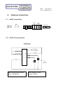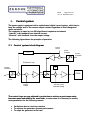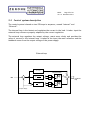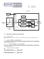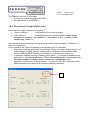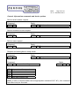
1
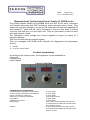
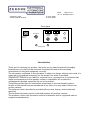
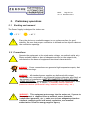
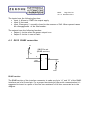
ZENONE Elettronica S.r.l.
Via Nazionale Pianopantano
83036 Mirabella Eclano (AV)
P.I. 02407830641
Tel. 0825449171 Fax 0825407907
DC Power Supplies
AL3000 series
User’s manual
Release xx, November 2011
Firmware version:
DSP version:
Vxx
Vxx
This manual is integrant and essential to the product. Read carefully and completely the instructions and
the warnings herein, they will provide important information regarding safety of operation and
maintenance.
This equipment must be used only for the purpose for which has been designed. Any other utilization is
improper and therefore potentially dangerous. The manufacturer is not responsible for possible damages
caused by improper, incorrect and unreasonable utilization of this equipment.
Any intervention on the equipment, that would cause a change in the structure or in the cycle of operation,
must be performed or authorized by the technical department of Zenone Elettronica.
ZENONE Elettronica S.r.l.
Via Nazionale Pianopantano 83036 Mirabella Eclano (AV)
Tel. 0825449171 Fax 0825407907
[email protected]
www.zenoneelettronica.it
Attention
This manual provides all the necessary information regarding the mode
of operation of AL3000 and AL3000R power supplies series. For the
correct use of this specific equipment it is recommended to refer to the
characteristics data sheet of the power supply, which is an integral part
of this manual.
Caltest Instruments GmbH
Kohlmattstrasse 7 Tel: +49(0)7842-99722-00
D-77876 KAPPELRODECK Fax: +49(0)7842-99722-29
[email protected] www.caltest.de
MUGL
Page 2 of 41
rev. xx November 2011
(Regenerative)1 bidirectional Power Supply AL 3000R series
The power supplies AL3000 and AL3000R series are fast AC/DC static converters
with double conversion and IGBT technology under microprocessor control. They
supply the load with voltage or current at the value that has been set regardless of
the inpedance2) value and the mains fluctuations, they can also draw in energy
from the load and put it on the mains net. They are particularly suited to users
with high dynamic needs.
The information about voltage and current supplied is shown by means of 7
segments displays.
They can be controlled by external signals.
They are equipped with RS485 serial interface for diagnostics and parameters
setting.
1) R model
2) in current control mode
Product presentation
According to the output power, the equipment can be assembled in:
table rack
recessed rack
metal cabinet
Control interface
commands and connections
voltage setting command and visualization:
current setting command and visualization:
logical command for output-on:
selection local/remote commands:
line breaker:
RS485 serial interface:
mains supply:
outputs:
on front panel
on front panel
on front panel
from serial interface
on front panel
on front panel
from cable on the back side (rack version)
on terminal blocks inside the cabinet (heavy
duty cabinet version)
on front panel jacks or bars (rack version)
on terminal blocks inside the cabinet (metal
cabinet version)
MUGL
Page 3 of 41
rev. xx November 2011
emergency input:
auxiliary inputs/outputs
on front panel
on front panel
Front panel
Emergency
Mains line
breaker
V
Voltage
setting
A
Current
setting
Output jacks
Introduction
Thank you for choosing our product. We invite you to read this manual thoroughly
because here you can find the technical characteristics and all the necessary
information for using this equipment correctly.
The information contained in this document is subject to change without notice and it is
expected to be updated exclusively for the product for which is provided.
ZENONE ELETTRONICA is not liable for technical error, printing error or omissions that
might be encountered in this manual; neither is responsible for accidental or
consequential damages caused by the use of its product.
This guide provides specific information related only to the mentioned products.
No part of this manual may be reproduced in any form or by any means without our
written consent.
The software herein described is provided with end user license, unless otherwise
specified.
This technical document version voids and replaces all previous versions.
The products cited in this document could be trademarks and/or registered mark of
respective manufactures.
MUGL
Page 4 of 41
rev. xx November 2011
Summary
1. Preface ............................................................................................ 5 1.1 1.3 1.4 How to use and understand the instructions provided in this manual ............................ 5 Compliance declaration ...................................................................................... 7 Identification label ............................................................................................ 8 2.1 2.2 2.3 2.4 2.5 2.6 2.7 2.8 Working environment ......................................................................................... 9 Precautions ...................................................................................................... 9 Emergency circuit ............................................................................................ 10 Switching the equipment on ............................................................................... 10 Regeneration(only AL3000R models) .................................................................... 10 Regenerator error conditions ............................................................................. 11 Regenerator serial port .................................................................................... 12 Regenerator functional diagram (only AL3000R models) ........................................... 12 3.1 3.2 3.3 3.4 sensing.......................................................................................................... 13 Inputs ........................................................................................................... 14 Outputs ......................................................................................................... 14 Communication port ......................................................................................... 14 2. Preliminary operations ........................................................................ 9 3. Inputs / Auxiliary outputs ................................................................... 13 4. Power output................................................................................... 15 4.1 Command type selection ................................................................................... 15 4.2 Starting the output of power .............................................................................. 15 4.3 Setting the voltage and current values ................................................................. 15 4.4 Setting the simulated resistance ......................................................................... 16 4.5 Maximum power limitation ................................................................................ 16 4.5.1 Ramps up and down .................................................................................. 16 4.5.2 Separate control of the current limits (supply / absorption) .............................. 16 4.6 Visualization of values entered .......................................................................... 17 4.7 Visualization of measurements ........................................................................... 17 5. Maintenance instructions ................................................................... 17 6. External connections ......................................................................... 18 6.1 6.2 6.3 6.4 MAIN connections............................................................................................. 18 DB15 I/O connections ........................................................................................ 18 DB15 RS485 connection .................................................................................... 20 DB15 analog connections ................................................................................... 21 9.1 9.2 9.3 9.4 9.5 Control system block diagram ............................................................................ 24 Control system description ................................................................................ 25 Parameters definition and function ..................................................................... 26 Fine-tuning procedure for the control system ......................................................... 27 Technique for fine tuning the loops ..................................................................... 28 7. Error and faults signals ..................................................................... 22 8. Converter diagram............................................................................ 23 9. Control system................................................................................. 24 10. Software PWMutil .......................................................................... 31 11. AL Manager software ...................................................................... 33 10.1 10.2 11.1 12. Connection to a PC........................................................................................ 31 Connection through digital card ....................................................................... 32 Software installation .................................................................................... 33 Communication protocol VXX ........................................................... 34 MUGL
Page 5 of 41
rev. xx November 2011
1.
Preface
1.1
How to use and understand the instructions provided in this
manual
In this manual have been used conventional keys to simplify and standardize the
utilization and the control of our generators.
In this manual you can find also functions that might not be present on the
equipment you have purchased; nevertheless proper information will tell you about
eventual limitations.
This solution has been chosen for clarity and to better evaluate the functional
characteristics available on all our products.
1.2 Safety instructions
The following notes or graphic symbols list a series of instructions essential for the
correct use of the equipments. Such information could be found, in graphic form,
also on the equipment or used in the manual to focus the attention on the specific
issue. It is highly recommended to read such instructions carefully before
equipment installation.
Do not install the equipment in environments with temperatures different
from those allowed
Do not expose the equipment to direct sun light
Do not pour any kind of liquids on the Equipment.
In case of fire, use foam, CO2 or dry chemicals fire-extinguishers
MUGL
Page 6 of 41
rev. xx November 2011
Attention
The lightning symbol within a triangle is a warning symbol that indicates
the presence of “dangerous voltages” inside the equipment with risk of
electric shock.
!
The exclamation mark within a triangle is a caution symbol that
indicates the presence of important additional information for the
correct use of the equipment.
The empty triangle it is a caution symbol that indicates a danger of
equipment damage if improperly used.
The text that follows this symbol gives information, recommendations
or other particular instructions for the correct operation of the
equipment.
The text that follows this symbol gives information, recommendations
or other particular instructions in order to avoid danger and/or injury
to personnel.
A proper disposal of the shipment packing is recommended.
MUGL
Page 7 of 41
rev. xx November 2011
1.3
Compliance declaration
MANUFACTURER DECLARATION OF CONFORMITY
The Zenone Elettronica Power Supplies :
AL3000 and AL3000R
are herewith confirmed to comply with the requirements set out in the Council Directive on the
Approximation of the Law of Member States relating to:
- Electromagnetic Compatibility, Directive 2004/108/EEC
- EN 61000-6-1 - CEI EN 61000-6-1 (2° ed. 2007-10)Electromagnetic compatibility
(EMC) - Part 6-1: Generic standards - Immunity for residential, commercial and
light-industrial environments "
- EN 61000-6-3 - CEI EN 61000-6-3 (2° ed. 2007-11)
Electromagnetic compatibility (EMC) - Part 6-3: Generic standards - Emission
standard for residential, commercial and light-industrial environments
EN 61326-1 :2006
Electrical equipment for measurement, control and laboratory use - EMC
requirements - Part 1: General requirements
- Low Voltage Equipment Directive (2006/95/EEC) and EN61010-1 (“Safety of
Electrical Measuring Apparatus”)
Mirabella 01-03-2011
Zenone Eletrronica S.r.l.
Luigi Zenone
Copyright Acknowledgement: EN publications are subject to the Copyright of IEC.
MUGL
Page 8 of 41
rev. xx November 2011
1.4
Identification label
Each equipment is identified by the following label.
We invite you to consider the data shown in it as essential for product traceability, and
to communicate them for eventual request for assistance.
MUGL
Page 9 of 41
rev. xx November 2011
2.
Preliminary operations
2.1 Working environment
The Power Supply is designed for indoor use.
+ 5 °C °
!
+ 40 °C
Place the device on a suitable support or on a plane surface for good
stability. Be sure that proper ventilation is allowed and no objects obstruct
the ventilation openings.
2.2 Precautions
Operate the equipment at its rated mains voltage, on earthed outlet only.
Fasten suitable cables or bars of adequate section on the output bolts,
calculated on the bases of equipment functional characteristics.
WARNING: Power connections can generate high temperature spots, that
could cause burnings.
WARNING: All standard power supplies are delivered with output
FLOATING, not connected to any potential (unless otherwise specified); at
the moment of installation MUST BE CONNECTED TO GND OR TO ANY
OTHER POTENTIAL. Maximum allowed voltage on the output bolts, when
not connected to earth, is 300VAC. If necessary connect eventual
protection devices (differential relay, isolation control relay, etc.)
!
WARNING : This equipment puts energy into the mains net, if power to
the equipment is supplied from an external source (batteries,
independent generator, etc.), make sure to have adequate protection
elements complying with local actual regulations, and eventual
authorizations from the energy supplier agency.
MUGL
Page 10 of 41
rev. xx November 2011
2.3 Emergency circuit
The AL3000 series is equipped with an emergency circuit that provides to opening the
main breaker
The opening condition are:
• Pressing the emergency button
• Opening of doors
• Main power failure
• Opening external circuit
The emergency circuit is always powered, even when the main breaker is off
2.4 Switching the equipment on
Connect the power supply to the power mains, it is recommended to follow the
instructions given on the equipment (or in the attached sheet) regarding voltage,
frequency and earth connection, then turn on the power switch, that could be located
on the back panel or by the cabinet side depending on the type of equipment.
In some models the power-on command can be part of an external power supply frame.
In some cases the integrated console, keyboard/display, can be connected to the
cabinet by means of an external cable.
At system power-on an self-diagnostic routine tests the most important equipment
functionalities and detects eventual faults (the information are visible with the proper
software).
In case of failure or malfunctions, we must be informed in advance before sending the
equipment to our laboratories.
2.5 Regeneration(only AL3000R models)
The AL3000R power supply series are bidirectional devices, as a matter of fact they can
either supply energy to the load or absorb energy from it; the energy is taken from or is
put on the power mains. This function is accomplished through an extra converter called
REGENERATOR.
In fact it will adjust the DC voltage on an intermediate bus taking it or putting it back
into the network, providing also to put in phase the absorption and the regeneration so
to guaranty a PF >0.95 at Pn.
According to the model, the regenerator block can be either internal to the equipment
or external in a separate unit. The regenerator block, in normal mains network
condition, does not need any setting or adjusting because it works autonomously
controlling the BUS voltage, in some special cases it might be necessary to touch up
some control parameters using the software PWMutil. The power that the equipment is
capable to draw from the load is the same that is capable to supply. The regenerator has
its own electronics with microprocessor that provides the energy management and the
monitoring of all alarms and system parameters.
MUGL
Page 11 of 41
rev. xx November 2011
2.6 Regenerator error conditions
Under error conditions, the regenerator stops the operation and signals the failure by
display on the cards . The cause of the fault can be visualized by error code or means of
the PWMutil program connecting it to the appropriate serial port on the regenerator.
signal
1
2
3
4
5
6
7
8
9
A
B
C
D
E
0
Type error
DC overvoltage
DC undervoltage
Over temperature
IGBT Error (FAULT)
Precharge error
Current limitat
NTC error
CKS error
AC overvoltage
AC undervoltage
HI frequency
LOW frequency
ZC missing
Feedback error
Slave T.OUT
Remedy
MUGL
Page 12 of 41
rev. xx November 2011
2.7 Regenerator serial port
The regenerator is equipped with standard RS485 serial port communication with rate
fixed at 9600
DB9 Pinout
RS485
B
1
A
GND
2
5
2.8 Regenerator functional diagram (only AL3000R models)
Line Input
precharge
DC out
PWM
Modulator
Sync
µP
Control unit
RS485
comm.
serial
MUGL
Page 13 of 41
rev. xx November 2011
3.
3.1
Inputs / Auxiliary outputs
sensing
+ output
+ sensing
Main
power
V
Internal
measurement
Sensing input
Power output
- sensing
- output
Sensing circuit diagram
The sensing circuit has internally resistors that link the senses to the main output in
order to prevent the AL3000 to go to its maximal voltage when the sense line is broken
or accidentally removed.
The resistors are sized that If the sense is broken or removed, the output voltage result:
(Set output voltage X 1.1) circa
If the sensing is reversed the AL3000 will not started and can break the sense
circuit.
MUGL
Page 14 of 41
rev. xx November 2011
3.2
Inputs
The AL 3000 power supplies are equipped with some inputs for the remote control.
function
Emergency
on – off
Voltage command
Current command
3.3
Description
NC contact with no voltage, its opening causes the immediate disengagement
of the line breaker disconnecting the equipment from the mains
NO contact with no voltage, allows to start the power supply from a remote
command
Analog input 0 ÷ 10V, remote command for the output voltage 0 ÷ 100%
Analog input 0 ÷ 10V, remote command for the output current 0 ÷ 100%
Outputs
The AL 3000 power supplies are equipped with some outputs for remote signaling.
function
Run/stop
Alarm
description
PNP digital output, signaling for output on/off
Max 30V 0,5A
PNP digital output, fault signaling
Max 30V 0,5A
3.4 Communication port
The power supply is equipped with a RS484 communication port which allows to connect
a PC for some parameters setting and for the alarm register reading.
The Baud Rate is the transfer speed and is set at 9600.
MUGL
Page 15 of 41
rev. xx November 2011
4.
Power output
4.1 Command type selection
The selection of the command type:
• Front panel
• analog or digital inputs
• serial port
can be done via serial link by means of “AL Manager” software.
4.2 Starting the output of power
After the preliminary operations, connecting the equipment to the mains and to an
eventual load, have been done it’s possible to turn on the power supply acting on
the main switch.
Note: the main switch will not activate if the emergency circuit is open or
the emergency push-button is pressed.
Once the equipment is turned on it’s possible to start the output of power in
following ways:
• With local command; acting on the on-off push-button.
• With remote command; activating the proper input.
• With command from serial port; entering the appropriate string.
Under these conditions the power supply will take immediately the voltage and
current values set.
4.3 Setting the voltage and current values
The setting of voltage and current output can be done:
• With local command; by means of the potentiometers on the front panel
• With remote command; by means of analog signal 0 ÷ 10V
• With command from serial port; by means of appropriate strings
Note: some particular settings are possible only by means of command
from serial port
MUGL
Page 16 of 41
rev. xx November 2011
4.4 Setting the simulated resistance
The power supply can simulate a resistance in the output such that given a set
voltage V:
The output voltage is dynamically reduced by the value R (set) x I (circulating) in case
of power output, is dynamically increased by the value R (set) x I (circulating) in case
of absorption.
The resistance setting is expressed in OHM with respect to the maximum value and
has a 1mOHM resolution. It can be done through the analog input (if selected) or
through a serial string.
If resistance is selected on analog input, is possible to set the maximum value
corresponding at 10V by software “GESMD”
Note: with simulated resistance and some types of reactive loads
instabilities might be triggered.
4.5 Maximum power limitation
The power supply can work with constant power operation. To use this function first
adjust voltage and current limits within which you want to work, then set the value of
maximum power output.
In these conditions when the load will require more power than that set, the voltage will
be automatically decreased so that the P (out) ≤ P (set). In the case of regeneration the
voltage is increased.
The setting of power is expressed in W with respect to the value of the specification
sheet and has a resolution of 1W. It can be done through analog input (if selected) or
through serial string.
4.5.1 Ramps up and down
Ramps up and down allow a "sweet" start of the output voltage avoiding overshoot.
Ramps can be set at “0” or from 100mS up to 10S.
Ramps have effect only during the transition OFF-ON.
The setting of ramps can be done through serial interface.
4.5.2 Separate control of the current limits (supply / absorption)
You can independently set the maximum limits of positive and negative current. In this
way the power supply will follow the current limitation set by the potentiometer or
other input up to the maximum limit set for this polarity, for any other value over the
limit the current will be cut to the limit.
This function is used to set profiles of current asymmetrical between supply and
absorption.
The two parameters are settable by serial link.
MUGL
Page 17 of 41
rev. xx November 2011
4.6 Visualization of values entered
In stand-by it’s possible to visualize on the displays the voltage and current values
simply pressing the “F1” push-button
“F1” pressed = visualization of voltage and current entered
“F1” released = off
4.7 Visualization of measurements
While the output is on the power supply shows on the displays the voltage and current
outputs.
Pressing “F1” it’s possible to visualize voltage and current setting.
5.
•
•
•
Maintenance instructions
Check periodically the air vents, clean them or change the filter;
Check the fans efficiency.
Check periodically the bolts of the connections between the power outputs and
the external circuit under test.
MUGL
Page 18 of 41
rev. xx November 2011
6.
External connections
6.1 MAIN connections
Output
DB15
Line
input
EARTH bar
6.2 DB15 I/O connections
DB15 Pin Out
I/O section
Vout 24Vcc
max 100mA
9
in1
1
in2
2
11
3
12
0V
+24V
10
Out 1
Out 2
4
24V
(20-30V)
Max current sink from each
input: 4mA@24Vdc
Max current for each
output: 500mA
MUGL
Page 19 of 41
rev. xx November 2011
I/O section
The I/O section of the interface connector is made of:
• 2 Inputs “PNP” type at 24V (Pin 1 and 2)
• 2 outputs “PNP” type at 24V (Pin 11 and 12)
• 1 24V supply output limited at 100 mA max
• 2 Pins assigned for a 24V supply (4=GND e 10=VCC).
MUGL
Page 20 of 41
rev. xx November 2011
The inputs have the following function:
• Input 1: Allows to START the output supply
• Input 2: Not used
• Input “Emergency”: normally closed to the common of 24V. When opened causes
the disengagement of the line breaker.
The outputs have the following function:
• Output 1: Active when the power output is on.
• Output 2: Active in case of fault.
6.3 DB15 RS485 connection
5V
DB15 Pin-out
(RS485 section)
1K
A
5
GND
13
B
6
1K
GND
RS485 section
The RS485 section of the interface connector is made up of pin “A” and “B” of the RS485
interface and of a Ground pin. For a proper functioning of the serial communication it’s
suggested to insert in a point of the line two resistance of 1K ohm connected as in the
diagram.
MUGL
Page 21 of 41
rev. xx November 2011
6.4 DB15 analog connections
DB15 Pin-out
(Analog section)
GND
6
AIN1_P
AIN1_N
7
14
8
15
AIN2_N
AIN2_P
ANALOG section
The Analog section of the interface connector is made of pin:
• AIN1_P and AIN1_N of the Analog input 1 (Pin 14 and 7)
• AIN2_P and AIN2_N of the Analog input 2 (Pin 15 and 8)
• Reference ground GND (Pin 6)
They are two balanced inputs that can take a maximum voltage of +/- 10V with respect
to GND.
Their function, when enabled by appropriate command via RS485, is to set the Voltage
(Input 1) and the Current (Input 2).
MUGL
Page 22 of 41
rev. xx November 2011
7.
Error and faults signals
The converters are equipped with self-diagnosis routine, in case of anomalous event
they stop the power output and show an error message.
Signal
Cause
DSP X FAIL
Communication error between
the central processor and the
DSP shown by nr. X
Generic error
FAIL XX
signal
Type error
1
DC overvoltage
2
DC undervoltage
3
Over temperature
4
5
6
7
8
9
A
B
C
D
E
0
IGBT Error (FAULT)
Precharge error
Current limitat
NTC error
CKS error
Remedy
Shut off and turn on the equipment; if the
error remains contact the assistance
See the display on cards or connect a PC to
the equipment and by means of the
software “PWMutil” check the table below
Remedy
Check the mains voltage, the presence of all three phases and
that the regenerator works properly.
Check the mains voltage, the presence of all three phases and
that the regenerator works properly.
Shut off the equipment and wait a few minutes. If the phenomenon
repeats check the air vents and the operation of the fans.
Contact the assistance
Check the precharge relay.
Check the load or the parameters settings.
Contact the assistance.
Feedback error
Slave T.OUT
If the fault remains, contact the assistance.
MUGL
Page 23 of 41
rev. xx November 2011
8.
Converter diagram
Output
BUS DC
Input
PWM
Modulator
µP
Serial
Command I/O
Control Unit
Functional diagram
Power supply/load section
MUGL
Page 24 of 41
rev. xx November 2011
9..
Control system
The power supply is equipped with a sophisticated digital control system, which has to
keep the voltage and/or the current output constant regardless of load change and
mains variations.
The regulation is based on two PID algorithms in sequence and named:
“Internal” with feedback from internal current,
“External” with feedback from the output voltage.
The following figure shows the principle of operation
9.1 Control system block diagram
Output
current
Power
limitation
Current
regulation
External Loop
F.F.
Voltage
reference
REF1
+
REF
+
-
REF2
PWM
-
Ramp
Output
voltage
Internal current
Internal Loop
The control loops are pre-adjusted in production to achieve a good compromise
between speed and stability for most loads, in some cases it is necessary to modify
some parameters for the following reasons:
•
•
•
Oscillations due to a load too reactive
To enhance the generator dynamic performance
To adapt the generator to the load
MUGL
Page 25 of 41
rev. xx November 2011
9.2 Control system description
The control system is based on two PID loops in sequence, named “Internal” and
“External”.
The internal loop is the fastest and regulates the current in the load. It takes input the
external loop reference properly adapted by the current regulation.
The external loop regulates the output voltage, reacts more slowly and provides the
value of current to the internal loop. It takes at the input the main reference and the
feedback comes from the output voltage of the power supply.
External loop
Integral limitation
+
1
REF
+
+
+
1
Output voltage
Derivative limitation
REF1 to internal
loop
MUGL
Page 26 of 41
rev. xx November 2011
Internal loop
Offset
F.F.
Current
limiter
Integral limitation
+
+
1
+
REF1 (from
external loop)
Amplitude
REF2
+
+
-
To
modulator
1
Internal current
Derivative limitation
From voltage
control
9.3 Parameters definition and function
range 0 ÷ 10000
It’s the proportional gain of the regulation loop (it causes the output to change according to the input
error)
Kp:
Ti:
range dt ÷ 32000µS; 0 = integral disabled
It’s the integration time of the regulation loop in microseconds, can be applied directly or multiplied by
the parameter Kp (causes the output to change with a speed proportional to the error, sets the regulation
point canceling out the offset).
Td:
range dt ÷ 32000µS; 0 = derivative disabled
It’s the derivative time of the regulation loop in microseconds, can be applied directly or multiplied by
the parameter Kp (causes the output to change proportionally to the rate of change of the input, reduces
the system response time).
dt
machine cycle time not changeable.
Positive integral limitation:
range 0 ÷ 100%
It’s the maximum value the variable integral can take
Negative integral limitation:
range 0 ÷ 100%
It’s the minimum value the variable integral can take
MUGL
Page 27 of 41
rev. xx November 2011
Positive derivative limitation:
range 0 ÷ 100%
It’s the maximum value the variable derivative can take
Negative derivative limitation:
range 0 ÷ 100%
It’s the minimum value the variable derivative can take
F.F. Feed forward
range 0 ÷ 20
It’s the anticipation value on the current output, is used to speed the voltage recovery during the load
variations.
9.4 Fine-tuning procedure for the control system
Note: To change the control parameters it’s necessary to have a PC connected to the serial port of
the console and the software program “PWMutil”. (Look at paragraph “PWMutil software”)
The following paragraph provides only a guide for the fine tuning of the PID regulation
loops since in many cases a unique rule it’s not applicable and regulations are made on
the bases of personal experience.
Note:
Eventual parameters modifications must be done by specialized
personnel only because these modifications could cause malfunctions and/or
generator damages.
Note:
Before making any change to the regulation parameters it’s
advisable to take note of the existing parameters so to restore the initial
setup.
In most cases, in particular when the equipment must be adapted to the load, it’s
sufficient to make slight changes to some parameters following simple rules:
In case of sever capacitive load, lower the Kp coefficients and increase the
integration time Ti.
In case of sever inductive load, increase the Kp coefficients and lower the
integration time Ti.
MUGL
Page 28 of 41
rev. xx November 2011
9.5 Technique for fine tuning the loops
The fine tuning of the PID loops must be done in two phases, first the internal one and
then the external.
In order to fine tune and verify the dynamic performances of the generator, it’s better
to set the references with an external generator connected to the proper input, using a
square waveform with the following parameters:
Frequency > 0 < 50Hz
Amplitude 0 ÷ V <5V
or have an external dynamic load
Under these conditions freeze the external loop and adjust the parameters Kp, Ti and Td of the internal loop to get maximum performance.
Once the internal loop has been fine tuned, the parameters Kp, Ti and Td of the
external loop can be adjusted so to optimize the global performance.
Ideal system response to a step
function
MUGL
Page 29 of 41
rev. xx November 2011
Step function response varying Kp with Ti constant
Step function response varying Ti with Kp constant
MUGL
Page 30 of 41
rev. xx November 2011
Step function response with Kp too high
Step function response with Kp and Ti too small
MUGL
Page 31 of 41
rev. xx November 2011
10. Software PWMutil
The “PWMutil” software is compatible with WINDOWS XP systems and allows to set up
some important parameters of the power supply; it must be installed on a suitable PC
and executed.
Such software is designed to set up the parameters of different equipment types we
produce, therefore it’s possible that are displayed some parameters that have no
function for this specific power supply.
10.1 Connection to a PC
The equipment must be connected to the PC trough the serial port of the console by
means of the specific cable.
After the connection has been done and the program PWMutil is executed, the following
mask will appear:
By means of the menu “Set” it’s possible
to select the parameters for the serial
link:
PC port and baud-rate. In this case the
baud-rate must be 9600
Alarm Box
Output parameters
1
Set parameters
2
MUGL
Page 32 of 41
rev. xx November 2011
The PWMutil can work in two ways:
• directly on modulation board (ZEL1004)
• through digital card (ZEL0901)
10.2 Connection through digital card
Enter the following parameters in position “2”:
• “Device Address”:
serial address of the power supply
• “DSP Address”:
serial address of the power module (if more power
modules are present: 1 for module 1, 2 for module 2, etc..; in case of one
module only, enter 1)
Once the parameters have been set-up as shown above, push the button “Connect” to
start the connection.
In this situation the mask will appear as shown above and it’s possible:
• display the machine state with the readings of Output voltage, Output current, AC
mains voltage, DC BUS voltage, temperature of heat sink and the state of the
alarms. With the RESET button it’s possible to reset some stored alarms.
• In quadrant 1 appear the box “Enabe control panel”, if checked is possible to set
parameter in the appropriate boxes. This if the power supply is in off state (this
function excludes all other controls front panel, analog input, ecc)
• By means of the button “PIDs parameter” to step into the next mask where the
PWM parameters are shown and could eventually be changed.
1
MUGL
Page 33 of 41
rev. xx November 2011
The sampling timing “dt” is shown at point “1”.
In order to change any parameter just overwrite it and press ENTER on the keyboard.
The button “REFRESH” provides an over-reading of the parameters stored in the memory
module.
!
Warning: in case of more power modules, the regulation parameters must be
the same for each module.
11. AL Manager software
The “AL Manager” software allows the total control of the power supplies AL2000M and
AL2000BX series.
AL Manager software can handle up to 32 power supplies AL2000 series.
11.1 Software installation
The “AL Manager” software is compatible with Windows XP and is supplied in a
compressed package.
For the installation just click over the proper icon and accept the license agreement
terms.
The “AL Manager” program is supplied with free license for the ZENONE ELETTRONICA
equipments users and its disclosure it’s forbidden.
Note: ZENONE ELETTRONICA disclaims any liability for incompatibilities or conflicts
with other software and operating systems.
MUGL
Page 34 of 41
rev. xx November 2011
12. Communication protocol VXX
Communication protocol
It’s possible to communicate with the device (send commands and get replies) by means
of the RS485 serial interface, according to a half-duplex communication protocol.
The settings of the communication port is:
Device address:
Baud-rate:
Number of bits:
Stop bit:
Parity:
from 1 to 32
9600 b/s
8
1
None
(assigned with appropriate software)
Each command and each reply are preceded by a start (STX) and the address (IND) of the
device we intend to communicate with, followed by a stop (ETX) and a checksum
(CKSUM) for the data correctness verification.
STX IND Command or reply ETX CKSUM
STX
IND
=
=
ETX
CKSUM
=
=
Start character, Hexadecimal value
0x02
Device address, added to the hexadecimal value 0x80
(ex. Address 1 = character 0x81)
Stop character, Hexadecimal value
0x03
Control checksum, it’s a character sum of all characters of the command,
Inclusive of STX and ETX characters, module 256.
Each command that carries a parameter receives a reply with a result character (ESI)
that can have the following values:
“0” = Command executed.
“1” = Command not executed.
MUGL
Page 35 of 41
rev. xx November 2011
General information commands and device options
Device serial number request
Command
0x10 "S"
Reply
0x10 "S" Serial number
Device firmware version request
Command
0x10 "F"
Reply
0x10 "F" Firmware version
Device name request
Command
0x10 "N"
Reply
0x10 "N" Device name
Request and setting device setup mode
Command
0x10 "M"
Command
0x11 "M" Setup mode setting
Reply
0x10 "M" Setup mode
Reply
0x11 "M" ESI
"0" Setup and start from panel
"1"
"2"
"3"
“4” Setup and external start
Note: In case of remote mode (look at appropriate command 0x15 “M”), this command
has effect only for the start.
MUGL
Page 36 of 41
rev. xx November 2011
Commands for test main setup
Request and setting voltage value
Command
0x12 "M"
Reply if IDX ok
0x12 "M" IDX
IDX
UMIS Voltage value *
Reply if IDX not ok
0x12 "M"
ESI
Command
0x13 "M"
IDX
Reply
0x13 "M" ESI
IDX UMIS Voltage value *
= 0x81 (Fixed value)
UMIS = “1” (Fixed value)
* For the allowed ranges refer to equipment specifications
Request and setting current value
Command
0x12 "E"
Reply if DX OK
0x12 "E" IDX
IDX
UMIS Current value *
Reply if IDX not OK
ESI
0x12 "E"
Command
0x13 "E"
IDX
UMIS Current value *
IDX
= 0x81 (Fixed value)
UMIS
= “1” (fixed value) Ampere
* For the allowed ranges refer to equipment specifications
Reply
0x13 "E"
ESI
MUGL
Page 37 of 41
rev. xx November 2011
Request and setting maximum power value
Command
0x12 "X2"
Command
0x13 "X2" Power
Reply
0x12 “X2” Power
0x13
Reply
ESI
Power is in Watt from: 0 to f.s.
Request and setting internal resistance
Command
0x12 "X1"
Reply
0x12 "X1" Resistor
Command
0x13 "X1" Resistor
Reply
0x13 ESI
Resistor is in Ohm from: 0.001 to 1000
MUGL
Page 38 of 41
rev. xx November 2011
Request and setting reference sources.
Command
0x20 "C"
Reply
RIF
0x20 "C" RIF
SRC
Reply if RIF not OK
0x20 "C" ESI
Command
0x21 "C"
RIF
Reply
0x21 "C" ESI RIF2
SRC
Reference values and associated source
RIF
“0”
“1”
“2”
“3”
“4”
“5”
Voltage
Current
Source of START
Not used
RESISTANCE reference
POWER LIMITATION reference
“0”
SRC
“1”
“2”
Pot. 1
Pot. 2
Panel
Pot. 2
Fixed 0 ohm
Fixed MAX
Input AN1
Input AN2
Input IN1
Input AN2
Input IN1
Input AN2
From serial
From serial
From serial
From serial
From serial
From serial
Nota: This command ESI can take also value “2”. In this case means that SRC you want
to use is already used by the reference RIF2.
Request end sending RAMP timing
Command
0x12 "T"
Reply if IDX OK
IDX UMIS RAMP timing (ms)
0x12 "T"
IDX
Reply if IDX not OK
0x12 "T"
ESI
Command
0x13 "T"
IDX
UMIS RAMP timing (milliseconds)
IDX
= 0x81 (Fixed value)
UMIS
= “0” (Fixed value)
Reply
0x13 "T"
ESI
MUGL
Page 39 of 41
rev. xx November 2011
Request and sending Ramp mode
Command
0x12 "R"
Reply if IDX OK
0x12 "R" IDX Mode
IDX
Reply if IDX not OK
0x12 "R" ESI
Command
0x13 "R"
IDX
IDX
Reply
0x13 "R"
Mode
= 0x81 (Valore fisso)
Mode
“0” No ramp
“1” Linear ramp
Commands for reading the actual values
Reading the actual state
Command
0x14 “E”
Reply
0x14
Test state
"0" Halt
"1" Running
“2”
“3”
“4”
“5”
“6” Fail (failure or malfunction)
“7”
“A”
“E” State or test result
ESI
MUGL
Page 40 of 41
rev. xx November 2011
Reading the actual voltage
Command
0x14 “M”
FA
FA
Reply
0x14
“M” UMIS Actual value
Necessary in the three-phases devices.
Select the phase to read (“1”,”2”,”3”), if omitted
it means “1”
UMIS
“0”
“1”
Millivolt
Volt
Reading the actual current
Command
0x1 “S”
4
FA
UMIS
“0”
“1”
FA
Reply
0x14
“S”
UMIS Actual value
Necessary in the three-phases devices.
Select the phase to read (“1”,”2”,”3”), if omitted
it means “1”
Millivolt
Volt
Milliampere
Ampere
Reading the remote connection state
Command
0x14 "L"
Connection state
“L”
Not ACTIVE
“R”
Active
Reply
0x14
"L" Connection state
MUGL
Page 41 of 41
rev. xx November 2011
Test Start and Stop commands
Enables remote mode
Command
0x15 "M"
Mode
Reply
0x15 "M" ESI
Remote mode
Not active
“L”
Active
“R”
In “Remote” mode the output values are defined via SERIAL link. The start can be given
from SERIAL link or from PANEL/EXTERNAL according to the appropriate command
(0x11 “M”).
Supply start
Command
0x15 "R"
Reply
0x15 "R" ESI
Note: It’s possible to start the supply only if in remote mode and start from selected
PANEL/EXTERNAL.
The positive result of the command means that it was accepted but, in order to be sure
the start has taken place, it’s necessary to read the device state (Command 14E).
Supply stop
Reply
0x15 "S"
Command
0x15 "S"
ESI
Note: It’s possible to stop the supply only if in remote mode and stop from selected
PANEL/EXTERNAL.
The positive result of the command means that it was accepted but, in order to be sure
the stop has taken place, it’s necessary to read the device state (Command 14E).
Address assignment
Command
0x15 "A"
IND
Reply
0x15 "A" ESI