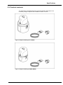
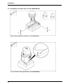
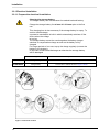
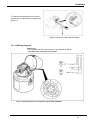
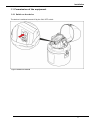
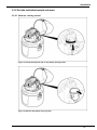
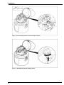
1
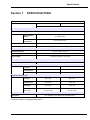
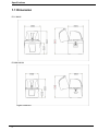
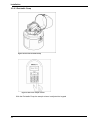
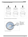
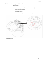
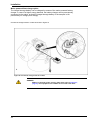
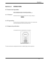
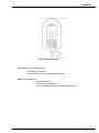
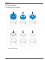
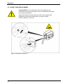
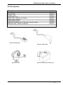
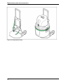
User Manual
for
Portable Sampler
P6 L / P6 Mini MAXX
P6 L
P6
02500xxE
P6 Mini MAXX
January 2015
© MAXX GmbH, 2014. Alle Rechte vorbehalten. Gedruckt in Deutschland
Access code for programming and settings
Password:
Your Password:
6299
Table of Contents
Section 1
SPECIFICATIONS ............................................................................................ 5
1.1 Dimension ...................................................................................................................... 6
Section 2 GENERAL INFORMATION................................................................................. 7
2.2 General Information ....................................................................................................... 8
2.2.1 Areas of application ..................................................................................................... 8
2.3 Product contents ........................................................................................................... 9
Section 3
INSTALLATION ................................................................................................. 10
3.1.1 Required Tools ............................................................................................................ 11
3.1.3 Installation location (P6 L and P6 MINI MAXX) ......................................................... 12
3.2 Electrical Connections ................................................................................................. 13
3.2.1 Electrical Installation ..................................................................................................... 14
3.2.1.1 Prepare the electrical installation .............................................................................. 14
3.2.1.2 Wiring diagram ......................................................................................................... 15
3.2.1.3 Connection to a PC .................................................................................................. 16
3.3 Commission of the equipment ...................................................................................... 17
3.3.1 Switch on the device ..................................................................................................... 17
3.3.1. Tube connection and Positioning of the tubes ............................................................ 18
3.3.2 Set the individual sample volumes ............................................................................... 19
3.3.2.1 Vacuum –dosing vessel ............................................................................................. 19
3.3.2.2 VAR Dosing vessel for flow-proportional sampling (Option) .................................... 21
3.3.2.3 Peristaltic Pump ......................................................................................................... 22
3.3.2.3 Calibration of the Peristaltic Pump ............................................................................. 23
3.3.3 Remove the top part of the housing ........................................................................... 24
3.3.5 Prepare the sample bottles......................................................................................... 25
3.3.6 Attach the top part of the housing ............................................................................. 26
3.3.7 Connect the equipment to the mains ......................................................................... 27
Section 4
OPERATION....................................................................................................... 29
4.1 Control unit operation ................................................................................................... 29
4.1.1 Password..................................................................................................................... 29
4.1.2 Programming ............................................................................................................... 29
4.1.3 Keyboard layout/function ............................................................................................ 29
4.2 Normal operation .......................................................................................................... 32
4.2.1 Replace the sample bottles ........................................................................................ 32
Section 5 MAINTENANCE AND CLEANING ........................................................................ 34
5.1 Maintenance work ......................................................................................................... 34
5.1.1 Desiccant replacement ............................................................................................... 34
5.2 Cleaning ........................................................................................................................ 39
5.2.1 Clean the housing and distribution unit ...................................................................... 39
3
5.2.2 Clean the dosing vessel ............................................................................................... 40
5.3 Troubleshooting ............................................................................................................. 42
5.3.1 Change the fuse ........................................................................................................... 42
Section 6 REPLACEMENT PARTS AND ACCESSORIES ................................................................ 44
6.1 Spare parts - P6 ............................................................................................................ 44
6.1.1 Spare parts P6 Peristaltic Pump ................................................................................ 44
6.1.1 Spare parts P6 Vacuum Dosingsystem ..................................................................... 45
6.2 Accessories ................................................................................................................... 47
Section 7
WARRANTY AND LIABILITY ........................................................................... 49
List of Figures ...................................................................................................................... 50
4
Specifications
Section 1
SPECIFICATIONS
TECHNICAL SPECIFICATION
P6 MINI MAXX
P6 L MAXX
Electric
Power supply,
With integrated
battery
12 V-7,5 Ah (DC)
With optional
power pack
110–230 V/50–60 Hz.
Rating
8 AT
Power consumption
Peristaltic Pump: approx. 70VA / Vacuum System approx. 15VA
Environment
Medium temperature
0 to 40 °C [32 to 104 °F]
Ambient temperature
0 to 50 °C [32 to 113 °F]
Suction height
6,5 m [20 ft], optional < 8 m [26 ft]
General specifications
Maintenance requirements
Maintenance-free
Weight
Top part
Bottle
compartment
Complete
aprox. 9kg
aprox. 15kg
Top part
400 x 333
500 x 377
Bottle
compartment
400 x 310
500 x 415
Complete
400 x 605
500 x 740
90° 400 x 710
110° 400 x 685
90° 500 x 843
110° 500 x 819
Dimensions (H X D) in mm
With lid opened
(90° / 110°)
Certification
Certification
CE, sampling in accordance with ISO 5667-2/3-10
These are subject to change without notice
5
Specifications
1.1 Dimension
P6 L MAXX
P6 MINI MAXX
Figure 1 Dimension
6
Specifications
Section 2 GENERAL INFORMATION
2.1 Safety information
Please read this entire manual before unpacking, setting up, or operating
this equipment. Pay attention to all danger and caution statements. Failure to
do so may result in personal injury or damage to the instrument.
To ensure that the protection provided by this equipment is not impaired,
do not use or install this equipment in any manner other than that
specified in this manual.
2.1.1 Use of hazard information
DANGER
Indicates a potentially or imminently hazardous situation which, if not avoided, will
result in death or serious injury.
WARNING
Indicates a potentially or imminently hazardous situation that, if not avoided, could
result in death or serious injury.
CAUTION
Indicates a potentially or imminently hazardous situation that could result in
minor or moderate injury.
Important note: Information that requires special
emphasis. Note: Information that supplements
points in the main text.
2.1.2 Precautionary labels
Read all labels and tags attached to the instrument. Failure to do so may
result in personal injury or damage to the instrument. A symbol, if noted
on the instrument, will be included with a danger or caution statement in
the manual.
This symbol, if noted on the instrument, references the user manual for
operation and/or safety information.
This symbol, when noted on a product enclosure or barrier, indicates that a
risk of electrical shock and/or electrocution exists.
This symbol may appear on the product and indicates the need for protective
eye wear.
7
Specification
This symbol may appear on the product and identifies the connection point
for the protective ground.
When this symbol appears on the product, it identifies the location of a fuse
or a current limiter.
Electrical equipment marked with this symbol may not be disposed of in European domestic or
public disposal systems after 12 August 2005. In conformity with European local and national
regulations (EU Directive
2002/96/EC), European electrical equipment users must now return old or end-of-life equipment
to the manufacturer for disposal at no charge to the user
Note: For return for recycling, please contact the equipment manufacturer or supplier for
instructions on how to return end-of-life equipment, manufacturer-supplied electrical
accessories, and all auxiliary items for proper disposal.
2.2 General Information
2.2.1 Areas of application
The equipment is used for sampling aqueous liquids with a temperature of 0
°C to 50 °C
(refer to Section 1 Specifications, page 5).
2.2.2 Functional description
The equipment provides temporary storage for liquids of a specified volume so
that they can be analyzed.
8
Specifications
2.3 Product contents
The equipment is supplied with a tube and brief operating instructions. The
necessary charger is optional and available in IP20 or in IP 65.
Figure 2 Scope of delivery (P6 L MAXX)
Figure 3 Scope of delivery (P6 MINI MAXX)
9
Installation
Section 3
INSTALLATION
DANGER
Only qualified experts should conduct the tasks described in this section.
DANGER
Select an appropriate installation location for the instrument.
Plan out the mechanical mount, before positioning poles or drilling
holes. Make sure the mount has a sufficient bearing capacity. The dowels
must be selected and authorized according to the condition of the wall.
The manufacturer shall accept no liability if the instrument is
installed incorrectly.
Plan how to lay cables and tubes and their path in advance. Lay the
tubes, data cables and power cables without any bends and so they
do not pose a tripping risk.
Do not connect the electrical supply to the mains if the equipment
has not been wired and fused correctly.
Sufficiently protect the electrical power supply against short circuits.
For the external power supply, always connect a residualcurrent circuit breaker (trip current max.: 30 mA) between
the mains and the system.
If the equipment is to be installed outdoors, switch the overload
protection between mains and system.
Products intended by the manufacturer for outdoor use offer a higher
level of protection against the penetration of liquids and dust. If these
products are connected to a mains outlet with a cable and plug·rather
than a permanently connected cable, the plug and outlet are much more
susceptible to liquid and dust penetration. The operator must
sufficiently protect the plug and outlet against liquid and dust
penetration in accordance with local safety regulations. If the
instrument is to be used outdoors, it must be connected to a suitable
outlet with a protection type of at least IP44 (splash protection).
10
Installation
3.1 Mechanical Installation
DANGER
Select an appropriate installation location for the instrument.
Plan out the mechanical mount·before positioning poles or drilling holes. Make
sure the mount has a sufficient bearing capacity. The dowels must be selected
and authorized according to the condition of the wall.
The manufacturer shall accept no liability if the instrument is installed
incorrectly.
Plan how to lay cables and tubes and their path in advance. Lay the tubes, data
cables and power cables without any bends and so they do not pose a tripping
risk.
Note : For information on installation with optional accessories, refer to the relevant
installation instructions.
3.1.1 Required Tools
Figure 4 Required tools (P6 L and P6 MINI MAXX)
11
Installation
3.1.3 Installation location (P6 L and P6 MINI MAXX)
Figure 5 Select installation location (P6 L and P6 MINI MAXX)
Figure 6 Position the equipment (P6 L and P6 MINI MAXX)
12
Installation
3.2 Electrical Connections
DANGER
Only qualified experts should conduct the tasks described in this section.
DANGER
Do not connect the electrical supply to the mains if the equipment has not been wired and
fused correctly.
Sufficiently protect the electrical power supply against short circuits.
For the external power supply, always connect a residual-current circuit breaker·(trip
current max.: 30 mA) between the mains and the system.
If the equipment is to be installed outdoors, switch the overload protection between
mains and system.
If the mains plug·of the power supply cable·is removed, a suitable double-pole one-way
switch must be installed immediately next to the display unit·with clear labeling for the power
supply.
Products intended by the manufacturer for outdoor use offer a higher level of protection
against the penetration of liquids and dust. If these products are connected to a mains
socket with a cable and plug·rather than a permanently
connected cable, the plug and socket are much more susceptible to liquid and
dust penetration. The operator must sufficiently protect the plug and outlet against
liquid and dust penetration in accordance with local safety regulations. If the
instrument is to be used outdoors, it must be connected to a suitable outlet with a
protection type of at least IP44 (splash protection)
13
Installation
3.2.1 Electrical Installation
3.2.1.1 Prepare the electrical installation
Charging the storage battery
The integral battery is a maintenance-free sealed lead-acid battery.
Charge the storage battery for at least 14 -16 hours prior to the first
use.
This charging time is also necessary if the storage battery is empty. To
avoid a total discharge,
a protective mechanism is built-in which automatically switches off the
device when the voltage
is too low.
The storage battery cannot be overcharged as the battery charger
switches to compensation charge as soon as the battery is fully
charged.
For longer periods of non-use, top up the charge regularly (connect the
battery to the charger).
In any case, avoid a total discharge as otherwise the storage battery
will be damaged
In battery mode
In mains power mode
P6 L
Charge battery
Connect the Y cable as shown in Figure 7.and 8
P6 MINI MAXX
Charge battery
Connect the Y cable as shown in Figure 7 and 8.
Figure 7 connect the Y-cabel
14
Installation
To connect the equipment to the mains,
connect the Y-cable with the charger see
Figure. 8
Figure 8 connect the Y-cabel with the charger
3.2.1.2 Wiring diagram
Please note:
• The assignment of the connections in the illustration below
• The cable color of the label on the cable.
Figure 9 Connection plan for the optional signal cable (0069644)
15
Installation
3.2.1.3 Connection to a PC
The sampler is connected to a PC by means of an 3 m. MiniUSB interface cable (art. No. 0069793)
With the software “maxxware-Connect” it´s possible to read out the data to a PC.
As option is a LAN/WLAN/GPRS-UMTS board for remote communication also available.
Figure 10 Connection to a PC
16
Installation
3.3 Commission of the equipment
3.3.1 Switch on the device
The device is switched on and off by the ON / OFF switch
Figure 11Switch-on and off
17
Installation
3.3.1. Tube connection and Positioning of the tubes
Figure 12 Connect the Intake tube
Positioning of the tubes according to the following installation diagram
A
Figure 13 Installation diagram
18
Installation
3.3.2 Set the individual sample volumes
3.3.2.1 Vacuum –dosing vessel
1
Figure 14 Unlock the bayonet cap on the plastic dosing vessel
1
Figure 15 Remove the plastic dosing vessel
19
Installation
Figure 16 Cut the dosing tube to set the sample volume
Figure 17 Assemble the plastic dosing vessel
20
Installation
3.3.2.2 VAR Dosing vessel for flow-proportional sampling (Option)
Figure 18 Unit with the VAR Sensors (optional)
Note: The accuracy is only
guaranteed if the system was
previously calibrated for the
sampling site (see
Programming Manual ->
"calibration“)
ΔP = 0 hPa/bar
The flow-proportional dosing
vessel (VAR) can only be
used,if there is
NO counter pressure!
Figure 19 Calibrate the flow-proportional dosing vessel in the “Settings”Menu
With the VAR Dosing vessel, the sample volume is adjusted via keypad
21
Installation
3.3.2.3 Peristaltic Pump
Figure 20 Unit with Peristaltic Pump
Figure 21 Set of the sample volume
With the Peristaltic Pump the sample volume is adjusted via keypad
22
Installation
3.3.2.3 Calibration of the Peristaltic Pump
Figure 22 Calibrate the Peristaltic Pump for flow-proportional sampling
Note: The accuracy is only guaranteed if the system was previously calibrated for
the sampling site (see Programming Manual -> “Settings” "calibration“)
23
Installation
3.3.3 Remove the top part of the housing
1
Figure 23 Remove the top part of the housing
24
Installation
3.3.5 Prepare the sample bottles
Figure 24 Place the empty bottles into the bottle compartment
Note:
At the bottom of the lower
part is the position for
bottle No. 1 marked
together with the filling
direction, thus you can
assign the bottles with the
sample cycle.
Figure 25 Position for bottle No. 1
25
Installation
3.3.6 Attach the top part of the housing
Figure 26 Attach the top part of the housing
26
Installation
3.3.7 Connect the equipment to the mains
Make sure that,
·
The equipment has been fully prepared for commissioning,
·
The data on the type plate corresponds to the data relating to the mains
power supply ( P6 L and P6 MINI MAXX in in connection with the
charger and Y -plug 0069742),
·
The correct plug has been attached or the direct wire has been
implemented correctly
·
The equipment can be put into operation without any risks
Figure 27 Rating label
27
Installation
Mains powered float charge option
The integral storage battery can be charged by means of the mains powered battery
charger. In case of a higher energy demand, the battery charger can be permanently
connected to the mains, so that the integral storage battery of the sampler is left
permanently on charge (float charge).
Connect the charger with the Y-cable as shown in Figure 27
A
Figure 28 Connect the charger with the Y-cable
DANGER
Make sure that the power supply, cable (also refer to Figure 27,
page 27) and equipment are suitable for use with each other..
28
Operation
Section 4
OPERATION
4.1 Control unit operation
All the equipment functions are software-controlled.
See the detailed description in the Programming Manual“
4.1.1 Password
Default Password to program sampler and to change settings is
6299
4.1.2 Programming
The menu structure resembles the directory structure of a computer hard
drive and is divided into main menus and sub menus.
4.1.3 Keyboard layout/function
The equipment can be programmed by the operator
Figure 29 Control panel
The key functions are configured as follows to enable highly intuitive operation:
29
Operation
Table 1 Key functions
Display help text
(in the case of selection fields,
the cursor must be placed on the left-hand
side)
Arrow- key
Move from one menu item to the next menu selection
Arrow- key
Select the desired menu
Enter-key
Move within a menu
Arrow- key
Select from within a menu
Arrow- key
Confirm the selection
(automatically marked with a ü)
Enter-key
Enter/change values
Arrow- key
Confirm the entered values
Enter- key
Return to the next superordinate menu level
Back- key
Enter values
Numeric keypad
Initialise (Reset) of Display - Press together
Back-key + Enter
Gemeinsam drücken
Wakeup sleep mode (press 5 sec. at least)
Back- key
Press 5 sec. at least
Restore factory settings (Display = „load factorysettings“)
Hold Back-key until boot process is finished
NOTE: All data will be deleted
Back- key
Example: A setting needs to be changed.
1. Use the arrow keys to move the cursor until it is in the required position.
2. PRESS the ENTER-key
The selection is now confirmed and the program can be started
30
Operation
Figure 30 Start the program
Depending on the program range,
• an activity is started or
• the next menu item is automatically selected..
Note: The general rule:
If you press Back,
– the activity is cancelled or
– the navigation takes one step back in the menu
31
Operation
4.2 Normal operation
4.2.1 Replace the sample bottles
Figure 31 Replace full bottles
32
Operation
Section 5 MAINTENANCE AND CLEANING
DANGER
Only qualified experts should conduct the tasks described in this
section.
WARNING
Please observe the following points for the use of chemicals and/or
waste water:
Wear protective clothing: –
- Laboratory coat
- Protective eyewear
- Rubber gloves
5.1 Maintenance work
5.1.1 Desiccant replacement
A desiccant cartridge (40 % rel. humidity) is located inside the
controller to absorb moisture and prevent corrosion . Over
time the desiccant will become saturated with moisture and
should be replaced. Monitor the desiccant color through the
clear plastic window . The color will change from blue to
pink when the desiccant is saturated
A
Figure 32 Desiccant replacement–Peristaltic Pump
34
Operation
Figure 33 Desiccant replacement –Vacuumsystem
35
Operation
5.1.2 PUMP TUBE REPLACEMENT
Important Note: Use of tubing other than that supplied by the
manufacturer may cause excessive wear on mechanical parts and/or
poor pump performance!
Inspect and clean the pump tubing and rollers on a regular basis.
Replace the tubing when deteriorated, at regular intervals.
Part.No. 0092216, L=245 mm
Figure 34 Pump tube replacement 1
36
Operation
Figure 35 Pump tube replacement 2
Figure 36 Pump tube replacement 3
37
Operation
Important Note:
The sampler measures the sampling volume with 2 capacitive
Sensors. Depending to the sampling point after some time can be dirt
in the silicon tube. If you get error messages (error sensor / error
electrodes), you have to clean the tube!
Figure 37 Peristaltic Pump – Cleaning of the tube
38
Operation
5.2 Cleaning
The apparatus must be cleaned regularly in accordance with the degree of contamination
present. In
view of the quality of samples, we recommend to clean thoroughly especially the wetted
parts like dosing unit, electrodes, distributor, bottles and inlet hose. Failure to do so could
result in damage or destruction to the equipment, device that are not covered by warranty.
5.2.1 Clean the housing and distribution unit
WARNING!
Manual rotation of the distribution unit can damage the drive.
Never rotate the distribution unit manually.
Clean the interior and exterior of the housing with a damp, lint-free cloth. Add
commercial
household cleaner to the cleaning water as required.
1.
Clean the interior and exterior of the housing with a damp, lint-free cloth.
Add commercial household cleaner to the cleaning water as required..
2.
Remove the top part as shown in the illustrations
3.
Clean the unit around the distributor arm as required
4.
Clean or replace the tubes as required (suction hose, dosing tube and
tube down to the distributor arm
Figure 38 Distributor arm
39
Operation
5.2.2 Clean the dosing vessel
Figure 39 Release the dosing vessel
Figure 40 Remove the dosing vessel
40
Operation
Figure 41 Clean the dosing vessel
Figure 42 Insert the dosing vessel
41
Operation
5.3 Troubleshooting
If the equipment does not work as required, check the fuse and
replace if necessary
5.3.1 Change the fuse
Open the fuse holder as shown in Figure 42 and replace the
defective fuse (8 AT).
Figure 43 Position of the fuse in the portable sampler P6
If the error is not rectified, please contact the customer service of the manufacturer
42
Operation
5.4 Instrument decommissioning and storage
1.
Close all active programs.
2.
Switch the equipment off.
3.
Remove all liquids and, if necessary, solid matter from the infeed and
outfeed lines and bottle compartments and clean as required.
43
Replacement parts and accessories
Section 6 REPLACEMENT PARTS AND ACCESSORIES
6.1 Spare parts - P6
Description
Plastic
Replacement bottle, PE,
1 L Segment
Replacement Cap for 1 L Segment bottle
Replacement bottle, PE,
2L
Replacement bottle, PE,
4L
Replacement bottle, PE,
10 L
Glass
Replacement bottle, glass, 350 ml
Replacement bottle, glass, 950 ml
Replacement bottle, glass, 2 L
6.1.1 Spare parts P6 Peristaltic Pump
Description
Replacement Tube
Tube between the Sensors
Tube to distributor arm
Tube connector
44
Art.Nr.
0060584
0060590
0060045
Art.Nr.
0901062
0901063
0901064
0050695VA
Replacement parts and accessories
6.1.1 Spare parts P6 Vacuum Dosingsystem
Plastic dosing
vessel
Valve
system
900627
Figure 44 Vacuum Plastic dosing vessel
45
Replacement parts and accessories
P6 Vacuum
Description
Tube between the Sensors VAR-System
Tube to distributor arm
46
Art.Nr.
0069325
0069301
Replacement parts and accessories
6.2 Accessories
Description
Y cable, power supply
Charger IP20
Charger IP65
Signal cabel 10 m
Suction hose, ready for connection
Replacement cold pack
Transportation trolley
Replacement battery set 7,5 Ah with connection cable
USB data cable - USB2 to USB Mini -
Art.Nr.
0069810
0900026
0900033
0069644
0900812
0060251
0900802
0901055
0069793
Figure 45 Charger IP20
Figure 46 Charger IP65
Figure 47 Y-cable
Figure 48 Replacement battery pack
47
Replacement parts and accessories
Figure 49 Transportation trolley
48
Warranty and liability
Section 7
WARRANTY AND LIABILITY
The manufacturer warrants that the product supplied is free of material and
manufacturing defects and undertakes the obligation to repair or replace any
defective parts at zero cost.
The warranty period is 12 months from delivery resp. invoice date.
Consumables and damage caused by improper handling, poor installation or
incorrect use are excluded from this clause
With the exclusion of the further claims, the supplier is liable for defects
including the lack of assured properties as follows: all those parts that, within
the warranty period calculated from the day of the transfer of risk, can be
demonstrated to have become unusable or that can only be used with
significant limitations due to a situation present prior to the transfer of risk, in
particular due to incorrect design, poor materials or inadequate finish will be
improved or replaced, at the supplier's discretion. The identification of such
defects must be notified to the supplier in writing without delay, however at the
latest 7 days after the identification of the fault. If the customer fails to notify the
supplier, the product is considered approved despite the defect. Further liability
for any direct or indirect damages is not accepted.
If instrument-specific maintenance and servicing work defined by the supplier is
to be performed within the warranty period by the customer (maintenance) or
by the supplier (servicing) and these requirements are not met, claims for
damages due to the failure to comply with the requirements are rendered void.
Any further claims, in particular claims for consequential damages cannot be
made.
Consumables and damage caused by improper handling, poor installation or
incorrect use are excluded from this clause.
49
List of Figures
Figure 1 Dimension ............................................................................................................... 6
Figure 2 Scope of delivery (P6 L MAXX) ............................................................................... 9
Figure 3 Scope of delivery (P6 MINI MAXX) ......................................................................... 9
Figure 4 Required tools (P6 L and P6 MINI MAXX) ............................................................. 11
Figure 5 Select installation location (P6 L and P6 MINI MAXX) ............................................ 12
Figure 6 Position the equipment (P6 L and P6 MINI MAXX)............................................... 12
Figure 7 connect the Y-cabel .............................................................................................. 14
Figure 8 connect the Y-cabel with the charger .................................................................... 15
Figure 9 Connection plan for the optional signal cable (0069644) ....................................... 15
Figure 10 Connection to a PC ............................................................................................. 16
Figure 11Switch-on and off ................................................................................................. 17
Figure 12 Connect the Intake tube ...................................................................................... 18
Figure 13 Installation diagram ............................................................................................. 18
Figure 14 Unlock the bayonet cap on the plastic dosing vessel ........................................... 19
Figure 15 Remove the plastic dosing vessel ....................................................................... 19
Figure 16 Cut the dosing tube to set the sample volume ..................................................... 20
Figure 17 Assemble the plastic dosing vessel ..................................................................... 20
Figure 18 Unit with the VAR Sensors (optional) .................................................................. 21
Figure 19 Calibrate the flow-proportional dosing vessel in the “Settings”Menu .................... 21
Figure 20 Unit with Peristaltic Pump.................................................................................... 22
Figure 21 Set of the sample volume .................................................................................... 22
Figure 22 Calibrate the Peristaltic Pump for flow-proportional sampling .............................. 23
Figure 23 Remove the top part of the housing .................................................................... 24
Figure 24 Place the empty bottles into the bottle compartment .......................................... 25
Figure 25 Position for bottle No. 1 ....................................................................................... 25
Figure 26 Attach the top part of the housing ....................................................................... 26
Figure 27 Rating label ......................................................................................................... 27
Figure 28 Connect the charger with the Y-cable.................................................................. 28
Figure 29 Control panel....................................................................................................... 29
Figure 30 Start the program ................................................................................................ 31
Figure 31 Replace full bottles .............................................................................................. 32
Figure 32 Desiccant replacement–Peristaltic Pump ............................................................ 34
Figure 33 Desiccant replacement –Vacuumsystem ............................................................. 35
Figure 34 Pump tube replacement 1 .................................................................................. 36
Figure 35 Pump tube replacement 2 ................................................................................... 37
Figure 36 Pump tube replacement 3 ................................................................................... 37
Figure 37 Peristaltic Pump – Cleaning of the tube............................................................... 38
Figure 38 Distributor arm ................................................................................................... 39
Figure 39 Release the dosing vessel .................................................................................. 40
Figure 40 Remove the dosing vessel .................................................................................. 40
Figure 41 Clean the dosing vessel ...................................................................................... 41
Figure 42 Insert the dosing vessel....................................................................................... 41
Figure 43 Position of the fuse in the portable sampler P6 .................................................. 42
Figure 44 Vacuum Plastic dosing vessel ............................................................................. 45
Figure 45 Charger IP20....................................................................................................... 47
Figure 46 Charger IP65....................................................................................................... 47
Figure 47 Y-cable................................................................................................................ 47
Figure 48 Replacement battery pack.................................................................................. 47
Figure 49 Transportation trolley .......................................................................................... 48
50
MAXX Mess- u. Probenahmetechnik GmbH
Hechinger Str. 41, D-72414 Rangendingen
Tel. +49(0)7471-98481 0 Fax +49(0)7471-98481 44
www.maxx-gmbh.com
[email protected]