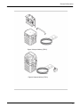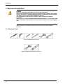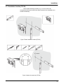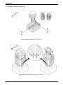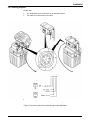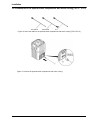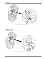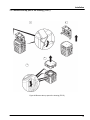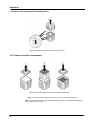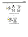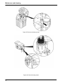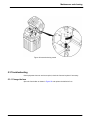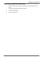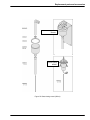
1
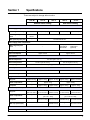
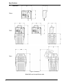
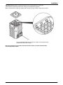
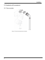
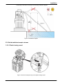
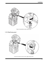
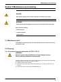
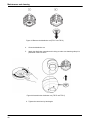
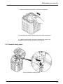
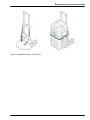
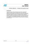
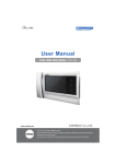
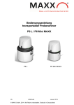
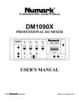
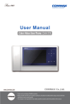
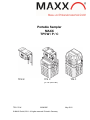
Portable Sampler
MAXX
TP5 W / P / C
TP5 W
TP5 P
TP5 C
(pic. with optional Box)
TP5 C-P-W
0250030E
© MAXX GmbH, 2011. All rights reserved. Printed in Germany
May 2012
Access code for programming and settings
Password:
Your Password:
6299
Table of Contents
Section 1 Specifications ......................................................................................................... 5
1.1 Dimensions ......................................................................................................................... 6
Section 2 General Information ................................................................................................ 7
2.1 Safety information ................................................................................................................ 7
2.1.1 Use of hazard information ................................................................................................. 7
2.1.2 Precautionary labels ......................................................................................................... 7
2.2 General Information ............................................................................................................. 8
2.2.1 Areas of application .......................................................................................................... 8
2.2.2 Functional description ...................................................................................................... 8
2.3 Product contents .................................................................................................................. 8
Section 3 Installation ............................................................................................................... 11
3.1 Mechanical installation ......................................................................................................... 12
3.1.1 Required tools ................................................................................................................... 12
3.1.2 Installation location (TP5 W) ............................................................................................ 13
3.1.3 Position (TP5 P and TP5 C ............................................................................................... 14
3.1.4 Attach the sampler compartment to the bottle compartment (TP5 P ................................. 15
3.2 Electrical connections .......................................................................................................... 15
3.2.1 Electrical installation ......................................................................................................... 16
3.2.1.1 Prepare the electrical installation ................................................................................... 16
3.2.1.2 Wiring diagram ............................................................................................................... 17
3.2.2 Installation of the optional bottle compartment with active cooling (TP5 P/TP5 C ............. 18
3.3 Commission of the equipment ............................................................................................. 20
3.3.1 Tube connection ............................................................................................................... 20
3.3.2 Set the individual sample volumes .................................................................................... 21
3.3.2.1 Plastic dosing vessel ...................................................................................................... 21
3.3.2.2 Glass dosing vessel ...................................................................................................... 23
3.3.2.3 Dosing vessel for flow-proportional sampling ................................................................ 25
3.3.3 Remove the top part of the housing (TP5 P) .................................................................... 27
3.3.4 Remove the top part of the housing (TP5 C) .................................................................... 28
3.3.5 Prepare the bottle compartments ...................................................................................... 28
3.3.6 Attach the top part of the housing...................................................................................... 29
3.3.7 Connect the equipment to the mains ................................................................................ 30
3.3.8 Switch on the device ........................................................................................................ 32
3.3.9 Adjust the cooling settings for the optional bottle compartment with active cooling (TP5 P
and
TP5 C ......................................................................................................................................... 33
Section 4 Operation ................................................................................................................. 35
4.1 Control unit operation .......................................................................................................... 35
4.1.1 Password ......................................................................................................................... 35
4.1.2 Programming .................................................................................................................... 35
4.1.3 Keyboard layout/function .................................................................................................. 35
4.2 Normal operation ................................................................................................................. 37
4.2.1 Replace the sample bottles ............................................................................................... 37
4
Section 5 Maintenance and cleaning ...................................................................................... 39
5.1 Maintenance tasks .............................................................................................................. 39
5.2 Cleaning .............................................................................................................................. 39
5.2.1 Clean the housing and distribution unit (TP5 P–TP5 C ..................................................... 39
5.2.2 Clean the dosing vessel ................................................................................................... 41
3
5.3 Troubleshooting ................................................................................................................... 43
5.3.1 Change the fuse ............................................................................................................... 43
5.4 Instrument decommissioning and storage ............................................................................ 45
Section 6 Replacement parts and accessories .................................................................... 47
6.1 Spare parts........................................................................................................................... 47
6.2 Accessories .......................................................................................................................... 50
Section 7 Warranty and Liability ............................................................................................. 53
4
Section 1
Specifications
These are subject to change without notice.
TP5 W
TP5 P
TP5 C
TP5 P
Without active cooling
TP5 C
With active cooling
Electrics
Power supply, sampler compartment
With integrated battery
With integrated power
pack
12 V-7,5 Ah (DC) 12 V-10 Ah (DC) 12 V-7,5 Ah (DC)
–
110–230 V/50–
–
60 Hz.
With optional power pack
12 V-10 Ah (DC)
–
110–230 V/50–60 Hz.
Power supply, bottle compartment
With integrated power
pack
12 V (DC)
110 V/60 Hz
230 V/50 Hz
–
Rating
or
(optional) or
(optional)
16 A
Power consumption
approx. 30 VA
approx. 50 VA
Environment
Medium temperature
0 to 40°C [32 to 104 °F]
Ambient temperature
0 to 50 °C [32 to 122 °F]
Delivery height
0 to 43 °C [32 to 110 °F]
< 6 m [20 ft], optional < 8 m [26 ft]
General specifications
Coolant
–
R134a
Maintenance requirements
Maintenance-free
Weight
Top part
approx. 6.6 kg
Bottle compartment
–
Complete
–
approx. 10 kg
approx. 14.3 kg
approx. 10 kg
approx. 11 kg
approx. 22 kg
approx. 25 kg
approx. 14.3 kg
approx. 25 kg
approx. 35 kg
approx. 40 kg
Dimensions (W X H X D)
Top part
475 x 362 x 222 445 x 442 x 222 510 x 390 x 468 445 x 442 x 222
[18.7x14.3x8.7] [17.5x17.4x8.7] [20x15.4x18.4] [17.5x17.4x8.7]
Bottle compartment
–
Complete
–
With cap opened (55°)
510 x 534 x 430
[20 x 21 x 16.9]
–
510 x 390 x 468
[20x15.4x18.4]
550 x 775 x 468
[21.7 x 30.5 x 18.4]
510 x 942 x 430 510 x 787 x 468 510 x 970 x 468
[20 x 37 x 16.9] [20 x 31 x 18.4] [20x38.2x18.4]
550 x 1028 x 468
[21.7x40.5x18.4]
510 x 970 x 468
[20x38.2x18.4]
510 x 1210 x 468
[20 x 47.6 x 18.4]
–
Certification
Certification
CE, sampling in accordance with ISO 5667-2/3-10
5
Specifications
1.1.
Dimension
TP5 W
TP5 P
TP5 C
Figure 1 Dimensions
W x H x D: see the specification table
6
Section 2 General Information
2.1 Safety information
Please read this entire manual before unpacking, setting up, or operating this equipment.
Pay attention to all danger and caution statements. Failure to do so may result in personal
injury or damage to the instrument.
To ensure that the protection provided by this equipment is not impaired, do not use or
install this equipment in any manner other than that specified in this manual.
2.1.1 Use of hazard information
DANGER
Indicates a potentially or imminently hazardous situation which, if not avoided, will
result in death or serious injury.
WARNING
Indicates a potentially or imminently hazardous situation that, if not avoided, could
result in death or serious injury.
CAUTION
Indicates a potentially or imminently hazardous situation that could result in
minor or moderate injury.
Important note: Information that requires special emphasis.
Note: Information that supplements points in the main text.
2.1.2 Precautionary labels
Read all labels and tags attached to the instrument. Failure to do so may result in
personal injury or damage to the instrument. A symbol, if noted on the instrument, will
be included with a danger or caution statement in the manual.
This symbol, if noted on the instrument, references the user manual for operation and/or
safety information.
This symbol, when noted on a product enclosure or barrier, indicates that a risk of
electrical shock and/or electrocution exists.
This symbol may appear on the product and indicates the need for protective eye wear.
This symbol may appear on the product and identifies the connection point for the
protective ground.
7
General Information
When this symbol appears on the product, it identifies the location of a fuse or a current
limiter.
Electrical equipment marked with this symbol may not be disposed of in European domestic or public disposal
systems after 12 August 2005. In conformity with European local and national regulations (EU Directive
2002/96/EC), European electrical equipment users must now return old or end-of-life equipment to the
manufacturer for disposal at no charge to the user
Note: For return for recycling, please contact the equipment manufacturer or supplier for instructions on how
to return end-of-life equipment, manufacturer-supplied electrical accessories, and all auxiliary items for proper
disposal.
2.2 General Information
2.2.1 Areas of application
The equipment is used for sampling aqueous liquids with a temperature of 0 °C to 50 °C
(refer to Section 1 Specifications, page 5).
2.2.2 Functional description
The equipment provides temporary storage for liquids of a specified volume so that they
can be analyzed.
2.3 Product contents
The equipment is supplied with a tube and brief operating instructions.
Depending on the model, the equipment is also supplied with a plug (TP5 W/active cooled
bottle compartment), tension belt (TP5 P) or an optional charger (TP5 P/TP5 C).
If you require further information, you can order the operating instructions (refer to
Section 6 Replacement parts and accessories, page 47) from the manufacturer or you can
download them from the Internet.
INPUT- plug
1,7 m
Figure 2 Scope of delivery (TP5 W)
8
General Information
Figure 3 Scope of delivery (TP5 P)
Figure 4 Scope of delivery (TP5 C)
9
General Information
10
Installation
Section 3 Installation
DANGER
Only qualified experts should conduct the tasks described in this section.
DANGER
Select an appropriate installation location for the instrument.
Plan out the mechanical mount·before positioning poles or drilling holes. Make
sure the mount has a sufficient bearing capacity. The dowels must be selected and
authorized according to the condition of the wall.
The manufacturer shall accept no liability if the instrument is installed incorrectly.
Plan how to lay cables and tubes and their path in advance. Lay the tubes, data
cables and power cables without any bends and so they do not pose a tripping
risk.
Do not connect the electrical supply to the mains if the equipment has not been
wired and fused correctly.
Sufficiently protect the electrical power supply against short circuits.
For the external power supply, always connect a residual-current circuit
breaker·(trip current max.: 30 mA) between the mains and the system.
If the equipment is to be installed outdoors, switch the overload protection
between mains and system.
Products intended by the manufacturer for outdoor use offer a higher level of
protection against the penetration of liquids and dust. If these products are
connected to a mains outlet with a cable and plug·rather than a permanently
connected cable, the plug and outlet are much more susceptible to liquid and dust
penetration. The operator must sufficiently protect the plug and outlet against
liquid and dust penetration in accordance with local safety regulations. If the
instrument is to be used outdoors, it must be connected to a suitable outlet with a
protection type of at least IP44 (splash protection).
11
Installation
3.1 Mechanical Installation
DANGER
Select an appropriate installation location for the instrument.
Plan out the mechanical mount·before positioning poles or drilling holes. Make
sure the mount has a sufficient bearing capacity. The dowels must be selected
and authorized according to the condition of the wall.
The manufacturer shall accept no liability if the instrument is installed
incorrectly.
Plan how to lay cables and tubes and their path in advance. Lay the tubes, data
cables and power cables without any bends and so they do not pose a tripping
risk.
Note : For information on installation with optional accessories, refer to the relevant installation
instructions.
3.1.1 Required Tools
Figure 5 Required tools (TP5 W)
Figure 6 Required tools (TP5 P und TP5 C)
12
Installation
3.1.2 Installation location (TP5 W)
Select suitable fastening materials (e.g. 6 x 40 mm screws and
corresponding dowels) and read all the safety information about installation and
mechanical assembly.
Figure 7 Select installation location (TP5 W)
210 mm
210 mm
Figure 8 Attach the equipment (TP5 W)
13
Installation
3.1.3 Position (TP5 P und TP5 C)
Figure 9 Select the position (TP5 P und TP5 C)
Figure 10 Position the equipment (TP5 P und TP5 C)
14
Installation
3.1.4 Attach the sampler compartment to the bottle compartment (TP5 P)
Figure 11 Attach the sampler compartment to the bottle compartment (TP5 P)
3.2 Electrical Connections
DANGER
Only qualified experts should conduct the tasks described in this section.
DANGER
Do not connect the electrical supply to the mains if the equipment has not been
wired and fused correctly.
Sufficiently protect the electrical power supply against short circuits.
For the external power supply, always connect a residual-current circuit
breaker·(trip current max.: 30 mA) between the mains and the system.
If the equipment is to be installed outdoors, switch the overload protection
between mains and system.
If the mains plug·of the power supply cable·is removed, a suitable double-pole
one-way switch must be installed immediately next to the display unit·with clear
labeling for the power supply.
Products intended by the manufacturer for outdoor use offer a higher level of
protection against the penetration of liquids and dust. If these products are
connected to a mains socket with a cable and plug·rather than a permanently
15
Installation
connected cable, the plug and socket are much more susceptible to liquid and
dust penetration. The operator must sufficiently protect the plug and outlet against
liquid and dust penetration in accordance with local safety regulations. If the
instrument is to be used outdoors, it must be connected to a suitable outlet with a
protection type of at least IP44 (splash protection)
3.2.1 Electrical installation
3.2.1.1 Prepare the electrical installation
In battery mode
In mains power mode
TP5 W
–
Keine Vorbereitung notwendig
TP5 P
No preparation required
Connect the optional charger to the charge socket on the left-hand
side.
TP5 C
No preparation required
Connect the Y cable as shown in Figure 12.
Figure 12 Connect the Y cable (TP5 C)
To connect the equipment to the mains, see Figure 36 Model TP5 C with Y
cable and charger on page 31.
16
Installation
3.2.1.2 Wiring diagram
Please note:
·
·
The assignment of the connections in the illustration below
The cable color of the label on the cable.
·
Figure 13 Connection plan for the optional signal cable (0069644)
17
Installation
3.2.2 Installation of the optional bottle compartment with active cooling (TP5 P / TP5 C)
115 V/60 Hz
230 V/50 Hz
12 V
Figure 14 Select the cable for the optional bottle compartment with active cooling (TP5 P/TP5 C)
Figure 15 Connect the optional bottle compartment with active cooling
18
Installation
Important note: Blocked air outlets and liquids in the cooling machine or inside the
optional bottle compartment with active cooling can damage the equipment.
Make sure that the air outlets are always open and that no liquid is able to enter the air outlets..
Figure 16 Sample distributor plate and air outlets on the optional bottle
compartment with active cooling
Note: The housing base on the bottle compartment features numbers so that the individual bottles
can be assigned with a number
19
Installation
3.3 Commission of the equipment
3.3.1 Tube connection
Figure 17 Connect the sample tube connection
20
Installation
Positioning of the tubes according to the following installation diagram.
1
0–40 °C
[32–104 °F]
> 50 µs
Figure 18 Installation diagram
3.3.2 Set the individual sample volumes
3.3.2.1 Plastic dosing vessel
1
Figure 19 Unlock the bayonet cap on the plastic dosing vessel
21
Installation
Figure 20 Remove the plastic dosing vessel
V-Probe [ml]
Figure 21 Cut the dosing tube to set the sample volume
22
Installation
Figure 22 Assemble the plastic dosing vessel
3.3.2.2 Glas-Dosing vessel
,
Figure 23 Loosen the union nut on the glass dosing vessel
23
Installation
Figure 24 Remove the glass dosing vessel
Figure 25 Cut the dosing tube to set the sample volume
24
Installation
Figure 26 Assemble the glass dosing vessel
3.3.2.3 Dosing vessel for flow-proportional sampling
Figure 27 Calibrate the flow-proportional dosing vessel via the service menu
25
Installation
∆P = =[hPa, bar]
Figure 28
26
The flow-proportional dosing vessel can only be used,
if there is NO counter pressure
Installation
3.3.3 Remove the top part of the housing (TP5 P)
1
2
1
4
3
Figure 29 Remove the top part of the housing (TP5 P)
27
Installation
3.3.4
Remove the top part of the housing (TP5 C)
Figure 30 Remove the top part of the housing (TP5 C)
3.3.5 Prepare the bottle compartments
Figure 31 Place the empty bottles into the bottle compartment
Note: The sample distributor plate works correctly in all four of its potential positions. .
Note: The housing base of the bottle compartment features numbers so that the individual bottles
can be assigned with a number..
28
Installation
3.3.6 Attach the top part of the housing
Figure 32 Attach the top part of the housing (TP5 P)
Figure 33 Attach the top part of the housing (TP5 C)
29
Installation
3.3.7 Connect the equipment to the mains
Make sure that:
• The equipment has been fully prepared for commissioning
• The data on the type plate corresponds to the data relating to the mains power supply
(this applies to TP5 W as well as to TP5 P and TP5 C in connection with the charger and Y
plug BM69742
• The correct plug has been attached or the direct wire has been implemented correctly
• The equipment can be put into operation without any risks
DANGER
Make sure that the power supply, cable (also refer to Figure 14, page 18) and
equipment are suitable for use with each other..
Figure 34 Rating label
30
Installation
Figure 35 Possible connection configurations (TP5 W)
Figure 36 Model TP5 C with Y cable and charger
31
Installation
Figure 37 Potential connection variations (optional bottle compartment with active cooling)
3.3.8 Switch on the device
I/O
I/O
I/O
Figure 38 Switch on the device
32
Installation
3.3.9 Adjust the cooling settings for the optional bottle compartment with active cooling
(TP5 P / TP5 C)
The manufacturer recommends a settings range of +4 to +15 °C.
Figure 39 Adjust the cooling settings for the optional bottle compartment with active cooling
33
Installation
34
Operation
4.1 Control unit operation
All the equipment functions are software-controlled
software
4.1.1 Password
Password to program sampler and to change settings is:
is
6299
4.1.2 Programming
The menu structure resembles the directory structure of a computer hard drive and is
divided into main menus and sub menus
4.1.3 Keyboard layout/function
The equipment can be programmed by the operator
Figure 40 Control panel
The key functions are configured as follows to enable highly intuitive operation
operation:
Tabelle 1 1 Key functions
Display help text
(in the case of selection fields,
hand side)
the cursor must be placed on the left-hand
Arrow key
Move from one menu item to the next menu selection
Arrow key
Select the desired menu
Enter-Taste
Move within a menu
Arrow key
Select from within a menu
Arrow key
35
Operation
Tabelle 1 Tastenfunktion (Fortsetzung)
Confirm the selection
(automatically marked with a ü)
Enter-key
Enter/change values
Arrow key
Confirm the entered values
Enter- key
Return to the next superordinate menu level
Back- key
Enter values
Numeric keypad
Initialise (Reset) of Display - Press together
Back-key + Enter
+
Wakeup sleepmode (press 5 sec. at least)
Restore factory settings (Display = „load
load factorysettings“)
factorysettings
Hold Back-key until boot process is finished
Back- key
Back- key
Example: A setting needs to be changed.
1. Press Enter.
The cursor then flashes.
2. Use the arrow keys to move the cursor until it is in the required position.
3. Press Enter.
The selection is now confirmed and the program can be started
started.
36
Operation
Figure 41 Start the program
Depending on the program range,
• an activity is started or
• the next menu item is automatically selected.
Note: The general rule:
If you press Back,
– the activity is cancelled or
– the navigation takes one step back in the men
4.2 Normal operation
4.2.1 Replace the sample bottles
1
2
3
4
Figure 42 Replace full bottles
37
Operation
38
Maintenance and cleaning
Section 5 Maintenance and cleaning
DANGER
Only qualified experts should conduct the tasks described in this section.
WARNING
Please observe the following points for the use of chemicals and/or waste water:
Wear protective clothing:
– Laboratory coat
– Protective eyewear
– Rubber gloves
5.1 Maintenance work
The sampler is maintenance-free. Thus the operator does not need to carry out any
maintenance work.
5.2 Cleaning
5.2.1 Clean the housing and distribution unit (TP5 P–TP5 C)
WARNING!
Manual rotation of the distribution unit can damage the drive.
Never rotate the distribution unit manually.
Clean the interior and exterior of the housing with a damp, lint-free cloth. Add commercial
household cleaner to the cleaning water as required.
1. Clean the exterior of the housing.
2. Remove the top part as shown in the illustrationsFigure 29, Page 27 and Figure 30,
Page 28.
3. Loosen the central nut and remove the distribution vat.
39
Maintenance and cleaning
1
2
Figure 43 Remove the distribution vat (TP5 P und TP5 C)
4.
Clean the distribution vat
5.
Attach the distribution vat again and in doing so make sure that the guide pin is
positioned in the bore hole.
Figure 44 Assemble the distribution vat (TP5 P und TP5 C)
6. Tighten the central nut by hand again
40
Maintenance and cleaning
7. Clean the sample distributor plate on the bottle compartment
Figure 45 Clean the sample distributor plate on the bottle compartment
8. Position the top part back on the bottle compartment as shown in the
illustrations. Figure 32, Page 29 and Figure 33, Page 29
5.2.2 Clean the dosing vessel
Figure 46 Release the dosing vessel
41
Maintenance and cleaning
Figure 47 Remove the dosing vessel
Figure 48 Clean the dosing vessel
42
Maintenance and cleaning
Figure 49 Insert the dosing vessel
5.3 Troubleshooting
If the equipment does not work as required, check the fuse and replace if necessary
5.3.1 Change the fuse
Open the fuse holder as shown in Figure 50 and replace the defective fuse.
43
Maintenance and cleaning
Figure 50 Position of the fuse in the portable sampler
Figure 51 Position of the fuse in the optional bottle compartment with active cooling
If the error is not rectified, please contact the customer service of the
manufacturer (refer to Contact information, page 55)
44
Maintenance and cleaning
5.4 Instrument decommissioning and storage
1.
Remove all liquids and, if necessary, solid matter from the infeed and outfeed
lines
and bottle compartments and clean as required.
2.
Close all active programs.
3.
Switch the equipment off.
45
Maintenance and cleaning
46
Replacement parts and accessories
Section 6 Replacement parts and accessories
6.1 Spare parts
Description
Replacement bottle, glass, 1 L
Cap for 1 L glass bottle
Replacement bottle, glass, 20 L
Replacement bottle, PE, 1 L
Cap for 1 L PE bottle
Replacement bottle, PE, 25 L (with cap)
Replacement bottle, PE, 5 L (with cap)
Replacement bottle, PE, 13 L (with cap)
Replacement battery TP5 P
Replacement battery TP5 C
Art.No.
0030030
0060533
0030045
0060486
0060488
0060046
0060038
0060045
0010012
0900116
47
Replacement parts and accessories
Plastic dosing vessel
900715
Valve system
900627
Figure 52 Plastic dosing vessel
48
Replacement parts and accessories
Glas dosing vessel
900743
Valve system
900627
Figure 53 Glass dosing vessel (350 ml)
49
Replacement parts and accessories
6.2 Accessories
Description
Y cable, power supply
Charger IP20 for TP5 P und TP5 C
Charger IP65 for TP5 P und TP5 C
Signal cabel 10 m
RS232 serial data cabel
PC Software Read Data
Tube connection with screw connection
Battery for bottle compartment with active cooling (90 Ah)
Sample transportation box (without bottles)
Replacement cooling battery
Transportation trolley
Figure 54 Charger IP20
Figure 55 Charger IP65
50
Art.No.
0069742
0900026
0900033
0069644
0900021
0200004
0900300
0010211
0900634
0060251
0900802
Replacement parts and accessories
Figure 56 Transportation trolley (TP5 P/TP5 C)
51
Replacement parts and accessories
52
Warranty and liability
Chapter 7
Warranty and liability
The manufacturer warrants that the product supplied is free of material
and manufacturing defects and undertakes the obligation to repair or
replace any defective parts at zero cost.
The warranty period is 12 months from delivery resp. invoice date.
Consumables and damage caused by improper handling, poor
installation or incorrect use are excluded from this clause
With the exclusion of the further claims, the supplier is liable for defects
including the lack of assured properties as follows: all those parts that,
within the warranty period calculated from the day of the transfer of risk,
can be demonstrated to have become unusable or that can only be used
with significant limitations due to a situation present prior to the transfer of
risk, in particular due to incorrect design, poor materials or inadequate
finish will be improved or replaced, at the supplier's discretion. The
identification of such defects must be notified to the supplier in writing
without delay, however at the latest 7 days after the identification of the
fault. If the customer fails to notify the supplier, the product is considered
approved despite the defect. Further liability for any direct or indirect
damages is not accepted.
If instrument-specific maintenance and servicing work defined by the
supplier is to be performed within the warranty period by the customer
(maintenance) or by the supplier (servicing) and these requirements are
not met, claims for damages due to the failure to comply with the
requirements are rendered void.
Any further claims, in particular claims for consequential damages cannot
be made.
Consumables and damage caused by improper handling, poor
installation or incorrect use are excluded from this clause.
53
MAXX Mess- u. Probenahmetechnik GmbH
Hechinger Str. 41, D-72414 Rangendingen
Tel. +49(0)7471-98481 0 Fax +49(0)7471-98481 44
www.maxx-gmbh.com
[email protected]