1
F1220A
EUROLIVE
User Manual
A50-56333-00001
EUROLIVE F1220A
Important safety instructions
**
This symbol, wherever it appears, alerts you to the
presence of uninsulated dangerous voltage inside the
enclosure - voltage that may be sufficient to constitute
a risk of shock.
!!
This symbol, wherever it appears, alerts you to important
operating and maintenance instructions in the accompanying literature. Please read the manual.
Caution
9) Do not defeat the safety purpose of the polarized or
grounding-type plug. A polarized plug has two blades with
one wider than the other. A grounding-type plug has two
blades and a third grounding prong. The wide blade or the
third prong are provided for your safety. If the provided
plug does not fit into your outlet, consult an electrician
for replacement of the obsolete outlet.
10)Place the power cord so that it is protected from being
walked on and sharp edges. Be sure that the power cord is
protected particularly at plugs, convenience receptacles
and the point where it exits from the apparatus.
11) Use only attachments/accessories specified by the
manufacturer.
12)Use only with the cart, stand, tripod, bracket, or table
specified by the manufacturer, or sold with the apparatus.
When a cart is used, use caution when moving the cart/
apparatus combination to avoid injury from tip-over.
++ To reduce the risk of electric shock, do not remove the
top cover (or the rear section). No user serviceable parts
inside. Refer servicing to qualified personnel.
Warning
++ To reduce the risk of fire or electric shock, do not expose
this appliance to rain and moisture. The apparatus shall
not be exposed to dripping or splashing liquids and no
objects filled with liquids, such as vases, shall be placed
on the apparatus.
13)Unplug this apparatus during lightning storms or when
unused for long periods of time.
Caution
14)Refer all servicing to qualified service personnel.
Servicing is required when the apparatus has been damaged in any way, such as power supply cord or plug is
damaged, liquid has been spilled or objects have fallen
into the apparatus, the apparatus has been exposed to
rain or moisture, does not operate normally, or has been
dropped.
++ These service instructions are for use by qualified service personnel only. To reduce the risk of electric shock
do not perform any servicing other than that contained in
the operation instructions. Repairs have to be performed
by qualified service personnel.
16)Where the MAINS plug or an appliance coupler is used as
the disconnect device, the disconnect device shall remain
readily operable.
15)The apparatus shall be connected to a MAINS socket
outlet with a protective earthing connection.
1) Read these instructions.
2) Keep these instructions.
3) Heed all warnings.
4) Follow all instructions.
5) Do not use this apparatus near water.
6) Clean only with dry cloth.
7) Do not block any ventilation openings. Install in accordance with the manufacturer’s instructions.
8) Do not install near any heat sources such as radiators,
heat registers, stoves, or other apparatus (including
amplifiers) that produce heat.
2
EUROLIVE
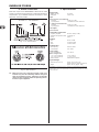
EUROLIVE F1220A
== High-performance, 125-Watt, active monitor system for live and playback applications
== Exceptional sound quality, wide frequency bandwidth and dynamic range
F1220A
High-Performance, Active 125-Watt Monitor Speaker System with
12" Woofer, 1" Compression Driver and Feedback Filter
== Adjustable feedback filter and integrated limiter for ultimate system control and speaker protection
== Ultra-low noise Mic/Line input with Volume control and peak LED
== Dedicated 3-band EQ for perfect sound shaping
== Powerful 12'' long-excursion driver provides incredibly deep bass and acoustic power
== High-resolution 1'' HF driver for exceptional high-frequency reproduction
== Proprietary horn design for ultra-wide sound dispersion
== Integrated 35 mm pole socket for stand mounting and use as PA system
== High-quality components and exceptionally rugged construction ensure long life
== Conceived and designed by BEHRINGER Germany
3
EUROLIVE F1220A
Foreword
Dear Customer,
Welcome to the team of
BEHRINGER users, and
thank you very much for
expressing your confidence in us by purchasing
this floor monitor system.
Writing this foreword for
you gives me great pleasure, because it represents the culmination of
many months of hard work
delivered by our engineering team to achieve a very
ambitious goal: a firstgrade monitor speaker
which stands out for its
excellent sound quality
on stage. The task of designing our new F1220A
certainly meant a great
deal of responsibility, which we assumed by focusing on you, the
discerning user and musician. Meeting your expectations also
meant a lot of work and night shifts. But it was fun, too. Developing
a product usually brings a lot of people together, and what a great
feeling it is when all who participated in such a project can be
proud of what they’ve achieved.
Table of contents
1. Introduction.......................................................................... 5
1.1 Before you get started................................................... 5
1.1.1 Shipment.............................................................. 5
1.1.2 Initial operation.................................................... 5
1.1.3 Online Registration.............................................. 5
2. Control elements and connections.................................... 6
2.1 Top panel....................................................................... 6
2.2 Side panel..................................................................... 6
3. Operation............................................................................. 7
3.1 Connecting signal sources............................................ 7
3.2 Connecting multiple F1220A speakers......................... 7
3.3 Using F1220A as keyboard amplifier............................ 7
3.4 Notch filter..................................................................... 7
4. Audio connectors................................................................ 8
5. Specifications...................................................................... 8
6. Warranty............................................................................... 9
It is our philosophy to share our enjoyment with you, because you
are the most important member of the BEHRINGER team. With
your highly competent suggestions for new products you’ve made
a significant contribution to shaping our company and making it
successful. In return, we guarantee you uncompromising quality
as well as excellent technical and audio properties at an extremely
reasonable price. All of this will enable you to give free rein to your
creativity without being hampered by budget constraints.
We are often asked how we manage to produce such high-quality
devices at such unbelievably low prices. The answer is quite
simple: it’s you, our customers! Many satisfied customers mean
large sales volumes enabling us to get better purchasing terms
for components, etc. Isn’t it only fair to pass this benefit on to you?
Because we know that your success is our success too!
I would like to thank all of you who have made the F1220A possible. You have all made your own personal contributions, from
the developers to the many other employees at this company, and
to you, the BEHRINGER user.
My friends, it’s been worth the effort!
Thank you very much,
Uli Behringer
4
EUROLIVE F1220A
1. Introduction
1.1.3 Online Registration
Thank you very much for expressing your confidence in
BEHRINGER products by purchasing the EUROLIVE F1220A floor
monitor system. With its comprehensive features and first-grade
speakers, the active EUROLIVE F1220A floor monitor system
provides the perfect solution for live and playback applications
on small- and middle-sized stages. The input section allows you
to connect either to a Line source or microphone. There is an
adjustable feedback filter and an integrated limiter for ultimate
system control and speaker protection plus a dedicated 3-band
EQ for perfect sound shaping.
1.1 Before you get started
1.1.1 Shipment
Your product was carefully packed at the factory to ensure safe
transport. Nevertheless, if the box is damaged inspect the unit
immediately for signs of damage.
Please register your new BEHRINGER equipment right after your
purchase by visiting http://www.behringer.com and read the terms
and conditions of our warranty carefully.
Should your BEHRINGER product malfunction, it is our intention
to have it repaired as quickly as possible. To arrange for warranty
service, please contact the BEHRINGER retailer from whom the
equipment was purchased. Should your BEHRINGER dealer not
be located in your vicinity, you may directly contact one of our
subsidiaries. Corresponding contact information is included in
the original equipment packaging (Global Contact Information/
European Contact Information). Should your country not be
listed, please contact the distributor nearest you. A list of distributors can be found in the support area of our website (http://www.
behringer.com).
Registering your purchase and equipment with us helps us process
your repair claims more quickly and efficiently.
Thank you for your cooperation!
++ If the unit is damaged please do NOT return it to us,
but notify your dealer and the shipping company immediately; otherwise, claims for damage or replacement
may not be granted.
++ Always use the original box to prevent damage during
storage or transport.
++ Make sure that children cannot play unsupervised with
the unit or its packaging.
++ Please ensure proper disposal of all packing
materials.
1.1.2 Initial operation
Ensure adequate air supply and to avoid overheating do not place
the unit near radiators etc.
Caution
++ Before you change the fuse, switch off the device and
pull the plug to avoid electric shock or damage to the
device.
++ Blown fuses must be replaced by fuses of the correct
rating! Please refer to the “Specifications” section for
the applicable rating.
The fuse holder on the mains connector has 3 triangular markings.
Two of these triangles opposing each other. The device is set to
the operating voltage printed next to these markers and can be
set to another voltage by turning the fuse holder by 180°.
For connection to the mains use the enclosed power cord with cold
connector which complies with the relevant safety regulations.
++ Please make sure that all devices are properly grounded.
For your own safety, never remove or disable the ground
conductors from the devices or on the power cords. The
unit must always be connected to the mains outlet with
a protective grounding connection.
Caution
++ This loudspeaker is capable of producing extreme volumes. Please keep in mind that high sound pressures do
not only temporarily damage your sense of hearing, but
can also cause permanent hearing damage. Be careful
to select a suitable volume at all times.
Important notes concerning installation
++ The sound quality may diminish within the range of powerful broadcasting stations and high-frequency sources.
Increase the distance between the transmitter and the
device and use shielded cables for all connections.
Introduction
5
EUROLIVE F1220A
2. Control elements and connections
2.1 Top panel
Fig. 2.4: LINK OUTPUT
Fig. 2.1: First group control
{1} The POWER LED lights up when the loudspeaker is put into
operation.
{7} + {8}
The LINK OUTPUT is directly connected to the inputs of
the F1220A and carries the input signal with no processing
applied. In this way, you can route the signal to the input of
another device (for example, a second F1220A).
{2} The CLIP LED lights up when signal distortion occurs.
Reduce the volume with the LEVEL control until the CLIP
LED does not light up any more, or occasionally lights up at
signal peaks.
{3} To set the volume of the LINE or MIC signal, use the LEVEL
control. The left half of the control range is for attenuating
the LINE signal. The right half is for raising the level of the
MIC signal.
Level adjusting: Turn the LEVEL control whose signal you
want to adjust slowly to the right until the CLIP LED {2}
lights up only at signal peaks. The LED is not supposed to
glow continuously.
++ We would like to draw your attention to the fact that extremely loud sound levels may damage your hearing as
well as your headphones/loudspeakers. Turn the LEVEL
control fully to the left before you switch on the unit. Be
careful to select a suitable volume at all times.
Fig. 2.5: MIC/LINE INPUT
{9} Use this 1/4" stereo jack to connect a signal source that has
1/4" output.
(10) Use this XLR connector to connect a signal source that has
XLR output.
++ Always use either the XLR or the 1/4" jack input, and use
the LEVEL control to adapt the input sensitivity. Never
use both inputs at the same time!
2.2 Side panel
Fig. 2.2: Equalizer
{4} The F1220A features a 3-band sound control. Each band
provides a maximum boost/cut of 15 dB. At center position
the equalizer has a flat response.
The upper (EQ HIGH) and the lower band (EQ LOW) are
shelving filters that boost and cut all frequencies above and
below the crossover frequency. The crossover frequencies
of the upper and lower bands are at 12 kHz and 80 Hz, respectively. The mid band (EQ MID) is a peak filter the center
frequency of which is at 2.5 kHz.
Fig. 2.6: Side panel F1220A
(11) Press POWER to turn on your F1220A.
++ The POWER switch does not fully disconnect the unit
from the mains. To disconnect the unit from the mains,
pull out the main cable plug or appliance coupler. When
installing the product, ensure the plug or appliance
coupler is readily operable. Unplug the power cord
completely when the unit is not used for prolonged
periods of time.
(12) You can replace fuses at the FUSE SWITCH of the F1220A.
Always replace fuses with the same type. Please follow the
instructions given in the chapter “Specifications.”
Fig. 2.3: Feedback filter (notch filter)
Feedback may occur at high volume levels or under difficult stage
situations. Use the FEEDBACK FILTER function ({5}, {6}) to
reduce feedback. To learn more about the feedback filter, read
section 3.4 “Notch filter.”
(13) The mains connection is established using a cable with
an IEC mains connector. This cable is delivered with the
F1220A. To avoid ground-loop hum, loudspeakers and
mixing consoles should be connected to the same power
circuit.
(14) Serial number
{5} This switch turns on the feedback filter.
{6} This control adjusts the center frequency of the feedback
filter.
6
Control elements and connections
EUROLIVE F1220A
3. Operation
3.2 Connecting multiple F1220A speakers
Use the Monitor/Aux output of a mixer to route the audio signal to
the F1220A. When using the monitor mix with more loudspeakers,
route the audio signal of the first F1220A to the next speaker via
the LINK output. The volume level of each F1220A is adjusted
with the respective LEVEL control.
If you want to use the same monitor mix on bigger stages, simply
increase the number of stage monitors. For example, connect two
F1220A monitors via the LINK output. Either a microphone or line
signal can be routed to the first F1220A.
Connecting to an active loudspeaker
== Connect the LINK output of the first loudspeaker with the LINE
input of the second loudspeaker.
3.1 Connecting signal sources
With an F1220A and a microphone, you are able to master small
PA tasks with minimum effort. The F1220A can also be used
with equipment which include LINE outputs, such as keyboards,
playback devices (for example, CD players) and mixers with AUX
Send outputs.
Connecting a signal source
== Turn the LEVEL control fully to the left.
== Connect the signal source to the MIC/LINE input.
== Turn on the F1220A.
== Turn the LEVEL control slowly to the right until you have
reached the desired volume level. The CLIP LED helps you
in this case. The LED should only light up at signal peaks, but
shouldn’t glow continuously.
3.3 Using F1220A as keyboard amplifier
Usually guitar and bass guitar players have amplifiers which allow
them to be heard when playing on stage—even when a monitor
system is being used. These amps have enough power to be
used on smaller stages. However, it’s quite a different matter for
the keyboardists because they normally won’t use instrument
amplifiers.
It is possible to connect a keyboard directly to the F1220A. In case
you want to hook up two keyboards, use a submixer, such as the
MicroMIX MX400, to join both signals and then connect the mixer’s
output to the LINE input of the F1220A. Route the Aux/Monitor
signal coming from the main mixer to the submixer so that you
can hear your band members as well (see fig. 3.1).
Caution: risk of feedback!
++ Don’t let the microphone’s most sensitive side (front)
face the loudspeaker. Make sure to keep sufficient
distance between the microphone and the loudspeaker
when using the F1220A.
Fig. 3.1: F1220A with two keyboards
3.4 Notch filter
A notch filter cancels a narrow frequency band of the signal being
used. Typical interferences, such as feedback and rumble, are
found close to the signal and are therefore easily filtered out.
To pinpoint the interfering frequency, activate the filter and slowly
turn the FREQUENCY control from the left to the right.
++ We recommend using our proven FEEDBACK
DESTROYER PRO FBQ2496 feedback suppressor for
signals with line level should continuous feedback
problems occur. For line- or microphone-level signals,
we recommend our SHARK DSP110 signal processor.
Operation
7
EUROLIVE F1220A
4. Audio connectors
5. Specifications
Both audio inputs of the BEHRINGER F1220A and the LINK
OUTPUT connector are fully balanced. To maximize interference
compensation, try to establish balanced connections to other
equipment, whenever possible.
Output power
RMS @ 1% THD
Peak power
90 W / 8 Ω
125 W / 8 Ω
Input
XLR connector (servo-balanced)
Sensitivity
Input impedance
¼" TRS jack (servo-balanced)
Sensitivity
Input impedance
-50 dBu to +10 dBu
11 kΩ balanced; 30 kΩ unbalanced
-50 dBu to +10 dBu
11 kΩ balanced; 30 kΩ unbalanced
Link output
XLR connector
Loudspeaker system data
Frequency response
60 Hz to 18 kHz (-10 dB)
Maximum sound pressure level 121 dB @ 1 m
Limiter
optical
Equalizer
LOW
MID
HIGH
Fig. 4.1: ¼" TRS connector
Feedback filter
Filter frequency
Level reduction
Power supply
Power consumption
Mains voltage / Fuse
100 - 120 V~ (50/60 Hz)
220 - 230 V~ (50/60 Hz)
Mains connector
Physical/weight
Dimensions (H x W x D)
Weight
300 Hz to 6 kHz
max. 15 dB
max. 180 W
T 2.5 A H 250 V
T 1.25 A H 250 V
standard IEC receptacle
approx. 14.2" x 22.8" x 16"
(approx. 360 mm x 580 mm x 406 mm)
approx. 39.7 lb. (approx. 18 kg)
BEHRINGER is constantly striving to maintain the highest professional standards.
As a result of these efforts, modifications may be made from time to time to existing
products without prior notice. Specifications and appearance may differ from those
listed or illustrated.
Fig. 4.2: XLR connectors
++ Make sure that only competent people install your
F1220A. They must be sufficiently earthed during and
after the installation process. Otherwise, electrostatic
discharges may negatively affect the operating characteristics of your equipment.
8
80 Hz / ±15 dB
2.5 kHz / ±15 dB
12 kHz / ±15 dB
Specifications
EUROLIVE F1220A
6. Warranty
§ 1 Other warranty rights and national law
1. This warranty does not exclude or limit the buyer’s statutory rights provided by national law, in particular, any such rights against the seller that
arise from a legally effective purchase contract.
2. The warranty regulations mentioned herein are applicable unless they
constitute an infringement of national warranty law.
§ 2 Online registration
Please do remember to register your new BEHRINGER equipment right
after your purchase by visiting http://www.behringer.com and kindly read the
terms and conditions of our warranty carefully. Registering your purchase
and equipment with us helps us process your repair claims quicker and
more efficiently.
Thank you for your cooperation!
§ 3 Warranty
1. BEHRINGER (BEHRINGER International GmbH including all
BEHRINGER subsidiaries, except BEHRINGER Japan) warrants the mechanical and electronic components of this product to be free of defects in
material and workmanship for a period of one (1) year* from the original
date of purchase, in accordance with the warranty regulations described
below. If the product shows any defects within the specified warranty
period that are not excluded from this warranty as described under § 5,
BEHRINGER shall, at its discretion, either replace the product by providing
a new or reconditioned product or repair the product using suitable new or
reconditioned parts. In the case that other parts are used which constitute an
improvement, BEHRINGER may, at its discretion, charge the customer for
the additional cost of these parts. In case BEHRINGER decides to replace
the product, this warranty shall apply to the replacement product for the
remaining initial warranty period, i.e one year* from the date of purchase
of the initial product.
2. If the warranty claim proves to be justified, the product will be returned
to the user freight prepaid.
3. Warranty claims other than those indicated above are expressly
excluded.
§ 4 Return authorization number
1. To obtain warranty service, the buyer (or his authorized dealer) must call
BEHRINGER during normal business hours BEFORE returning the product.
All inquiries must be accompanied by a description of the problem. The buyer
or his authorized dealer will receive a return authorization number.
2. Subsequently, the product must be returned in its original shipping carton,
together with the return authorization number. The return shipment address
will be indicated by BEHRINGER.
3. Shipments without freight prepaid will not be accepted.
2. If the product needs to be modified or adapted in order to comply with
applicable technical or safety standards on a national or local level, in any
country which is not the country for which the product was originally developed and manufactured, this modification/adaptation shall not be considered
a defect in materials or workmanship. The warranty does not cover any such
modification/adaptation, irrespective of whether it was carried out properly
or not. Under the terms of this warranty, BEHRINGER shall not be held
responsible for any cost resulting from such a modification/adaptation.
3. Free inspections and maintenance/repair work are expressly excluded
from this warranty, in particular, if caused by improper handling of the product
by the user. This also applies to defects caused by normal wear and tear,
in particular, of faders, crossfaders, potentiometers, keys/buttons, tubes,
guitar strings, illuminants and similar parts.
4. Damage/defects caused by the following conditions are not covered by
this warranty:
== improper handling, neglect or failure to operate the unit in compliance with the instructions given in BEHRINGER user or service
manuals.
== connection or operation of the unit in any way that does not comply
with the technical or safety regulations applicable in the country
where the product is used.
== damage/defects caused by force majeure or any other condition
that is beyond the control of BEHRINGER.
5. Any repair or opening of the unit carried out by unauthorized personnel
(user included) will void the warranty.
6. If an inspection of the product by BEHRINGER shows that the defect in
question is not covered by the warranty, the inspection costs are payable
by the customer.
7. Products which do not meet the terms of this warranty will be repaired
exclusively at the buyer’s expense. BEHRINGER will inform the buyer of any
such circumstance. If the buyer fails to submit a written repair order within
6 weeks after notification, BEHRINGER will return the unit. Costs for freight
and packing will be invoiced separately C.O.D. When the buyer has sent in
a written repair order such costs will also be invoiced separately.
§ 6 Warranty transferability
This warranty is extended exclusively to the original buyer (customer of retail
dealer) and is not transferable to anyone who may subsequently purchase
this product. No other person (retail dealer, etc.) shall be entitled to give
any warranty promise on behalf of BEHRINGER.
§ 7 Claim for damages
Failure of BEHRINGER to provide proper warranty service shall not entitle
the buyer to claim (consequential) damages. In no event shall the liability
of BEHRINGER exceed the invoiced value of the product. * Customers in
the European Union please contact BEHRINGER Germany Support for
further details.
§ 5 Warranty regulations
1. Warranty services will be furnished only if the product is accompanied by
a copy of the original retail dealer’s invoice. Any product deemed eligible
for repair or replacement under the terms of this warranty will be repaired
or replaced.
Technical specifications and appearance are subject to change without notice. The information contained herein is correct at the time of printing. All trademarks (except BEHRINGER,
the BEHRINGER logo, JUST LISTEN, EUROLIVE, MICROMIX, ULTRA-DI, FEEDBACK DESTROYER and SHARK) mentioned belong to their respective owners, and such use
neither constitutes a claim of the trademarks by BEHRINGER nor affiliation of the trademark owners with BEHRINGER. Colors and specifications may vary slightly from product.
Our products are sold through authorized dealers only. Distributors and dealers are not agents of BEHRINGER and have absolutely no authority to bind BEHRINGER by any
express or implied undertaking or representation. This manual is copyrighted. No part of this manual may be reproduced or transmitted in any form or by any means, electronic or
mechanical, including photocopying and recording of any kind, for any purpose, without the express written permission of BEHRINGER International GmbH.
ALL RIGHTS RESERVED. © 2008 BEHRINGER International GmbH, Hanns-Martin-Schleyer-Str. 36-38, 47877 Willich-Muenchheide II, Germany. Tel. +49 2154 9206 0,
Fax +49 2154 9206 4903
Warranty
9