1
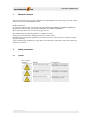
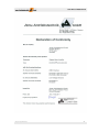
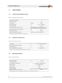
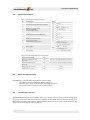
User Manual ECOSTEP®54 User Manual ECOSTEP®54 Published editions: Edition Comment Dec 2008 First English edition June 2009 Revision: Commissioning and parameterization with ECO Studio May 2011 Update of Declaration of Conformity Feb. 2012 Revision: Connection of holding brakes All rights reserved: Jenaer Antriebstechnik GmbH Buchaer Straße 1 07745 Jena No parts of this documentation may be translated, reprinted or reproducted on microfilm or in other ways without written permission by Jenaer Antriebstechnik GmbH. The content of this document has been worked out and checked carefully. Nevertheless differences from the real state of the hard and software can never be fully excluded. Necessary corrections will be carried out in the next edition. ECOSTEP® is a registered trademark of Jenaer Antriebstechnik GmbH, Jena. Windows® is a registered trademark of Microsoft Corporation in the United States and other countries. Subject to change without notice! 3 User Manual ECOSTEP®54 4 Subject to change without notice! User Manual ECOSTEP®54 Contents 1 About this manual ......................................................................................................................... 7 2 2.1 2.2 2.3 2.4 2.5 2.6 Safety instructions ......................................................................................................................... 7 Symbols ......................................................................................................................................................... 7 General notes ................................................................................................................................................ 8 Dangerous voltages ...................................................................................................................................... 8 Danger by hot surfaces ................................................................................................................................ 8 Danger by unintentional mechanical movements ................................................................................... 8 Prescribed use ............................................................................................................................................... 9 3 3.1 3.2 3.3 3.3.1 3.3.2 Legal notes .................................................................................................................................... 9 Terms of delivery .......................................................................................................................................... 9 Liability .......................................................................................................................................................... 10 Standards and directives ............................................................................................................................. 10 UL/CSA compliance acc. to UL 508C ....................................................................................................... 10 CE compliance .............................................................................................................................................. 10 4 4.1 4.2 4.3 4.4 4.5 4.6 Technical Data ............................................................................................................................. 12 Technical data of the power stage .............................................................................................................. 12 Electrical connection data........................................................................................................................... 12 Operating Conditions.................................................................................................................................. 12 General technical data ................................................................................................................................. 13 Betriebsarten ................................................................................................................................................. 13 Suitable types of motors ............................................................................................................................. 13 5 5.1 5.1.1 5.1.2 5.1.3 5.2 5.2.1 5.2.2 Installation ................................................................................................................................... 14 Mounting ....................................................................................................................................................... 14 Important notes ........................................................................................................................................... 14 Dimensions ................................................................................................................................................... 14 Assembly ....................................................................................................................................................... 15 Electrical Installation ................................................................................................................................... 16 Important notes ............................................................................................................................................ 16 EMC compliant installation ........................................................................................................................ 16 6 6.1 6.2 6.2.1 6.2.2 6.2.3 6.3 6.3.1 6.3.2 6.4 6.5 Interfaces ...................................................................................................................................... 17 Arrangement of the interfaces .................................................................................................................... 17 Control signals.............................................................................................................................................. 18 X5: Digital outputs, 24 V ............................................................................................................................. 18 X10: Digital inputs ....................................................................................................................................... 19 X9: Analog inputs, analog output .............................................................................................................. 20 Power connection......................................................................................................................................... 21 X1 to X4: Motor connector ......................................................................................................................... 21 X11: Supply voltage ...................................................................................................................................... 22 X8: RS232 interface ...................................................................................................................................... 23 X7: CAN interface ........................................................................................................................................ 24 7 7.1 7.2 7.3 7.3.1 Commissioning ............................................................................................................................ 25 Notes before commissioning ...................................................................................................................... 25 Control and display elements ..................................................................................................................... 25 Work schedule commissioning .................................................................................................................. 26 Error case ...................................................................................................................................................... 36 Subject to change without notice! 5 User Manual ECOSTEP®54 8 Accessories ................................................................................................................................... 37 8.1 Supplementary parts .................................................................................................................................... 38 8.1.1 Heat sink........................................................................................................................................................ 38 9 Annex ........................................................................................................................................... 39 9.1 Flowcharts for PLC programming 9.1.1 Homing.......................................................................................................................................................... 39 9.1.2 Operation mode 1 (Profile Positioning Mode): Direct absolute positioning (effective immediately) ................................................................................................................................ 40 9.1.3 Operation mode 1 (Profile Positioning Mode): Absolute positioning after setting the control word ........................................................................................................................................... 41 9.1.4 Operation mode 1 (Profile Positioning Mode): Relative positioning ................................................... 42 9.1.5 Operation mode 3 (Profile Velocity Mode) .............................................................................................. 43 9.2 Data Protocol of the RS232 Interface ........................................................................................................ 44 9.2.1 Download Request (Data Transfer from Host to Slave) ......................................................................... 45 9.2.2 Upload Request (Data Transfer from Slave to Host) ............................................................................... 46 9.3 Glossary ......................................................................................................................................................... 47 9.4 Index of standards and directives .............................................................................................................. 48 6 Subject to change without notice! User Manual ECOSTEP®54 1 About this manual This user manual describes the stepper amplifier series ECOSTEP®54. It concerns all persons who install, commission and operate ECOSTEP®54 drives. Further information: Operation using ECO Studio: „ECO Studio Operation Manual ECOVARIO®, ECOSTEP®, ECOMPACT®“ Programming: manual „Object Dictionary ECOVARIO®, ECOSTEP®, ECOMPACT®“ Motor data: Data sheets series 17S and 23S (stepper motors). This manual makes the following demands on qualified personnel: Transport: Personnel trained in handling electrostatic sensitive devices Installation: Electrotechnically qualified personnel who know the security directives of electrical engineering and automation Setup/Commissioning: Qualified personnel with a broad knowlege of the fields of electrical engineering, automation and drives. 2 Safety instructions 2.1 Symbols Table 2.1: Symbols Pictogram Subject to change without notice! Warning Consequences General warning about danger Disregarding this warning may lead to death or serious injuries. Warning about dangerous electrical voltages Disregarding this warning may lead to death or serious injuries. Warning about hot surfaces Disregarding this warning may lead to burns to the skin. 7 User Manual ECOSTEP®54 2.2 General notes Only properly qualified personnel are permitted to perform activities such as transport, installation, commissioning and maintenance of the ECOSTEP®54. The manufacturer of the machine must generate a hazard analysis for the machine and take appropriate measures to ensure that unforeseen movements cannot cause injury or damage to any person or property. In case of modifications or retrofits with components of manufacturers other than Jenaer Antriebstechnik, please contact us to clarify that those components are suitable to be assembled with our devices. Emergency-off equipment must be workable in all operation modes, especially during setup and maintenance. 2.3 Dangerous voltages Never open the units during operation. Covers and cabinet doors have to be kept closed during operation. The protective earth conductor has to be properly applied before applying a voltage. During operation logic and power conductors are live. Never undo electrical connections while they are live! After disconnecting the device wait at least 3 minutes before touching contacts. Capacitors can still have dangerous voltages present up to 3 minutes after switching off the supply voltage. To be sure measure the DC link circuit and wait till it has fallen below 40 V. 2.4 Danger by hot surfaces Hot surfaces may cause burns to the skin. As the housing of the ECOSTEP®54 serves also as heat sink during operation the surface temperature may rise to more than 70 °C. 2.5 Danger by unintentional mechanical movements Unintentional movements of motors, tools or axes may lead to death or serious injuries. ECOSTEP®54 drives can produce strong mecanical powers and high accelerations. Avoid staying in the danger zone of the machine. Never switch off safety equipment! Malfunctions should be repaired by qualified personnel immediately. 8 Subject to change without notice! User Manual ECOSTEP®54 2.6 Prescribed use The stepper motor amplifiers ECOSTEP®54 are components which are built into electrical equipment or machines and can only be used as integral components of such equipment. All notes about technical data and ambient conditions have to be observed. Using the unit in hazardous locations and in ambients containing oil, gas, vapours, dusts, radiations etc. is prohibited if it is not explicitly allowed. The manufacturer of the machine must generate a hazard analysis for the machine and take appropriate measures to ensure that unforeseen movements cannot cause injury or damage to any person or property. If one or more servo amplifiers ECOSTEP®54 are built into machines or plants the intended operation of the servo amplifier is forbidden until it has been established that the machine or plant fulfills the requirements of the EC Machinery Directive 2006/42/EC and the EMC Directive 2004/108/EC. Further EN 60204 and EN ISO 12100 parts 1 and 2 have to be observed. 3 Legal notes 3.1 Terms of delivery Our terms of delivery are based on the „The General Terms of Delivery for Products and Services of the Electrical Industry“ (German: ALB ZVEI) of the Central Association of the Electrical and Electronics Industry (ZVEI e.V.) in their current version. Subject to change without notice! 9 User Manual ECOSTEP®54 3.2 Liability The circuits and procedures in this manual are proposals. Every user has to check the suitability for every special case. Jenaer Antriebstechnik GmbH is not responsible for suitability. Especially Jenaer Antriebstechnik is not responsible for the following damage causes: disregarding the instructions of this manual or other documents concerning ECOSTEP®54 unauthorized modifications of drive, motor or accessories operating or dimensioning faults Improper use of the ECOSTEP®54 components 3.3 Standards and directives Stepper motor amplifiers ECOSTEP®54 are components intended to be built in machines or plants for industrial purposes. ECOSTEP54 complies to the standards and directives listet in the appendix, chapter 9.4. 3.3.1 UL/CSA compliance acc. to UL 508C The stepper motor amplifiers ECOSTEP 54 are designed in compliance with UL or cUL respectively. For further information see UL file number E244038 at www.ul.com. 3.3.2 CE compliance Stepper motor amplifiers ECOSTEP®54 are components that are intended to be built into electrical plant and machines for industrial use. The manufacturer of the machine is responsible that the machine or plant fulfills the requirements of the EMC directive. The stepper motor amplifiers ECOSTEP®54 have been tested by an authorized testing laboratory in a defined configuration with the system components which are described in this documentation. Any divergence from the configuration and installation described in this manual means that you will be responsible for carrying out new measurements to ensure that the regulatory requirements are fulfilled. 10 Subject to change without notice! User Manual ECOSTEP®54 Subject to change without notice! 11 User Manual ECOSTEP®54 4 Technical Data 4.1 Technical data of the power stage Table 4.1: Technical data of the power stage Number of motor outputs Max. phase currrent 4 A 2.5 Step resolution Steps/rev. Max. output voltage VDC UDC-BUS , cf. table 4.2 12,800 4 x 100 Max. output power W Short-circuit strength of motor output current limiting in case of short circuit of motor phases against each other and against UDC-BUS Minimum inductance of motor winding mH Length of motor cable m Frequency of output current ripple dependent on current and inductance min. 1 max. 10* *) Please consult our application department in case of longer cables. 4.2 Electrical connection data Table 4.2: Electrical connection data Logic supply VDC Protection required for logic supply A Power supply (UDC-BUS) VDC Protection required for power supply A 20 ... 30, max. 200 mA 3T 24 ... 45 10 slow-acting* *) if required, use an UL-certified automatic circuit breaker 10 A, 60 VDC slow-acting 4.3 Operating Conditions Table 4.3: Operating conditions Ambient temperature °C 0 ... + 40 Storage temperature °C - 10 ... + 70 Air humidity (non-condensing) 5 ... 95% (RH-2 acc. to IEC 61131-2) Pollution severity 2 acc. to IEC 61131-2 Protection class IP20 Mounting position vertical Installation altitude up to 1000 m above mean sea level w/o restriction Power loss: if 4 axes traverse with 2.5 A W approx. 30 Cooling by means of convection. Heat sink required in case of restricted convection. 12 Subject to change without notice! User Manual ECOSTEP®54 4.4 General technical data Table 4.4: General technical data: control signals No. Control signal 1 24 V supply (current draw without outputs) 8 Unit Digital control signal inputs (user-programmable, or as limit switch inputs) 1 Control signal DC link relay (REL+, REL-) 8 Digital control signal outputs (4 user-programmable, 4 resereved for holding brakes) VDC A 24 ±10 % 0.8 VDC LOW 0 – 4, HIGH 13 – 30 mA 3.4 / 2.4 (at 24 VDC) kΩ 7 VDC 20 ... 24 mA 50 VDC 24 (20 ... 30) A 0.5 Holding brake: max. 0.8 / 0.4 A (100 ms / continuous) 0 V ... +5 V, 10 bit resolution 4 Analog inputs 1 Analog output kΩ at DC: R > 250 at f > 250 Hz: R < 15 -10 V – +10 V, 8 bit resolution Table 4.5: General technical data: dimensions and weight 4.5 Dimensions and weight Unit Dimensions without heat sink (w x h x d) mm 240 x 62 x 170 (without mating connector) Dimensions with heat sink (w x h x d) mm 240 x 102 x 170 (without mating connector) Weight (without heat sink) kg 1.8 kg Weight (with heat sink) kg 3.4 kg Modes for setpoint setting ECOSTEP®54 provides the following modes for setpoint setting: Online positioning via field bus (RS232, CANopen) Positioning control via SPS interface (digital inputs/outputs) Joystick operation (analog inputs, resolution 10 bit). 4.6 Suitable types of motors With ECOSTEP®54 stepper motor amplifier various types of stepper motors can be operated, among others the stepper motor series 17S und 23S of Jenaer Antriebstechnik GmbH. Technical data and regulations in this manual only refer to these motors. Technical data of the motors can be retrieved from the motor data sheets or from our homepage www.jat-gmbh.de. Subject to change without notice! 13 User Manual ECOSTEP®54 5 Installation 5.1 Mounting 5.1.1 Important notes Make sure that transport and storage did no damage to the units. The ambient air must not be polluted by dust, greases, aggressive gas etc. Eventually appropriate countermeasures have to be taken (installation of filters, frequent cleaning). Depending on the power losses an appropriate ventilation should be provided. Observe the mounting spaces. At installation locations with permanent vibrations or shocks damping measures should be taken into consideration. The device contains electrostatic sensitive devices which can be damaged by improper usage. 5.1.2 Dimensions 180 240 170 62 Fig. 5.1: Dimensions of ECOSTEP®54 [mm] 14 Subject to change without notice! User Manual ECOSTEP®54 5.1.3 Assembly When mounting the ECOSTEP®54 into the cabinet cable clamps (contained in connector kit AMK40, cf. chap. 8) assure that the connecting cables are laid EMC conform by connecting the cable shield extensively to chassis earth. Maximum cable diameter is 15 mm. It is important that the air flow is not disturbed by components above or below the stepper motor amplifiers. If a heat sink is used (cf. chap. 8.1.1), the mounting space will increase by 40 mm. The surface of the mounting plate has to be conductive (e.g. zinc plated). Varnished mounting plates must not be used. To calculate the minimal mounting depth (fig. 5.3, dim A) the form of the connectors (cable outlet direction) and the minimum bending radii of the connecting cables at the sub-D connectors have to be regarded. Cable conduct Mounting plate with conductive surface Cubicle door 30 A 170 30 240 Cylindric screw M5 DIN912 65 65 105 Cable conduct Fig. 5.3: Mounting dimensions cabinet, width and depth [mm] Subject to change without notice! 15 User Manual ECOSTEP®54 5.2 Electrical Installation 5.2.1 Important notes All installation work may only be carried out if the machine or plant is not live and protected against restart. Never exceed the maximum rated voltage at the connector X11 (power supply) X11! Umax = 45VDC The guarding of the DC supply and the 24 V logic voltage should be carried out by the user Stepper motor amplifier and motor have to be properly grounded. The protective earth conductor must have at least the same diameter as the supply cables. The stepper motor amplifier should be mounted onto a conductive (not varnished) metal mounting plate. 5.2.2 EMC compliant installation The supply connection of the machine should be equipped with an appropriate RFI suppression filter. Always use shielded cables. Metal parts in the cabinet have to be interconnected extensively and and be conductive regarding HF. Used relays, contactors, solenoids etc. have to be protected against overvoltage. Supply cables and motor cables must be laid in a proper distance of control cables. 16 Subject to change without notice! User Manual ECOSTEP®54 6 Interfaces 6.1 Arrangement of the interfaces X1 - X4: Stepper motor connector 1 ... 4 Status LEDs X7: CAN interface X8: RS232 interface X9: Analog inputs/outputs X5: Digital outputs X10: Digital inputs X11: Power supply Fig. 6.1: Arrangement of the ECOSTEP®54 interfaces A mating connector for interface X11 (socket connector 6-pole, WAGO type 231-306) is contained in the connector kit SMK40 (siehe Kap. 9). Note: The width of the of the D-Sub mating connector handle must not exceed 31.5 mm. (e.g. Harting type 09 67 009 0443). Subject to change without notice! 17 User Manual ECOSTEP®54 6.2 Control signals The control signals are programmable (cf. manual „Object Dictionary ECOVARIO® + ECOSTEP®“). 6.2.1 X5: Digital outputs, 24 V Table 6.1: Pin assignment connector X5 Signal Pin OUT1 1 X5 Description Digital output 1 (PLC output), IO max = 0.5 A OUT2 2 Digital output 2 (PLC output), IOmax = 0.5 A OUT3 3 Digital output 3 (PLC output), IOmax = 0.5 A OUT4 4 Digital output 4 (PLC output), IOmax = 0.5 A OUT5 5 Digital output 5, reserved for holding brake motor 1* IOmax = 0.5 A OUT6 6 Digital output 6, reserved for holding brake motor 2* IOmax = 0.5 A OUT7 7 Digital output 7, reserved for holding brake motor 3* IO max = 0.5 A OUT8 8 Digital output 8, reserved for holding brake motor 4* IO max = 0.5 A O24V 9 24 V supply voltage for digital outputs. Also supplies holding brake outputs on X1 ... X4 . OGND 10 24 V ground OUT 1 OUT 2 OUT 3 OUT 4 OUT 5 OUT 6 OUT 7 OUT 8 O24V OGND Fig. 6.2: Connector X5: 10-pole cage clamp terminal (cable diameter max. 0,752) *) Holding brake output in parallel to X1 ... X4 (cf. chap. 6.3.1). If no holding brake is used, OUT5 ... OUT8 can be used as free programmable digital outputs. Settings via ECO Studio, cf. chap. 7.3, item 9. +24 V X5 Control 1 OUT1 +24 V Load res. 2 OUT2 +24 V Load res. 3 OUT3 Load res. +24 V ... ... 8 OUT8 +24 V Galvanic isolation GND +24 V 9 +24 V 10 GND Load res. + External power supply 24 V DC ECOSTEP 54 Fig. 6.3: Connector X5: Circuit of the digital outputs 18 Subject to change without notice! User Manual ECOSTEP®54 6.2.2 X10: Digital inputs Tabelle 6.2: Pin assignment connector X10 X 10 Signal Pin Description DIN1 1 Digital input 1 DIN2 2 Digital input 2 DIN3 3 Digital input 3 DIN4 4 Digital input 4 DIN5 5 Digital input 5 DIN6 6 Digital input 6 DIN7 7 Digital input 7 DIN8 8 Digital input 8 n.c. 9 n.c. IGND 10 external 24V ground DIN1 DIN2 DIN3 DIN4 DIN5 DIN6 DIN7 DIN8 n.c. IGND Fig. 6.4: Connector X10: 10-pole cage clamp terminal (cable diameter max. 0,752) Digital inputs can be used e.g. for limit position switches X10 1 Control 24V DIN1 Control signal IGND 2 DIN2 Control signal IGND 3 ... IGND 8 DIN3 ... Control signal DIN8 Control signal 24V IGND Galvanic isolation IGND 9 10 n.c. IGND + External power supply 24V= ECOSTEP 54 Fig. 6.5: Connector X10: Circuit of the digital inputs Subject to change without notice! 19 User Manual ECOSTEP®54 6.2.3 X9: Analog inputs, analog output Table 6.3: Pin assignment connector X9 Signal Pin Description Value AN0 1 Analog input 1 0 ... 5 V AN1 2 Analog input 2 0 ... 5 V AN2 3 Analog input 3 0 ... 5 V AN3 4 Analog input 4 0 ... 5 V GND 5 Internal GND +5V 6 Internal 5-V-supply n.c. 7 n.c. DA0 8 Analog output GND 9 Internal GND 1k GND 7 2 8 3 9 4 5 Fig. 6.6: Mating connector X9: 9-pole D-Sub connector, View of the solder or crimp side +/- 10 V 6 +5V +5V 1 max. load 20 mA, unprotected! X9 Power supply 6 Control +5V +5V +5V 1 AN0 10k ... +5V ... +5V ... GND 4 AN3 10k 5 GND GND GND 880k 0...5V DAC ECOSTEP 54 220k 2V + 8 DA0 Analog value 9 GND GND GND Fig. 6.7: Connector X9: Circuit of the analog inputs and the analog output 20 Subject to change without notice! User Manual ECOSTEP®54 6.3 Power connection 6.3.1 X1 to X4: Motor connector Table 6.4: Pin assignment connectors X1 to X4 Signal Pin Description Phase A 4 Stepper motor connection Phase /A 3 Stepper motor connection Phase B 2 Stepper motor connection Phase /B 1 Stepper motor connection +24 V 5 Limit position switch supply Brake + 6 Holding brake connection (+) Limit position + 7 PLC input limit position + Brake - 8 Holding brake connection (-) Limit position - 9 PLC input limit position - Shield shroud connected to GND via housing 6 1 7 2 8 3 9 4 5 Fig. 6.8: Mating connector X1 to X4: 9-pole D-Sub connector, View of the solder or crimp side Fig. 6.9: Motor connection Note: For power supply of the holding brakes a voltage of + 24 V has to be applied to X5, between Pin 9 (+ 24V) and Pin 10 (GND). Subject to change without notice! 21 User Manual ECOSTEP®54 6.3.2 X11: Supply voltage Table 6.5: Pin assignment connector X11 Signal Pin Description 24 V logic supply +24V Incoming supply voltage +20 ... 30VDC / max. 0.2 A GND GND GND for logic supply DC link relay + REL+ Switching on the DC link DC link relay - REL - Switching on the DC link Power supply + + DC BUS Incoming supply +24V...45VDC / max. 8 A GND GND GND for power supply Fig. 6.10: Connector X6: 6-pole cage clamp terminal, max. cable diameter 1.52 Appropriate power supply modules for stepper motor amplifier ECOSTEP®54 from the program of Jenaer Antriebstechnik: Power supply 24 V: switch-mode power supply ML70.100, Puls GmbH, 3 ... 5A Power suppy 45 V: switch-mode power supply SL10.101, Puls GmbH, 48 V, limit to 45 V. Switching on the DC link The DC link is switched on by applying a voltage of +24VDC across REL+ und REL-. 2-phase powerstage X11 Supply 24 V +24V Supply GND GND DC bus relay + REL + DC bus relay - REL - DC bus + +DC BUS DC bus GND GND 24 VDC 5 VDC 24.. 45 VDC Fig. 6.11: Connector X11, circuit Line filter The user has to make sure to conform to the regulations of the EMC Directive (2004/108/EC) by appropriate measures (external line filter, EMC compliant wiring). Fusing For external fusing please consider the general technical data (cf. chapter 4.2). 22 Subject to change without notice! User Manual ECOSTEP®54 6.4 X8: RS232 interface The stepper motor amplifier ECOSTEP®54 can be completely programmed and parameterized by a PC via the RS232 interface. The connector X8 provides a pinout for direct cabling to a standard PC COM interface. Fat drawn wires are necessary for communication, other wires are for handshaking simulations for special PC programs. The transceiver inside ECOSTEP®54 meets the EIA-232E and CCITT V.28 specifications and provides ESD protection to IEC1000-4-2 (801.2). Table 6.7: Pin assignment connector X8 R232 interface Pin Signal Description 1 - n.c. 2 TxD RS232 TxD 3 RxD RS232 RxD 4 - n.c. 5 GND Digital ground 6 - n.c. 7 - n.c. 8 - n.c. 9 - n.c. shroud Shield connected to GND via housing 6 1 RTS CTS RI 3 9 4 5 ECOSTEP 54 X8 D-Sub 9-pole male DTR GND DSR 2 8 Fig. 6.12: Mating connector X8: 9-pole D-Sub connector, View of the solder or crimp side PC COM DCD RxD TxD 7 1:1 cabling D-Sub 9-pole female 1 2 1 2 3 3 4 4 5 from transmitter to receiver 5 6 6 7 7 8 8 9 9 Fig. 6.13: Lines necessary for RS232 communication The communication protocol provides network operation of up to 15 ECOSTEP®54 devices working as communication slaves in a mono master network. In that case the RS232 cabling must have a loop structure as follows: RxD GND TxD Hostcomputer 3 5 2 X8 ID=1 R ECOSTEP 54 3 5 2 X8 ID=2 R ECOSTEP 54 3 5 2 X8 ID=n R ECOSTEP 54 Fig. 6.14: RS232 network as loop structure Subject to change without notice! 23 User Manual ECOSTEP®54 6.5 X7: CAN interface Die CAN interface of the ECOSTEP®54 is based on the communication profile CiA DS 301 and the device profile CiA DSP 402 (drives and motion control). 9 8 7 6 It must be supplied with an external voltage. 5 4 3 2 1 Terminating resistors for busses are not built in the ECOSTEP®54. A CAN bus has to be terminated with a 120 Ω resistor at the beginning and at the end. If Fig. 6.15: Mating connector X7: 9-pole D-Sub socket; View of the ECOSTEP®54 is operated as first or last participant at a CAN bus, it is use- the solder or crimp side ful to solder the terminating resistor in the mating connector of X7 between the pins 2 and 7. The manual „Object Dictionary ECOVARIO® and ECOSTEP®“ Table 6.8: Pin assignment connector X7 contains a detailed description of all available functions. Pin Signal Description The Baud rate und the device ID can be set via the 1 n.c. appropriate CAN objects. By default the ID is set to 1. The following baud rates are supported: 1 000 kBit/s, 500 kBit/s, 250 kBit/s, 125 kBit/s, 100 kBit/s, 50 kBit/s. If point of sampling and scan rate (86.7 %, 3-times sampling at all Baud rates) do not meet the demands please get in touch with the technical service of Jenaer Antriebstechnik. 2 CAN_L CAN data L 3 CAN_GND reference potential to CAN data 4 - n.c. 5 - n.c. 6 CAN_GND reference potential to CAN_V+ 7 CAN_H CAN data H 8 - n.c. 9 CAN_V+ +8 ... + 18 VDC, max. 50 mA Fig. 6.16: Circuit X7 CAN interface CAN_H 7 7 7 7 2 2 2 2 9 9 9 9 3 3 3 3 R CAN_L CAN_V+ CAN_GND Master in CAN-Bus R X7 Axis 1-4 X7 Axis 5-8 X7 Axis 9-12 X7 Axis n Fig. 6.17: Dimensioning terminating resistors R depending on line impedance; default: R = 120 Ω 24 Subject to change without notice! User Manual ECOSTEP®54 7 Commissioning 7.1 Notes before commissioning Only qualified personnel with a broad knowlege of the fields of electrical engineering, automation and drives are allowed to commission the stepper motor amplifier ECOSTEP®54. If required, Jenaer Antriebstechnik GmbH offers trainings. The manufacturer of the machine must generate a hazard analysis for the machine and take appropriate measures to ensure that unforeseen movements cannot cause injury or damage to any person or property. Check the wiring for completeness, short circuits and ground fault. All live parts must be protected safely against touching. Never pull the connectors while they are live! If there are several axes in one machine commission one axis after the other. The axes already commisioned should be switched off. During operation the temperature of the heat sink and the housing may rise up to over 70 °C. Before touching these parts after switching off the unit wait until the temperature has fallen down to 40 °C. 7.2 Control and display elements At the front side of the ECOSTEP®54 4 LEDs are located which display status and error messages: LED „24V“ (green) on: +24 V logic supply applied LED „BUS“ (green), communication display: On, if the first character of a telegram has been received. Goes out as soon as the telegram is processed completely. LED „RUN“ (green) flashes: software running, stepper motor amplifier ready for operation LED „ERR“ (red) on: error message, cf. chap. 7.3, step 4. Subject to change without notice! 25 User Manual ECOSTEP®54 7.3 Work schedule commissioning 1. Check installation The stepper motor amplifier is disconnected from the supply. Check the wiring for completeness, short circuits and ground faults. For commissioning an RS232 connection via a 1:1 cable from socket X8 to COM1 or COM2 of a PC is required. On PC side also a USB interface can be used. In this case the ECO2USB cable has to be applied, which is available as an accessory (cf. chap. 8). 2. Switch off DC link relay At the socket X11 no voltage must be applied between the pins REL+ and REL-. 3. Switch on 24 V supply Apply the 24 V logic supply at the connector X11 between the pins GND and +24 V; after an initializing phase of about 3 s the LEDs show the operation mode of the stepper motor amplifier. Normally, the green LED „RUN“ flashes and the green LED „24V“ is on. If this is not the case, check again the logic supply and reset the stepper motor amplifier by switching off and on again the logic supply. 4. Rectify eventual errors If the LEDs show an error, i.e. the red „ERR“ LED is on, the error has to be rectified before commissioning. Possible error causes: Power supply voltage too low (< 15 V) Heat sink temperature too high (> 80 °C) internal controller error For further information on the proceeding in case of an error refer to chap. 7.3.1. 5. Start setup software Install the commisioning and operation software ECO Studio provided on the adjoined CD-ROM to a PC (for the system requirements please refer to the ECO Studio manual). Connect a PC to the RS232 interface of the ECOSTEP®54 and start ECO Studio. For the operation of ECO Studio please observe the online documentation or the ECO Studio Operation Manual, respectively. Context sensitive help is also provided via the F1 key. 6. Communication PC - ECOSTEP54, device address After ECO Studio has been started, the Communication: Connect/Disconnect window is shown. In the Interface selection list box select the RS232 interface. In the Parameters group box, specify the serial interface of the PC used for the connection (default: COM1) and the baud rate (default: 9600 Baud). Click the connect button in order to establish the connection. 26 Subject to change without notice! User Manual ECOSTEP®54 Fig. 7.1: Communication: Connect/Disconnect window ID: The device address (ID) of an ECOSTEP54 is adjusted to 1 by default and results from the sum of object „node-ID“ (Ox100B,00) and object „node-offset“ (Ox2F80,00). The ID can only be changed via the object „node-offset“ (default=0), as the object „node-ID“ is predefined to 1 and cannot be changed. IDs in the range 1 ... 127 can be assigned, whereas each ID must only be assigned once in one network. If you wish to modify the address, first set the „node_offset“ accordingly. After that the new value has to be stored permanently. The new address is then assigned after the +24 V logic supply is switched on again. Each device communicates also via the „Joker-ID“=127 (7Fh), independent of the ID adjusted at the given instant of time, so that even in the event of a false or unknown configuration a single device can be accessed. 6. Set parameters The parameters have to be adjusted to each individual application. Incorrect parameter settings can cause damage or destruction of machine parts. The correct setting of the following parameters is especially important. The settings can be done for all 4 motor outputs (Axis 1 to Axis 4) via the navigation area item Output Mode -> Stepper Motor: Subject to change without notice! 27 User Manual ECOSTEP®54 Fig. 7.2: Parameter settings for motor and holding brake: Window „Output Mode -> Stepper Motor“ Maximum Current: maximum motor current -> please take from motor data sheet. Holding Current: phase current at standstill -> please take from motor data sheet. Additional Travel Current: run current effective in addition to the phase current at standstill -> please take from the motor data sheet. Resolution: step resolution per motor pole -> please take from motor data sheet (Example: step resolution 256 at 50-pole motor results in 12800 steps/resolution). Switch Velocity: Velocity value at which switching from sine to rectangular commutation takes place. By switching from sine to rectangular commutation an increase of the torque value is achieved, because at rectangular commutation the motor characteristic can be fully utilized. Unit is mm/s. At the value 0 sine commutation is activated. Start/Stop Velocity: Velocity after the target position has been reached, normally = 0. Note: The resulting motor current is limited to the Maximum Current in any case, even if the sum of Holding Current and Additional Travel Current exceeds the Maximum Current. 7. Check safety equipment Before switching on the voltage it is vital to check if all safety equipment that protects from touching live parts and from the consequences of indeliberate movements functions properly. 28 Subject to change without notice! User Manual ECOSTEP®54 8. Configure limit position switches If the limit position switches at the motor connection X1 ... X4 shall not be used, the limit positions can be configured under Inputs/Outputs -> Digital Inputs. Fig. 7.3: Configuring the limit position switches in the „Digital Inputs“ window Table 7.1: Parameters and possible settings of digital inputs and limit position switches Parameter Description Window area Inputs Invert If the check box is checked, the applied digital input signal is inverted. I.e., the input is set to „active“ by a LOW-level signal (without inverting the signal a HIGH level sets the input). Status State of the digital inputs: grey = inactive, green = active Windows area Limit Switch Configuration It can be specified whether the digital inputs DIN1 to DIN8 or the inputs at the motor connectors should be used as limit position inputs. If DIN1 to DIN8 should be used, the respective check boxes have to be checked. The inputs at the motor connectors are galvanically not isolated. DIN1 corresponds to positive limit position axis 1 DIN2 corresponds to negative limit position axis 1 DIN3 corresponds to positive limit position axis 2 DIN4 corresponds to negative limit position axis 2 DIN5 corresponds to positive limit position axis 3 DIN6 corresponds to negative limit position axis 3 DIN7 corresponds to positive limit position axis 4 DIN8 corresponds to negative limit position axis 4 Invert If the connected limit position switch works as a normally open contact: do not set check box If the connected limit position switch works as a normally closed contact: set check box Status Green: A limit position event occured: Limit position switch has been triggered and limit position detection is activated in the stepper motor amplifier. Use for Limit Position It can be specified whether for the detection of the respective limit position a limit position switch us used. Subject to change without notice! 29 User Manual ECOSTEP®54 9. Configure holding brake If the holding brake shall be connected alternatively to connector X5 OUT5 ... 8, the mapping of the respective output has to be set to object 0x21240020. AndMask and CmpMask specify the respective output. The settings are done under Inputs/Outputs -> Digital Outputs 5...8. Fig. 7.4: Configuring the holding brake in the window „Digital Outputs 5...8“ 10. Switch on power supply 11. Switch on DC link circuit 0,5 s after switching on the power supply the DC link circuit relay can be switched on. Therefore, a voltage of + 24V has to be applied across pins REL+ and REL - of connector X11. 12. Set „Switch On“ bit in the control word The drive is switched on by software. Click the Switch on Device button in the left area of the main window. ECOSTEP54 is controlled via the control word and the status word. Under Device Status, the bits of both are displayed for each axis separately and the control word can be modified. 30 Subject to change without notice! User Manual ECOSTEP®54 Fig. 7.5: Control word and status word in the „Device Status“ window 13. Set „Enable Operation“ bit in the control word The drive is ready now for further commands. The drive can be switched off any time by resetting the „Operation enable“ bit. 14. Carry out homing procedure The homing procedure can be carried out according to the following methods. The homing method is selected under Motion -> Homing: Table 7.2: Homing methods of ECOSTEP54 Value Description 17 Homing to the negative limit position 18 Homing to the positive limit position 34 Homing to the actual position Subject to change without notice! 31 User Manual ECOSTEP®54 Fig. 7.6: Homing settings The following homing parameters can be set in the window: Table 7.3: Homing parameters at ECOSTEP54 Parameter Description Zero Shift After homing has been finished the home position can be shifted with this parameter. Reference Switch Search Velocity Velocity of the search travel for the reference switch [mm/s] Reference Point Search Velocity Velocity of the search travel for the home position [mm/s] Homing Acceleration Acceleration and deceleration during the homing process [mm/s2] Homing is started with the specified parameters by clicking the Start Homing button. As soon as the reference has been found, „Reference found“ is displayed in the message area. In the window area Device Status the Referenced box is displayed in green colour. Homing can be interrupted by clicking the Stop Homing button. For PLC programming of the homing procedure you find a flowchart in the Annex (Chap. 9.1). 32 Subject to change without notice! User Manual ECOSTEP®54 15. Select operation mode Besides homing the following operation modes can be selected for the ECOSTEP54 in the navigation area under Motion: Positioning Mode Velocity Mode. In the Positioning Mode the following parameters can be configured for the 4 controlled axes in the navigation area under Motion -> Positioning Mode (switching between the axes is done via the menu item ECOSTEP54): Fig. 7.7: Operation mode Positioning Mode The parameters are described in the following table. Table 7.4: Parameters in Positioning Mode for ECOSTEP54 Parameter Description Target Position A target position is specified. The value can be entered either absolute or relative to the actual position with a resolution of 0,1 µm. The entered value becomes only valid when Start has been clicked. Profile Velocity Target velocity within the trapezoidal profile Actual Profile Velocity Actual target velocity within the trapezoid profile Acceleration Ramp Maximum acceleration within the trapezoidal profile in order to reach the target velocity Deceleration Ramp Maximum deceleration within the trapezoidal profile Subject to change without notice! 33 User Manual ECOSTEP®54 Position Window Specification of the position window (symmetrical value range around the target position). If the actual position is within the position window the „target reached“ flag is set in the status word. Positive Software Limit Pos. Limit position in positive direction, determined by the mechanics of the machine or by setting a positive software limit position. Negative Software Limit Pos. Limit position in negative direction, determined by the mechanics of the machine or by setting a negative software limit position. To start positioning mode with the selected parameters click the Start button. Background information: The positioning mode is controlled by means of 3 bits of the control word: Table 7.5: Control word in Positioning Mode for ECOSTEP54 Control word (binary) Description xxxx0xxxx The target position can be set without immediate positioning Transition from xx000xxx to xx001xxx The drive carries out an absolute positioning according to the defaults in the tab Positioning Mode. Transition from xx100xxx to xx101xxx The drive carries out a relative positioning according to the defaults in the tab Positioning Mode. xx011xxx New absolute target positions become effective immediately In the Velocity Mode the following parameters can be configured: Fig. 7.8: Parameters in the Velocity Mode The parameters are described in the following table. 34 Subject to change without notice! User Manual ECOSTEP®54 Table 7.6: Parameters in the Velocity Mode for ECOSTEP54 Parameter Description Target Velocity A target velocity is specified. The travel mode can be specified either with velocity profile by using the acceleration and deceleration ramps (selection profile) or without velocity profile (selection direct) and becomes valid by clicking the Start button. Actual Target Velocity Target velocity valid at the moment. Might deviate from the specification in the Target Velocity field if the Start button has not yet been clicked after a new value has been entered. Acceleration Ramp Maximum acceleration within the trapezoidal profile in order to reach the target velocity Deceleration Ramp Maximum decelaration within the trapezoidal profile Position Window Specification of the position window (symmetrical value range around the target position). If the actual position is within the position window the „target reached“ flag is set in the stauts word. Maximum Profile Velocity Velocity limit of the positioning. Depends on the mechanical characteristics ot the complete system. For PLC programming in positioning mode and velocity mode please refer to the flowcharts in the Annex (Chap. 9.1). Commissioning of the ECOSTEP®54 is now finished. Further configurable parameters (e.g. communication via CANopen) and sequence programming are described in detail in the ECO Studio help system and in the manual „Object Dictionary ECOVARIO®, ECOSTEP®, ECOMPACT®“. Subject to change without notice! 35 User Manual ECOSTEP®54 7.3.1 Error case If an error occurs the red „ERR“ LED on the front side of the ECOSTEP54 goes on and in the status word (Device Status) the „Fault“ bit is set. Fault conditions are evaluated individually for each axis and are displayed in the Device Errors tab at the bottom of the main window. Table 7.7: Error messages in the „Device Errors“ window Error Message Measures Internal controller error Try to reset the fault condition (see below). If no success, replace device Heat sink temperature too high (> 80 °C) Switch off device. Check heat dissipation. Power supply voltage too low (< 15 V) Check voltage Bus error Check bus connection and device function Note: Fault conditions always lead to the shutdown of the drive. After the error cause has been fixed, fault conditions can be reset. After that, the red „ERR“ LED should go out and the„Fault“ bit in the status word should not be set. Otherwise, a fault condition is still present after the reset attempt. Before the drive can be switched on again, the „Switch On“ bit in the control word has to be reset and then set again. In the navigation area under Option Codes the behaviour of the drive in case of shutdown, Quick Stop and fault conditions is specified: Fig. 7.9: Specifying the behaviour of the drive in case of quick stop, shutdown and fault conditions 36 Subject to change without notice! User Manual ECOSTEP®54 Table 7.8: Specifying the behaviour of the drive in case of quick stop, shutdown and fault conditions Name Description Behaviour in case of „Quick Stop“. Note: Default setting is the switching-off of the drive in case of quick stop. The axis coasts down without controlled braking. Quick Stop Especially with vertical axes (z axes) make sure that the quick stop ramp is configured with a sufficient deceleration (c.f. Braking Effect). If the quick stop ramp is configured too flat, movements could occur with high velocity towards the lower limit position in case of quick stop. Options 0: Drive is switched off and axis coasts down, no braking ramp (default setting) 1: Slow down on slow down ramp (normal braking case) until standstill, drive is switched off and the motor is free to rotate 2, 3, 4: Slow down on quick stop ramp, drive is switched off and axis rotates freely 5: Slow down on slow down ramp, drive stays in quick stop 6, 7, 8: Slow down on quick stop ramp, drive stays in quick stop Shutdown Behaviour of the servo amplifier at the transition OPERATION ENABLE -> READY TO SWITCH ON, i.e. Bit 0 of the control word is set to 0. 0: Drive is switched off and axis coasts down (default setting) 1: Slow down on slow down ramp, drive function is switched off and locked Disable Operation Behaviour of the servo amplifier at the transition OPERATION ENABLE -> SWITCHED ON, i.e. Bit 3 of the control word is set to 0. 0: Drive is switched off and and axis coasts down (default setting) 1: Slow down on slow down ramp, drive function is switched off and locked Stop (Halt) Behaviour of the servo amplifier if bit 8 of the control word is set to 1. Fixed setting is that drive is switched off and the motor is free to rotate. Behaviour of the servo amplifier if a fault occurs in the drive. Guarantees a controlled stop of the drive in case of a fault. Fault Especially with vertical axes (z axes) make sure that the quick stop ramp is configured with a sufficient deceleration (c.f. Braking Effect). If the quick stop ramp is configured too flat, movements could occur with high velocity towards the lower limit position in case of quick stop. 0: Drive is switched off and axis coasts down, no braking ramp (default setting) 1: Slow down on quick stop ramp until standstill, drive is switched off and the motor is free to rotate 2, 3, 4: Slow down on slow down ramp until standstill, drive is switched off and the motor is free to rotate 0: Sending out an emergency telegram only (default setting) 1: Communication error is set and displayed, drive is switched off without slow down ramp and motor is free to rotate. 2: Drive is switched off immediately, motor is free to rotate, no error display, no emergency telegram 3: Behaviour as specified in the Quick Stop selection list box 4: Function disabled (no action) Abort CAN Connection Behaviour of the servo amplifier if the CAN connection is aborted. Used with faults in the synchronous mode and in nodeguarding. Slow Down Ramp Setting the deceleration for the slow down ramp (normal braking case) Quick Stop Ramp Setting the deceleration for the quick stop ramp Limit Switch Used It can be specified whether for the detection of the respective limit position a limit position switch is used (concerning the assignment cf. Inputs/Outputs -> Digital Inputs) Subject to change without notice! 37 User Manual ECOSTEP®54 8 Accessories Table 8.1: Survey of ECOSTEP®54 accessories Order key Description Heat sink SMH41 Heat sink for ECOSTEP®54 with mounting elements Connector Kit SMK40 Socket connector 6-pole (WAGO type 231-306) as mating connector for X11 Strain relief bushing 20 mm and raised-head screw M3 x 12 (Strain relief and shield connection of the connection cables) Software tools CD with commissioning and parameterization software HWIN54 including documentation for ECOSTEP®54 Cables and adapters ECO2USB Adapter RS232 to USB, used for parameterization of the ECOSTEP®54 via the USB interface of the PC 8.1 Supplementary parts 8.1.1 Heat sink The heat sink set consists of: 1 heat sink SMH41 for ECOSTEP®54 6 screws M5x16 6 serrated lock washers 5,3 mm 6 x cylindrical screw M5x16 6 x serrated lock washer 5,3 mm Heat sink SMH41 ECOSTEP54 Fig. 8.1: Monting heat sink 38 Subject to change without notice! User Manual ECOSTEP®54 9 Annex 9.1 Flowcharts for PLC programming 9.1.1 Homing Flowchart homing for ECO54 axis, initial situation after power-on: control word = 0x0006, status word = 0x0031. For safety reasons every movement of an axis should be monitored by the PLC via timeout. Set modes_of_operation = 0x06 Start homing and timeout: control word = 0x001F yes Timeout? no Error no Reference found, status word = 0x9437 ? yes control word = 0x000F status word = 0x8437? no Error yes Homing finished successfully! The objects to be written or to be read, resp. for the individual axes are (incl. sub index and length): control word status word modes_of_operation Subject to change without notice! Axis 0 60400010 60410010 60600008 Axis 1 68400010 68410010 68600008 Axis 2 70400010 70410010 70600008 Axis 3 78400010 78410010 78600008 39 User Manual ECOSTEP®54 9.1.2 Operation mode 1 (Profile Positioning Mode): Direct absolute positioning (effective immediately) Flowchart positioning mode absolute direct (1) after homing for ECO54 axis. Status: control word = 0x000F, status word = 0x8437 For safety reasons every movement of an axis should be monitored by the PLC via timeout. The relevant parameters profile_velocity, profile_acceleration, profile_deceleration, quick_stop_deceleration and target_position cannot be manipulated by the PLC if a mapping to other controller parameters (analog input, etc.) exists! Set modes_of_operation = 0x01 Optional: profile_acceleration = 0xXXXXXXXX; profile_deceleration = 0xXXXXXXXX; profile_velocity = 0xXXXXXXXX; control word = 0x003F Start timeout and target_position = 0xXXXXXXXX; Target position acknowledged and not yet reached, status word = 0xX137 ? no Error yes yes Timeout? Error no no yes Position reached, status word = 0xX437 ? yes Further positioning? no Switch off drive: control word = 0x0006 The objects to be written or to be read, resp. for the individual axes are (incl. sub index and length): control word status word profile_velocity target_position modes_of_operation profile_acceleration profile_deceleration 40 Axis 0 60400010 60410010 60810020 607A0020 60600008 60830020 60840020 Axis 1 68400010 68410010 68810020 687A0020 68600008 68830020 68840020 Axis 2 70400010 70410010 70810020 707A0020 70600008 70830020 70840020 Axis 3 78400010 78410010 78810020 787A0020 78600008 78830020 78840020 Subject to change without notice! User Manual ECOSTEP®54 9.1.3 Operation mode 1 (Profile Positioning Mode): Absolute positioning after setting the control word Flowchart positioning mode absolute (1) after homing for ECO54 axis 0. Status: control word = 0x000F, status word = 0x8437 For safety reasons every movement of an axis should be monitored by the PLC via timeout. The relevant parameters profile_velocity, profile_acceleration, profile_deceleration, quick_stop_deceleration and target_position cannot be manipulated by the PLC if a mapping to other controller parameters (analog input, etc.) exists! Set modes_of_operation = 0x01 Optional: profile_acceleration = 0xXXXXXXXX; profile_deceleration = 0xXXXXXXXX; profile_velocity = 0xXXXXXXXX; target_position = 0xXXXXXXXX; Start positioning with timeout control word = 0x001F Target position acknowledged and not yet reached, status word = 0x9137 ? no Error yes control word = 0x000F yes Timeout? Error no no yes Position reached, status word = 0x8437 ? yes Further positioning? no Switch off drive: control word = 0x0006 The objects to be written or to be read, resp. for the individual axes are (incl. sub index and length): control word status word profile_velocity target_position modes_of_operation profile_acceleration profile_deceleration Subject to change without notice! Axis 0 60400010 60410010 60810020 607A0020 60600008 60830020 60840020 Axis 1 68400010 68410010 68810020 687A0020 68600008 68830020 68840020 Axis 2 70400010 70410010 70810020 707A0020 70600008 70830020 70840020 Axis 3 78400010 78410010 78810020 787A0020 78600008 78830020 78840020 41 User Manual ECOSTEP®54 9.1.4 Operation mode 1 (Profile Positioning Mode): Relative positioning Flowchart positioning mode relative (1) after homing for ECO54 axis 0, Status: control word = 0x000F, status word = 0x8437 For safety reasons every movement of an axis should be monitored by the PLC via timeout. The relevant parameters profile_velocity, profile_acceleration, profile_deceleration, quick_stop_deceleration and target_position cannot be manipulated by the PLC if a mapping to other controller parameters (analog input, etc.) exists! Set modes_of_operation = 0x01 Optional: profile_acceleration = 0xXXXXXXXX; profile_deceleration = 0xXXXXXXXX; profile_velocity = 0xXXXXXXXX; rel. target_position = 0xXXXXXXXX; Start positioning with timeout control word = 0x005F Target position acknowledged and not yet reached, status word = 0x9137 ? no Error yes control word = 0x004F yes Timeout? Error no no yes Position reached, status word = 0x8437 ? yes Further positioning? no Switch off drive: control word = 0x0006 The objects to be written or to be read, resp. for the individual axes are (incl. sub index and length): control word status word profile_velocity target_position modes_of_operation profile_acceleration profile_deceleration 42 Axis 0 60400010 60410010 60810020 607A0020 60600008 60830020 60840020 Axis 1 68400010 68410010 68810020 687A0020 68600008 68830020 68840020 Axis 2 70400010 70410010 70810020 707A0020 70600008 70830020 70840020 Axis 3 78400010 78410010 78810020 787A0020 78600008 78830020 78840020 Subject to change without notice! User Manual ECOSTEP®54 9.1.5 Operation mode 3 (Profile Velocity Mode) Flowchart velocity mode (3) for ECO54 axis, Stauts: control word = 0x0006, status word = 0x0031 For safety reasons every movement of an axis should be monitored by the PLC via timeout. The relevant parameter target_velocity cannot be manipulated by the PLC if a mapping to other controller parameters (analog input, etc.) exists! Set target_velocity = 0x00000000 and modes_of_operation = 0x03 einstellen control word = 0x000F Optional: profile_acceleration = 0xXXXXXXXX; profile_deceleration = 0xXXXXXXXX; target_velocity = 0xXXXXXXXX; Drive operates, status word = 0xX537 ? no Error yes yes Modify velocity? Stop drive? no nein yes no target_velocity = 0x000 Drive stopped, status word = 0xX437 ? no Error yes yes Continue drive operation? no Switch off drive? yes no control word = 0x0006 The objects to be written or to be read, resp. for the individual axes are (incl. sub index and length): control word status word target_velocity modes_of_operation profile_acceleration profile_deceleration Subject to change without notice! Axis 0 60400010 60410010 60FF0020 60600008 60830020 60840020 Axis 1 68400010 68410010 68FF0020 68600008 68830020 68840020 Axis 2 70400010 70410010 70FF0020 70600008 70830020 70840020 Axis 3 78400010 78410010 78FF0020 78600008 78830020 78840020 43 User Manual ECOSTEP®54 9.2 Data Protocol of the RS232 Interface Generally, the behaviour of the RS232 interface is according to the CAN standard. The CAN protocol is „tunneled“, i.e., the data is transported within the CAN protocol via the serial interface. As device address the CAN Node ID is used. RS232 communication uses a strictly master slave relation. The host computer only can initiate any data transfer sending a data telegram to the ECOSTEP®54 device listening on the TxD line of the host. This device immediately echoes this byte, i.e. every received byte is transmitted to the next device in the loop ensuring that each slave in loop will receive the host telegram. At the end of the loop the host will receive the data which was sent. The addressed ECOSTEP®54 device computes the received data and sends an answer telegram. Depending on the device position in the communication loop, this telegram is transported via echo from one device to the next and finally to the host. RS232 communication requires the following interface settings: • • • • asynchronous communication 9600 baud, 8 data bits no parity 1 stop bit The transport protocol uses a telegram with a fixed length of 10 bytes. The host sends: Byte 0 Byte 1 Byte 2 Byte 3 ID Byte 4 Byte 5 Byte 6 Byte 7 Byte 8 8 byte host data Byte 9 CHKS Der Host receives the echo (RS232): Byte 0 Byte 1 Byte 2 Byte 3 ID Byte 4 Byte 5 Byte 6 Byte 7 Byte 8 8 byte host data Byte 9 CHKS Der Host receives the answer: Byte 0 ID Byte 1 Byte 2 Byte 3 Byte 4 Byte 5 Byte 6 8 byte slave data Byte 7 Byte 8 Byte 9 CHKS ID is the ID No of the addressed slave CHKS is the telegram checksum. CHKS = -∑(byte 0 .. byte 8) Note: Each 10 byte telegram has its own checksum. If the host sends a telegram with an unused ID data will pass the loop but no slave answer will return. In that case the host will receive 10 bytes only. The slave finding its own ID in host telegram checks the CHKS value. If the checksum does not match the slave would not generate an answer. Acces to the object dictionary via RS232 will work in the same way as CANopen SDO, excluding segmented data transfer. The 8 byte data of the SDO protocol are extended by 1 byte address (node ID) and 1 byte checksum. The arrangement of the 8 byte data is described in the following. Application of the PDO, SYNC, EMCY and NMT objects is not possible via RS232. 44 Subject to change without notice! User Manual ECOSTEP®54 9.2.1 Download Request (Data Transfer from Host to Slave) Any access to object dictionary is checked for validity by slave. Downloads to not existing objects, readonly objects or data type mismatches are denied and responded with error messages. The host sends: Byte 0 CMD Byte 1 Byte 2 INDEX LSB MSB CMD INDEX SUBINDEX DATA Byte 3 SUBINDEX Byte 4 Byte 5 DATA LSB Byte 6 Byte 7 ..MSB specifies the direction of data transfer and the size of data object possible values are: 0x23 sending 4 bytes data (bytes 4 ... 7 contain 32 bit value) 0x2B sending 2 bytes data (byte 4 and 5 contain 16 bit value) 0x2F sending 1 byte data (byte 4 contains 8 bit value) 16 bit value, index in object dictionary where data should be placed 8 bit value, subindex of index in object dictionary where data should be placed 8, 16, or 32 bit value The slave answers: Byte 0 RES Byte 1 INDEX LSB RES INDEX SUBINDEX reserved Byte 2 MSB Byte 3 SUBINDEX Byte 4 reserved Byte 5 Byte 6 Byte 7 displays slave response, possible values are: 0x60 data successfully sent 0x80 error, bytes 4...7 contain error cause 16 bit value, index in object dictionary, copy of index in host telegram 8 bit value, subindex of index in object dictionary, copy of index in host telegram not used or error cause, depending on RES Table 9.1: Example: Writing to the control word (6040,00) value = 0x06 (axis off) Byte 0 Byte 1 Byte 2 Byte 3 Byte 4 Byte 5 Byte 6 Byte 7 Transmit: 0x2B 0x40 0x60 0x00 0x06 0x00 0x00 0x00 Receive: 0x60 0x40 0x60 0x00 0x00 0x00 0x00 0x00 Subject to change without notice! 45 User Manual ECOSTEP®54 9.2.2 Upload Request (Data Transfer from Slave to Host) Upload from not existing objects is responded with an error message. The host sends: Byte 0 CMD CMD INDEX SUBINDEX reserved Byte 1 INDEX Byte 2 Byte 3 SUBINDEX Byte 4 reserved Byte 5 Byte 6 Byte 7 specifies the direction of data transfer 0x40 read access (always) 16 bit value, index in object dictionary where requested data reside 8 bit value, subindex of index in object dictionary where requested data reside byte 4 ... 7, not used The slave answers: Byte 0 RES RES 0x43 0x4B 0x4F 0x80 INDEX SUBINDEX DATA Byte 1 Byte 2 INDEX LSB MSB Byte 3 SUBINDEX Byte 4 Byte 5 Data LSB Byte 6 Byte 7 MSB displays slave response, possible values are:: bytes 4 ... 7 contain 32 bit value bytes 4 and 5 contain 16 bit value byte 4 contains 8 bit value error, bytes 4 ... 7 contain error cause 16 bit value, index in object dictionary, copy of index in host telegram 8 bit value, subindex of index in object dictionary, copy of index in host telegram data or error cause, depending on RES Table 9.2: Example: Reading the status word (0x6041,00) Byte 0 Byte 1 Byte 2 Byte 3 Byte 4 Byte 5 Byte 6 Byte 7 Transmit: 40 41 60 00 00 00 00 00 Receive: 4B 41 60 00 37 40 00 00 Value of the status word : 0x4037 (axis switched on, no error) 46 Subject to change without notice! User Manual ECOSTEP®54 9.3 Glossary Baud rate Unit of measure for the transmission rate of data in serial interfaces. The baud rate indicates the number of possible changes of state of the transmitted signal per second (1 baud = 1 state change/s). The baud rate can be lower than the bit rate (one bit is coded in several signal states). „Baud rate“ in this document refers to signals in which one bit is defined with the two signal states HIGH and LOW. In this case the bit rate equals the baud rate. Bitrate Transmission rate of information in bit/second Bootloader mode State of the servo amplifier in which a new loadware can be transmitted into the servo amplifier‘s memory. DC link voltage Smoothed DC voltage (here: UDC-BUS) EMC Electromagnetic compatibility ESD protection Protection against electrostatic discharge Fieldbus interface Here: CAN Firmware Part of the software tha is stored to ROM (read-only memory), the firmware contains the start-up routines. Ground fault Here: electrically conductive connection between a power system or motor phase and the PE conductor Host Computer in a multi computer system that controls the whole system ID number Identification number of a special device in a bus structure Loadware Part of the software that can be stored to the flash memory of the servo amplifier Node Device connection in a bus structure RMS Root mean square Short circuit Here: electrically conductive connection between two power systems or motor phases Watchdog Supervisory software Subject to change without notice! 47 User Manual ECOSTEP®54 9.4 Index of standards and directives DIN EN 954-1: Safety of machinery - Safety related parts of control systems - Part 1: general principles for design DIN EN 50170: General purpose field communication system DIN EN 50178: Electronic equipment for use in power installations DIN EN 60 204: Safety of machinery - electrical equipment of machines - Part 1: General requirements DIN EN 61 800-3: Adjustable speed electrical power drive systems - Part 3: EMC product standard including specific test methods DIN EN 61 800-5-1: Adjustable speed electrical power drive systems - Part 5-1: Safety requirements; Electrical, thermal and energy DIN EN ISO 12 100-1: Safety of machinery - Basic concepts, general principles for design - Part 1: Basic terminology, methodology DIN EN ISO 12 100-2: Safety of machinery - Basic concepts, general principles for design - Part 2: Technical principles IEC 61 000-4-2: Electromagnetic compatibility (EMC) – Part 4-2: Testing and measurement techniques – Electrostatic discharge immunity test IEC 61 000-4-4: Electromagnetic compatibility (EMC) – Part 4-4: Testing and measurement techniques – Electrical fast transient/burst immunity test 2006/42/EC: Directive of the European Parliament and the Council on the approximation of the laws of the Member States relating to machinery 2006/95/EC: Council Directive on the harmonization of laws of Member States relating to electrical equipment designed for use within certain voltage limits 2004/108/EC: Council Directive on the approximation of the laws of the Member States relating to Electromagnetic Compatibility 48 Subject to change without notice!