1
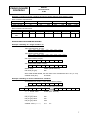
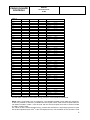
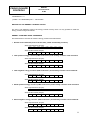
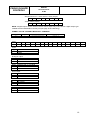
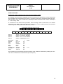
CARLO GAVAZZI
CONTROLS
WM3-96
Total pages: 36
Serial Protocol
V1 R3
WM3-96
(rev. B02 and following)
WM3-96 N2
(rev. C01 and following)
SERIAL COMMUNICATION PROTOCOL
Vers. 1 Rev. 3
July 7th, 2005
CARLO GAVAZZI
CONTROLS
WM3-96
Serial Protocol
V1 R3
Index
Index .........................................................................................................................................2
SERIAL COMMUNICATION PROTOCOL ....................................................................................3
INTRODUCTION.........................................................................................................................3
FUNCTIONS ...............................................................................................................................3
MEMORY AREA .........................................................................................................................5
RAM VARIABLES MAP ..............................................................................................................5
INSTANTANEOUS VARIABLES MAP .....................................................................................................5
VARIABLE FORMAT.........................................................................................................................6
INSTANTANEOUS VARIABLES READING ..............................................................................................7
ENERGY COUNTERS MAP.........................................................................................................8
READING OF THE ENERGY COUNTER VALUES ...................................................................... 10
WRITING OF THE ENERGY COUNTER VALUES ....................................................................... 11
ENERGY COUNTERS RESET COMMANDS .............................................................................. 11
ALARM STATUS MAP..................................................................................................................... 12
READING OF ALARM, DIAGNOSTIC AND REMOTE CONTROL OUTPUT STATUS ................................ 12
WRITE COMMAND FO R R EMOTE CONTROL OUTPUT.................................................................. 15
FORMAT OF THE “PRESENT MODULES” VA RIABLE................................................................... 16
HARMONIC ANALYSIS MA P ............................................................................................................. 18
R EADING OF THE HARMONIC DATA : EXAMPLES .................................................................................. 19
EEPROM VARIABLE MAP ....................................................................................................... 20
EVENT LOGGING..................................................................................................................... 23
MONTHLY ENERGY COUNTERS ................................................................................................2
EEPROM CONFIGURATION DATA FORMAT .............................................................................6
EXAMPLES: HOW TO READ THE DATA FROM EEPROM .......................................................... 10
READING AND RESETTING MAXIMUM AND MINUMUM............................................................................ 10
EVENTS READING ..................................................................................................................... 12
CRC CALCULATION ALGORITHM ........................................................................................... 14
HARDWARE SPECIFICATIONS ............................................................................................... 15
RS485 INTERFACE ...................................................................................................................... 15
RS232 INTERFACE ...................................................................................................................... 17
2
WM3-96
CARLO GAVAZZI
CONTROLS
Serial Protocol
V1 R3
SERIAL COMMUNICATION PROTOCOL
INTRODUCTION
WM3-96 can be equipped with a RS485 or RS232 serial interface. The serial communication
protocol, MODBUS-RTU, is the same on both interfaces. When using RS485, it is possible to
connect up to 255 instruments using MODBUS protocol. When using RS232 it is only possible to
connect a single instrument (multidrop feature is not available).
The time-out for the answer is fixed in 300 ms.
The command’s structure of the protocol allows the user to read and write from/in the µP RAM
memory, the EEPROM (measured data, stored data, real time clock), so that all the functions are
completely transparent.
The communication parameters are configurable when using the RS485 interface while are fixed
when using the RS232 one, in accordance with the following table:
Interface
RS232
RS485
Baud rate (bps)
Parity
Stop bit
9600
None
1
1200
None, even, odd
1
2400
None, even, odd
1
4800
None, even, odd
1
9600
None, even, odd
1
NOTE: please refer to the instruction manual for any detail on the instrument programming.
The communication can be started only by the HOST unit, which sends the request frame. Each
frame contains the following information:
• slave address: is a number from 1 to 255, which identifies the instrument connected to the
network. Address 0 (zero) is accepted (in write frames only) by all the instruments, which will
execute the relevant command but won’t send any answer frame.
NOTE: The request frame must always contain the address even if, when using RS232, it is not
considered (every legal value is accepted).
• command: it defines the command type (e.g. read function, write function etc.).
• data fields: these numbers define the operating parameters of the command (e.g. the address of
the word, the value of the word to be written, etc.).
• CRC word: it allows to detect transmission errors that may occur. CRC calculation is carried out
by the MASTER unit once it has defined address, command and data fields. When the frame is
received by the SLAVE, it is stored in a temporary buffer. The CRC is calculated and then
compared with the received one. If they correspond and the address is recognised by the SLAVE
unit, the command is executed and an answer frame is sent.
If the CRC is not correct, the frame is discarded and no answer is sent.
FUNCTIONS
WM3-96 accepts the following three commands:
• Read words (code 04)
• Write one word (code 06)
• Send a check frame (code 08)
Function 04 (read words)
Request frame
Address
1 byte
from 1 to 255
Function
1 byte
04h
Data address
2 byte
MSB
LSB
n° of words
2 byte
MSB
LSB
CRC
2 byte
MSB
LSB
3
WM3-96
CARLO GAVAZZI
CONTROLS
Serial Protocol
V1 R3
NOTE: - The maximum number of word is 120 (240 byte).
- The address 00 is not allowed (it generates no answer)
Answer frame
Address
1 byte
from 1 to 255
Function
1 byte
04h
n° byte (=2 x n° word)
1 byte
MSB
LSB
Values
n° byte (=2 x n° word)
…
CRC
2 byte
MSB
LSB
Function 06 (write one word)
Request frame
Address
1 byte
from 1 to 255
Function
1 byte
06h
Data address
2 byte
MSB
LSB
Value
2 byte
MSB
LSB
CRC
2 byte
MSB
LSB
Answer frame
Address
1 byte
from 1 to 255
Function
1 byte
06h
Data address
2 byte
MSB
LSB
Value
2 byte
MSB
LSB
CRC
2 byte
MSB
LSB
NOTE: the answer frame is an echo of the request frame, which confirm the execution of the
command.
The write function cannot be used to modify the contents of the energy counter memory area.
Function 08 (send a check frame)
Request frame
Address
1 byte
From 1 to 255
Function
1 byte
08h
Diagnostic code
2 byte
00h
00h
Answer frame
Address
1 byte
From 1 to 255
Function
1 byte
08h
Diagnostic code
2 byte
00h
00h
Value
2 byte
AAh
55h
CRC
2 byte
MSB
LSB
55h
CRC
2 byte
MSB
LSB
Value
2 byte
AAh
NOTE: the answer frame is an echo of the request frame, which confirm the execution of the
command.
IMPORTANT: if the address is 00 (zero) all the instruments connected to the network will execute
the command but won’t send an answer frame.
If the request frame contains an invalid function, the answer frame will be an “exception response”.
Exception response
Address
Function
1 byte
1 byte
From 1 to 255
88h
Diagnostic code
2 byte
00h
00h
Value
2 byte
AAh
55h
CRC
2 byte
MSB
LSB
4
WM3-96
CARLO GAVAZZI
CONTROLS
Serial Protocol
V1 R3
MEMORY AREA
WM3-96 manages four different memory areas addressed as follows:
Memory area
Internal RAM
Internal RAM
Data storage EEPROM
Real Time Clock
0000h
00E8h
2000h
4000h
Area
00E7h
1fffh
3fffh
5fffh
Byte reading order
MSB,LSB
LSB,MSB
MSB,LSB
LSB
The bytes which are included in the answer frame following a read request of a short or int variable
stored in the internal RAM from address 00E8h to address 1FFFh are sent in the following order:
LSB, …, …, MSB.
NOTE: in the following pages the following notation will be used:
1 int = 4 byte;
1 short = 2 byte;
1 word = 2 byte;
1 byte = 8 bit.
RAM VARIABLES MAP
INSTANTANEOUS VARIABLES MAP
Word
1
2
3
4
5
6
7
8
9
10
11
12
13
14
15
16
17
18
19
20
21
22
23
24
25
26
27
28
29
ADDRESS
000
004
008
00C
010
014
018
01C
020
024
028
02C
030
034
038
03C
040
044
048
04C
050
054
058
05C
060
064
068
06C
070
30
074
BYTE
4
4
4
4
4
4
4
4
4
4
4
4
4
4
4
4
4
4
4
4
4
4
4
4
4
4
4
4
4
4
VARIABLE
V L1-N
A L1
W L1
V L2-N
A L2
W L2
V L3-N
A L3
W L3
V L1
V L2
V L3
VA L1
var L1
PF L1
VA L2
var L2
PF L2
VA L3
var L3
PF L3
V ∑
A n
W ∑
VA ∑
var ∑
PF ∑
THD V1
THDe V1
Type
V
A
P
V
A
P
V
A
P
V
V
V
P
P
C
P
P
C
P
P
C
V
A
P
P
P
C
D
D
THDo V1
D
Word
31
32
33
34
35
36
37
38
39
40
41
42
43
44
45
46
47
48
49
50
51
52
53
54
55
56
57
58
59
ADDRESS
BYTE
078
4
07C
4
080
4
084
4
088
4
08C
4
090
4
094
4
098
4
09C
4
0A0
4
0A4
4
0A8
4
0AC
4
0B0
4
0B4
4
0B8
4
0BC
4
0C0
4
0C4
4
0C8
4
0CC
4
0D0
4
4
4
4
4
4
0E8 1+1+
1+1
VARIABLE
THD V2
THDe V2
THDo V2
THD V3
THDe V3
THDo V3
THD A1
THDe A1
THDo A1
THD A2
THDe A2
THDo A2
THD A3
THDe A3
THDo A3
A dmd
VA dmd
TPF avg
W dmd
Hz
ASY
VL-N ∑
UN
D
D
D
D
D
D
D
D
D
D
D
D
D
D
D
A
P
C
P
H
D
V
V
Type
Unit V,A/P
inf1/2
5
WM3-96
CARLO GAVAZZI
CONTROLS
Serial Protocol
V1 R3
NOTE: all the variables in this table are contiguous. It is possible to read the whole area with a
single command sending, in the request frame, 000h as data address and 0076h as number of
words (that is 118 in decimal).
The values of the instantaneous variables are stored in the addresses from 000h to 0E7h. The data
are sent in 4-byte groups in the following order: MSB, ..., ..., LSB.
VARIABLE FORMAT
The value of all the instantaneous variables is stored as a 4 byte (2 word) int eger value. The decimal
point and the multiplier have to be set according to the inf1/2 word coding (see the following table)
for voltage (V), current (A) and power (P), in the position “111.1” for the variables of type THD (%)
and H (Hz) and in position “1.111” for the variables of type C (PF). The variables “PF L1”, “PF L2”,
PF L3”, “PF ∑“ are stored with a positive value if the power factor is “L” (inductive), and with a
negative value if the power factor is “C” (capacitive).
Variable format info map
Address
0E8
0E9
0EA
Byte
1
1
1
Variable
Info voltage value
Info current value
Info power value
Type
inf1
inf1
inf2
Decimal point and multiplier coding
INF value
d.p
0
1.111m
1
11.11m
2
111.1m
3
1.111
4
11.11
5
111.1
6
1111
7
11.11K
INF value
d.p
8
111.1k
9
1111k
10
11.11M
11
111.1M
12
1111M
13
11.11G
14
111.1G
15
NOTE: if a power value exceeds 9999, the autoranging function will intervene and modify the inf2
value. If the power value is lower than 99999 the inf2 will be increased of 1 unit, if the power value is
greater than 99999 but lower than 999999 the inf2 will be increased of 2 units and so on.
Example 1: reading of an int variable stored at address 100h
An int variable is 4 byte (2 word) long, so a 2-word read request must be sent:
Read command request frame
Address
Function
1 byte
1 byte
from 1 to 255
04
Read command answer frame
Address
Function n° byte
1 byte
1 byte
1 byte
from 1 to 255
04
04
Word address
2 byte
01h
00h
n° of words
2 byte
00h
02h
Value of int type variable
1° byte 2° byte 3° byte
4° byte
LSB
MSB
CRC
2 byte
MSB
LSB
CRC
2 byte
MSB
LSB
NOTE: Char variables
Char type variable (1 byte) must always be read carrying out a 1 word (2 bytes) read request and
taking only the needed byte into account. Note that the first byte which is sent is the byte relevant to
the specified word address. The following bytes are relevant to the previous address+1.
6
CARLO GAVAZZI
CONTROLS
WM3-96
Serial Protocol
V1 R3
Example 2: reading of 4 char variables (4 bytes=2 words) starting from address 1C0h
Read command request frame
Address
Function
1 byte
1 byte
from 1 to 255
04
Read command answer frame
Address
Function n° byte
1 byte
1 byte
1 byte
From 1 to
04
04
255
Word address
2 byte
01h
C0h
Value
1° byte
01C0h
n° of words
2 byte
00h
02h
Value
2° byte
01C1h
Value
3° byte
01C2h
Value request frame (8 byte):
01h 04h 00h 08h
00h
02h
CRC
CRC
Value answer frame (9 byte):
01h 04h 04h 00h
00h
63h
8Dh
CRC
Info request frame (8 byte):
01h 04h 00h E8h
00h
02h
CRC
CRC
Info answer frame (frame 9 byte):
01h 04h 04h 07h 07h
06h
00h
CRC
CRC
2 byte
MSB
LSB
Value
4° byte
01C3h
CRC
2 byte
MSB LSB
INSTANTANEOUS VARIABLES READING
Example 3: Reading of a single variable: W1
Stored value:
Info value (P type):
CRC
CRC
638Dh (25485 decimal)
06h
Since 9999<25485<99999, the inf2 value to be considered is 06+1=07 (11.11K)
Variable value (W1):
25.48 kW
Example 4: Reading of all the instantaneous variables:
All instantaneous values (+ info) request frame (8 byte):
01h 04h 00h 00h 00h 76h CRC CRC
01h
All instantaneous values (+ info) answer frame (241 byte):
04h ECh 00h 00h 01h 37h
07h 07h 0Ah
VL1-N stored value:
.....................
.....................
Info (V type) value:
Info (A type) value:
Info (P type) value:
0137h (0311 decimal)
Variable value (VL1-N):
3.11
03h
CRC
CRC
07h
07h
0Ah
kV
7
WM3-96
CARLO GAVAZZI
CONTROLS
Serial Protocol
V1 R3
ENERGY COUNTERS MAP
Table 1
ADDRESS
0EC
0F0
0F4
0F8
0FC
0FD
0FE
0FF
100
104
108
10C
110
114
118
11C
120
124
128
12C
130
134
138
13C
140
144
148
14C
150
154
158
15C
160
164
168
16C
170
174
178
17C
180
184
188
18C
190
194
198
19C
1A0
1A4
1A8
1AC
1B0
1B4
1B8
1BC
BYTE
4
4
4
4
1
1
1
1
4
4
4
4
4
4
4
4
4
4
4
4
4
4
4
4
4
4
4
4
4
4
4
4
4
4
4
4
4
4
4
4
4
4
4
4
4
4
4
4
4
4
4
4
4
4
4
4
SEASON
TOTALE
WINTER
PERIOD
1
2
3
4
SUMMER
1
2
3
4
HOLYDAY
1
2
3
4
COUNTER TYPE
KWh+
(LSB)
KWh(LSB)
KVARh+ (LSB)
KVARh- (LSB)
KWh+
(MSB)
KWh(MSB)
KVARh+ (MSB)
KVARh- (MSB)
KWh+
(LSB)
KWh(LSB)
KVARh+ (LSB)
KVARh- (LSB)
KWh+
(LSB)
KWh(LSB)
KVARh+ (LSB)
KVARh- (LSB)
KWh+
(LSB)
KWh(LSB)
KVARh+ (LSB)
KVARh- (LSB)
KWh+
(LSB)
KWh(LSB)
KVARh+ (LSB)
KVARh- (LSB)
KWh+
(LSB)
KWh(LSB)
KVARh+ (LSB)
KVARh- (LSB)
KWh+
(LSB)
KWh(LSB)
KVARh+ (LSB)
KVARh- (LSB)
KWh+
(LSB)
KWh(LSB)
KVARh+ (LSB)
KVARh- (LSB)
KWh+
(LSB)
KWh(LSB)
KVARh+ (LSB)
KVARh- (LSB)
KWh+
(LSB)
KWh(LSB)
KVARh+ (LSB)
KVARh- (LSB)
KWh+
(LSB)
KWh(LSB)
KVARh+ (LSB)
KVARh- (LSB)
KWh+
(LSB)
KWh(LSB)
KVARh+ (LSB)
KVARh- (LSB)
KWh+
(LSB)
KWh(LSB)
KVARh+ (LSB)
KVARh- (LSB)
8
WM3-96
CARLO GAVAZZI
CONTROLS
Serial Protocol
V1 R3
Table 2
ADDRESS
8EC
8ED
8EE
8EF
8F0
8F1
8F2
8F3
8F4
8F5
8F6
8F7
8F8
8F9
8FA
8FB
8FC
8FD
8FE
8FF
900
901
902
903
904
905
906
907
908
909
90A
90B
90C
90D
90E
90F
910
911
912
913
914
915
916
917
918
919
91A
91B
BYTE
1
1
1
1
1
1
1
1
1
1
1
1
1
1
1
1
1
1
1
1
1
1
1
1
1
1
1
1
1
1
1
1
1
1
1
1
1
1
1
1
1
1
1
1
1
1
1
1
SEASON
WINTER
PERIOD
1
2
3
4
SUMMER
1
2
3
4
HOLYDAY
1
2
3
4
COUNTER TYPE
KWh+
(MSB)
KWh(MSB)
KVARh+ (MSB)
KVARh- (MSB)
KWh+
(MSB)
KWh(MSB)
KVARh+ (MSB)
KVARh- (MSB)
KWh+
(MSB)
KWh(MSB)
KVARh+ (MSB)
KVARh- (MSB)
KWh+
(MSB)
KWh(MSB)
KVARh+ (MSB)
KVARh- (MSB)
KWh+
(MSB)
KWh(MSB)
KVARh+ (MSB)
KVARh- (MSB)
KWh+
(MSB)
KWh(MSB)
KVARh+ (MSB)
KVARh- (MSB)
KWh+
(MSB)
KWh(MSB)
KVARh+ (MSB)
KVARh- (MSB)
KWh+
(MSB)
KWh(MSB)
KVARh+ (MSB)
KVARh- (MSB)
KWh+
(MSB)
KWh(MSB)
KVARh+ (MSB)
KVARh- (MSB)
KWh+
(MSB)
KWh(MSB)
KVARh+ (MSB)
KVARh- (MSB)
KWh+
(MSB)
KWh(MSB)
KVARh+ (MSB)
KVARh- (MSB)
KWh+
(MSB)
KWh(MSB)
KVARh+ (MSB)
KVARh- (MSB)
A further table, relevant to the monthly energy counters, will be explained afterwards.
NOTE: Table 1 and Table 2 are not contiguous. The variables included in each table are contiguous,
so that it is possible to read every variables with two request frames. With the first request frame the
106 words included in Table 1 could be read, with the second request frame the 24 words included
in Table 2 could be read.
The values of all the total and partial energy counters are stored as a 5-byte integer (the first 4 bytes
th
are the less significant part, the 5 is the most significant one). The resolution of the counters is 10W
9
CARLO GAVAZZI
CONTROLS
WM3-96
Serial Protocol
V1 R3
(the decimal point position has to be set to “1.11Kwh (Kvarh)”).
th
Whereas the total counters MSB (5 byte) is contiguous to the less significant bytes, the partial
th
counters MSB (5 byte) is stored in a different area of the memory. For this reason it is required to
carry out two different read commands in order to get all the energy counter information.
READING OF THE ENERGY COUNTER VALUES
8-bytes request frame (read command, 10 word):
CRC CRC
01h 04h 00h ECh 00h 0Ah
25-bytes answer frame (read command):
1
2
3
4
ECh EDh EEh EFh
01h 04h 14h 00h 00h 00h 00h
11
F6h
00h
12
13
F7h F8h
00h BEh
14
F9h
FEh
5
F0h
94h
6
F1h
59h
15
16
17
18
19
FAh FBh FCh FDh Feh
FFh FFh 00h 00h 00h
7
8
F2h F3h
FFh FFh
9
F4h
94h
20
FFh
00h
CRC
CRC
10
F5h
02h
Starting from address ECh, it is possible to read all the energy counters by means of a single read
command (10 word, see the example above).
Reconstruction of the kWh+ total counter
The first 4 data bytes (less significant bytes) have to be placed side by side in the opposite order:
4
Efh
00h
3
EEh
00h
2
EDh
00h
1
ECh
00h
00000000h=0
The obtained 32-bit value has to be interpreted as a two’s complement value.
The relevant kWh+ MSB (byte n° 17), which has to be interpreted as a two’s complement value too,
must be multiplied by 1000000000 (decimal value). The result has to be algebraically added to the
previous value.
17
FCh
00h
1000000000*0=0
Finally the last result has to be divided by 100.
0+0/100=0 kWh
Example 5: reconstruction of the kWh- total counter
5
F0h
94h
6
F1h
59h
7
F2h
FFh
8
F3h
FFh
FF FF 59 94h = -42604
18
FDh
00h
10
CARLO GAVAZZI
CONTROLS
WM3-96
Serial Protocol
V1 R3
1000000000*0 = 0
(- 42604 + 0*1000000000)/100 = - 426.04 kWh
WRITING OF THE ENERGY COUNTER VALUES
The user is not allowed to write in the energy counter memory area. It is only possible to reset the
energy counter using fixed frames.
ENERGY COUNTERS RESET COMMANDS
The fixed frames to be used to reset the energy counters are listed below:
1. General reset command (reset of all the total, partial and monthly counters)
Reset request frame (8 byte):
01h 06h 00h ECh
D4h
F0h
CRC
CRC
Reset answer frame (8 byte):
01h 06h 00h ECh
D4h
F0h
CRC
CRC
2. Total positive energy counters (kWh+ and kvarh+) and monthly counters reset command
Reset request frame (8 byte):
01h 06h 01h 00h
A5h
F0h
CRC
CRC
Reset answer frame (8 byte):
01h 06h 01h 00h
A5h
F0h
CRC
CRC
3. Total negative energy counters (kWh- and kvarh-) and monthly counters reset command
Reset request frame (8 byte):
01h 06h 01h 04h
23h
44h
CRC
CRC
Reset answer frame (8 byte):
01h 06h 01h 04h
23h
44h
CRC
CRC
4. Partial positive energy counters (kWh+ and kvarh+) and monthly counters reset command
Reset request frame (8 byte):
01h 06h 01h 08h
87h
35h
CRC
CRC
Reset answer frame (8 byte):
01h 06h 01h 08h
87h
35h
CRC
CRC
5. Partial negative energy counters (kWh- and kvarh-) and monthly counters reset command
Reset request frame (8 byte):
01h 06h 01h C0h
59h
12h
CRC
CRC
Reset answer frame (8 byte):
01h 06h 01h C0h
59h
12h
CRC
CRC
11
CARLO GAVAZZI
CONTROLS
WM3-96
Serial Protocol
V1 R3
ALARM STATUS MAP
Table 3
ADDRESS
1C0
1C2
1C4
1C6
1C8
1CA
1CC
1CE
1D0
1D2
1D4
1D6
1D8
1DA
1DC
1DE
1E0
1E2
1E4
1E6
1E8
1EA
1EC
1EE
1F0
1F2
1F4
1F6
BYTE
1+1
1+1
1+1
1+1
2
2
2
2
2
2
2
2
2
2
2
2
2
2
2
2
2
2
2
2
2
2
2
2
Variable type
Diagn0 , diagn1
Diagn2 , diagn3
Alarm0 , alarm1
Alarm2 , alarm3
control 0 type
control 1 type
control 2 type
control 3 type
status Relay 0
status Relay 1
status Relay 2
status Relay 3
Variable associated to
Variable associated to
Variable associated to
Variable associated to
ON set-point 0
ON set-point 1
ON set-point 2
ON set-point 3
OFF set-point 0
OFF set-point 1
OFF set-point 2
OFF set-point 3
delay 0
delay 1
delay 2
delay 3
alarm
alarm
alarm
alarm
0
1
2
3
Table 4
ADDRESS
8DC
8DE
BYTE
1+1
1+1
Variable type
Remote 1, Remote 2
Remote 3, Remote 4
NOTE: the variables included in each of the previous tables are contiguous, so it is possible to read
every variables with two request frames. With the first request frame the 28 words included in Table
3 can be read, with the second request frame the 2 words included in Table 4 can be read.
In order to know the current digital output settings, see the EEPROM map paragraph.
READING OF ALARM, DIAGNOSTIC AND REMOTE CONTROL OUTPUT STATUS
th
The n digital output can work as pulse output, alarm output, diagnostic output or remote control
output.
th
th
In order to know if the n digital output is set as alarm, the n alarm byte (“alarm n”) must be read. If
the byte is equal to 0 it means that the digital output is not set as alarm, if it is equal to 1 the alarm
status is OFF, if it is equal to 2 the alarm status is ON.
The same considerations are valid in case of diagnostic output (“diagn n” byte must be read) or
remote control output (“Remote n” byte must be read).
Of course, only one among “alarm n”, “diagn n” and “remote n” byte can be different from 0. If all
th
these three bytes are equal to 0, it means that the n digital output is set as pulse output.
12
WM3-96
CARLO GAVAZZI
CONTROLS
Serial Protocol
V1 R3
The values stored in addresses from 1C8h to 1CEh explain the control type, coded as follows:
0 = UP
1 = UP-LATCH
2 = DOWN
3 = DOWN LATCH
The values stored in addresses from 1D0h to 1D6h explain if the relay is normally energised or deenergized:
0 = Normally de-energized
1 = Normally energized
In the addresses from 1D8h to 1DEh the variables associated to the alarms are stored, according to
the “Variable type coding” table (see page 28).
Example: if a control on variable W1 has been associated to alarm1, in the address 1DAh the value
12 must be stored
The Set-point ON and OFF values are stored as unsigned short.
The delay values are stored as short and must be included in the range from 0 to 255 seconds.
Example 6: “Diagnostic” read command
2-word read command request frame (8 byte):
01h 04h 01h C0h 00h 02h CRC CRC
01h
Digital output
Digital output
Digital output
Digital output
0:
1:
2:
3:
Read command answer frame (9 byte):
04h 04h 00h 00h 01h 00h CRC
CRC
NO Diagnostic
NO Diagnostic
Diagnostic OFF
NO Diagnostic
Example 7: “Alarm” read command
2-word read command request frame (8 byte):
01h 04h 01h C4h 00h 02h CRC CRC
01h
Digital output
Digital output
Digital output
Digital output
0:
1:
2:
3:
Read command answer frame (9 byte):
04h 04h 00h 01h 00h 00h CRC
CRC
NO Alarm
Alarm OFF
NO Alarm
NO Alarm
13
WM3-96
CARLO GAVAZZI
CONTROLS
Serial Protocol
V1 R3
Example 8: “Control type” read command
4-word read command request frame (8 byte):
01h 04h 01h C8h 00h 04h CRC CRC
01h
Digital
Digital
Digital
Digital
output
output
output
output
04h
0:
1:
2:
3:
08h
Read command answer frame (13 byte):
LSB MSB LSB MSB LSB MSB LSB
00h 00h 00h 00h 00h 00h 00h
MSB
00h
CRC
CRC
Not used (digital output 0 is not set as alarm, see previous example)
UP control
Not used
Not used
Example 9: “Relay status” read command
4-word read command request frame (8 byte):
01h 04h 01h D0h 00h 04h CRC CRC
01h
Digital
Digital
Digital
Digital
output
output
output
output
04h
0:
1:
2:
3:
08h
Read command answer frame (13 byte):
00h 00h 01h 00h 00h 00h 00h
00h
CRC
CRC
Not used (digital output 0 is not set as alarm, see example 7)
Normally energized
Not used
Not used
Example 10: “Variable associated to the alarm” read command
4-word read command request frame (8 byte):
01h 04h 01h D8h 00h 04h CRC CRC
01h
04h
Digital output 0:
Digital output 1:
Digital output 2:
Digital output 3:
08h
Read command answer frame (13 byte):
00h 00h 26h 00h 00h 00h 00h
00h
CRC
CRC
not used (digital output 0 is not set as alarm, see example 7)
THD A1
not used
not used
Example 11: “ON Set-point” (alarm activation) read command
4-word read command request frame (8 byte):
01h 04h 01h E0h 00h 04h CRC CRC
01h
Digital
Digital
Digital
Digital
output
output
output
output
0:
1:
2:
3:
04h
08h
Read command answer frame (13 byte):
00h 00h 64h 00h 00h 00h 00h
00h
CRC
CRC
not used (digital output 0 is not set as alarm, see example 7)
10.0% (0064h = 100 decimal)
not used
not used
14
WM3-96
CARLO GAVAZZI
CONTROLS
Serial Protocol
V1 R3
Example 12: “OFF Set-point” (alarm deactivation) read command
4-word read command request frame (8 byte):
01h 04h 01h E8h 00h 04h CRC CRC
01h
Digital
Digital
Digital
Digital
output
output
output
output
04h
0:
1:
2:
3:
08h
Read command answer frame (13 byte):
00h 00h 32h 00h 00h 00h 00h
00h
CRC
CRC
not used (digital output 0 is not set as alarm, see example 7)
5.0% (0032h = 50 decimal)
not used
not used
Example 13: “Alarm activation delay” read command
4-word read command request frame (8 byte):
01h 04h 01h F0h 00h 04h CRC CRC
01h
Digital
Digital
Digital
Digital
output
output
output
output
0:
1:
2:
3:
04h
08h
Read command answer frame (13 byte):
00h 00h 04h 00h 00h 00h 00h
00h
CRC
CRC
not used (digital output 0 is not set as alarm, see example 7)
4 seconds
not used
not used
Example 14: “Latch alarm” reset command
To reset a UP -LATCH or DOWN-LATCH alarm, the relevant alarm byte must be set to 1.
01h
Reset command request frame (8 byte):
06h 01h C4h 00h 01h CRC CRC
01h
Reset command answer frame (8 byte):
06h 01h C4h 00h 01h CRC CRC
To reset the alarm 1, the byte at address 01C5h must be set to 1. The byte at address 01C4h must
be set to 00h, since it is relevant to alarm 0.
WRITE COMMAND FOR REMOTE CONTROL OUTPUT
The remote control digital output memory area is described in Table 4 and consists in 4 bytes
starting from address 08DCh (Remote1=8DCh, Remote2=8DDh, and so on).
th
To switch ON the n remote control output, the value 02h must be written in the “Remote n” byte,
th
while to switch OFF the n remote control output, the value 01h must be written in the “Remote n”
byte. Note again that the write command always writes 1 word (2 bytes).
Request frame: R1 = ON and R2 = OFF (8 byte):
01h 06h 08h DCh 02h 01h CRC CRC
Answer frame (8 byte):
01h 06h 08h
DCh
02h
01h
CRC
CRC
15
WM3-96
CARLO GAVAZZI
CONTROLS
Serial Protocol
V1 R3
Request frame: R1 = OFF and R2 = OFF (8 byte):
01h 06h 08h DCh 01h 01h CRC CRC
Answer frame (8 byte):
01h 06h 08h
DCh
01h
01h
CRC
CRC
NOTE: a digital output can be used as remote control output only if the relevant “digital output type”
variable stored in EEPROM is correctly set (see page 20 and following).
FORMAT OF THE “PRESENT MODULES” VARIABLE
ADDRESS
800
BYTE
2
Code
bit15 bit14 bit13
In3
In2
Code
XXXXXXXXXXXXXXXX
bit12 bit11
In1
bit10
bit9
Bit8
S3
Variable type
Module
bit7
S4
bit6
S2
bit5
232
bit4 bit3
CLK 485
bit2
bit1
bit0
AG34 AG12 Ing_d
Inputs
Ing_d Input module
0
Not present
1
Present
Analogue output
AG12 Analogue (out 1, 2) module
0
Not present
1
Present
AG34 Analogue (out 3, 4) module
0
Not present
1
Present
Serial
485
0
1
output
RS485 module
Not present
Present
232
0
1
RS232 module
Not present
Present
CLK
0
1
RTC Clock
Not present
Present
16
WM3-96
CARLO GAVAZZI
CONTROLS
Digital
S3A
0
0
0
0
1
1
1
1
output code
S4A
S2A
0
0
0
1
1
0
1
1
0
0
0
1
1
0
1
1
Digital
In1
0
1
inputs code
Digital input 1
ON
OFF
In2
0
1
Digital input 2
ON
OFF
In3
0
1
Digital input 3
ON
OFF
Serial Protocol
V1 R3
Available digital outputs on the inserted modules
1,2,3,4
1,2,3,4
1,2,3,4
1,2
3,4
3,4
1,2,3,4
None
Example 15: reading of the “present modules” variable
01h
1-word read request frame (8 byte)
04h 08h 00h 00h 01h CRC
01h
1-word read answer frmae (8 byte):
04h 02h 5Bh 61h CRC CRC
CRC
Module variable value: 615Bh = 0110000101011011
Available modules: input module, digital inputs, analogue output AG12, RS485, clock, digital output
3,4,
Digital inputs: ln3=OFF (open contact), ln2=OFF, ln1=ON (close contact)
17
WM3-96
CARLO GAVAZZI
CONTROLS
Serial Protocol
V1 R3
HARMONIC ANALYSIS MAP
Voltages1 (%)
ORDER/
VARIAB.
THD
Relative angles2 (°)
Currents (%)
1°
L1-N
ADD.
220
234
L2-N
ADD.
222
236
L3-N
ADD.
224
238
L1
ADD.
226
23A
L2
ADD.
228
23C
L3
ADD.
22A
23E
L1
ADD.
L2
ADD.
L3
ADD.
240
242
244
2°
248
24A
24C
24E
250
252
254
256
258
3°
25C
25E
260
262
264
266
268
26A
26C
4°
270
272
274
276
278
27A
27C
27E
280
5°
284
286
288
28A
28C
28E
290
292
294
6°
298
29A
29C
29E
2A0
2A2
2A4
2A6
2A8
7°
8°
9°
10°
11°
12°
13°
14°
15°
16°
17°
18°
19°
20°
21°
22°
23°
24°
25°
26°
27°
28°
29°
30°
31°
32°
33°
34°
35°
36°
37°
38°
39°
40°
41°
42°
43°
44°
45°
46°
47°
48°
49°
50°
2AC
2AE
2B0
2B2
2B4
2B6
2B8
2BA
2BC
2C0
2C2
2C4
2C6
2C8
2CA
2CC
2CE
2D0
2D4
2D6
2D8
2DA
2DC
2DE
2E0
2E2
2E4
2E8
2EA
2EC
2EE
2F0
2F2
2F4
2F6
2F8
2FC
2FE
300
302
304
306
308
30A
30C
310
312
314
316
318
31A
31C
31E
320
324
326
328
32A
32C
32E
330
332
334
338
33A
33C
33E
340
342
344
346
348
34C
34E
350
352
354
356
358
35A
35C
360
362
364
366
368
36A
36C
36E
370
374
376
378
37A
37C
37E
380
382
384
388
38A
38C
38E
390
392
394
396
398
39C
39E
3A0
3A2
3A4
3A6
3A8
3AA
3AC
3B0
3B2
3B4
3B6
3B8
3BA
3BC
3BE
3C0
3C4
3C6
3C8
3CA
3CC
3CE
3D0
3D2
3D4
3D8
3DA
3DC
3DE
3E0
3E2
3E4
3E6
3E8
3EC
3EE
3F0
3F2
3F4
3F6
3F8
3FA
3FC
400
402
404
406
408
40A
40C
40E
410
414
416
418
41A
41C
41E
420
422
424
428
42A
42C
42E
430
432
434
436
438
43C
43E
440
442
444
446
448
44A
44C
450
452
454
456
458
45A
45C
45E
460
464
466
468
46A
46C
46E
470
472
474
478
47A
47C
47E
480
482
484
486
488
48C
48E
490
492
494
496
498
49A
49C
4A0
4A2
4A4
4A6
4A8
4AA
4AC
4AE
4B0
4B4
4B6
4B8
4BA
4BC
4BE
4C0
4C2
4C4
4C8
4CA
4CC
4CE
4D0
4D2
4D4
4D6
4D8
4DC
4DE
4E0
4E2
4E4
4E6
4E8
4EA
4EC
4F0
4F2
4F4
4F6
4F8
4FA
4FC
4FE
500
504
506
508
50A
50C
50E
510
512
514
518
51A
51C
51E
520
522
524
526
528
52C
52E
530
532
534
536
538
53A
53C
540
542
544
546
548
54A
54C
54E
550
554
556
558
55A
55C
55E
560
562
564
568
56A
56C
56E
570
572
574
576
578
57C
57E
580
582
584
586
588
58A
58C
590
592
594
596
598
59A
59C
59E
5A0
5A4
5A6
5A8
5AA
5AC
5AE
5B0
5B2
5B4
5B8
5BA
5BC
5BE
5C0
5C2
5C4
5C6
5C8
5CC
5CE
5D0
5D2
5D4
5D6
5D8
5DA
5DC
5E0
5E2
5E4
5E6
5E8
5EA
5EC
5EE
5F0
5F4
5F6
5F8
5FA
5FC
5FE
600
602
604
608
60A
60C
60E
610
612
614
616
618
THDo
THDe
61C
630
61E
632
620
634
622
636
624
638
626
63A
18
WM3-96
CARLO GAVAZZI
CONTROLS
Serial Protocol
V1 R3
NOTE:
1
According to the selected electrical system, the voltages can be Phase to Phase Voltage or Phase
to Neutral Voltages.
2
Negligible values when the selected system is without neutral.
All the variables of the previous table are contiguous. Since the read command can read at most
120 words, it is possible to read all the harmonic analysis values with at least four request frames.
The values of the harmonic and distortion variables are represented as short (2 byte long). The
decimal point must be set to “111.1” for distortion and angle variables (THD, THDo, THDe), and to
“111.11” for the harmonic variables (h).
The stored values have physical meaning only if the harmonic analysis of the relevant phase is
enabled (please refer to the user manual for FFT enable function).
READING OF THE HARMONIC DATA: EXAMPLES
rd
Example 16: reading of the VL1 3 order harmonic
01h
“Value” request frame (frame 8 byte):
04h 02h 5Ch 00h 01h CRC CRC
“Value” answer frame (frame 7 byte):
01h 04h 02h 13h 0Dh CRC CRC
Variable value:
Value format:
rd
VL1 3 order harmonic value
0D13h
111.11
33.47%
3347 (decimal)
(the display shows 33.4%)
rd
Example 17: reading of the phase 1 - 3
01h
order relative angle
“Value” read request frame (frame 8 byte):
04h 02h 68h 00h 01h CRC CRC
“Value” read answer frame (frame 7 byte):
01h 04h 02h EFh 06h CRC CRC
Variable value:
06EFh
Value format:
111.1
rd
Phase 1–3 order relative angle:177.5°
1775 (decimal)
(the display shows 177°)
19
WM3-96
CARLO GAVAZZI
CONTROLS
Serial Protocol
V1 R3
EEPROM VARIABLE MAP
NOTE: f.s. means full scale; b.s. means beginning of the scale
WM3-96 configuration map
ADD.
2000
2002
2004
2006
2008
200A
200C
200E
2010
2012
2014
2016
2018
201A
201C
201E
2020
2022
2024
2026
2028
202A
202C
202E
2030
2032
2034
2036
2038
203A
203C
203E
2040
2042
2044
2046
2048
204A
204C
204E
2050
2052
2054
2056
2058
205A
205C
205E
2060
2062
2064
2066
VARIABLE
Password
System
CT
VT
type avg
time avg
enable FFT
type digit
field 1 e 2
field 3 e 4
RS485: address
RS485: baud rate
RS485: parity
Reserved
filter range
filter coeff.
event selection
event selection
USA/EUROclockformat
Language
Pulse type selection
dig. out type
Pulses/KWh out1
Pulses/KWh out2
Pulses/KWh out3
Pulses/KWh out4
info dig. out 1
Delay out 1
set-point out 1
Hysteresis out 1
info dig. out 2
delay out 2
set-point out 2
Hysteresis out 2
info dig. out 3
delay out 3
set-point out 3
Hysteresis out 3
info dig. out 4
delay out 4
set-point out 4
Hysteresis out 4
MAX
500
4
60000
60000
1
30
MIN
0
0
1
1
0
1
DEFAULT
0
2
10
10
0
15
See EEPROM data format tables
1
0
0
See EEPROM data format tables
See EEPROM data format tables
255
3
2
1
0
0
1
3
0
1000
255
1
1
10
3
BIT CHECK
0101XXXX XXXXXXXX
0101XXXX XXXXXXXX
not present
not present
0101XXXX XXXXXXXX
0101XXXX XXXXXXXX
0100XXXX XXXXXXXX
0101XXXX XXXXXXXX
0101XXXX XXXXXXXX
0101XXXX XXXXXXXX
not present
not present
not present
not present
not present
XXXXXXXX XXXXXXXX
XXXXXXXX XXXXXXXX
See EEPROM data format tables
See EEPROM data format tables
See EEPROM data format tables
0101XXXX XXXXXXXX
0101XXXX XXXXXXXX
XXXXXXXX XXXXXXXX
See EEPROM data format tables
not present
01XXXXXX XXXXXXXX
01XXXXXX XXXXXXXX
01XXXXXX XXXXXXXX
01XXXXXX XXXXXXXX
not present
not present
01XXXXXX XXXXXXXX
01XXXXXX XXXXXXXX
not present
not present
01XXXXXX XXXXXXXX
01XXXXXX XXXXXXXX
not present
not present
01XXXXXX XXXXXXXX
01XXXXXX XXXXXXXX
not present
not present
01XXXXXX XXXXXXXX
01XXXXXX XXXXXXXX
1000
1000
1000
1000
1
1
1
1
1
1
1
1
See EEPROM data format tables
255
f.s
f.s
0
b.s.
0
0
0
0
See EEPROM data format tables
255
f.s
f.s
0
b.s.
0
0
0
0
See EEPROM data format tables
255
f.s
f.s
0
b.s.
0
0
0
0
See EEPROM data format tables
255
f.s
f.s
0
b.s.
0
0
0
0
20
WM3-96
CARLO GAVAZZI
CONTROLS
Serial Protocol
V1 R3
WM3-96 configuration map (continue)
ADD.
2080
2082
2084
2086
2088
208A
208C
208E
2090
2092
2094
2096
2098
209A
209C
209E
20A0
20A2
20A4
20A6
20A8
20AA
20AC
20AE
20B0
20B2
20B4
20B6
20B8
20BA
20BC
20BE
20C0
20C2
20C4
20C6
20C8
20CA
20CC
20CE
20D0
20D2
20D4
20D6
20D8
20DA
20DC
20DE
20E0
20E2
20E4
20E6
VARIABLE
MAX
info analog out 1 See EEPROM
min % an. out 1
1000
max % an. out 1
1000
min input out 1
f.s.
max input 1
f.s.
See EEPROM
info an. out 2
min % an. out 2
1000
max % an. out 2
1000
min input out 2
f.s.
max input out 2
f.s.
See EEPROM
info an. out 3
min % an. out 3
1000
max % an. out 3
1000
min input out 3
f.s.
max input out 3
f.s.
See EEPROM
info an. out 4
min % an. out 4
1000
max % an. out 4
1000
min input out 4
f.s.
max input out 4
f.s.
type
type
type
type
type
type
type
type
type
type
type
type
type
type
type
type
type
type
type
type
MAX1
MAX2
MAX3
MAX4
MAX5
MAX6
MAX7
MAX8
MAX9
MAX10
MAX11
MAX12
MIN1
MIN2
MIN3
MIN4
MIN5
MIN6
MIN7
MIN8
-----------------------------------------
MIN
DEFAULT
data format tables
0
0
b.s.
b.s.
0
1000
b.s.
f.s.
data format tables
0
0
b.s.
b.s.
0
1000
b.s.
f.s.
data format tables
0
0
b.s.
b.s.
0
1000
b.s.
f.s.
data format tables
0
0
b.s.
b.s.
-----------------------------------------
0
1000
b.s.
f.s.
not
not
not
not
not
not
not
not
not
not
not
not
not
not
not
not
not
not
not
not
BIT CHECK
present
present
present
present
present
present
present
present
present
present
present
present
present
present
present
present
present
present
present
present
0101XXXX
0101XXXX
0101XXXX
0101XXXX
0101XXXX
0101XXXX
0101XXXX
0101XXXX
0101XXXX
0101XXXX
0101XXXX
0101XXXX
0101XXXX
0101XXXX
0101XXXX
0101XXXX
0101XXXX
0101XXXX
0101XXXX
0101XXXX
XXXXXXXX
XXXXXXXX
XXXXXXXX
XXXXXXXX
XXXXXXXX
XXXXXXXX
XXXXXXXX
XXXXXXXX
XXXXXXXX
XXXXXXXX
XXXXXXXX
XXXXXXXX
XXXXXXXX
XXXXXXXX
XXXXXXXX
XXXXXXXX
XXXXXXXX
XXXXXXXX
XXXXXXXX
XXXXXXXX
21
WM3-96
CARLO GAVAZZI
CONTROLS
Serial Protocol
V1 R3
WM3-96 configuration map (continue)
ADD.
2100
2101
2102
2103
2104
2105
2106
2107
2108
2109
210A
210B
210C
210D
210E
210F
2110
2111
2112
2113
2114
2115
2116
2117
2118
2119
211A
211B
211C
211D
211E
211F
2120
2121
2122
2123
2124
2125
2126
2127
2128
2129
212A
212B
212C
212D
212E
212F
val
val
val
val
val
val
val
val
val
val
val
val
val
val
val
val
val
val
val
val
val
val
val
val
VARIABLE
MAX1(msb)
MAX1(lsb)
MAX2(msb)
MAX2(lsb)
MAX3(msb)
MAX3(lsb)
MAX4(msb)
MAX4(lsb)
MAX5(msb)
MAX5(lsb)
MAX6(msb)
MAX6(lsb)
MAX7(msb)
MAX7(lsb)
MAX8(msb)
MAX8(lsb)
MAX9(msb)
MAX9(lsb)
MAX10(msb)
MAX10(lsb)
MAX11(msb)
MAX11(lsb)
MAX12(msb)
MAX12(lsb)
val
val
val
val
val
val
val
val
val
val
val
val
val
val
val
val
MIN1(msb)
MIN1(lsb)
MIN2(msb)
MIN2(lsb)
MIN3(msb)
MIN3(lsb)
MIN4(msb)
MIN4(lsb)
MIN5(msb)
MIN5(lsb)
MIN6(msb)
MIN6(lsb)
MIN7(msb)
MIN7(lsb)
MIN8(msb)
MIN8(lsb)
MAX
MIN
DEFAULT
BIT CHECK
22
WM3-96
CARLO GAVAZZI
CONTROLS
Serial Protocol
V1 R3
EVENT LOGGING
Event logging map
2300
2308
2310
2318
2320
2328
4
4
4
4
4
4
…
…
31F8
4 words Event 480
th
N
words
words
words
words
words
words
Event
Event
Event
Event
Event
Event
The stored information relevant to every event
are the following: event type, hour, minutes,
seconds, day, month, year, value.
All these data are included in the relevant 4
words, coded as follow.
1
2
3
4
5
6
To reset the events, it is necessary to write 0
in every of the sideways listed addresses and
to reset the event counter, placed at the
address 80Ch.
…
event coding
Word1
hour
XXXXX
min
XXXXXX
event type
XXXXX
Word2
month
XXXX
day
XXXXX
year
XXXXXXX
Seconds
0101XXXXXX
Word3
variable type
XXXXXX
value
XXXXXXXXXXXXXXXX
Word3
Variable type coding
Refer to the relevant table in “EEPROM configuration data” chapter.
Event type coding:
MAX
MIN
DIAGNOSTIC 1
DIAGNOSTIC 2
DIAGNOSTIC 3
DIAGNOSTIC 4
DIAGNOSTIC 1
DIAGNOSTIC 2
DIAGNOSTIC 3
DIAGNOSTIC 4
REMOTE 1
REMOTE 2
REMOTE 3
ON
ON
ON
ON
OFF
OFF
OFF
OFF
ON
ON
ON
1
2
3
4
5
6
7
8
9
10
11
12
13
REMOTE 4
REMOTE 1
REMOTE 2
REMOTE 3
REMOTE 4
ALARM 1
ALARM 2
ALARM 3
ALARM 4
ALARM 1
ALARM 2
ALARM 3
ALARM 4
ON
OFF
OFF
OFF
OFF
ON
ON
ON
ON
OFF
OFF
OFF
OFF
14
15
16
17
18
19
20
21
22
23
24
25
26
23
CARLO GAVAZZI
CONTROLS
WM3-96
Serial Protocol
V1 R3
MONTHLY ENERGY COUNTERS
The reading of the values of the energy counters relevant to the previous three months is feasible by
reading the data stored in the three tables described below. The tables have the same structure:
they are composed of 14 32-bytes pages where the total and partial counter values are stored on
the first day of the month at 0.00.00. The storing order of the table is the following (assuming, for
example, to begin the WM3 use in January): January data = table A, February data = table B, March
data = table C, April data = table A (overwriting the January data), and so on.
Pages structure:
Page 1: the initial 16 bytes, grouped 4 by 4, are the four-total counter LSB part
(KWh+ ,KWh-, Kvarh+, Kvarh-)
Page 2: the initial 20 bytes, grouped 5 by 5, are the four-winter tariff 1 partial counters values
Page 3: the initial 20 bytes, grouped 5 by 5, are the four-winter tariff 2 partial counters values
Page 4: the initial 20 bytes, grouped 5 by 5, are the four-winter tariff 3 partial counters values
Page 5: the initial 20 bytes, grouped 5 by 5, are the four-winter tariff 4 partial counters values
Page 6: the initial 20 bytes, grouped 5 by 5, are the four-summer tariff 1 partial counters values
Page 7: the initial 20 bytes, grouped 5 by 5, are the four-summer tariff 2 partial counters values
Page 8: the initial 20 bytes, grouped 5 by 5, are the four-summer tariff 3 partial counters values
Page 9: the initial 20 bytes, grouped 5 by 5, are the four-summer tariff 4 partial counters values
Page 10: the initial 20 bytes, grouped 5 by 5, are the four-holiday tariff 1 partial counters values
Page 11: the initial 20 bytes, grouped 5 by 5, are the four-holiday tariff 2 partial counters values
Page 12: the initial 20 bytes, grouped 5 by 5, are the four-holiday tariff 3 partial counters values
Page 13: the initial 20 bytes, grouped 5 by 5, are the four-holiday tariff 4 partial counters values
Page 14: the initial 4 bytes are the four-total counter MSB part, then 10 not used bytes follow, then
the following two bytes are relevant respectively to the year and month when the table were stored.
How to reconstruct the energy counter values:
The energy values have to be reconstructed according to the procedure described at page 11. The
value of byte 5, multiplied by 1000000000, must be added to the byte1-byte2-byte3-byte4 value and
the sum divided by 100.
-
Total counters: byte5 is stored at page 14 of the relevant monthly table. byte1-byte2-byte3-byte4
are stored at page 1 (byte 1 has the lower address).
-
Partial counters: byte5 and byte1-byte2-byte3-byte4 are consecutively stored starting from the
address of the required counter (byte 5 has the lower address, then byte 1 is stored, etc.).
To obtain the energy consuption relevant to a given month, the tables relevant to the end and the
beginning of that month must be read, and the difference between the respective values must be
carried out.
2
WM3-96
CARLO GAVAZZI
CONTROLS
Serial Protocol
V1 R3
Monthly energy counters map
ADDRESS
3220 (page 1)
3224
3228
322C
3240 (page 2)
3244
3245
3249
324A
324E
324F
3253
3254
3260 (page 3)
3264
3265
3269
326A
326E
326F
3263
3264
BYTE
SEASON
4
TOTAL
4
4
4
4
4
4
4
4
WINTER
1
4
1
4
1
4
1
12
4
WINTER
1
4
1
4
1
4
1
12
PERIOD
COUNTER TYPE
Kwh+
(LSB)
Kwh(LSB)
KVARh+ (LSB)
KVARh- (LSB)
1
Kwh+
Kwh+
KVARh+
KVARh+
KwhKwhKVARhKVARh-
(LSB)
(MSB)
(LSB)
(MSB)
(LSB)
(MSB)
(LSB)
(MSB)
2
Kwh+
Kwh+
KVARh+
KVARh+
KwhKwhKVARhKVARh-
(LSB)
(MSB)
(LSB)
(MSB)
(LSB)
(MSB)
(LSB)
(MSB)
…
…
…
…
…
…
…
…
…
…
…
…
…
…
…
33A0 (page 13)
33A4
33A5
33A9
33AA
33AE
33AF
33B3
33B4
33C0 (page 14)
33C1
33C2
33C3
33C4
33CE
33CF
33D0
4
1
4
1
4
1
4
1
12
1
1
1
1
10
1
1
16
HOLIDAY
YEAR/MONTH
4
Kwh+
Kwh+
KVARh+
KVARh+
KwhKwhKVARhKVARh-
(LSB)
(MSB)
(LSB)
(MSB)
(LSB)
(MSB)
(LSB)
(MSB)
Kwh+
KwhKVARh+
KVARh-
(MSB)
(MSB)
(MSB)
(MSB)
YEAR
MONTH
Table A
3
WM3-96
CARLO GAVAZZI
CONTROLS
Serial Protocol
V1 R3
Monthly energy counters map
ADDRESS
33E0 (page 1)
33E4
33E8
33EC
3400 (page 2)
3404
3405
3409
340A
340E
340F
3413
3414
3420 (page 3)
3424
3425
3429
342A
342E
342F
3433
3434
BYTE
SEASON
4
TOTAL
4
4
4
4
4
4
4
4
WINTER
1
4
1
4
1
4
1
12
4
WINTER
1
4
1
4
1
4
1
12
PERIOD
COUNTER TYPE
Kwh+
(LSB)
Kwh(LSB)
KVARh+ (LSB)
KVARh- (LSB)
1
Kwh+
Kwh+
KVARh+
KVARh+
KwhKwhKVARhKVARh-
(LSB)
(MSB)
(LSB)
(MSB)
(LSB)
(MSB)
(LSB)
(MSB)
2
Kwh+
Kwh+
KVARh+
KVARh+
KwhKwhKVARhKVARh-
(LSB)
(MSB)
(LSB)
(MSB)
(LSB)
(MSB)
(LSB)
(MSB)
…
…
…
…
….
…
…
…
…
…
…
…
…
…
…
3540 (page 13)
3544
3545
3549
354A
354E
354F
3553
3554
3560 (page 14)
3561
3562
3563
3564
356E
356F
3570
4
1
4
1
4
1
4
1
12
1
1
1
1
10
1
1
16
HOLIDAY
YEAR/MONTH
4
Kwh+
Kwh+
KVARh+
KVARh+
KwhKwhKVARhKVARh-
(LSB)
(MSB)
(LSB)
(MSB)
(LSB)
(MSB)
(LSB)
(MSB)
Kwh+
KwhKVARh+
KVARh-
(MSB)
(MSB)
(MSB)
(MSB)
YEAR
MONTH
Table B
4
WM3-96
CARLO GAVAZZI
CONTROLS
Serial Protocol
V1 R3
Monthly energy counters map
ADDRESS
35A0 (page 1)
35A4
35A8
35AC
35C0 (page 2)
35C4
35C5
35C9
35CA
35CE
35CF
35C3
35C4
35E0 (page 3)
35E4
35E5
35E9
35EA
35EE
35EF
35E3
35E4
BYTE
SEASON
4
TOTALE
4
4
4
4
4
4
4
4
WINTER
1
4
1
4
1
4
1
12
4
WINTER
1
4
1
4
1
4
1
12
PERIOD
COUNTER TYPE
Kwh+
(LSB)
Kwh(LSB)
KVARh+ (LSB)
KVARh- (LSB)
1
Kwh+
Kwh+
KVARh+
KVARh+
KwhKwhKVARhKVARh-
(LSB)
(MSB)
(LSB)
(MSB)
(LSB)
(MSB)
(LSB)
(MSB)
2
Kwh+
Kwh+
KVARh+
KVARh+
KwhKwhKVARhKVARh-
(LSB)
(MSB)
(LSB)
(MSB)
(LSB)
(MSB)
(LSB)
(MSB)
…
…
…
…
…
…
…
…
…
…
…
…
…
…
…
3720 (page 13)
3724
3725
3729
372A
372E
372F
3733
3734
3740 (page 14)
3741
3742
3743
3744
374E
374F
3750
4
1
4
1
4
1
4
1
12
1
1
1
1
10
1
1
16
HOLIDAY
YEAR/MONTH
4
Kwh+
Kwh+
KVARh+
KVARh+
KwhKwhKVARhKVARh-
(LSB)
(MSB)
(LSB)
(MSB)
(LSB)
(MSB)
(LSB)
(MSB)
Kwh+
KwhKVARh+
KVARh-
(MSB)
(MSB)
(MSB)
(MSB)
YEAR
MONTH
Table C
5
WM3-96
CARLO GAVAZZI
CONTROLS
Serial Protocol
V1 R3
EEPROM CONFIGURATION DATA FORMAT
Variable type coding
VARIABLE
V L1-N
V L2-N
V L3-N
VL-N ∑
V L1
V L2
V L3
V ∑
A L1
A L2
A L3
A n
W L1
W L2
W L3
W ∑
var L1
var L2
var L3
VAR ∑
VA L1
VA L2
VA L3
VA ∑
PF L1
PF L2
CODE
0
1
2
3
4
5
6
7
8
9
10
11
12
13
14
15
16
17
18
19
20
21
22
23
24
25
VARIABLE
PF L3
PF ∑
Hz
THD V1
THDe V1
THDo V1
THD V2
THDe V2
THDo V2
THD V3
THDe V3
THDo V3
THD A1
THDe A1
THDo A1
THD A2
THDe A2
THDo A2
THD A3
THDe A3
THDo A3
A dmd
VA dmd
TPF avg
W dmd
ASY
CODE
26
27
28
29
30
31
32
33
34
35
36
37
38
39
40
41
42
43
44
45
46
47
48
49
50
51
System coding
system
010XXXXX
010XXXXX
010XXXXX
010XXXXX
010XXXXX
XXXXX000
XXXXX001
XXXXX010
XXXXX011
XXXXX100
selection
1-phase
3+N phases bal
3+N phases unbal
3 phases bal
3 phases unbal
Average type coding
Average type
XXXXXXXX XXXXXXX0
XXXXXXXX XXXXXXX1
0101XXXX XXXXXXXX
selection
avg fixed
avg float
bit check
6
WM3-96
CARLO GAVAZZI
CONTROLS
Serial Protocol
V1 R3
Info out (1,2,3,4) coding
info out
XXXXXXXX
XXXXXX00
XXXXXX00
XXXXXX00
XXXXXX00
XXXXX0XX
XXXXX1XX
XX000000
00XXXXXX
01XXXXXX
10XXXXXX
11XXXXXX
XXXXXXXX
XXXXXXXX
selection
variable type(from 000000 to 110011, default 110011)
control type «up» (default)
control type «up.l»
control type «do»
control type «do.l»
normally de-energized relay
normally energized relay
Field n coding
The field n (n = 0, 1, 2, 3) variables are the variables chosen by the user to be shown on page 0 of
the WM3 display.
Field (1 and 2) coding
Field
XXXXXXXX XX000000
XXXX0000 00XXXXXX
0101XXXX XXXXXXXX
selection
field 1 variable
field 2 variable
bit check
Field (3 and 4) coding
Field
XXXXXXXX XX000000
XXXX0000 00XXXXXX
0101XXXX XXXXXXXX
selection
field 3 variable
field 4 variable
bit check
MAX and MIN type coding
MAX and MIN type
XXXXXXXX XX000000
0101XXXX XXXXXXXX
selection
field 1 variable (from 000000 to 110011, see TABLE «A»)
bit check
Digit type coding
digit type
XXXXXXXX XXXXXXX0
XXXXXXXX XXXXXXX1
0101XXXX XXXXXXXX
Selection
4 digit visualization
3½ digit visualization
bit check
RS485 baud rate coding
RS485 baud rate
XXXXXXXX XXXXXX00
XXXXXXXX XXXXXX01
XXXXXXXX XXXXXX10
XXXXXXXX XXXXXX11
selection
1200b
2400b
4800b
9600b
7
WM3-96
CARLO GAVAZZI
CONTROLS
Serial Protocol
V1 R3
FFT enable coding
FFT enable
XXXXXXXX XXXXXX11
XXXXXXXX XXXXXX00
XXXXXXXX XXXX11XX
XXXXXXXX XXXX00XX
XXXXXXXX XX11XXXX
XXXXXXXX XX00XXXX
Selection
fft V1-I1
fft V1-I1
fft V2-I2
fft V2-I2
fft V3-I3
fft V3-I3
disable
enable
disable
enable
disable
enable
USA/EURO clock format
Clock format
XXXXXXXX XXXXXXX0
XXXXXXXX XXXXXXX1
0101XXXX XXXXXXXX
Selection
USA clock format
European clock format
bit check
Language
Language format
XXXXXXXX XXXXX000
XXXXXXXX XXXXX001
XXXXXXXX XXXXX010
XXXXXXXX XXXXX011
XXXXXXXX XXXXX100
0101XXXX XXXXXXXX
Selection
English
Italian
German
French
Spanish
bit check
Pulse type selection
Pulse type selection
XXXXXXXX XXXXX000
XXXXXXXX XXXXX001
XXXXXXXX XXXXX010
XXXXXXXX XXXXX011
XXXXXXXX XXXXX100
XXXXXXXX XX000XXX
XXXXXXXX XX001XXX
XXXXXXXX XX010XXX
XXXXXXXX XX011XXX
XXXXXXXX XX100XXX
XXXXXXX0 00XXXXXX
XXXXXXX0 01XXXXXX
XXXXXXX0 10XXXXXX
XXXXXXX0 11XXXXXX
XXXXXXX1 00XXXXXX
XXXX000X XXXXXXXX
XXXX001X XXXXXXXX
XXXX010X XXXXXXXX
XXXX011X XXXXXXXX
XXXX100X XXXXXXXX
Selection
Out 1 pulses
Out 1 pulses
Out 1 pulses
Out 1 pulses
Out 1 pulses
Out 2 pulses
Out 2 pulses
Out 2 pulses
Out 2 pulses
Out 2 pulses
Out 3 pulses
Out 3 pulses
Out 3 pulses
Out 3 pulses
Out 3 pulses
Out 4 pulses
Out 4 pulses
Out 4 pulses
Out 4 pulses
Out 4 pulses
related
related
related
related
related
related
related
related
related
related
related
related
related
related
related
related
related
related
related
related
to:
to:
to:
to:
to:
to:
to:
to:
to:
to:
to:
to:
to:
to:
to:
to:
to:
to:
to:
to:
total energy counter
period 1 energy counter
period 2 energy counter
period 3 energy counter
period 4 energy counter
total energy counter
period 1 energy counter
period 2 energy counter
period 3 energy counter
period 4 energy counter
total energy counter
period 1 energy counter
period 2 energy counter
period 3 energy counter
period 4 energy counter
total energy counter
period 1 energy counter
period 2 energy counter
period 3 energy counter
period 4 energy counter
Info ang (analogue output 1, 2, 3, 4) coding
info ang
XXXXXXXX XX000000
Selection
Ang X variable (from 000000 to 110011, see TABLE «A»)
8
WM3-96
CARLO GAVAZZI
CONTROLS
Serial Protocol
V1 R3
Digital output type coding
type dig out
XXXXXXXX XXXXXX00
XXXXXXXX XXXXXX01
XXXXXXXX XXXXXX10
XXXXXXXX XXXX00XX
XXXXXXXX XXXX01XX
XXXXXXXX XXXX10XX
XXXXXXXX XX00XXXX
XXXXXXXX XX01XXXX
XXXXXXXX XX10XXXX
XXXXXXXX 00XXXXXX
XXXXXXXX 01XXXXXX
XXXXXXXX 10XXXXXX
XXXXXX00 XXXXXXXX
XXXXXX01 XXXXXXXX
XXXXXX10 XXXXXXXX
XXXXXX11 XXXXXXXX
XXXX00XX XXXXXXXX
XXXX01XX XXXXXXXX
XXXX10XX XXXXXXXX
XXXX11XX XXXXXXXX
XX00XXXX XXXXXXXX
XX01XXXX XXXXXXXX
XX10XXXX XXXXXXXX
XX11XXXX XXXXXXXX
00XXXXXX XXXXXXXX
01XXXXXX XXXXXXXX
10XXXXXX XXXXXXXX
11XXXXXX XXXXXXXX
selection
dig out 1 pulse (default type out 1)
dig out 1 control
dig out 1 alarm
dig out 2 pulse (default type out 2)
dig out 2 control
dig out 2 alarm
dig out 3 pulse (default type out 3)
dig out 3 control
dig out 3 alarm
dig out 4 pulse (default type out 4)
dig out 4 control
dig out 4 alarm
pulse 1 Kwh+ (default) (see note 1)
pulse 1 Kwh- (see note 1)
pulse 1 KVARh+ (see note 1)
pulse 1 KVARh- (see note 1)
pulse 2 Kwh+ (default) (see note 1)
pulse 2 Kwh- (see note 1)
pulse 2 KVARh+ (see note 1)
pulse 2 KVARh- (see note 1)
pulse 3 Kwh+ (default) (see note 1)
pulse 3 Kwh- (see note 1)
pulse 3 KVARh+ (see note 1)
pulse 3 KVARh- (see note 1)
pulse 4 Kwh+ (default) (see note 1)
pulse 4 Kwh- (see note 1)
pulse 4 KVARh+ (see note 1)
pulse 4 KVARh- (see note 1)
NOTE 1: the multiplier type depends on the “info P” variable (refer to the instantaneous variables
map).
9
WM3-96
CARLO GAVAZZI
CONTROLS
Serial Protocol
V1 R3
EXAMPLES: HOW TO READ THE DATA FROM EEPROM
NOTE: EEPROM is structured in word (if not differently advised) which are sent in the order MSB,
LSB (contrary to what happens during the INTERNAL RAM reading).
The value of the variables stored in EEPROM are 4-byte integer except from the values of the power
which are stored in a different way. Refer to example 21 to know how to read the power values.
READING AND RESETTING MAXIMUM AND MINUMUM
th
Example 18: “12
MAXIMUM variable type” read command
4-word read command request frame (8 byte):
01h 04h 20h D6h 00h 01h CRC CRC
read command answer frame (7 byte):
01h 04h 02h 50h 0Ah CRC CRC
th
12 MAX-variable type address:
Stored variable value:
Variable type:
20D6h
0Ah = 10 (decimal)
A L3 (phase 3 current)
Example 19: “Current info” read command
01h
“Info A” read request frame (frame 8 byte):
04h 00h E8h 00h 01h
CRC CRC
“Info A” read answer frame (frame 7 byte):
01h 04h 02h 06h 04h
CRC CRC
Info V value:
Info A value:
06h
04h
decimal point position: 1111
decimal point position: 11.11
Example 20: value of the “12
01h
th
1-word read request command (8 byte):
04h 21h 16h 00h 01h CRC CRC
01h
th
MAXIMUM” read command
Address of 12 MAX value:
Stored value:
Taking into account the results
A L3 value:
read answer frame (7 byte):
04h 02h 03h 6Ch CRC
CRC
2116h
036Ch = 876 (decimal)
of the previous examples:
8.76 A
10
WM3-96
CARLO GAVAZZI
CONTROLS
Serial Protocol
V1 R3
Example 21: value of the “12
th
MAXIMUM” read command in case of “power type” variable
The structure of the value of the power stored in EEPROM is the following:
Word 1
2116h
MSB
…
01h
Word 2
2117h
LSB d.p.
1-word read request command (8 byte):
04h 21h 16h 00h 01h CRC CRC
01h
read answer frame (7 byte):
04h 02h 19h E8h CRC
1
CRC
Value
d.p.
9
Eh 8h
th
Address of 12 MAX value:
Stored value:
2116h
19E8h è value = 19Eh = 414 (decimal);
decimal point position code = 8h = 111.1 k
Considering that, for example, the variable code is 12 (W L1):
W L1 value:
4.14 kW
th
Example 22: “12 MAXIMUM” reset command
01h
01h
1-word write request command (8 byte):
06h 21h 16h 00h 00h CRC CRC
Write answer command (8 byte):
06h 21h 16h 00h 00h CRC
CRC
11
WM3-96
CARLO GAVAZZI
CONTROLS
Serial Protocol
V1 R3
EVENTS READING
Example 23: read command of the event stored at address 2240h
The reading of the information regarding an event is carried out by transferring 4 words starting from
the first address of the selected event location, according to the Event Logging Map table (page 24).
The description of the event is obtained by decoding the data contained in the 4 words, according to
th
“n event coding” table.
In accordance to the above listed procedure, before reading a MAX or MIN event, the variable
associated to the MAX or MIN must be known. Then the info of the variable (decimal point position)
must be acquired. Finally the stored value must be read.
4-word read command frame (8 byte):
01h 04h 22h 40h 00h 04h FAh
01h
04h
08h
65h
read command answer frame (13 byte):
7Bh C1h 61h 80h 5Bh 42h 00h
Word 1:
Word 2:
Word 3:
Word 4:
7BC1h = 01111 011110 00001
6180h = 0110 00011 0000000
5B42h = 0101 101101 000010
0036h = 0000000000110110
Event type
Minutes
Hour
Year
Day
Month
Variable type
Seconds
Value
0001
011110
01111
0000000
00011
0110
001000
101101
110110
1
30
15
00
03
06
08
45
54
36h
88h
DFh
MAX
A L1
The engineering unit and the decimal point position of the variable are obtained by reading the “info”
value in the instantaneous variables area (see example 2).
12
WM3-96
CARLO GAVAZZI
CONTROLS
Serial Protocol
V1 R3
RTC DATA READING
The reading of the information regarding the RTC is carried out by transferring 4 words starting from
address 4000h as described in the following example.
Example 24: RTC data read command
01
01h
Seconds:
Minutes:
Hour:
Day of the week
Day of the month:
Month:
Year:
04h
4-word read command frame (8 byte):
04h 40h 00h 00h 04h E4h
09h
read command answer frame (13 byte):
Sec. Min. Hour Week Month Month Year
day . day
08h 12h 08h 11h 01h
08h
0Ah
01h 00h
30h
6Bh
12h = 18
08h = 8
11h = 17
01h = 1 (Monday)
08h = 8
0Ah = 10
0001h= 1 (2001)
13
WM3-96
CARLO GAVAZZI
CONTROLS
Serial Protocol
V1 R3
CRC CALCULATION ALGORITHM
CRC is calculated according to the relevant flow diagram (see below). An explanatory example will
follow.
Example 25: calculation of CRC starting from frame 0207h
CRC Inizialization
Load first byte
Execute XOR with the first byte of the frame
Execute 1st right Shift
Carry = 1 , load polynomial
Execute XOR with the polynomial
Execute 2nd right Shift
Carry = 1 , load polynomial
Execute XOR with the polynomial
Execute 3rd right Shift
Execute 4th right Shift
Carry = 1 , load polynomial
Execute XOR with the polynomial
Execute 5th right Shift
Execute 6th right Shift
Carry = 1 , load polynomial
Execute XOR with the polynomial
Execute 7th right Shift
Execute 8th right Shift
Carry = 1 , load polynomial
Execute XOR with the polynomial
1111 1111 1111
0000
1111 1111 1111
0111 1111 1111
1010 0000 0000
1101 1111 1111
0110 1111 1111
1010 0000 0000
1100 1111 1111
0110 0111 1111
0011 0011 1111
1010 0000 0000
1001 0011 1111
0100 1001 1111
0010 0100 1111
1010 0000 0000
1000 0100 1111
0100 0010 0111
0010 0001 0011
1010 0000 0000
1000 0001 0011
1111
0010
1101
1110
0001
1111
1111
0001
1110
1111
1111
0001
1110
1111
1111
0001
1110
1111
1111
0001
1110
Hex FFFF = CRC
1
n=0
1
CRC right shift
0
1
no
carry over
yes
CRC xor POLY = CRC
n = n+1
0
1
no
n>7
yes
0
1
Load the second byte of the frame
0000 0111
Execute XOR with the second byte of the frame 1000 0001 0011 1001
Execute 1st right Shift
0100 0000 1001 1100 1
Carry = 1 , load polynomial
1010 0000 0000 0001
Execute XOR with the polynomial
1110 0000 1001 1101
Execute 2nd right Shift
0111 0000 0100 1110 1
Carry = 1 , load polynomial
1010 0000 0000 0001
Execute XOR with the polynomial
1101 0000 0100 1111
Execute 3rd right Shift
0110 1000 0010 0111 1
Carry = 1 , load polynomial
1010 0000 0000 0001
Execute XOR with the polynomial
1100 1000 0010 0110
Execute 4th right Shift
0110 0100 0001 0011 0
Execute 5° right Shift
0011 0010 0000 1001 1
Carry = 1 , load polynomial
1010 0000 0000 0001
Execute XOR with the polynomial
1001 0010 0000 1000
Execute 6th right Shift
0100 1001 0000 0100 0
Execute 7th right Shift
0010 0100 1000 0010 0
Execute 8th right Shift
0001 0010 0100 0001 0
CRC Result
CRC xor BYTE = CRC
next BYTE
no
end message
yes
End
POLY = crc calculation polynominal: A001h
0001 0010 0100 0001
12h
41h
NOTE: the byte 41h is sent first (even if it’s the LSB),
then byte 12h is sent.
14
CARLO GAVAZZI
CONTROLS
WM3-96
Serial Protocol
V1 R3
HARDWARE SPECIFICATIONS
RS485 INTERFACE
General technical specifications
Baud rate
1200, 2400, 4800, 9600bps
Data format
1 start / 8 data / 1 stop bit / no parity
1 start / 8 data / 1 stop bit / even parity
1 start / 8 data / 1 stop bit / odd parity
Address
1 to 255
Broadcast
Yes (address 0 with function 06)
Standard functions
04: Read function (max 108 words)
06: Write function (max 1 word)
Special functions
80: Read from Flash memory (data-logging)
Answer buffer
264+5 byte
Identification code
16 (10h)
Synchr. Time-out
3 chars
Physical interface
MAX1482
RX termination
Jumper between Rx+ and T terminals
Available connections
4-wire (RS422 half duplex interface)
2-wire (RS485 interface)
Note:
A.
B.
C.
D.
Note
A
B
C
D
With a single request maximum 132 words can be read from WM4.
See paragraph 1.4 WM4-96 identification code.
It is the time that must elapse without receiving any character before starting the analysis of
the received frame.
RS422 interface is managed with the same protocol of the RS485 one: in this way only the
half-duplex communication is allowed (TX and RX not simultaneous).
Timing characteristics for 4-wire communication
T response: max answering time
T response: typical answering time
T delay1: minimum time for a new query on the same address
T delay2: minimum time for a new query on a different address
T null: maximum interruption time on the request frame
msec
600ms
100ms
10ms
10ms
3 char
15
CARLO GAVAZZI
CONTROLS
WM3-96
Serial Protocol
V1 R3
Timing characteristics for 2-wire communication
T response: max answering time
T response: typical answering time
T delay1: minimum time for a new query on the same address
T delay2: minimum time for a new query on a different address
T null: maximum interruption time on the request frame
msec
600ms
100ms
10ms
10ms
3 char
APPLICATION NOTES
1.
2.
3.
4.
5.
6.
If the instrument does not answer within the “max answering time”, it is necessary to repeat the
query. If the instrument does not answer after 2 or 3 consecutive queries, it must be considered
as not connected, faulty or having a different address. The same consideration is valid in case of
CRC errors or incomplete frames.
By entering the programming mode (by pressing the “S” key) the communication is interrupted.
Any data received during the programming mode are ignored.
EEPROM read and write commands must be carried out to manage “static” variables. Use them
only during the instrument set-up and not during the normal measuring mode in order to avoid to
extend the answer time and to limit the writing in EEPROM (max 100.000).
To avoid reflections or couplings between the communication wires it is suggested to terminate
the last instrument of the network and of the host. If some problems persist, bias the host
transmission. It is advisable to terminate the network also in case of short point to point
connections.
If the connection is longer than 1200 m a signal amplifier has to be used.
To calculate the time required to scan all the instruments of a network, the following formulae
are to be used:
N ° bit
*8
Baud _ rate
N ° bit
Treply =
* N ° char
Baud _ rate
TS = T _ request + T _ response + T _ reply + T _ delay1
TA = TS * N °request
TM = (TS + Tdelay 2) * N °instrument s
Trequest =
N° bit
N° char
N° word
TS
Tdelay1
TA
TM
N° instruments
Tdelay2
10 (no parity), 11 (even or odd parity)
5 + number of Words*2 (function 04), 8 (function 06)
Number of words to be read in the same request
Reading execution time
Minimum time for a new query on the same address
Instrument data acquisition time
Total network scanning time
Number of instruments connected in the network
Minimum time for a new query on a different address
16
WM3-96
CARLO GAVAZZI
CONTROLS
Serial Protocol
V1 R3
RS232 INTERFACE
General technical specifications
Baud rate
2400, 4800, 9600, 38400 bps
Data format
1 start / 8 data / 1 stop bit / no parity
Address
Not managed
Note:
A.
A
Nevertheless in the address cell a value from 1 to 255 must be.
9-pole female RS232 connector
Pin 1
DCD
Pin 2
TX
Pin 3
RX
Pin 4
Pin 5
Not used
GND
Pin
Pin
Pin
Pin
Not used
Not used
Not used
RING
6
7
8
9
Note
Note
Used only for modem connection
To be connected to the RX terminal
of the PC COM
To be connected to the TX terminal
of the PC COM
To be connected to the GND terminal
of the PC COM
Used only for modem connection
Note: to connect WM4 with a PC use a serial cable with “pin to pin” connections.
Timing characteristics for RS232 communication
T response: max answering time
T response: typical answering time
T delay: minimum time for a new query
T null: maximum interruption time on the request frame
msec
600ms
100ms
10ms
50msec
Note: T null is independent of the selected baud-rate value
17
CARLO GAVAZZI
CONTROLS
WM3-96
Serial Protocol
V1 R3
APPLICATION NOTES
1.
2.
3.
4.
If the instrument does not answer within the “max answering time”, it is necessary to repeat the
query. If the instrument does not answer after 2 or 3 consecutive queries, it must be considered
as not connected, faulty or having a different address. The same consideration is valid in case of
CRC errors or incomplete frames.
By entering the programming mode (by pressing the “S” key) the communication is interrupted.
Any data received during the programming mode are ignored.
EEPROM read and write commands must be carried out to manage “static” variables. Use them
only during the instrument set-up and not during the normal measuring mode in order to avoid to
extend the answer time and to limit the writing in EEPROM (max 100.000).
Control lines are not managed.
18