1
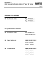
User manual
Ex Remote station
Ex Remote station
XGA 15" family
SXGA 18" family
Version 3.00
type 17-71KB-45../....
type 17-71KB-55../....
User manual
Remote station XGA
15'' family
Remote station SXGA
18'' family
Publisher and
copy rights:
BARTEC GmbH
Max-Eyth-Strasse 16
97980 Bad Mergentheim
Germany
Phone:
Fax:
+49 7931 597-0
+49 7931 597-183
(Switch Office)
All rights reseved. Reproductions and extracts from this document are not permitted without
written approval of the publisher. The manual was constructed with care. However, BARTEC
GmbH takes over no liability for possible mistakes in this manual and their consequences. As well
every liability is rejected by use of the product in a foreign way.
User manual
Ex Remote station 15'' and 18'' family
Version 3.00
Page 3
Inhaltsverzeichnis
1.
General ........................................................................................................................................................ 5
1.1
Components................................................................................................................................. 5
1.2
Overview - Product family ............................................................................................................ 6
1.3
General installation instructions ................................................................................................... 7
1.4
Assembly and disassembly.......................................................................................................... 8
1.5
Maintenance, modification and service ........................................................................................ 8
1.6
Commissioning ............................................................................................................................ 8
2.
Technical data........................................................................................................................................... 10
2.1
Specifications Remote station.................................................................................................... 10
2.1.1
Specification Remote station XGA 15'' family - Type 17-71KB-45../.. ........................................ 11
2.1.2
Specification Remote station SXGA 18'' family - Type 17-71KB-55../........................................ 11
2.2
Overview.................................................................................................................................... 11
2.3
Connections for operation.......................................................................................................... 12
2.3.1
Power supply ............................................................................................................................. 12
2.3.2
EEx i keyboard / mouse ............................................................................................................. 12
2.3.3
Data cable (video, keyboard and trackball) from local station .................................................... 13
3.
Overview of connection diagram ............................................................................................................ 14
3.1
Standard application point to point............................................................................................. 14
3.2
Special application cascade circuit ............................................................................................ 14
4.
Possible adjustments............................................................................................................................... 15
4.1
Adjustment of cable length......................................................................................................... 15
4.2
Fine tuning picture quality .......................................................................................................... 16
5.
Operation................................................................................................................................................... 17
5.1
Connection local unit.................................................................................................................. 17
5.2
Connect the Local station with Remote station .......................................................................... 17
5.3
Connection EEx i keyboard and remote station ......................................................................... 18
5.4
Installation touch screen (only for type 17-71KB-.53./....) .......................................................... 18
Appendix A
Operation for type 17-71KB-45../....
.................................................................................... 21
Appendix B
Operation for type 17-71KB-55../....
................................................................................... 25
Appendix C
Declaration of EC-Conformity................................................................................................. 39
EC-TYPE-EXAMINATION CERTIFICATE
BMS00755_Rev0_02-2005.doc y User manual Ex Remote station 15″ and 18″ family y Rev. 0 / Status: 3. March 2005 y Technical data subject to change
User manual
Ex Remote station 15'' and 18'' family
Version 3.00
Page 5
1.
General
1.1
Components
The Ex remote station is a monitor extension with a keyboard and a trackball (optionally with mouse connection).
Furthermore, the Ex remote station is optionally available with a touch-screen.
The device was especially developed for application in hazardous areas and is ATEX-certified:
■
Remote station XGA
Remote station SXGA
15'' family
18'' family
type 17-71KB-45../….
type 17-71KB-55../….
for Zone 1
■
Remote station XGA
Remote station SXGA
15'' family
18'' family
type 17-71KB-450./.005
type 17-71KB-550./.005
for Zone 21
The type of protection is Ex d – flameproof enclosure – with intrinsically safe circuits routed to the outside and Ex d cable
glands or Ex d cable entries.
For Zone 21, only the aluminium version in connection with the BMF 105 stainless steel keyboard with mouse!
The complete Ex Remote station consists of the following components:
Ex d Remote station
Type 17-71K1-35../....
PTB 00 ATEX 1003
enclosed 1st supplement
IBExU 02 ATEX 1163
Power limiting unit
Type 17-71K4-..01/....
KEMA 98 ATEX 1988 X
enclosed 1st supplement
enclosed 2nd supplement
enclosed 3rd supplement
PC input device
keyboard
Type 17-71K3-...1/….
KEMA 98 ATEX 2558 X
trackball
enclosed 1st supplement
mouse
enclosed 2nd supplement
enclosed 3rd supplement
enclosed 4th supplement
For special conditions also see the appropriate EC-type-examination certificate.
BMS00755_Rev0_02-2005.doc y User manual Ex Remote station 15″ and 18″ family y Rev. 0 / Status: 3. March 2005 y Technical data subject to change
User manual
Ex Remote station 15'' and 18'' family
Version 3.00
1.2
Page 6
Overview - Product family
Ex Remote station 15'' family
Ex Remote station 18'' family
Type 17-71KB-45../.0..
Standard version
Type 17-71KB-55../.0..
Standard version
Type 17-71KB-45../.005
DustEx version
Type 17-71KB-55../.005
DustEx version
Ex Remote station 15'' and 18'' family
Type 17-71KB-.53./.000
with touch screen
Ex Remote station 15'' and 18'' family
Type 17-71KB-.50./.3..
BMS00755_Rev0_02-2005.doc y User manual Ex Remote station 15″ and 18″ family y Rev. 0 / Status: 3. March 2005 y Technical data subject to change
Stainless steel version
User manual
Ex Remote station 15'' and 18'' family
Version 3.00
1.3
Page 7
General installation instructions
Please observe the following points for safe commissioning:
The user must mount and install the Ex d enclosures with their corresponding electronic components within the Ex area
prior to commissioning. The sealed Ex d enclosure may be installed directly within the Ex area. Altogether four sealed
openings are located on the back of the device. The sealed openings that are accessible to the user are arranged and
marked as follows.
Openings which are accessible for the user are set and marked as follows:
Ex d setup
Ex d power Ex d data
Ex i data
These openings have different functions and must be considered as separate units
1.
Ex d compartment X1 with terminals for supply voltage (Ex d supply) as well as Ex d compartment X2 with
terminals for data lines (Ex d data).
Within explosive atmospheres, these terminal compartments may be opened and used exclusively when
disconnected from the supply.
2.
Terminal compartment X3 with terminals for an Ex i input unit (Ex i data). Keyboard, type 17-71K3-...1/.... KEMA 98 ATEX 2558 X from BARTEC.
Within explosive atmospheres, this terminal compartment can also be worked on when voltage is applied.
3.
Opening for one-time settings on the device (Ex d settings).
The access may be opened only when the absence of any explosive atmosphere is guaranteed.
Prior to commissioning of the device (in the presence of explosive atmospheres) make sure that the
enclosure is completely sealed and all screws tightened.
BMS00755_Rev0_02-2005.doc y User manual Ex Remote station 15″ and 18″ family y Rev. 0 / Status: 3. March 2005 y Technical data subject to change
User manual
Ex Remote station 15'' and 18'' family
Version 3.00
1.4
Page 8
Assembly and disassembly
During installation ensure safe and secure mounting with easy accessibility on site.
■
Do not fail to disconnect from supply prior to the enclosure’s assembly and disassembly.
You need the following tools for assembly:
1.5
Ex d cable gland
open ring nut wrench DIN 3118, SW 27.
lid (back)
hexagon-socket wrench SW 3; DIN 911
Maintenance, modification and service
As the Ex Remote station is a very complex device, the manufacturer must carry out all maintenance and repair works, or
persons authorized by the manufacturer.
1.6
Commissioning
Commissioning of the Ex Remote station requires the use of the openings of the Ex d enclosure described under
„Commissioning“.
Both voltage supply and necessary data line must be connected to the terminals provided and marked for such purpose
(see the terminal description, chapter “Connections for operation”).
Afterwards make sure to safely close the terminal compartments and to tighten all the screws.
The external PE connection must be included in the equipotential bonding system on site.
Trained personnel must carry out these activities. The terminals are located within separate terminal compartments in order
to guarantee an easy installation of the connections. Furthermore, the user is kept from direct contact with the mounted
hardware components.
Separately certified Ex d cable glands or Ex d cable entries are used.
When closing the flameproof compartments make sure that the joint surfaces have been cleaned and that all screws set
equally tight.
The device may be commissioned only after complete assembly of the enclosure and in total absence of explosive
atmospheres.
BMS00755_Rev0_02-2005.doc y User manual Ex Remote station 15″ and 18″ family y Rev. 0 / Status: 3. March 2005 y Technical data subject to change
User manual
Ex Remote station 15'' and 18'' family
Version 3.00
Page 9
Connection cables:
The connection cables for the data and the Supply voltage must be installed according to EN 60079-14.
The terminal assignment of the individual compartments is described in the Operator panel manual.
Important information:
■
The user is only allowed to carry out the necessary wiring works on the terminals
accessible to him. Any further disassembly must be carried out by the manufacturer
or persons authorised by the manufacturer.
■
Ex d compartment X1 with terminals for supply voltage (Ex d supply) and
Ex d compartment X2 with terminals for data lines (Ex d data).
■
Within explosive atmospheres, these terminal compartments may be opened and
used exclusively when disconnected from the supply.
■
Compartment X3 with terminals for Ex i input unit (Ex i data). Keyboard
type 17-71K3-...1/.... KEMA 98 ATEX 2558 X from BARTEC.
■
Within explosive atmospheres, this terminal compartment can also be worked on
when voltage is applied.
■
Opening for one-time settings on the device (Ex d settings)
The access may be opened only when the absence of any explosive atmosphere is
guaranteed.
■
Prior to commissioning of the device (in the presence of explosive atmospheres)
make sure that the enclosure is completely sealed and all screws tightened.
■
Devices, which have sustained any damage to the glass front, must be shut down
immediately.
NPT threads are provided and marked for the Ex d line bushings or Ex d cable glands. Other, non-marked threads
are manufactured according to the ISO standards.
BMS00755_Rev0_02-2005.doc y User manual Ex Remote station 15″ and 18″ family y Rev. 0 / Status: 3. March 2005 y Technical data subject to change
User manual
Ex Remote station 15'' and 18'' family
Version 3.00
Page 10
2.
Technical data
2.1
Specifications Remote station
Explosion protection Remote station
Type
:
Ex protection type
:
17-71KB-.5.1/....
17-71KB-.5.3/....
IIB version
IIC version
II 2G EEx d [ia] IIB resp. IIC T6
II 2D T 80 °C IP 66 *
Certification
:
PTB 00 ATEX 1003
IBExU 02 ATEX 1163 *
Type
:
17-71K3-...1/....
Ex protection type
:
II 2G EEx ia IIC T4
Certification
:
KEMA 98 ATEX 2558 X
Explosion protection keyboard
Ambient temperature
0 to +50 °C
General data
Communication
:
connection to VGA port of a PC in the non hazardous
area with keyboard and mouse via STP/S cable; 4 x 2 x
23 AWG
Requirement to base station
:
VGA graphics board with following technical data:
− VGA-, SVGA-, XGA-, SXGA-resolution
− Vertical sync frequency 60 to 75 Hz
Keyboard and trackball (optional mouse) with
a PS 2 connector
Touch screen via interface RS232
Transmission distance
:
up to 300 m
Supply voltage
:
AC 230 V (85 V to 265 V), 47 Hz to 63 Hz
Power consumption
:
max. 60 watt
Dimensions
:
approx. (w) 500 x (h) 430 x (d) 150 mm
Weight
:
approx. 42 kg
IP-protection
:
IP 65 (front)
Fitting versions
:
with stand, table version, wall mounting, support arm
mounting, customized solution
Surface material
:
Aluminium powder-coated, stainless steel
* only for aluminium version with stainless steel keyboard BMF 105
BMS00755_Rev0_02-2005.doc y User manual Ex Remote station 15″ and 18″ family y Rev. 0 / Status: 3. March 2005 y Technical data subject to change
User manual
Ex Remote station 15'' and 18'' family
Version 3.00
2.1.1
Page 11
Specification Remote station XGA 15'' family - Type 17-71KB-45../..
Display
:
− TFT-colour display, XGA-resolution,
1,024 x 768 pixels
− 16.2 million colours
− brightness 250 cd/m² (typ.)
− contrast 300:1 (typ.)
− view angle: left / right 65°
− longlife CCFL-lighting
2.1.2
Specification Remote station SXGA 18'' family - Type 17-71KB-55../..
Display
:
− TFT-colour display, SXGA-resolution,
1,280 x 1,024 pixels
− 16.7 million colours
− brightness 250 cd/m² (typ.)
− contrast 600:1 (typ.)
− view angle: left / right 89°
− longlife CCFL-lighting
2.2
Overview
The connection cables of the interfaces must be installed in accordance with EN 60079-14.
The interfaces are labelled in the computer enclosure as follows:
Ex d power
Ex d data
BMS00755_Rev0_02-2005.doc y User manual Ex Remote station 15″ and 18″ family y Rev. 0 / Status: 3. March 2005 y Technical data subject to change
Ex i data
User manual
Ex Remote station 15'' and 18'' family
Version 3.00
Page 12
2.3
Connections for operation
2.3.1
Power supply
Terminal strip X1
Connection values
L
AC 100 V to AC 120 V
AC 200 V to AC 240 V
N
Neutral
PE
Protective earth
■
■
2.3.2
50 to 60 Hz or
50 to 60 Hz
The power supply is to be fused to a maximum 16 A.
The power supply must be supplied via a switch.
EEx i keyboard / mouse
The following functions are assigned to the individual terminals at interface X3 (keyboard and trackball):
Terminal strip X3 (Power limiting unit)
Keyboard with corresponding lead colours
Designation
Signal
BMF 12
BMF 102
X3.1
keyboard 5V
brown
brown
X3.2
keyboard Data
white
white
X3.3
keyboard Clock
yellow
yellow
X3.4
keyboard earth
green
green
X3.5
trackball earth
blue
X3.6
trackball 5 V
red
X3.7
trackball Data
pink
X3.8
trackball Clock
grey
X3.9
screen
screen
screen
BMS00755_Rev0_02-2005.doc y User manual Ex Remote station 15″ and 18″ family y Rev. 0 / Status: 3. March 2005 y Technical data subject to change
User manual
Ex Remote station 15'' and 18'' family
Version 3.00
2.3.3
Page 13
Data cable (video, keyboard and trackball) from local station
The following functions are assigned to the individual terminals of the interface X2 :
Terminal X2 (STP cable from local station)
PIN 1
Remote station
terminal X2
STP cable
Colour pair
Network socket
function
PIN 8
PIN 8
PIN 1
X2.1
ws/or
TxD 2
1
X2.2
or
RxD 2
2
X2.3
ws/gn
TxD 3
3
X2.4
bl
RxD 1
4
X2.5
ws/bl
TxD 1
5
X2.6
gn
RxD 3
6
X2.7
ws/bn
TxD 4
7
X2.8
bn
RxD 4
8
X2.9
screen
screen
PIN 1
Colour sequence T568B
Note:
When connecting the network socket between the local and the remote station, it must be
ensured that the numerical sequence imprinted on the power socket’s PCB is attached in
accordance with the colour code listed in the above table.
When connecting the network socket to the local station, the provided patch cable must
be used!
Important:
No crossed patch cables may be used!!
BMS00755_Rev0_02-2005.doc y User manual Ex Remote station 15″ and 18″ family y Rev. 0 / Status: 3. March 2005 y Technical data subject to change
User manual
Ex Remote station 15'' and 18'' family
Version 3.00
Page 14
3.
Overview of connection diagram
3.1
Standard application point to point
Local Station
BARTEC Remote Station
PC
video
keyboard
mouse
patch cable
connection box
system RJ 45
local amplifer
3.2
STP CAT.6 or CAT.7 cable
4x2 twisted pair
Special application cascade circuit
BARTEC Remote Station
Local Station
PC
video
keyboard
mouse
patch cable
local amplifier
connection box
system RJ 45
STP CAT.6 or CAT.7 Kabel
4x2 twisted pair
Special note:
When interconnecting three or more devices, a separate power supply unit
(type 03-9911-0018) should be used for the local amplifiers.
BMS00755_Rev0_02-2005.doc y User manual Ex Remote station 15″ and 18″ family y Rev. 0 / Status: 3. March 2005 y Technical data subject to change
User manual
Ex Remote station 15'' and 18'' family
Version 3.00
4.
Possible adjustments
4.1
Adjustment of cable length
Page 15
Setup cable length from 0 to 50 (short)
Setup cable length from 50 to 100 m (mid)
Setup cable length from > 100 m (long)
While maximum resolution is assumed, the stated cable lengths depend on the actual resolution. With lower
resolutions, larger distances can be realized (up to 300 m)
All three jumper sets must be set on the same position. Only set the jumpers if the system is switched off.
BMS00755_Rev0_02-2005.doc y User manual Ex Remote station 15″ and 18″ family y Rev. 0 / Status: 3. March 2005 y Technical data subject to change
User manual
Ex Remote station 15'' and 18'' family
Version 3.00
4.2
Page 16
Fine tuning picture quality
Video compensation
Setting brightness
Connection socket for
OSD board
Setting length
BMS00755_Rev0_02-2005.doc y User manual Ex Remote station 15″ and 18″ family y Rev. 0 / Status: 3. March 2005 y Technical data subject to change
User manual
Ex Remote station 15'' and 18'' family
Version 3.00
Page 17
5.
Operation
5.1
Connection local unit
The following steps are to do:
5.2
■
switch off your computer
■
disconnect keyboard, trackball and monitor from your computer.
■
connect the Local station to your computer
■
connect keyboard, trackball and monitor from your computer to the.
■
Now you can power on your computer and check that the keyboard,
mouse and monitor operates correctly.
Connect the Local station with Remote station
■
■
■
Switch off your computer.
make the connection between the Local station and Remote station.
Pay attention for the adjustments of the cable length
BMS00755_Rev0_02-2005.doc y User manual Ex Remote station 15″ and 18″ family y Rev. 0 / Status: 3. March 2005 y Technical data subject to change
User manual
Ex Remote station 15'' and 18'' family
Version 3.00
5.3
Connection EEx i keyboard and remote station
■
5.4
Page 18
make the connection between the Remote station and the EEx i keyboard
Installation touch screen (only for type 17-71KB-.53./....)
Plug-in point for touch screen
Observe the notes contained in the manual on the enclosed CD!
Install the touch driver on your PC from the enclosed CD or download
it free of charge under www.inotouch.co.kr/support/software.asp
BMS00755_Rev0_02-2005.doc y User manual Ex Remote station 15″ and 18″ family y Rev. 0 / Status: 3. March 2005 y Technical data subject to change
User manual
Ex Remote station 15'' and 18'' family
Version 3.00
Page 19
Available drivers:
■
■
■
■
■
Windows 95, 98(SE), ME NT4, 2000
Windows XP, XP Tablet PC Edition
Windows CE2.12 / 3.0 / .Net, DOS
Redhat / MANDrake Linux
iMac
approx.
Start the TouchKit program and calibrate the touch-screen.
Normally, a 4-point calibration is sufficient. If not, a 25-point
calibration is possible.
BMS00755_Rev0_02-2005.doc y User manual Ex Remote station 15″ and 18″ family y Rev. 0 / Status: 3. March 2005 y Technical data subject to change
User manual
Ex Remote station 15'' and 18'' family
Version 3.00
Notice:
BMS00755_Rev0_02-2005.doc y User manual Ex Remote station 15″ and 18″ family y Rev. 0 / Status: 3. March 2005 y Technical data subject to change
Page 20
Appendix A
User manual Ex Remote station 15'' and 18'' family
Operation for type 17-71KB-45../....
Page 21
A1. Operation
Please read this instruction first!
The factory settings of the OSD-Menu are optimised. The OSD Menu should be used only in the case of incorrect screens
or for individual reasons. Once the factory settings are wrongly adjusted, for example, the screen is not filled completely,
use ″Reset″ in the main menu ″Utility″. With this function the factory settings are restored.
The keys on the Remote station do have double functions. Please find the description of the functions below.
On Screen Display
To start the On Screen Display, loosen the operator panel from the back of the unit and connect it with the attached cable
(see photo).
Connection cable
1
2
3
4
5
1:
Menu
2:
no function
3:
Exit
5:
Right
4:
Left
Key
Menu
Main Menu
Selection Menu
Sub Menu
Leaf (previous)
Exit
Left
Right
Leave Menu
Leaf (previous)
Leaf (next)
Leave Sub menu
Increment
Decrement
BMS00755_Rev0_AppenidxA.doc y User manual Ex Remote station 15″ and 18″ family y Rev. 0 / Status: 3. March 2005 y Technical data subject to change
Appendix A
User manual Ex Remote station 15'' and 18'' family
Operation for type 17-71KB-45../....
Page 22
OSD-Menu
Main Menu
1: Menu:
Select Sub menu
3: Exit:
Leave menu
4: Left:
Leaf (previous)
5: Right:
Leaf (next)
1: Menu:
Select (next sub menu)
3: Exit:
Leave sub menu.
4: Left:
Increment ( - / key)
5: Right:
Decrement ( + / key)
1: Menu:
Select (next sub menu)
3: Exit:
Leave sub menu
4: Left:
Increment ( - / key)
5: Right:
Decrement ( + / key)
PC
Color Temperature
BMS00755_Rev0_AppenidxA.doc y User manual Ex Remote station 15″ and 18″ family y Rev. 0 / Status: 3. March 2005 y Technical data subject to change
Appendix A
User manual Ex Remote station 15'' and 18'' family
Operation for type 17-71KB-45../....
Page 23
OSD
1: Menu:
Select (next sub menu)
3: Exit:
Leave sub menu
4: Left:
Increment ( - / key)
5: Right:
Decrement ( + / key)
1: Menu:
Select (next sub menu)
3: Exit.
Leave sub menu
4: Left:
Increment ( - / key)
5: Right:
Decrement ( + / key)
1: Menu:
Select (next sub menu)
3: Exit.
Leave sub menu
4: Left:
Increment ( - / key)
5: Right:
Decrement ( + / key)
Utility
Auto Adjustment
BMS00755_Rev0_AppenidxA.doc y User manual Ex Remote station 15″ and 18″ family y Rev. 0 / Status: 3. March 2005 y Technical data subject to change
Appendix A
User manual Ex Remote station 15'' and 18'' family
Operation for type 17-71KB-45../....
Notice:
BMS00755_Rev0_AppenidxA.doc y User manual Ex Remote station 15″ and 18″ family y Rev. 0 / Status: 3. March 2005 y Technical data subject to change
Page 24
Appendix B
User manual Ex Remote station 15'' and 18'' family
Operation for type 17-71KB-55../....
Page 25
B1. Operation
Please read this instruction first!
The factory settings of the OSD-Menu are optimised. The OSD Menu should be used only in the case of incorrect screens
or for individual reasons. Once the factory settings are wrongly adjusted, for example, the screen is not filled completely,
use „Auto Adjust“ at Key 4. With this function the factory settings are restored.
The Key 1 (Menu) leads into the TOP menu. Here the video mode is adjusted. Do only select the function Analog RGB.
Attention: An other selection leads to mis-function!
The keys on the operator panel do have double functions. Please find the description of the functions in the table under
B1.1
B1.1.
On Screen Display
To start the On Screen Display, loosen the operator panel from the back of the unit and connect it with the attached cable
(see photo).
Connection cable
Menu
Select
Power On/Off
UP
DOWN
1
2
3
4
5
Key
Menu
Select
Power On / Off
DOWN
UP
Main Menu
Selection / Deselection Main Menu
Selection Menu (upwards)
Sub Menu
Leave Sub Menu
Select function
Leaf (previous)
Leaf (next)
Leaf (previous)
Leaf (next)
BMS00755_Rev0_AppenidxB.doc y User manual Ex Remote station 15″ and 18″ family y Rev. 0 / Status: 3. March 2005 y Technical data subject to change
Appendix B
User manual Ex Remote station 15'' and 18'' family
Operation for type 17-71KB-55../....
B1.1.1.
Page 26
OSD-Menu
Main Menu
Brightness
1: Menu: Leave sub menu
2: Select:
Select
4: Down:
Leaf (previous)
5: Up:
Leaf (next)
1: Menu: Leave sub menu
Main Menu
4: Down:
Decrement (- / Key)
5: Up:
Increment (+/ Key)
Black Level
1: Menu: Leave sub menu
2: Select:
Select
4: Down:
Leaf (previous)
5: Up:
Leaf (next)
1: Menu: Leave sub menu
4: Down:
Decrement (- / Key)
5: Up:
Increment (+/ Key)
BMS00755_Rev0_AppenidxB.doc y User manual Ex Remote station 15″ and 18″ family y Rev. 0 / Status: 3. March 2005 y Technical data subject to change
Appendix B
User manual Ex Remote station 15'' and 18'' family
Operation for type 17-71KB-55../....
Main Menu
Page 27
Contrast
1: Menu: Leave sub menu
2: Select:
Select
4: Down:
Leaf (previous)
5: Up:
Leaf (next)
1: Menu: Leave sub menu
Main Menu
4: Down:
Decrement (- / Key)
5: Up:
Increment (+/ Key)
Color
1: Menu: Leave sub menu
2: Select:
Select
4: Down:
Leaf (previous)
5: Up:
Leaf (next)
1: Menu: Leave sub menu
2: Select:
Select
4: Down:
Leaf (previous)
5: Up:
Leaf (next)
BMS00755_Rev0_AppenidxB.doc y User manual Ex Remote station 15″ and 18″ family y Rev. 0 / Status: 3. March 2005 y Technical data subject to change
Appendix B
User manual Ex Remote station 15'' and 18'' family
Operation for type 17-71KB-55../....
Main Menu
Page 28
Image Position
1: Menu: Leave sub menu
Sub Menu
2: Select:
Select
4: Down:
Leaf (previous)
5: Up:
Leaf (next)
Image Position
1: Menu: Leave sub menu
2: Select:
Select
4: Down:
Leaf (previous)
5: Up:
Leaf (next)
1: Menu: Leave sub menu
4: Down:
Decrement (- / Key)
5: Up:
Increment (+/ Key)
1: Menu: Leave sub menu
4: Down:
Decrement (- / Key)
5: Up:
Increment (+/ Key)
BMS00755_Rev0_AppenidxB.doc y User manual Ex Remote station 15″ and 18″ family y Rev. 0 / Status: 3. March 2005 y Technical data subject to change
Appendix B
User manual Ex Remote station 15'' and 18'' family
Operation for type 17-71KB-55../....
Main Menu
Page 29
Image
1: Menu: Leave sub menu
Sub Menu
2: Select:
Select
4: Down:
Leaf (previous)
5: Up:
Leaf (next)
Image
1: Menu: Leave sub menu
2: Select:
Select
4: Down:
Leaf (previous)
5: Up:
Leaf (next)
1: Menu: Leave sub menu
4: Down:
Decrement (- / Key)
5: Up:
Increment (+/ Key)
1: Menu: Leave sub menu
4: Down:
Decrement (- / Key)
5: Up:
Increment (+/ Key)
BMS00755_Rev0_AppenidxB.doc y User manual Ex Remote station 15″ and 18″ family y Rev. 0 / Status: 3. March 2005 y Technical data subject to change
Appendix B
User manual Ex Remote station 15'' and 18'' family
Operation for type 17-71KB-55../....
Main Menu
Page 30
Auto Configuration
1: Menu: Leave sub menu
2: Select:
Select
4: Down:
Leaf (previous)
5: Up:
Leaf (next)
1: Menu: Leave sub menu
Main Menu
2: Select:
Select
4: Down:
Leaf (previous)
5: Up:
Leaf (next)
Information
1: Menu: Leave sub menu
2: Select:
Select
4: Down:
Leaf (previous)
5: Up:
Leaf (next)
1: Menu: Leave sub menu
BMS00755_Rev0_AppenidxB.doc y User manual Ex Remote station 15″ and 18″ family y Rev. 0 / Status: 3. March 2005 y Technical data subject to change
Appendix B
User manual Ex Remote station 15'' and 18'' family
Operation for type 17-71KB-55../....
Main Menu
Page 31
Miscellaneous
1: Menu: Leave sub menu
Sub Menu
2: Select:
Select
4: Down:
Leaf (previous)
5: Up:
Leaf (next)
Miscellaneous
1: Menu: Leave sub menu
2: Select:
Select
4: Down:
Leaf (previous)
5: Up:
Leaf (next)
1: Menu: Leave sub menu
2: Select:
Select
4: Down:
Leaf (previous)
5: Up:
Leaf (next)
1: Menu: Leave sub menu
4: Down:
Decrement (- / Key)
5: Up:
Increment (+/ Key)
BMS00755_Rev0_AppenidxB.doc y User manual Ex Remote station 15″ and 18″ family y Rev. 0 / Status: 3. March 2005 y Technical data subject to change
Appendix B
User manual Ex Remote station 15'' and 18'' family
Operation for type 17-71KB-55../....
Page 32
1: Menu: Leave sub menu
2: Select:
Select
4: Down:
Leaf (previous)
5: Up:
Leaf (next)
1: Menu: Leave sub menu
4: Down:
Decrement (- / Key)
5: Up:
Increment (+/ Key)
1: Menu: Leave sub menu
4: Down:
Decrement (- / Key)
5: Up:
Increment (+/ Key)
1: Menu: Leave sub menu
4: Down:
Decrement (- / Key)
5: Up:
Increment (+/ Key)
BMS00755_Rev0_AppenidxB.doc y User manual Ex Remote station 15″ and 18″ family y Rev. 0 / Status: 3. March 2005 y Technical data subject to change
Appendix B
User manual Ex Remote station 15'' and 18'' family
Operation for type 17-71KB-55../....
Main Menu
Page 33
Input Select
1: Menu: Leave sub menu
2: Select:
Select
4: Down:
Leaf (previous)
5: Up:
Leaf (next)
1: Menu: Leave sub menu
Main Menu
2: Select:
Select
4: Down:
Leaf (previous)
5: Up:
Leaf (next)
Video
1: Menu: Leave sub menu
2: Select:
Select
4: Down:
Leaf (previous)
5: Up:
Leaf (next)
BMS00755_Rev0_AppenidxB.doc y User manual Ex Remote station 15″ and 18″ family y Rev. 0 / Status: 3. March 2005 y Technical data subject to change
Appendix B
User manual Ex Remote station 15'' and 18'' family
Operation for type 17-71KB-55../....
Sub Menu
Page 34
Video
1: Menu: Leave sub menu
2: Select:
Select
4: Down:
Leaf (previous)
5: Up:
Leaf (next)
1: Menu: Leave sub menu
4: Down:
Decrement (- / Key)
5: Up:
Increment (+/ Key)
1: Menu: Leave sub menu
4: Down:
Decrement (- / Key)
5: Up:
Increment (+/ Key)
1: Menu: Leave sub menu
4: Down:
Decrement (- / Key)
5: Up:
Increment (+/ Key)
1: Menu: Leave sub menu
4: Down:
Decrement (- / Key)
5: Up:
Increment (+/ Key)
BMS00755_Rev0_AppenidxB.doc y User manual Ex Remote station 15″ and 18″ family y Rev. 0 / Status: 3. March 2005 y Technical data subject to change
Appendix B
User manual Ex Remote station 15'' and 18'' family
Operation for type 17-71KB-55../....
Main Menu
Page 35
YUV Color
1: Menu: Leave sub menu
Sub Menu
2: Select:
Select
4: Down:
Leaf (previous)
5: Up:
Leaf (next)
YUV Color
1: Menu: Leave sub menu
2: Select:
Select
4: Down:
Leaf (previous)
5: Up:
Leaf (next)
1: Menu: Leave sub menu
4: Down:
Decrement (- / Key)
5: Up:
Increment (+/ Key)
1: Menu: Leave sub menu
4: Down:
Decrement (- / Key)
5: Up:
Increment (+/ Key)
BMS00755_Rev0_AppenidxB.doc y User manual Ex Remote station 15″ and 18″ family y Rev. 0 / Status: 3. March 2005 y Technical data subject to change
Appendix B
User manual Ex Remote station 15'' and 18'' family
Operation for type 17-71KB-55../....
Page 36
1: Menu: Leave sub menu
4: Down:
Decrement (- / Key)
5: Up:
Increment (+/ Key)
1: Menu: Leave sub menu
4: Down:
Decrement (- / Key)
5: Up:
Increment (+/ Key)
1: Menu: Leave sub menu
4: Down:
Decrement (- / Key)
5: Up:
Increment (+/ Key)
1: Menu: Leave sub menu
Main Menu
4: Down:
Decrement (- / Key)
5: Up:
Increment (+/ Key)
Gamma Moire
1: Menu: Leave sub menu
2: Select:
Select
4: Down:
Leaf (previous)
5: Up:
Leaf (next)
BMS00755_Rev0_AppenidxB.doc y User manual Ex Remote station 15″ and 18″ family y Rev. 0 / Status: 3. March 2005 y Technical data subject to change
Appendix B
User manual Ex Remote station 15'' and 18'' family
Operation for type 17-71KB-55../....
Sub Menu
Page 37
Gamma Moire
1: Menu: Leave sub menu
2: Select:
Select
4: Down:
Leaf (previous)
5: Up:
Leaf (next)
1: Menu: Leave sub menu
4: Down:
Decrement (- / Key)
5: Up:
Increment (+/ Key)
1: Menu: Leave sub menu
Main Menu
4: Down:
Decrement (- / Key)
5: Up:
Increment (+/ Key)
Save
1: Menu: Leave sub menu
2: Select:
Select
4: Down:
Leaf (previous)
5: Up:
Leaf (next)
1: Menu: Leave sub menu
2: Select:
Select
4: Down:
Leaf (previous)
5: Up:
Leaf (next)
BMS00755_Rev0_AppenidxB.doc y User manual Ex Remote station 15″ and 18″ family y Rev. 0 / Status: 3. March 2005 y Technical data subject to change
Appendix B
User manual Ex Remote station 15'' and 18'' family
Operation for type 17-71KB-55../....
Notice:
BMS00755_Rev0_AppenidxB.doc y User manual Ex Remote station 15″ and 18″ family y Rev. 0 / Status: 3. March 2005 y Technical data subject to change
Page 38
Appendix C
User manual Ex Remote station 15'' and 18'' family
Page 39
Declaration of EC-Conformity
Ex d Remote station
Type 17-71KB-45../....
Type 17-71KB-55../....
EC-Type-Examination Certificates
Ex d-Remote station
PTB 00 ATEX 1003
IBExU 02 ATEX 1163
Power limiting unit
KEMA 98 ATEX 1988 X
enclosed 1st supplement
enclosed 2nd supplement
PC input device
KEMA 98 ATEX 2558 X
enclosed 1st supplement
enclosed 2nd supplement
enclosed 3rd supplement
Appendix C
User manual Ex Remote station 15'' and 18'' family
Declaration of EC-Conformity
BMS00755_Rev0_AppenidxC.doc
User manual Ex Remote station 15″ and 18″ family
Page 41
Rev. 0 / Status: 3. March 2005
Technical data subject to change
Appendix C
User manual Ex Remote station 15'' and 18'' family
Declaration of EC-Conformity
BMS00755_Rev0_AppenidxC.doc
User manual Ex Remote station 15″ and 18″ family
Page 42
Rev. 0 / Status: 3. March 2005
Technical data subject to change
Appendix C
User manual Ex Remote station 15'' and 18'' family
EC-TYPE-EXAMINATION CERTIFICATE
BMS00755_Rev0_AppenidxC.doc
User manual Ex Remote station 15″ and 18″ family
Rev. 0 / Status: 3. March 2005
Page 43
Technical data subject to change
Appendix C
User manual Ex Remote station 15'' and 18'' family
EC-TYPE-EXAMINATION CERTIFICATE
BMS00755_Rev0_AppenidxC.doc
User manual Ex Remote station 15″ and 18″ family
Rev. 0 / Status: 3. March 2005
Page 44
Technical data subject to change
Appendix C
User manual Ex Remote station 15'' and 18'' family
EC-TYPE-EXAMINATION CERTIFICATE
BMS00755_Rev0_AppenidxC.doc
User manual Ex Remote station 15″ and 18″ family
Rev. 0 / Status: 3. March 2005
Page 45
Technical data subject to change
Appendix C
User manual Ex Remote station 15'' and 18'' family
EC-TYPE-EXAMINATION CERTIFICATE
BMS00755_Rev0_AppenidxC.doc
User manual Ex Remote station 15″ and 18″ family
Rev. 0 / Status: 3. March 2005
Page 46
Technical data subject to change
Appendix C
User manual Ex Remote station 15'' and 18'' family
EC-TYPE-EXAMINATION CERTIFICATE
BMS00755_Rev0_AppenidxC.doc
User manual Ex Remote station 15″ and 18″ family
Rev. 0 / Status: 3. March 2005
Page 47
Technical data subject to change
Appendix C
User manual Ex Remote station 15'' and 18'' family
EC-TYPE-EXAMINATION CERTIFICATE
BMS00755_Rev0_AppenidxC.doc
User manual Ex Remote station 15″ and 18″ family
Rev. 0 / Status: 3. March 2005
Page 48
Technical data subject to change
Appendix C
User manual Ex Remote station 15'' and 18'' family
EC-TYPE-EXAMINATION CERTIFICATE
BMS00755_Rev0_AppenidxC.doc
User manual Ex Remote station 15″ and 18″ family
Rev. 0 / Status: 3. March 2005
Page 49
Technical data subject to change
Appendix C
User manual Ex Remote station 15'' and 18'' family
EC-TYPE-EXAMINATION CERTIFICATE
BMS00755_Rev0_AppenidxC.doc
User manual Ex Remote station 15″ and 18″ family
Rev. 0 / Status: 3. March 2005
Page 50
Technical data subject to change
Appendix C
User manual Ex Remote station 15'' and 18'' family
EC-TYPE-EXAMINATION CERTIFICATE
Page 51
1st SUPPLEMENT
to EC Type Test Certificate KEMA 98ATEX1988 X
Manufacturer:
BARTEC Componenten und Systeme GmbH
Address:
Max-Eyth-Strasse 16, 97980 Bad Mergentheim, Germany
Description
The power limiting unit, type 17-71K4-1.01/….,can also be built into a separate enclosure. The power
limiting unit may be used here only in combination with certified PC computers of type series 17-71K.-…. (
for example with Type Test Certificate KEMA 98ATEX2217 X).
The power limiting unit, type 17-71K4-1.01/…., may also be manufactured according to the test documents
given below.
The alterations are concerned with the interior construction.
Special conditions
The power limiting unit must be installed outside the hazardous area. It must be built into an enclosure with
a protection class suitable for the application and the environmental conditions - at least to IP 20, according
to
EN 60529.
Within the hazardous area the power limiting unit must be built into an enclosure which is suitable for this
application, and the combination must be certified.
The equipotential bonding conductor of the power limiting unit must be connected with the potential
equalisation system within the hazardous area.
For the ambient temperature range and electrical data, see (15) of the appendix of this EC Type Test
Certificate. The ambient temperature is taken as the temperature within the above described enclosure.
All other data remain unchanged.
Test documents
1. Description (4 pages)
2. Drawing no. 11-71K4-6101 St
Date of signing
18.11.1999
08.11.1999
Arnhem, 24th November 1999
On behalf of the management of N.V. KEMA
C.M.Boschloo
Certification Manager
Ex protection type:
II (2) G [EEx ia] IIC or
II (2) G [EEx ia] IIB
[99.6906]
Page 1/1
This supplement may be distributed only in full and unchanged.
BMS00755_Rev0_AppenidxC.doc
User manual Ex Remote station 15″ and 18″ family
Rev. 0 / Status: 3. March 2005
Technical data subject to change
Appendix C
User manual Ex Remote station 15'' and 18'' family
EC-TYPE-EXAMINATION CERTIFICATE
Page 52
2nd SUPPLEMENT
to EC Type Test Certificate KEMA 98ATEX1988 X
Manufacturer:
BARTEC GmbH
Address:
Max-Eyth-Strasse 16, 97980 Bad Mergentheim, Germany
Description
The power limiting unit, type 17-71K4-1.01/…., can also be manufactured in future according to the
test documents given below.
The name of the manufacturer has been changed, and is as mentioned above.
Construction of part of the electric circuits has been changed, and therefore also the data – as given
below. All other data remain unchanged.
Electrical data
Circuits for the keyboard:
Circuits to terminals X1.1 and
X1.4, X1.5 and X1.6 respectively
For device group IIC:
in protection class intrinsically safe EEx ia IIC
or EEx ia IIB, with following maximum values:
Uo = 6.5 V
Io = 186 mA
Po = 300 mW
Co = 25 µF
Lo = 0.6 mH
For device group IIB:
Co = 570 µF
Lo = 5 mH
Circuits to terminals X1.2, X1.3 and
X1.4 and X1.5 and X1.6 respectively
For device group IIC:
in protection class intrinsically safe EEx ia IIC
or EEx ia IIB, with following maximum values:
Uo = 6.6 V
Io = 186 mA
Po = 300 mW
Co = 22 µF
Lo = 0.6 mH
For device group IIB:
Co = 500 µF
Lo =
5 mH
The circuits are earthed for safety.
Page 1/2
BMS00755_Rev0_AppenidxC.doc
User manual Ex Remote station 15″ and 18″ family
Rev. 0 / Status: 3. March 2005
Technical data subject to change
Appendix C
User manual Ex Remote station 15'' and 18'' family
EC-TYPE-EXAMINATION CERTIFICATE
Page 53
2nd SUPPLEMENT
to EC Type Test Certificate KEMA 98ATEX1988 X
Electrical data (continued)
Circuits for the mouse:
Circuits to terminals
X1.7 and X1.4 or X1.5 or X1.
in protection class intrinsically safe EEx ia IIC
or EEx ia IIB, with following maximum values:
Uo = 6.5 V
Io = 86 mA
Po = 140 mW
For device group IIC:
Co = 25 µF
Lo = 3 mH
For device group IIB:
Co = 570 µF
Lo = 9 mH
Circuits to terminals X1.8, X1.9
and X1.4 or X1.5 or X1.6
in protection class intrinsically safe EEx ia IIC
or EEx ia IIB, with following maximum values:
Uo = 6.6 V
Io = 86 mA
Po = 140 mW
For device group IIC:
Co = 22 µF
Lo = 3 mH
For device group IIB:
Co = 500 µF
Lo =
9 mH
The circuits are earthed for safety.
Test documents
Date of signing
1. Description (5 pages)
2. Drawing no. 11-71K4-6101 St
10.03.2003
10.03.2003
Arnhem, 27th May 2003
KEMA Quality B.V.
C.G.van Es
Certification Manager
[2029303]
Page 2/2
This supplement may be distributed only in full and unchanged
BMS00755_Rev0_AppenidxC.doc
User manual Ex Remote station 15″ and 18″ family
Rev. 0 / Status: 3. March 2005
Technical data subject to change
Appendix C
User manual Ex Remote station 15'' and 18'' family
EC-TYPE-EXAMINATION CERTIFICATE
BMS00755_Rev0_AppenidxC.doc
User manual Ex Remote station 15″ and 18″ family
Rev. 0 / Status: 3. March 2005
Page 54
Technical data subject to change
Appendix C
User manual Ex Remote station 15'' and 18'' family
EC-TYPE-EXAMINATION CERTIFICATE
BMS00755_Rev0_AppenidxC.doc
User manual Ex Remote station 15″ and 18″ family
Rev. 0 / Status: 3. March 2005
Page 55
Technical data subject to change
Appendix C
User manual Ex Remote station 15'' and 18'' family
EC-TYPE-EXAMINATION CERTIFICATE
BMS00755_Rev0_AppenidxC.doc
User manual Ex Remote station 15″ and 18″ family
Rev. 0 / Status: 3. March 2005
Page 56
Technical data subject to change
Appendix C
User manual Ex Remote station 15'' and 18'' family
EC-TYPE-EXAMINATION CERTIFICATE
BMS00755_Rev0_AppenidxC.doc
User manual Ex Remote station 15″ and 18″ family
Rev. 0 / Status: 3. March 2005
Page 57
Technical data subject to change
Appendix C
User manual Ex Remote station 15'' and 18'' family
EC-TYPE-EXAMINATION CERTIFICATE
Page 58
2nd SUPPLEMENT
to EC Test Type Certificate KEMA 98ATEX2558 X
Manufacturer:
BARTEC Componenten und Systeme GmbH
Address:
Max-Eyth-Strasse 16, 97980 Bad Mergentheim, Germany
Description
The PC input device, type 17-71K3-…1/…, can also be constructed in future with a track ball mouse, according to the
documents given below.
The type designation here is changed to 17-71K3-6…1/… or 17-71K3-7…1/… .
Electrical data
Power supply circuit and
data circuit………………………….
(for type 17-71K3-6..1/…
cores red, pink, grey, blue
and for type 17-71K3-7..1/…
cores brown, white, yellow, green)
in protection class intrinsically safe EEx ia IIC,
only for connection to certified intrinsically safe
electric circuits, with following maximum values:
Ui = 6.5 V
Ii
= 86 mA
Pi
= 140 mW
The effective internal capacitance Ci = 2 µF,
the effective internal inductivity Li is negligably
small.
The circuits are earthed for safety.
All other data remain unchanged.
Test documents
Date of signing
1. Description (5 pages)
2. Drawing no. 17-71K3-6106 (2 pages)
17-71K3-6106 St
30.07.2001
3. Test sample
Arnhem, 30th November 2001
KEMA Quality B.V.
T.Pijpker
Certification Manager
This supplement may be distributed only in full and unchanged.
BMS00755_Rev0_AppenidxC.doc
User manual Ex Remote station 15″ and 18″ family
[2014320]
Rev. 0 / Status: 3. March 2005
Technical data subject to change
Appendix C
User manual Ex Remote station 15'' and 18'' family
EC-TYPE-EXAMINATION CERTIFICATE
Page 59
3rd SUPPLEMENT
to EC Test Type Certificate KEMA 98ATEX2558 X
Manufacturer:
BARTEC GmbH
Address:
Max-Eyth-Strasse 16, 97980 Bad Mergentheim, Germany
Description:
The type designation of the already certified PC input devices has been changed as follows:
17-71K3-11.1/… (was 17-71K3-1..1/…)
17-71K3-21.1/… (was 17-71K3-2..1/…)
17-71K3-31.1/… (was 17-71K3-3..1/…)
17-71K3-41.1/… (was 17-71K3-4..1/…)
17-71K3-51.1/…(was 17-71K3-5..1/…)
17-71K3-61.1/…(was 17-71K3-6..1/…)
17-71K3-71.1/…(was 17-71K3-7..1/…)
In future the PC input device, type 17-71K3-…1/… can be constructed with a mouse according to the documents given
below.
The type designation of this added design is 17-71K3-12.1/… or 17-71K3-42.1/…
The name of the manufacturer has changed and is now as mentioned above.
Electrical data
Supply circuit and
data circuit
(for type 17-71K3-12.1/…
cores red, pink, grey, blue
and for type 17-71K3-42.1/…
cores brown, white, yellow, green)
In intrinsically safe type of protection EEx ia IIC,
for connection only to certified intrinsically safe
circuits, with the following maximum values:
Ui
Ii
Pi
Ci
Li
=
=
=
=
=
6.5
86
140
17
0
V
mA
mW
µF
mH
The circuits are earthed for safety.
All other data remain unchanged.
Test documents
Date of signing
1. Description (6 pages)
2. Drawing no. 17-71K3-6107 (2 pages)
17-71K3-6107 St
)
)
)
)
16.07.2003
Arnhem, 15th September 2003
KEMA Quality B.V.
C.G. van Es
Certification Manager
This supplement may be further distributed only not shortened and unchanged.
BMS00755_Rev0_AppenidxC.doc
User manual Ex Remote station 15″ and 18″ family
Rev. 0 / Status: 3. March 2005
[203665300]
Technical data subject to change