1
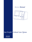
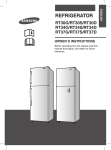
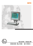
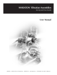
Manual
Work Station EExd 850 MHz
Version 1.00 / Series 17-71KD-4601
DOKUMENT\BMS00731.doc • Revision 0 / 2003-04-24
GmbH
Germany
Max-Eyth-Straße 16
97980 Bad Mergentheim
Telephone: +49 7931 597-0
Email:
[email protected]
Fax:
+49 7931 597-183 Internet: http://www.bartec.de
-2-
Contents
1.
2.
3.
General .................................................................................................................................................................3
1.1
Products forming the PC range ..................................................................................................................3
1.2
Basic installation Manual............................................................................................................................4
1.3
Mounting and disassembly of the equipment .............................................................................................4
1.4
Maintenance, Modifications and Servicing .................................................................................................4
1.5
Installation / Putting into service .................................................................................................................5
1.6
Software installation ...................................................................................................................................5
Technical Data .....................................................................................................................................................7
2.1
Data............................................................................................................................................................7
2.2
Front panel mounting Work Station EExd...................................................................................................8
Connection Cables ..............................................................................................................................................9
3.1
Overview ....................................................................................................................................................9
3.2
Terminal connections ...............................................................................................................................10
3.3
3.2.1
Supply ........................................................................................................................................10
3.2.2
EEx i-Keyboard and Mouse........................................................................................................11
3.2.3
Serial interface COM 1 (RS 232)................................................................................................12
3.2.4
Serial interface COM 2 (RS422).................................................................................................13
3.2.5
Serial interface COM 3 (RS 232)................................................................................................14
3.2.6
Serial interface COM 4 (RS 232)................................................................................................14
3.2.7
Network ......................................................................................................................................15
Connections for Installing software;..........................................................................................................16
3.3.1
Basic settings .............................................................................................................................16
3.3.2
AT-Bus / IDE ..............................................................................................................................16
3.3.3
Diskette ......................................................................................................................................16
4.
Operating Systems............................................................................................................................................17
5.
Input Apparatus.................................................................................................................................................18
5.1
Keyboard BMF 102 ..................................................................................................................................18
5.1.1 Technical Data EEx i-Keyboard................................................................................................................18
5.1.2 Installation ................................................................................................................................................18
5.1.3 Front panel mounting EEx i-Keyboard BMF 102 ......................................................................................19
DOKUMENT\BMS00731.doc • Rev. 0 / 2003-04-24 • Technical details subject to change without notice
...
-3-
1.
General
1.1
Products forming the PC range
The Work Station EExd, series 17-71KD-4601 is an industrial PC which is approved for use in zone 1 hazardous area.
The flameproof EExd type protection is used for the main enclosure with Intrinsically safe barriers added to supply and
connnect with the ancillary equipment. Flameproof cable glands are fitted to the unit for connection purposes.
The complete range consists of the following components:
EEx d-Screen enclosure
Front part of the enclosure
Typ 17-71K1-....
KEMA 98 ATEX 1246 X
EEx d-Computer
Rear part of the enclosure
Typ 17-71K2-....
KEMA 98 ATEX 2217 X
EEx i-Input apparatus
Keyboard , mouse
Typ 17-71K3-....
KEMA 98 ATEX 2558 X
Energy limiting unit
Barrier, Key board and mouse
Typ 17-71K4-1...
KEMA 98 ATEX 1988 X
Seperation module
Barrier Control buttons
Typ 17-71K4-2...
KEMA 98 ATEX 2425 X
For special conditions also see the appropriate test certificates.
DOKUMENT\BMS00731.doc • Rev. 0 / 2003-04-24 • Technical details subject to change without notice
...
-4-
1.2
Basic installation Manual
The following points must be taken into account for safe commissioning:
The Ex d enclosure with the appropriate electronic components must be mounted and connected before commissioning
in the hazardous area. The mounting of the Ex d enclosure can be carried out within the hazardous area.
1.3
•
The unit may only be opened when it is certain that no potentially explosive
atmosphere is present.
•
The blanking plugs are to be replaced by cable glands as required. When glands are
mounted instead of blanking plugs they are closed from the inside by gland stopping plugs
which must be removed before the cable is inserted.
•
The unit may only be brought into operation when it is certain that the enclosure is fully
closed and that all screws have been tightened.
•
The outer earthing connection must be integrated into the earthing system at the
place where the unit is mounted.
Mounting and disassembly of the equipment
Please ensure safe and secure mounting of the apparatus and that access is good to all of the serviceable parts.
•
The apparatus should be isolated from the supply before any assembly or dis-assembly.
During assembly, the user must ensure that a distance of at least 30mm is maintained around all of the flame gap areas
of the lids in accordance with EN60079-14. Furthermore, a free distance of at least 30mm must be maintained around
the flame gaps on the computer enclosure. This means that the overall thickness of the wall of the front panel together
with the relevant fixings elements must not be more than 14 mm.
1.4
Maintenance, Modifications and Servicing
The computer inside this Work Station EExd is a complex piece of equipment and maintenance and repair work should
only be carried out by BARTEC or a BARTEC authorised company/ repairer.
DOKUMENT\BMS00731.doc • Rev. 0 / 2003-04-24 • Technical details subject to change without notice
...
-5-
1.5
Installation / Putting into service
The delivered Work Station EExd includes an operating system (Windows NT or Windows 2000) with integrated network
In order for the Work Station EExd to be put into service, the cover of the EExd computer enclosure must be removed.
This will enable the power connections and the interface connections to be made to the correct connection terminals
(See interface connections section). Following the completion of the connections, the cover must be re-fitted and all of
the screws secured.
•
The apparatus may only be opened when the user has determined that there are no
gases present in the area.
These tasks may only be carried out by qualified / authorised personnel. The connection terminals are located , for ease,
at the top/ rear of the computer enclosure.This also ensures that the user does not work in the vicinity of the hardware.
The connection box lid is removable to allow access to the connection terminals. This enables simple , quick
terminations to be carried out for the supply and the interface units. The correct EExd cable glands must be fitted. The
lid faces should be clean and all of the lid screws must be fitted and tightened equally , when the lid is replaced prior to
putting the computer into service.
•
1.6
The apparatus must be closed before it is put in to service in the hazardous area.
Software installation
The user can install his software via the network interface.
If the user wishes to use a different (or updated) operating system on the Work Station EExd, or if he wishes to install
new software, then a disc drive or CD-ROM drive is required as a data source.
In a case like this, the flameproof enclosure must be opened. This should only be carried out either, in the safe area or
after a gas free pernmit has been issued for the area. (See section on putting the unit back into service.)
the new hardware is integrated embraced by the system via the motherboard which includes the CD-ROM or Disc drive
interface ( See section describibg interfaces) After completion of the new software installation, the Work Station can be
put into service in the Ex area.
DOKUMENT\BMS00731.doc • Rev. 0 / 2003-04-24 • Technical details subject to change without notice
...
-6-
The apparatus may only be operated on completion of asembly of the enclosure when a hazardous area is not
present.
Connection cable:
The connection cables of the intefaces and the supply are to be installed in compliance with EN 60079
General Important Information:
•
The unit may only be opened when it is certain that no potentially explosive
atmosphere is present.
•
The user is only allowed to attach the necessary cables to the terminals which are
accessible to him. Any further dismantling is only permitted to be carried out by the
manufacturer or by a person authorised by him.
•
The cables connecting to it (Ethernet interface and serial interface, etc.) are only to
be laid within buildings.
•
Any unit with a damaged glass panel must immediately be taken out of operation.
•
For Ex d cable glands or Ex d cable entries only NPT screw connections are
provided for and marked. By contrast, unmarked screw connections are made in
accordance with ISO standards.
DOKUMENT\BMS00731.doc • Rev. 0 / 2003-04-24 • Technical details subject to change without notice
...
-7-
2.
Technical Data
2.1
Data
•
•
•
•
•
Description
Type
Protection type
Ex-Certification
Display type
:
:
:
:
:
•
Computer performance
:
•
•
Hard drive
Serial Interface
:
:
•
Keyboard Interface
:
•
:
•
Floppy and CD ROM-Drive
Interfaces
Network Interface
− 15” TFT-Colour display, XGA-resolution
1024 x 768 Pixels
− Brightness 250 cd/m²
− Viewing angle: left / right 65°,bottom 50°, top 50°
− Long life CCFL-lighting
Intel Celeron 850 MHz, 256 MB DRAM
graphics board XGA, 1024 x 768 pixels, 65536 colours
2,5“, ≥ 20 GB
− Com 1: RS-232
− Com 2: RS-422 (default) optional RS 232
− Com 3: RS-232
− Com 4: RS-232
To be connected to an Intrinsically safe PS/2 MF II Keyboard
with PS/2 MouseType 17-71K3-11.1
For installing software from outside the hazardous area.
:
Ethernet, Novell NE 2000 compatible. 100 BaseT
•
•
Operating system
Power supply voltage
:
:
•
•
•
•
•
•
•
Output
Maesurements
Weight
IP protection
IP-Rating
Ambient temperature range
Mounting options
:
:
:
:
:
:
:
Windows NT or Windows 2000 (further on request)
AC 100V to AC 120V
50 - 60 Hz or
AC 200V to AC 240V
50 - 60 Hz
ca. 60 Watt
456 x 378 x 468 mm
ca. 38 kg
IP 65 at the front, IP 54 at the back
IP 65 Front only
0 °C to +50 °C
•
Other Options
:
Work Station
17-71KD-4601
EEx d [ia] IIB T4
KEMA 98 ATEX 1246 X und KEMA 98 ATEX 2217 X
−
−
−
−
Mounted doirectly onto a swivel arm.
In a control panel with a swivel arm.
Special keyboard
Operating systems
DOKUMENT\BMS00731.doc • Rev. 0 / 2003-04-24 • Technical details subject to change without notice
...
-8-
2.2
Front panel mounting Work Station EExd
The appartaus has been designed for front panel mounting.
To ensure the unit is mounted correctly, please note the following:
•
The enclosure and the location into which the computer is to be fitted/ mounted, must be
sufficiently rigid and stable to support the weight of the unit.
•
The enclosure cut out should have all burrs removed and the overall surface should be flat.
If this is not achieved, the IP Rating of the panel could be affected.
•
It is essential to mechanically secure the computer into the enclosure with suitable fixings
to support the weight of the computer.
DOKUMENT\BMS00731.doc • Rev. 0 / 2003-04-24 • Technical details subject to change without notice
...
-9-
3.
Connection Cables
3.1
Overview
The connection cables are to be installed in accordance with EN 60079-14.
The interfaces are marked in the P.C enclosure as follows:-
X3
Supply Voltage
X4.1A COM 1 (RS 232)
X1
EEx i Keyboard and Mouse
X4.3A COM 3 (RS 232)
X4.4A COM 4 (RS 232)
X6A
Network (Ethernet 100Base-T)
X4.2A COM 2 (RS 422)
X7A
optional
for customer solutions
X9A
Disc drive
X8A
CD-ROM
parallele port for dongle
Any remaining terminals are for internal use only and must not be connected to any external cables.
DOKUMENT\BMS00731.doc • Rev. 0 / 2003-04-24 • Technical details subject to change without notice
...
- 10 -
3.2
Terminal connections
3.2.1
Supply
Terminal strip X3
Connection values
L
AC 100 V to AC 120 V
AC 200 V to AC 240 V
N
Neutral
PE
Protective earth
50 - 60 Hz or
50 - 60 Hz
• The power supply is to be fused to a maximum 16 A.
• The power supply must be supplied via a switch
• Plastic cover for terminal X3 (mains connection)
− do not damage or remove
− protects the access to terminal X1 (for intrinsically safe, electrical circuits "EEx i" for the power
limiting unit) and terminal X2A (for intrinsically safe, electrical circuits "EEx i" for the
disconnector module)
For opening: open upwards in direction of the monitor enclosure
DOKUMENT\BMS00731.doc • Rev. 0 / 2003-04-24 • Technical details subject to change without notice
...
- 11 -
3.2.2
EEx i-Keyboard and Mouse
The following functions are assigned to the individual terminals at interface X1 (keyboard and mouse):
Terminal strip (power limiting unit)
Keyboard with corresponding lead colours
Designation
Signal
BMF 12
BMF 102
X1.1
Keyboard 5V
Brown
Brown
X1.2
Tastatur Data
White
White
X1.3
Tastatur Clock
Yellow
Yellow
X1.4
Tastatur earth
Green
Green
X1.5
Screen
Screen
Screen
X1.6
Maus earth
Blue
X1.7
Maus 5 V
Red
X1.8
Maus Data
Pink
X1.9
Maus Clock
Grey
Note: If you have a separated version (Typ 17-71KD-4601) connect the keyboard at the e-box of the screen
enclosure (see connection arrangement seperated version).
Power limiting unit
• create access by opening the plastic cover
• connect at terminal X1
−
either with ready-made connection cable of the PC input unit BARTEC type 17-71K3-...1/....
−
or with cable of equivalent type (suitable for the cable entries used) and with
equivalent quality of the cable ends
• used for protecting cable leading to terminal X1 in its enclosure channel and for protection of the earth connection
cable of the power limiting unit.
DOKUMENT\BMS00731.doc • Rev. 0 / 2003-04-24 • Technical details subject to change without notice
...
- 12 -
3.2.3
Serial interface COM 1 (RS 232)
The individual terminals for this connector X4.1.A are as follows;
Connector X4.1A (COM1)
Label
Signal
X4.1A.1
DCD
X4.1A.2
DSR
X4.1A.3
RxD
X4.1A.4
RTS
X4.1A.5
TxD
X4.1A.6
CTS
X4.1A.7
DTR
X4.1A.8
RI
X4.1A.9
GND
DOKUMENT\BMS00731.doc • Rev. 0 / 2003-04-24 • Technical details subject to change without notice
...
- 13 -
3.2.4
Serial interface COM 2 (RS422)
The individual terminals for this connector X4.2.A are as follows;
The default communication setting is RS 422.
Connector X4.2.A (COM2)
Signal
Label
RS232
Factory settings
RS422
X4.2A.1
DCD
TXD-
In use.
X4.2A.2
DSR
X4.2A.3
RxD
X4.2A.4
RTS
X4.2A.5
TxD
X4.2A.6
CTS
X4.2A.7
DTR
X4.2A.8
RI
N/C
X4.2A.9
GND
N/C
N/C
TXD+
In use.
N/C
RxD+
In use.
N/C
RxD-
In use.
If RS485 is to be employed then a link has to be placed from X4.2A.1 to X4.2A.7 also a further link from X4.2A.3 to
X4.2A.5
DOKUMENT\BMS00731.doc • Rev. 0 / 2003-04-24 • Technical details subject to change without notice
...
- 14 -
3.2.5
Serial interface COM 3 (RS 232)
The individual terminals for this connector X4.3.A are as follows;
Klemmleiste X4.3A (COM3)
Label
Signal
X4.3A.1
RxD
X4.3A.2
TxD
X4.3A.3
GND
3.2.6
Serial interface COM 4 (RS 232)
The individual terminals for this connector X4.4.A are as follows;
Klemmleiste X4.4A (COM4)
Label
Signal
X4.4A.1
RxD
X4.4A.2
TxD
X4.4A.3
GND
DOKUMENT\BMS00731.doc • Rev. 0 / 2003-04-24 • Technical details subject to change without notice
...
- 15 -
3.2.7
Network
The individual terminals for network connections X6.A are as follows;
Connector X6A (Ethernet 100 Base-T)
Label
Signal
X6A.1
XMT+
X6A.2
XMT-
X6A.3
RCV+
X6A.4
NC
X6A.5
NC
X6A.6
RCV-
X6A.7
NC
X6A.8
NC
DOKUMENT\BMS00731.doc • Rev. 0 / 2003-04-24 • Technical details subject to change without notice
...
- 16 -
3.3
Connections for Installing software;
3.3.1
Basic settings
If a CD –ROM disc drive or 3.5” floppy is to be connected then they must be functional within the BIOS system. Only
then can the drives be accessed from the keyboard. For BIOS changes please refer to the User Manual PCM-6890B,
Chapter Standard CMOS Setup.
CD-ROM : “Primary-Slave”
set “TYPE” to “AUTO” and “MODE” to “AUTO”.
Diskette : “Dive A” to “1.44M, 2.5 in”„
For instructions to operate the PC from drive A: Please see user manual “BIOS FEATURES SETUP”
Set boot field BOOT SEQUENCE to A,C.
IF THE FLOPPY OR DISC DRIVES ARE REMOVED THEN ALL SETTINGS MUST BE RESTORED TO THE
ORIGINAL VALUES.
3.3.2
AT-Bus / IDE
The connection X8A is an ( upward leading) AT-bus interface and is used toconnect an IDE CD-ROM disc drive. If a CDROM disc drive is to be connected, then it is necessary to set it as a slave disc drive. The connection is via the usual
ribbon flex for AT-bus(IDE).
3.3.3
Diskette
The connection X9A is a standard floppy interface,a 3.5” disc drive may be connected to this connector .
CD-ROM
Disc drive
•
•
Pin 1
Pin 1
DOKUMENT\BMS00731.doc • Rev. 0 / 2003-04-24 • Technical details subject to change without notice
...
- 17 -
4.
Operating Systems
Information about the OEM operationg system can be taken from the software manufacturers manuals.
DOKUMENT\BMS00731.doc • Rev. 0 / 2003-04-24 • Technical details subject to change without notice
...
- 18 -
5.
Input Apparatus
5.1
Keyboard BMF 102
5.1.1
Technical Data EEx i-Keyboard
5.1.2
•
Description
:
MF II Keyboard with PS/2 mouse
•
Type
:
17-71K3-11.1
•
Type of protection
:
EEx ia IIC T4
•
Ex-Certification
:
KEMA 98 ATEX 2558 X
•
Supply via
:
Energy limiter unit as per KEMA 98 ATEX 1988 X
•
Number of keys
:
Standard MF II keyboard with PS/2 Mouse
•
Mounting possibilities
:
− Front panel mounting
optional
•
Measurements
:
− Built into a keyboard desk housing
ca. 550 x 170 x 30 mm
•
Weight
:
ca. 1,5 kg
•
IP-Rating
:
IP 65 front of unit only
•
Ambient temperature range
:
0 to 50 °C
Installation
The EExi keyboard BMF 102 is connected via an eight core cable to the energy limiting terminal block X1 in the
computer.
The cores of the cable are to be connected to the keyboard interface in the computer in accordance with paragraph
3.2.2 of the enclosed table. Please Note:- The the cable‘s screen must be connected to the screw at the rear of the
computer.
Note: If you have a separated version (Typ 17-71KD-4601) connect the keyboard at the e-box of the screen
enclosure (see connection arrangement seperated version).
DOKUMENT\BMS00731.doc • Rev. 0 / 2003-04-24 • Technical details subject to change without notice
...
- 19 -
The 8 core cable is of type LiYCY. The individual cores have the following functions;
Keyboard - Core Number Colour of core
Function
1
Brown
Keyboard supply voltage(+ 5V)
2
White
Keyboard Data transmission (Data)
3
Green
Keyboard (Ground)
4
Yellow
Keyboard synchronisation (Clock)
5
Blue
Mouse (Ground)
6
Red
Mouse Data transmission (Data)
7
Green
Mouse synchronisation (Clock)
8
Red
Mouse supply voltage (+5V)
5.1.3
Front panel mounting EEx i-Keyboard BMF 102
The apparatus is designed for front panel mounting
To ensure the unit is mounted correctly please note the following:•
The enclosure and the location into which the keyboard is to be fitted/ mounted,
must be suffciently rigid and stable to support the weight of the unit.
•
The enclosure cut out should have all burrs removed and the overall surface should be flat.
If this is not achieved, the IP Rating of the panel could be affected.
DOKUMENT\BMS00731.doc • Rev. 0 / 2003-04-24 • Technical details subject to change without notice
...