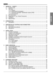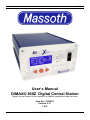
1
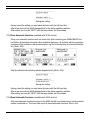
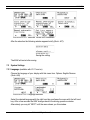
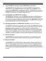
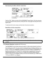
MASSOTH
User’s Manual
DiMAX® 800Z Digital Central Station
Digital Central Station for the operation of NMRA-compatible model railroads
Item No.: 8136001
Version 2.31
11/07
DiMAX® 800Z Digital Central Station
MASSOTH
Index
Page
I.
II.
III.
General Description
Summary of Functions
Layout of Terminals
3
3
4
1
1.1
1.2
1.3
1.4
Please read this first!
Safety Details and Warnings
Warranties and Guaranties
Warranty Claims
Service and Customer Support
4
4
5
5
5
2
Scope of Supply
5
3
3.1
3.2
3.3
3.4
3.4.1
3.4.2
3.5
Introduction to Digital Control with DiMAX® Digital
Database for 128 Locomotives
Locomotive Address
Speed Steps
Producing Special Functions
Producing Parallel Functions
Producing Serial Functions
Number of Locomotives in Simultaneous Operation
6
6
6
6
7
7
7
8
4
4.1
4.2
4.3
4.4
4.5
Starting Up
Connection
Display and Keyboard
Status LEDs
Connecting the Input Devices
Fuse
8
8
10
11
11
12
5
5.1
5.2
5.3
The first switch-on
The Display
Menu Prompting
The Emergency Stop Key
12
12
12
13
6
6.1
6.2
6.3
6.4
6.5
6.6
Operational Settings
Maximum Driving Current
How to log off Locomotives when using the DiMAX® Transducer
Turn Off Time in case of Short Circuit
Maximum Number of Active Locomotives
F-Functions beyond F8
Track Voltage Adjustment
13
13
14
14
15
16
16
7
Advanced System Settings
7.1 Settings of the Automatic Functions
7.1.1 Save the Status of Active Locomotives
1
DiMAX® 800Z Digital Central Station
16
17
17
MASSOTH
7.1.2
7.1.3
7.1.4
7.1.5
7.2
7.2.1
7.2.2
7.2.3
Reset Status of Active Locomotives
Store Automatic Functions
Reset Automatic Functions
Delete Locomotive Data Base
System Settings
Language
Firmware Update
System Information
17
18
18
19
20
20
21
21
8
Menu Flow Chart
22
9
9.1
9.2
Using LGB® MTS II Components with the DiMAX® Central Station
Operating Mode of the DiMAX® 600A Transducer
Managing Speed Steps in the DiMAX® 600A Transducer
23
23
23
10 Advanced Functions
10.1 Demonstration Mode
10.2 Automatic Functions
23
23
24
11
11.1
11.2
11.3
11.4
11.5
Software Update
Connect your PC to the DiMAX® Central Station
Update Program
Software of DiMAX® Components
Start Update Function of the DiMAX® Central Station
Execute the Update
25
26
26
26
26
27
12
12.1
12.2
12.3
12.4
12.5
13
Useful Hints
The Central Station calls for a Software Update
The Central Station cuts the Connection during Update
Hidden Service Mode for Software Update of the Central Station
Hidden Service Mode for Software Update of Bus Components
How to Update the DiMAX® Navigator and other RC Components
Glossary
30
30
30
30
30
30
31
14
15
Support
Manufacturer Information
35
35
Please read this Manual thoroughly before operating your DiMAX® Central Station
DiMAX® 800Z Digital Central Station
2
MASSOTH
I.
General Description
The DiMAX® 800Z Central Station is the optimum choice for Garden Railroaders. It is the
best combination of a powerful 8 Amps driving current, high safety standards and up to date
high end technology.
Based on the NMRA Standard the DiMAX® 800Z Central Station controls Locomotives equipped with decoders of all major manufacturers. A unique feature is the ability to produce digital
and analog signals which enables the DiMAX® 800Z to operate locomotives equipped with
older sound modules. A conversion of old models is therefore not necessary.
II.
Summary of Functions
Properties of the DiMAX® 800Z Central Station:
- Max 8 Amps Driving Current (adjustable to 2, 4 and 8 Amps)
- Supply Voltage 16 V to 24 V DC or 12 V to 18 V AC
- Separate Programming Outlet
- Voltage Limitation (Driving Voltage limited to 24 V DC)
- Adjustable Turn Off Time in case of short circuit (between 0.1 and 0.8 sec)
- Integrated Fan (Temperature Controlled)
- LCD Display (White Letters with Blue Background Lighting)
- Compatible to NMRA DCC
- Compatible to LGB® MTS
- Parallel and Serial Data Processing
- Booster Interface
- PC Interface (Protocol available for free)
- Track Voltage Adjustment (only with new Hardware)
System Properties:
- 10239 Locomotive Addresses
- 14/28/128 Speed Steps
- 2048 Switch Addresses
- 2048 Feed Back Addresses
- Data Base of 128 Preconfigured Locomotives (Input with handheld Controller)
- 32 Locomotives simultaneously controllable (other systems do 8 or 12 Locos)
- Automatic Function without PC (using Feedback Interface and Train Detection Module)
- Write CV (direct/indirect)
- Read CV
- Register Programming
- PoM (Program on Main / Programming on Track)
- LGB® MTS Components usable (via Transducer)
- Automatic Speed Step Scaling (14/28/128) with LGB® Components
3
DiMAX® 800Z Digital Central Station
MASSOTH
Note: The functional range of the DiMAX® 800Z Central Station is being updated on a
regular basis. Suggestions are welcome. The DiMAX® 800Z Central Station can be easily
kept up to date using the Update Function.
III.
Layout of Terminals
- Mains Power Supply (16 V to 24 V DC or 12 V to 18 V AC) separately fused
- 2 Bus Outlets on the Front (e.g. for Handheld Controller)
- Track Power Terminal
- Program Terminal
- Booster Interface (on the back)
- PC Interface RS232 (for Updates and PC-Controlling)
The bus outlets for handheld controllers, RC receivers, feedback modules etc. may be
extended by an additional DiMAX® Adapter (Item No. 8138001).
1
Please read this chapter thoroughly before starting the operation!
1.1 Safety Details and Warnings
1.1.1 This Product is not suitable for children under the age of 8 years. This product may have sharp edges.
Inappropriate handling may cause injuries. Operate this product only with products posted in this
manual. Measurements and electrical data are subject to change without further notice.
1.1.2 The DiMAX® 800Z Central Station may only be used for the operation of digitally controlled model
railroads. Do never connect the bus connectors to your telephone line! This will result in irreparable and
costly damages.
1.1.3 The DiMAX® 800Z Central Station may only be operated with digital components posted in this
manual. Even if other devices may have the same connectors, an operation will not be possible and
may result in damage of the DiMAX® 800Z Central Station and other components.
1.1.4 Do not drop this product. Do not expose the DiMAX® 800Z Central Station to shocks and do not shake
it. This may result in damage.
1.1.5 Do not expose the DiMAX® 800Z Central Station to direct heat, sunlight or a damp environment. This
may affect the operation.
1.1.6 Do not open the DiMAX® 800Z Central Station. There are no user-serviceable components inside. This
will void your warranty and may result in damage.
1.1.7 Do not clean the DiMAX® 800Z Central Station with abrasive cleaners, strong acids or corrosive cleaners. Use a plastic-compatible cleaner or dry soft cloth only.
1.1.8 We stress the fact that this product is not a toy. Do never leave your children unattended when operating the DiMAX® 800Z Central Station. Children should operate this item only under supervision of
adults.
1.1.9 Never use analog transformers on the same track with digital components. This goes for the operation
of catenary lines also.
1.1.10 Keep the ventilation grilles free of obstructions. These vents are needed for cooling the DiMAX® 800Z
Central Station. Do not pour any liquids into these grilles; keep the DiMAX® 800Z Central Station in a
dry environment.
DiMAX® 800Z Digital Central Station
4
MASSOTH
1.1.11 Visually inspect your digital components regularly, remove damaged items immediately.
1.1.12 The right to change this product in accordance with technical progress is reserved by MASSOTH
ELEKTRONIK, Seeheim, Germany. We can not compensate for damages resulting from inappropriate
handling, non-observance of this manual, operation with altered or damaged items or items not suitable
for the DiMAX® 800Z Central Station. We do not compensate for damages resulting from overheating
or moisture and inappropriate opening of the housing.
1.1.13 Removing the safety label voids your warranty instantly and irrevocably.
1.2 Warranties and Guaranties
MASSOTH ELECTRONICS USA warrants this product for 1 year from the original date of
purchase. This product is warranted against defects in materials and workmanship. Peripheral component damage is not covered by this warranty. Normal wear and tear, consumer
modifications as well as inappropriate use and handling are not covered. Errors and changes
excepted.
1.3 Warranty Claims
Valid warranty claims will be serviced without charge within the warranty period. To initiate a
warranty claim, please contact your dealer or MASSOTH ELECTRONICS USA for an RMA
(Return Merchandise Authorization). MASSOTH ELECTRONICS USA cannot be responsible
for return shipping charges to our repair facility. Please include your Proof of Purchase with
the returned goods.
1.4 Service and Customer Support
For support and technical questions contact: [email protected] or call (see below).
For downloading the latest firmware update go to www.massoth.com.
Massoth Electronics USA, LLC
6585 Remington Dr.
Cumming, GA 30040
Ph. 770-886-6670
Fax 770-889-6837
2
Scope of Supply
•
•
•
DiMAX® 800Z Central Station
Multi-Connector (to connect track power, programming track and external power source)
Manual
In case any of these items is missing or damaged contact your local dealer or the
manufacturer.
5
DiMAX® 800Z Digital Central Station
MASSOTH
Note: Please keep your box and the Styrofoam parts, to ensure proper packaging in case of
shipping. If dropped, the DiMAX® 800Z Central Station can be damaged significantly.
3
Introduction to Digital Control with DiMAX® Digital
The DiMAX® Digital System complies with the NMRA DCC Standard. All digital components
that comply with this standard may be operated with the DiMAX® 800Z Central Station. The
DiMAX® 800Z Central Station works with the special functions of the LGB® MTS System and
NMRA compatible components on the same track.
3.1 Database for 128 Locomotives
One of the prominent benefits of the DiMAX® Digital System is the ability to store locomotive
data permanently such as address, speed step configuration, special functions, and the pictogram. These data are made available to all DiMAX® Navigators or other handheld controllers
connected to the DiMAX® Central Station. This data is available after every power up and will
not be lost after shut down. The names of the locomotives are generally user related and therefore stored in the handheld controller only.
The integrated database stores up to 128 locomotives permanently. All relevant locomotive
data is shown immediately after the respective address has been put in a DiMAX® Navigator.
The address, speed steps, special functions, and pictogram are displayed here. The locomotive is ready to drive without any further actions. The only thing for you to do is: select and load
the locomotive.
3.2 Locomotive Address
The DiMAX® Digital System identifies each locomotive by an address (Number 1…10239).
The numbers 1…9999 are used for regular locomotive addresses.
3.3 Speed Steps
The DiMAX® 800Z Central Station supports the usual 14, 28 and 128 speed steps defined by
the NMRA DCC Standard. The speed steps define by which number the maximum driving
current is divided. Using lower numbers result in a slow speed, the higher numbers result in
faster speeds. A decoder programmed for 14 speed steps will control the locomotive in 14
voltage steps in every direction. 28 speed steps provide 28 voltage steps, 128 speed steps
128 voltage steps respectively. For G-Scale Garden Railroading we recommend 28 speed
steps.
In case no configuration of the locomotive has been done, the DiMAX® Navigator automatically configures the locomotive to 28 speed steps. Using LGB® Components in combination
with a DiMAX® Transducer the locomotive will be controlled with 14 speed steps automatically.
DiMAX® 800Z Digital Central Station
6
MASSOTH
(See chapter 6 – LGB® MTS II Components with the DiMAX® 800Z Central Station)
Please note that in locos configured in 14 speed steps the light will not display correctly if
they are controlled with 28 speed steps. The same is true for locos defined for 28 speed
steps that are controlled with 14 speed steps. In these cases the lights of the locomotives
may flicker or may not work at all.
3.4 Producing Special Functions
The DiMAX® Digital System provides two kinds of function triggering: parallel and serial. The
selection of the respective technique is made during the locomotive configuration via the
DiMAX® Navigator or any other handheld controller.
3.4.1 Producing Parallel Functions
Parallel function triggering is standard in the NMRA DCC operation. Each function command
is sent to the locomotive directly. Pushing the F1 key releases the function 1; the F2 key releases the function 2 and so on. The functions are produced immediately after pushing the
key as there is only one single command to be sent to the locomotive.
The number of functions has been changed during the last few years. It started out with 8
functions and was changed to 16 or more functions available. The DiMAX® Digital System is
one of the few digital systems that support 16 functions according to the NMRA DCC Standard and the DiMAX® Digital System is ready to implement any further changes in the future.
3.4.2 Producing Serial Functions
Serial function triggering has a long story. Starting out as a single function triggered by one
single key, the request for multiple functions resulted in the development of serial function
triggering. As there was only one key available on the handheld controller, one had to push
the same key repeatedly to get other functions. One had to push the key once for function #1,
twice for function #2 and three times for function #3 and so on. The F1 command was sent as
a pulse string.
Example 1: The F1 key is pressed once and command #1 was sent once. Subsequently the
whistle went off.
Example 2: The F1 key is pressed 5 times and the command was sent 5 times.
Subsequently the function #5 was initiated.
The higher the number of function, the more often the key had to be pushed. Therefore the
delay between the command and the actual initiation depended on the value of the number of
the command.
7
DiMAX® 800Z Digital Central Station
MASSOTH
Normally LGB® locomotives with serial sound function processing can be upgraded to parallel functions.
3.5 Number of Locomotives in Simultaneous Operation
The DiMAX® Digital System distinguishes between active and passive locomotives. Locomotives that are controlled by a DiMAX® Navigator or other handheld controller are active. Any
command that is put into the controller is transmitted to the DiMAX® 800Z Central Station
and then sent to the locomotive.
The maximum allowable number of active locomotives can be set in the DiMAX® 800Z Central Station menu. The manufacturer’s setting is 16; a maximum of 32 locomotives is possible.
It must be pointed out that the actual number of active locomotives, that receive data from the
DiMAX® 800Z Central Station actually slow down the system as the number grows because
the Central Station has to process the data and send these data to the locomotives. The
DiMAX® 800Z Central Station handles the active locomotives in strict rotation, once it is finished with the last one it starts all over with the first. Changes on the DiMAX® Navigator, e.g.
input of F3, are sent to the track immediately. This happens in a fracture of a second. The
more locomotives are there to be handled, the more data are to be processed. The Processing delay with 32 active locomotives may be up to 1.5 sec.
A locomotive signed off while driving remains active. If a locomotive that is parked and not
moving is signed off, it is not active anymore. The count of active locomotives is therefore reduced by the number of 1.
Note: The data processing load per active locomotive is extensive. This is the reason for
most of the digital systems to limit the number of active locomotives to 8 or a maximum of
12. The DiMAX® 800Z Central Stations operate with two high performance processors that
handle the data and the controlling of up to 32 active locomotives.
4
Starting Up
The chapters below will guide you through the set up and first operation of your DiMAX®
800Z Central Station. Please follow every step closely.
4.1 Connection
Take your DiMAX® 800Z Central Station out of the box and position it in an appropriate
place. The DiMAX® 800Z Central Station should not be placed close to a radiator, any other
heater or in direct sunlight to ensure sufficient ventilation and temperature range for the DiMAX® 800Z Central Station.
The ventilation outlet is on the back side and it should be kept clear of any
obstructions at all times.
DiMAX® 800Z Digital Central Station
8
MASSOTH
Illustration #1: Front view of the DiMAX 800Z
Illustration #2: Rear view of the DiMAX 800Z
Install the wires in the green multi connector, using a screwdriver, and plug it into the receptacle on the back side of the DiMAX® 800Z Central Station.
9
DiMAX® 800Z Digital Central Station
MASSOTH
Illustration #3: Wiring diagram
Important: Track power and program power must never be connected.
Plug in the Multi connector on the back side with external power source (12V…18V AC or
16V…24V DC with approx. 350 VA).
Illustration #4: Fuse, PC Interface and
Booster Connectors
4.2 Display and Keyboard
The display shows important information regarding the operation of your DiMAX® 800Z
Central Station at all times:
Number of active locomotives, present current load (Amps), maximum Amps (8 Amps or as
selected), turn off time in case of short circuit (as selected) and the measured driving voltage.
DiMAX® 800Z Digital Central Station
10
MASSOTH
Illustration #5: Display in driving mode
Use the three keys below the display to navigate through the menu. The lower line in the display shows the assignments of the keys and the function respectively.
4.3 Status LEDs
4 LEDs show the state of operation of your DiMAX® 800Z Central Station:
Power LED
(green)
Activity LED
(yellow)
Booster LED
(yellow)
Stop LED
(red)
After switch-on and after the successful internal test the
DiMAX® 800Z Central Station switches into normal
driving mode. The power LED is steadily illuminated.
The activity LED is blinking when data is being processed
and sent to components. In case of software update this LED
will blink during reception of data.
The booster LED is illuminated if a booster is connected to
the DiMAX® 800Z Central Station and the data transfer
between these components is working correctly.
The STOP LED blinks or is illuminated if an emergency stop
had been initiated by the DiMAX® 800Z Central Station or
other components.
4.4 Connecting the Input Devices
The DiMAX® 800Z Central Station features four receptacles for devices such as the DiMAX®
Navigator and other DiMAX® Components such as the DiMAX® Feedback Interface, the
DiMAX® Train Detection Module, a Switch Decoder or the DiMAX® Transducer for MTS II
Bus Components.
After the completion of the internal system test the DiMAX 800Z will power up the control bus.
Peripheral components connected to this bus will start working.
11
DiMAX® 800Z Digital Central Station
MASSOTH
4.5 Fuse
The DiMAX® 800Z Central Station powered on an external power source. The power source
is separately fused. The fuse is accessible on the back side of your DiMAX® 800Z Central
Station.
The external power is fused by a 12AT fuse.
5
First Switch-on
After the switch-on the 800Z starts booting and displays three indications one after another.
The last indication displays the serial number and the current software installed (Illustr. #6).
Illustration #6: Indications during booting
5.1 The Display
After booting the 800Z displays the main menu window for driving operation (Illustr. #7):
Illustration #7: Driving operation
5.2 Menu Prompting
The settings of the digital system are accomplished in the menu of the 800Z. Several options
are available.
Open the menu by pressing the red round button marked “MENU”. Use the three buttons to
navigate through the menu to adjust the settings (Illustr. #8).
DiMAX® 800Z Digital Central Station
12
MASSOTH
Illustration #8: Menu Prompting
5.3 The Emergency Stop Key
There are several options to initiate an emergency stop. At the 800Z Central Station (Illustr.
#9+10):
Illustration #9:
Emergency Stop
Illustration #10: Cancel
the emergency stop
The same functions are available with a DiMAX Navigator or the LGB Remote Control.
6
Operational Settings (V2.30: new menu diagram)
The set-up for the DiMAX® Digital System settings is accomplished in the Central Station
Menu. Several options are available.
6.1 Maximum Driving Current
The DiMAX®800Z Central Station provides the opportunity to limit the driving current on your
layout. The DiMAX®800Z Central Station measures the current driving Amps and cuts off the
power in case this limit is reached. The display of the 800Z as well as the display of the
DiMAX Navigator show the prevailing driving current at all times.
13
DiMAX® 800Z Digital Central Station
MASSOTH
Illustration #11: Indication of the driving current
in the 800Z
Illustration #12: Indication of the driving
current in the Navigator
The DiMAX®800Z Central Station delivers a maximum of 12 Amps. The adjustment steps are
2, 4, and 8 Amps. The keys to be pushed are shown inverted.
Illustration #13: Selection of the driving current
Adjust your driving current limit according to your actual current demand plus a little safety
margin. The current demand of a single LGB® Locomotive may vary from 0.5 to 2 Amps depending on the number of motors and the configuration.
Select the desired maximum current with the right hand key and leave the menu with the left
hand key. After a few seconds the 800Z changes back to the driving operation window. Alternatively you may hit “NEXT” until the menu shows you this window.
6.2 How to log off Locomotives when using a DiMAX® Transducer
Depending on the software version of the DiMAX® Transducer locomotives may be logged
off as active or passive. Starting with version 1.2 of the DiMAX® Transducer the log off is active with older versions the log off type may be preset. It is advisable to utilize the active log
off. (See 3.5)
6.3 Turn Off Time in Case of Short Circuit
This is a very important setting for Garden Railroaders. The DiMAX®800Z Central Station detects a short circuit and cuts off the power immediately with the Emergency Stop Function. After removal of the cause the normal operation may be reassumed.
DiMAX® 800Z Digital Central Station
14
MASSOTH
In digital operation reversing loop modules operate with short circuit detection. To prevent a
power shut off, the shut off time can be adjusted. Depending on the design of a locomotive a
short circuit may be triggered when passing a switch. Due to it's inertia and speed the locomotive slips by this critical location and drives on. During that time the driving current is limited to the maximum setting.
A cutoff time setting between 0.1 and 0.8 sec is available per menu (Illustr. #14). The manufacturer’s setting is 0.4 sec as it proved to be the optimum setting.
Illustration #14: Selection of the Turn Off Time
Select the desired turn off time with the right hand key and leave the menu with the left hand
key. After a few seconds the 800Z changes back to the driving operation window. Alternatively you may hit “NEXT” until the menu shows you this window.
6.4 Maximum Number of Active Locomotives (available with V2.11 and on)
This menu item limits the maximum number of active locomotives. The manufacturer’s setting
is “16”. You may choose a number from 8 to 32. For further information referring active
and passive locomotives see chapter 3.5.
Illustration #15: Selection of the Maximum Number of Active
Locomotives
Select the desired maximum number of active locomotives with the right hand key and leave
the menu with the left hand key. After a few seconds the 800Z changes back to the driving
operation window. Alternatively you may hit “NEXT” until the menu shows you this window.
15
DiMAX® 800Z Digital Central Station
MASSOTH
6.5 F-Functions beyond F8 (available with V2.30 and on)
This setting switches off all functions greater than F8. This facilitates the operation of old generation decoders of other manufacturers (Illustr. #16).
Illustration #16: Selection of F-Function Data
Select the desired number of F-keys with the right hand key and leave the menu with the left
hand key. After a few seconds the 800Z changes back to the driving operation window.
Alternatively you may hit “NEXT” until the menu shows you this window.
6.6 Track Voltage Adjustment (available with V2.30 and on)
This menu facilitates the adjustment of the track voltage (Illustr. #17)
Note: The track voltage adjustment is available only with the latest hardware and in
operation an external AC power source.
Illustration #17: Selection track voltage adjustment
Select the desired track voltage and leave the menu.
7
Advanced System Settings
The Advanced System Settings refer to the Advanced Functions as the Automatic Functions,
the Demonstration Mode, and the Deletion of the Locomotive Data Base and the Update
Function for the DiMAX®800Z Central Station and other digital components.
DiMAX® 800Z Digital Central Station
16
MASSOTH
7.1 Settings of the Automatic Functions
7.1.1 Save the Status of Active Locomotives
Use this menu item to save the status of your active locomotives, so your data do not get lost
when you switch off your DiMAX®800Z Central Station. Your active locomotives will be reactivated after the next power up (Illustr. #18).
Illustration #18: Selection of the Status of Active
Locomotives
After the selection the following window appears briefly (Illustr. #19):
Illustration #19:
Saving the setting
Having saved the setting you may leave the menu with the left hand key.
After a few seconds the 800Z changes back to the driving operation window.
Alternatively you may hit “NEXT” until the menu shows you this window.
7.1.2 Reset Status of Active Locomotives
In case you do not want to reactivate your stored active locomotives, you may use the reset
function in the menu. The active locomotive data will be lost thereafter (Illustr. #20).
Illustration #20: Selection “Reset operating conditions of active locos”
After the selection the following window appears briefly (Illustr. #21):
17
DiMAX® 800Z Digital Central Station
MASSOTH
Illustration #21:
Saving the setting
Having saved the setting you may leave the menu with the left hand key.
After a few seconds the 800Z changes back to the driving operation window.
Alternatively you may hit “NEXT” until the menu shows you this window.
7.1.3 Store Automatic Functions (available with V2.20 and on)
Store your automatic functions with this menu item. After restarting your DiMAX®800Z Central Station all automatic functions will be available right away, all contacts with the respective
functions will be included in the operation again; e.g. the reversing loop is functional immediately (Illustr. #22).
Illustration #22: Selection “Save Automatic Functions”
After the selection the following window appears briefly (Illustr. #23):
Illustration #23:
Saving the setting
Having saved the setting you may leave the menu with the left hand key.
After a few seconds the 800Z changes back to the driving operation window.
Alternatively you may hit “NEXT” until the menu shows you this window.
7.1.4 Reset Automatic Functions (available with V2.20 and on)
All stored automatic functions are kept in the 800Z and will be activated every time the central
station is switched on. This menu item reset all stored automatic functions (Illustr. #24).
DiMAX® 800Z Digital Central Station
18
MASSOTH
Illustration #24: Selection “Reset Automatic Functions”
After the selection the following window appears briefly (Illustr. #25):
Illustration #25:
Saving the setting
Having saved the setting you may leave the menu with the left hand key.
After a few seconds the 800Z changes back to the driving operation window.
Alternatively you may hit “NEXT” until the menu shows you this window.
7.1.5 Delete Locomotive Data Base (takes 30 sec)
Delete all saved locomotive data. The data base will be empty as in the delivery status. Deleting takes about 30 seconds, do not switch off your DiMAX®800Z Central Station during this action.
The central station will restart thereafter (Illustr. #26).
19
DiMAX® 800Z Digital Central Station
MASSOTH
Illustration #26: Selection “Delete Loco Data Base”
After the selection the following window appears briefly (Illustr. #27):
Illustration #27:
Saving the setting
The 800Z will restart after saving.
7.2 System Settings
7.2.1 Language (available with V2.11 and on)
Choose the language of your display with this menu item. Options: English/German
(Illustr. #28)
Illustration #28: Language selection
Select the desired language with the right hand key and leave the menu with the left hand
key. After a few seconds the 800Z changes back to the driving operation window.
Alternatively you may hit “NEXT” until the menu shows you this window.
DiMAX® 800Z Digital Central Station
20
MASSOTH
7.2.2 Firmware Update
The DiMAX®800Z Central Station provides this function to update the software of the
DiMAX®800Z Central Station or other DiMAX® components.
Find a detailed description of the update procedure in chapter 10.
7.2.3 System Information (available with V2.30 and on)
This menu item provides additional system information, e.g. system temperature,
memory usage of the loco data base and the automatic functions (Illustr. #29).
Illustration #29: Selection “System Information”
Hit the left hand key to leave the menu. After a few seconds the 800Z changes back to the
driving operation window. Alternatively you may hit “NEXT” until the menu shows you this
window.
21
DiMAX® 800Z Digital Central Station
MASSOTH
8
Menu Flow Chart
DiMAX® 800Z Digital Central Station
22
MASSOTH
9
Using LGB® MTS II Components with the DiMAX®800Z Central Station
Your DiMAX®800Z Central Station may be used with all DiMAX® Components of the
DiMAX® Series, e. g. the DiMAX® Navigator, and in addition with all LGB® MTS II Components using a DiMAX® 600A Transducer (Item 8138501). The DiMAX® 600A Transducer
translates the LGB® MTS II data into DiMAX® compliant bus data to ensure the operation of
LGB® MTS II Components e.g. feedback modules and others.
9.1 Operating Mode of the DiMAX® 600A Transducer
The DiMAX® 600A Transducer converts the LGB® MTS II Bus Data into DiMAX® Bus Data.
The DiMAX®800Z Central Station and the DiMAX® 600A Transducer are communicating
with each other and produce, depending on the data stored in the DiMAX®800Z Central Station, the driving commands according to the speed steps set. The DiMAX 600A Transducer requires an external power source (e.g. LGB transformer).
9.2 Managing Speed Steps in the DiMAX® 600A Transducer (avail. with V2.20 and on)
The LGB® MTS II works with 14 speed steps only as is known. The DiMAX® 600A Transducer enables you to control locomotives with more than 14 speed steps. It is able to scale the
speed steps to ensure an operation of a LGB Loco Remote in connection with the
DiMAX®800Z Central Station. This means you can operate your locomotive with 28 speed
steps even with the LGB® Loco Remote. Please note that the locomotive operated must be
configured with a DiMAX® Navigator and stored in the data base of the DiMAX® 800Z Central Station. In case the locomotive is not stored it will be operated with 14 speed steps only.
10
Advanced Functions
The DiMAX®800Z Central Station features Special Functions only a few others can offer.
Highlights are the Demonstration Mode, the Automatic Functions, and Controlling by PC.
10.1 Demonstration Mode
The DiMAX®800Z Central Station features a special mode for automatic demonstration. To
utilize this feature you have to store all active locomotives that are stored while running and
switch off the DiMAX®800Z Central Station subsequently. When the DiMAX®800Z Central
Station is switched on again all data are being loaded and all locomotives that were previously running will start running again automatically. There is no need to start every locomotive individually.
23
DiMAX® 800Z Digital Central Station
MASSOTH
Save Operating Condition of Active Locomotives
Illustration #30: Selection of the Status of Active
Locomotives
Push the “SEL.” Button and switch off the DiMAX®800Z Central Station. After the next power
up all locomotives that were previously running will start running again assuming their last assigned speed.
To deactivate this function simply reset the data of the active locomotives:
Reset Status of Active Locomotives
Illustration #31: Selection “Reset operating conditions of active locos”
Note: The 800Z uses the data of the active locomotives (See 4.5) and stores these data separately.
10.2 Automatic Functions (available with V2.20 and on)
The DiMAX®800Z Central Station features the ability to utilize simple automatic functions without making use of a PC. You may control the driving direction and switches directly for example. To capture the desired time of change in the driving direction a feedback module must
be used. You may use a DiMAX® Feedback Module (Item No. 8170001), a DiMAX® Train
Detection Module (Item No. 8170501) or in conjunction with a DiMAX® 600A Transducer a
LGB® Feedback Module (Item No. 55070) or a LGB® Train Detection Module (Item No.
55075). In case you use a feedback module you will need reed switches (e.g. LGB® Item No.
17100) and LGB® EPL Loco Magnets.
DiMAX® 800Z Digital Central Station
24
MASSOTH
You may define a total of 32 automatic functions and run up to 8 trains automatically.
Programming is carried out with a DiMAX® Navigator.
The store function enables you to store your automatic functions in the DiMAX®800Z Central
Station so that they are available after the next power up of the station.
Storing Automatic Functions:
Illustration #32: Selection “Save Automatic Functions”
Reset Automatic Functions:
Illustration #33: Selection “Reset Automatic Functions”
Note: Please find the detailed description of the programming procedure in the DiMAX®
Navigator Manual.
11
Softwareupdate
The DiMAX®800Z Central Station and connected DiMAX® Components may be updated with
the latest firmware available at any given time. The chapter below describes the steps to be
followed.
25
DiMAX® 800Z Digital Central Station
MASSOTH
11.1 Connect your PC to the DiMAX®800Z Central Station
Your PC must be connected to the DiMAX®800Z Central Station to provide a communication
between these two units. The connection is arranged by using a standard serial communication cable. For safety reasons make sure that only those components which are to be updated
are connected to the DiMAX® 800Z Central Station.
Note: Do not use a 0-modem cable as this does not provide a suitable connection.
11.2 Update Program
The update is accomplished by the “DiMAX® Update” program which is available for download on www.massoth.com for free. Please find the download page in the section “Support &
Download” subsection “Software resp. Firmware”. We recommend saving this program in a
separate folder e.g. C:\DiMAX. The update program supports automatic language recognition
and will welcome you in English or German.
11.3 Software of DiMAX® Components
The download site mentioned above also provides you with the update files for your DiMAX®
800Z Central Station and other DiMAX® Components. It is convenient to save the update files in your DiMAX folder. All update files are easily recognizable as they end with “.dimax”.
11.4 Start the Update Function of the DiMAX® 800Z Central Station
To start an update of the DiMAX® 800Z Central Station or any other DiMAX component, select the update function in the menu (Illustr. #34).
Illustration #34: Selection Firmware Update
The boot loader of the DiMAX® 800Z Central Station starts and waits for the update file to be
transmitted from the PC.
DiMAX® 800Z Digital Central Station
26
MASSOTH
11.5 Execute the Update
Having the DiMAX® 800Z Central Station ready for reception (Steps 11.1 to 11.4.) you now
start the DiMAX® Update Program on your PC: “DiMAX_Update.exe”.
The program opens with the following page:
Confirm the start page with “NEXT”
This page requests the selection of the update file for the DiMAX component to be updated.
Click “Browse” to search for the respective update file.
In case the file has been saved in the same folder as described in 11.3, the file is to be found
in: C:\DIMAX.
27
DiMAX® 800Z Digital Central Station
MASSOTH
A selection window opens. Open the folder that contains the update file, e.g. C:\DiMAX and select
the required update file by clicking “open”. The names of the files are defined by the Massoth Item
No. and the software version.
Select the com port used with your com cable and acknowledge with “NEXT”
Note: The com address (COM1, COM2, etc.) depends on the specifications of the PC used,
the number of com ports available, and the peripheral equipment used (e.g. USB-Adapter).
DiMAX® 800Z Digital Central Station
28
MASSOTH
The program shows the relevant data of the upcoming update: Firmware Version and
DiMAX® Component to be updated. A security check makes sure the DiMAX® 800Z Central
Station is ready for reception.
Click “NEXT”.
The update procedure starts and the progress is shown with a progress bar. After the update
the program confirms the successful update and closes automatically. If the DiMAX® 800Z
Central Station was updated the unit restarts and shows the new software version during the
restart.
In case you update a DiMAX® Component, e.g. the DiMAX® Navigator, make sure that only
the component to be updated is connected to the DiMAX® 800Z Central Station.
29
DiMAX® 800Z Digital Central Station
MASSOTH
12
Useful Hints
12.1 The DiMAX® 800Z Central Station calls for a Software Update
This message appears if an update was not carried out successfully or was interrupted. The
DiMAX® 800Z Central Station starts automatically in the update mode and waits for an update. Perform a new update as described in chapter 11.
12.2 The DiMAX® 800Z Central Station cuts the Connection during Update
In case the DiMAX® 800Z Central Station repeatedly cuts the connection during updating,
you must use a hidden service function to start the DiMAX® 800Z Central Station directly in
the update mode. This function is to be used if a regular update is not possible.
12.3 Hidden Service Mode for Software Update of the DiMAX® 800Z Central Station
(available with V2.12 and on)
Keep the round red button pushed while switching on the DiMAX® 800Z Central Station. The
DiMAX® 800Z Central Station will report faulty software and start the boot loader. Now the
DiMAX® 800Z Central Station waits for data to be transmitted from your PC.
Note: This service mode only works for the DiMAX® 800Z Central Station as only the core
of the Central Station is working; the data bus to the components is disconnected.
12.4 Hidden Service Mode for Software Update of Bus Components
From version V 2.3 on the DiMAX® 800Z Central Station features an additional hidden service mode for the update of DiMAX® Bus Components:
Keep the right hand key of your DiMAX® 800Z Central Station pushed while switching on the
Central Station. The DiMAX® 800Z Central Station initializes the control bus and starts the
update mode automatically.
12.5 How to Update the DiMAX® Navigator and other RC Components
(Available with V2.30 and on)
Please note that components having a RC connection can only be updated when connected
to the DiMAX® 800Z Central Station by cable. The DiMAX® Navigator must be switched off
and connected to the DiMAX® 800Z Central Station by cable to conduct the update. After
being connected by cable the DiMAX® Navigator starts automatically, no further settings are
necessary.
DiMAX® 800Z Digital Central Station
30
MASSOTH
13
31
GLOSSARY
●
Bit
Bit is short for binary digit the smallest unit of data in a computer taking a value of either
“0” or “1”. 8 bit sum up to one byte.
●
Booster
A booster is an amplifier in a DCC system to add additional track power to the layout.
●
Bus / Bus system
A bus system is the electrical connection between control components of a DCC system.
The various bus systems being currently utilized by different manufacturers are basically
not compatible.
●
Byte
A byte is a contiguous sequence of a fixed number of bits, normally eight. The decimal
value of a byte varies between “0” and “255”.
●
Central Station
The central station is the brain of a digital system. All commands, feedbacks, etc, are
processed here and then transferred to the respective components; either via an
integrated booster to the track or by a bus line to an additional booster.
●
CV - Configuration variable
In DCC decoders various settings, so-called CVs, may be defined. A CV consists of a
byte (= 8 bit) and may have a value between “0” and “255”.
●
CV-Programming, Direct CV Programming, Direct Mode (DM)
The CV setting may be changed by CV programming. Programming can be done bit-by-bit
( one of the eight bits is altered) or in bytes (the whole byte - means all 8 bit - will be
altered). The system allows a read-out of CVs as well.
●
DCC
DCC is the abbreviation for Digital Command Control. It is a standardized model railroad
digital system. Another system is e.g. Motorola. The central station and the decoders
must operate under the same system.
●
Decoder
A decoder (switch decoder, loco decoder) converts the commands of the central station
into the respective action (e.g. operate a switch, drive a motor).
DiMAX® 800Z Digital Central Station
MASSOTH
●
Digital System
A digital system is an electronic control system for multiple train operation on the same
track. In addition to the driving current commands for driving speed, deceleration, as well
as functions e.g. light on/ light off can be transferred via the track to the locomotives.
Every locomotive / car needs to have an individual digital address and they must be
equipped with digital decoders.
Currently various protocols are used but cannot be mixed.
●
Digital Address
In a digital system each loco/car or component like switches or signals need an individual
address which consists of numbers. The number of addresses varies with the digital
system used, some contain only 256 addresses, and the Massoth system contains 10239
addresses.
●
Interface
Basically an interface is the connecting component between a digital system and a
computer. In case a computer has to control a model railroad layout an interface is
necessary to control the various modules. In many digital systems an interface is already
implemented.
●
MOROP
MOROP is the Federation of the European Model Railroaders,founded 1954 and based in
Bern, Switzerland. The intention of this federation is among other things to establish the
European norm of model railroading (NEM). A work group was established to adjust the
rules and regulations of the NEM to the latest changes in technology.
●
MTS
MTS stands for Multi Train System and is the digital system of LGB. This system works
according to the DCC standards of NMRA.
●
NEM
NEM is the European norm for model railroads. This norm is to ensure a uniform standard
of couplers, tracks, switches, digital decoders and other components in the world of model
railroading. Even the different eras of model railroading are established in the NEM.
●
NMRA
NMRA=National Model Railroader Association. The NMRA sets standards for DCC
systems on the American market.
●
POM (Programming on the Main)
PoM is the name for one of the latest procedures of programming locomotives on the
main layout track during normal operation.
DiMAX® 800Z Digital Central Station
32
MASSOTH
33
●
Protocol
A protocol is a systematical arrangement in which digital commands are organized.
●
Speed Steps
The maximum power of a motor is divided into speed steps. Each speed step may be
addressed individually. The driving characteristics get smoother with the increasing
number of speed steps.
DiMAX® 800Z Digital Central Station
MASSOTH
DiMAX® 800Z Digital Central Station
34
MASSOTH
14
Support
For support and service contact your dealer or the US Branch of the manufacturer. The manufacturer’s web site provides you with the latest information and documentation concerning
your product. A helpful list of FAQs is provided. In addition the web site contains the latest
firmware versions for download. For technical questions contact
[email protected] or
[email protected].
15
Manufacturer Information
Massoth Elektronik GmbH
Frankensteiner Strasse 28
64342 Seeheim-Malchen
- GERMANY Ph. 011-49-6151-35077-0
Fax 011-49-6151-35077-44
Massoth Electronics USA
6585 Remington Dr. Suite 200
Cumming, GA 30040
Ph. 770-886-6670
Fax 770-889-6837
Cell 850-218-0709
[email protected]
Massoth® and DiMAX® are registered trademarks by Massoth Elektronik GmbH, Seeheim, Germany. LGB® is a registered trademark and property of its respective owner. All other trademarks printed are registered trademarks as well. No parts of this work may be reproduced or transmitted in any form or by any means, electronic or
mechanical, including photocopying and recording, or by any information storage or retrieval system without the prior written permission by Massoth Elektronik GmbH
unless such copying is expressly permitted by federal copyright law.
11/07 TI
35
DiMAX® 800Z Digital Central Station