1
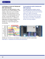
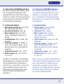
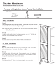
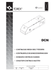
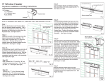
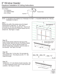
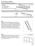
eMOTION XXL Anschlussanleitung
eMOTION XXL Installation Manual
Art.-Nr. / Item No.: 8153001
Version 2.3
Einleitende Information
Introduction
Sehr geehrte Kunden, wir empfehlen
die Produktdokumentation und vor
allem auch die Warnhinweise vor der
Inbetriebnahme gründlich zu lesen und
diese zu Beachten. In diesem Handbuch
soll der Anschluss des eMOTION XXL
Lokdekoders erläutert werden.
Dear customer, we highly recommend
to read both product manuals and
especially the warning notes thoroughly
before operation. This manual describes
the installation of the eMOTION XXL
decoder.
HINWEIS: Funktionsausgänge
Die Spannung der Licht- und Funktionsausgänge ist im Auslieferungszustand auf volle Gleisspannung
eingestellt! Vergewissern Sie sich
VOR dem Anschluss der Lampen und
Funktionsausgänge das die Spannung
entsprechend der CV-Liste richtig eingestellt ist! Für Schäden durch Nichtbeachtung dieses Hinweises übernehmen wir keine Haftung.
Note concerning the function outputs:
The function outputs are set per
default to full track voltage! Make sure
the CVs of the function outputs are set
to the appropriate value before hooking up any lights or other accessories.
Massoth cannot be responsible for
any damage if this is disregarded.
2
Inhaltsverzeichnis
Grundlegende Information...............
Funktionsumfang.............................
Lieferumfang....................................
Inbetriebnahme................................
Motor- und Gleisanschluss..............
Einbau..............................................
Erweiterte Einstellungen...................
Anschlüsse auf der Oberseite..........
Licht- und Funktionsausgänge.........
Einbau in Loks ohne Schnittstelle....
Einbau in Loks m. LGB®
Schnittstelle.....................................
Einbau in Loks m. LGB® DCC
Schnittstelle.....................................
Einbau in Loks m. Aristocraft
Schnittstelle.....................................
Anschluss SUSI/Massoth Bus.........
Technische Daten............................
Garantie, Reparatur, Kundendienst..
Hotline..............................................
Table of Contents
General Information.........................
Summary of Functions.....................
Scope of Supply...............................
Hook-Up..........................................
Motor and track connection.............
Installation.......................................
Advanced settings............................
Terminals on the upper side............
Light- and function outputs.............
Installation without interface............
Installation with LGB® decoder
interface...........................................
Installation with LGB® DCC
interface...........................................
Installation with a Aristocraft DCC
interface...........................................
Using the SUSI/Massoth bus...........
Technical Data.................................
Warranty, Service, Support..............
Hotline..............................................
4
4
5
6
6
7
7
7
9
10
10
11
12
13
13
14
15
3
1. Grundlegende Informationen
1. General Information
1.1. Funktionsumfang
1.1. Summary of Functions
Wir empfehlen beide Anleitungen
gründlich zu lesen, bevor Sie den neuen
Dekoder in Betrieb nehmen.
Einige Funktionen sind nur mit der
aktuellsten Firmware nutzbar, führen Sie
bei Bedarf ein Update durch.
• 14,28 und 128 Fahrstufen
• 256 interne Fahrstufen
• 10239 Lokadressen
• programmierbare Fahrkurve
• Anfahr-, Mittel- und Höchstgeschwindigkeit (sowie Verzögerungszeiten)
einstellbar
• Serielle und parallele Steuerung für
alle Licht- und Funktionsausgänge
incl. LGB® P-Soundupdates
• Digital- und Analogbetrieb mit automatischer Erkennung
• Kompatibel zu NMRA DCC und LGB®
MZS (alle Generationen)
• Lastregelung neuester Generation
(für Digital- und Analogbetrieb)
• Einstellbare Motorfrequenz
(70Hz - 16kHz)
• 3 Lichtanschlüsse (vorne, hinten,
innen) max. je 0,5 A
• 6 Funktionsausgänge (alle mit
konfigurierbaren Sonderfunktionen)
max. je 0,6A
• Licht- und Funktionsausgänge
dimmbar und analog aktivierbar
4
We recommend to read this manual
carefully before the decoder is installed
and operated.
Some functions require the latest firmware for availability. Please update the
decoder with the latest firmware.
• 14,28 and 128 speed steps
• 256 internal speed steps
• 10239 addresses
• Programmable driving characteristics
• Adjustable starting speed, medium
speed and maximum speed (with
acceleration/deceleration time)
• Serial and parallel control of all
light and function outputs, incl. LGB®
P-Sound updates
• Digital and analog operation with
automatic recognition
• Compatible with NMRA DCC and
LGB® MTS (all generations)
• Latest technology of load control
(digital and analog)
• Adjustable motor frequency
(70Hz - 16kHz)
• 3 light outputs (front, rear, interior)
max. 0,3 Amps each
• 6 function outputs (each
programmable with special functions)
max 0,6 Amps each
• Programmierbare Blinklicht-,
Impuls- und Taktgeberfunktion
• 2 zusätzliche Kontakteingänge
• Rangiergang (mit freier Funktionszuordnung)
• einfache Funktionszuordnung für alle
Funktionsausgänge
• alle Funktionsausgänge frei adressierbar (F1 - F16)
• Gesamtbelastbarkeit 8 Ampere
(Motorendstufe und
Funktionsausgänge)
• Motorendstufe mit 6 Ampere belastbar
• Spannungspufferanschluss für unterbrechungsfreien Lauf integriert
• Überlast- und Temperaturschutz für
Motor- und Funktionsausgänge
• Resetfunktion für alle CV-Werte
• Firmware updatefähig
• Light and function outputs may be
dimmed and activated in analog
mode
• Programmable blinking light, shorttime function, and pulse generator
function
• 2 additional contact inputs
• Switching speed (with free function
mapping)
• Easy to use function mapping
• Free command allocation of all
function outputs (F1 - F16)
• Maximum total load 8 Amps (motor
and function output)
• 6 Amps motor power amplifier
• Connector for power buffer (accessory) for smooth running integrated
• Overload and temperature protection
for motor and function outputs
• Reset function for all CV values
• Firmware easy to be updated
1.2 Lieferumfang
1.2 Scope of Supply
• eMOTION XXL Dekoder
• LGB® DCC-Schnittstellenkabel
• 2 LGB® -Getriebeanschlusskabel
(je 4 Stck.)
• 2 Schrauben 2,9 x 13 mm
• 2 Schrauben 2,9 x 19 mm
• Anschlussanleitung
• Konfigurationsanleitung
• eMOTION XXL Decoder
• LGB® DCC-interface cable
• 2 LGB® -motorblock connecting cables
(4 pcs. each)
• 2 Screws 2,9 x 13 mm
• 2 Screws 2,9 x 19 mm
• Connection manual
• Configuration manual
5
2. Inbetriebnahme
2. Hook-Up
2.1 Motor- und Gleisanschluss
2.1 Motor and track connection
Bauen Sie den Dekoder sorgfältig
nach den Anschlussplänen in dieser
Bedienungsanleitung in die Lok ein. Der
Dekoder ist generell gegen Kurzschlüsse
oder Überlastung gesichert. Werden
jedoch beim Einbau Kabel vertauscht
oder Kabel verschiedener Funktionen
(z.B. Gleis + Motor) kurzgeschlossen,
kann diese Sicherung nicht wirken und
der Dekoder wird zerstört.
Verbinden Sie das weiße (Gleis +) und
braune (Gleis -) Kabel mit dem Gleisanschluss des Getriebes.
Verbinden Sie das gelbe (Motor +) und
grüne (Motor -) Kabel mit dem Motor
im Getriebe.
Für den Einbau in Loks mit 2 Motoren
sind 2 Sätze der Getriebeanschlusskabel
im Lieferumfang enthalten.
Install your decoder in compliance with
the connecting diagram in this manual.
The decoder is protected against shorts
and excessive loads.
However, in case of a connection error
e.g. a short between a light and the
motor, this safety feature cannot work
and the decoder will be destroyed
subsequently.
Connect the white (+) and the brown
(-) wire to the track power leads of the
motor block.
Connect the yellow (+) and the green
(-) wire to the motor leads of the motor
block.
For dual motor block installation two
sets of cables are supplied with the
package.
Abbildung 1: Anschluss an Motor + Gleis
Illustration 1: Connection diagram track / motor
6
2.2 Einbau
2.2 Installation
3. Erweiterte Einstellungen
3. Advanced settings
3.1 Anschlüsse auf der Oberseite
3.1 Terminals on the upper side
Sie können den Dekoder mit dem beiliegenden Schrauben befestigen.
Beachten Sie aber hierbei unbedingt,
das Sie mit dem Schraubenkopf kein
Kabel beschädigen!
Achten Sie beim Befestigen darauf, das
kein Kurzschluss zu anderen Teilen
entsteht.
Zusätzliche Kabel für weitere Funktionen
nur mit einem kleinen Lötkolben anlöten
um Kurzschlüsse zu Bauteilen oder benachbarten Anschlüssen zu vermeiden.
Vertauschen Sie keine Anschlusskabel,
das kann zur Zerstörung führen!
Die Ränder können bei Bedarf abgebrochen werden.
Hier finden Sie alle zusätzlichen Funktionen des Dekoders.
The decoder may be mounted with the
screws provided.
Caution: Make sure that there is no
short circuit caused by the mounting
screws.
Use a small soldering iron to prevent
short circuits with other electronic
components or solder pads.
Do not mix up the wires, this may
lead to severe damage or destroy the
decoder!
To minimize the size of the decoder the
rims may be snapped off.
Here you can find all additional functions of the decoder.
Abbildung 2: eMOTION Dekoder Anschlüsse
Illustration 2: eMOTION contact assignment
7
GLGL+
MOTMOT+
GND
+ 22V
LI-V
LI-H
LI-I
A1
A2
A3
A4
A5
8
Gleis (-) Braunes Kabel zum
Getriebeanschluss
Gleis (+) Weißes Kabel zum
Getriebeanschluss
Motor (-) Grünes Kabel zum
Getriebeanschluss
Motor (+) Gelbes Kabel zum
Getriebeanschluss
Dauerhafter (-) Pol. (Z.B. für
einen Pufferanschluss)
Gemeinsamer Anschluss (+)
für Lampen- und
Funktionsausgänge
Licht vorne (-)
Licht hinten (-)
Licht innen (-)
Funktionsausgang 1 (-), div.
Blinkfunktionen, Impuls
Funktionsausgang 2 (-), div.
Blinkfunktionen, Impuls,
Wechselblinker
Funktionsausgang 3 (-), div.
Blinkfunktionen, Impuls,
Servo
Funktionsausgang 4 (-), div.
Blinkfunktionen, Impuls,
Wechselblinker
Funktionsausgang 5 (-), div.
Blinkfunktionen, Impuls,
Buffer Control
GLGL+
MOTMOT+
GND
+ 22V
LI-V
LI-H
LI-I
A1
A2
A3
A4
A5
track (-) brown wire to the
motor block
track (+) white wire to the
motor block
motor (-) green wire to the
motor block
motor (+) yellow wire to the
motor block
GND (-) e. g. for a power
buffer
Common terminal (+)
for light and function
outputs
front light (-)
rear light (-)
interior light (-)
function output 1 (-), some
flashing functions, pulse
function output 2 (-), some
flashing functions, pulse,
alternate flashing
function output 3 (-),
some flashing functions,
pulse, RC
function output 4 (-), some
flashing functions, pulse,
alternate flashing
function output 5 (-), some
flashing functions, pulse,
buffer control
Funktionsausgang 6 (-),
Taktgebersimulation
Kontakteingang 1,
Reed1
Pendelfunktion
Kontakteingang 2,
Reed2
ohne Funktion
A6
function output 6 (-),
pulse generation
contact input 1,
Reed1
shuttle operation
contact input 2,
Reed2
without function
A6
Anschluss und Benutzung der erweiterten Funktionen (Servo, Taktgeber,...)
entnehmen Sie Bitte der Konfigurationsanleitung.
Information about how to connect and
use the additional functions (e.g. RC
servo, chuff sensor…) may be found in
the Configuration Manual.
3.2 Licht und Funktionsausgänge
3.2 Light- and function outputs
Die folgende Zeichnung stellt die
Verschaltung der einzelnen Licht- und
Funktionsausgänge dar. Der Pluspol ist
der gemeinsame Pol für alle Funktionsausgänge, der Minuspol wird einzeln
für jede Funktion durch das Digitalsystem geschaltet.
Der Kontakteingang 1 ist hier auch
gegen den Pluspol zu schalten.
Illustration 3 shows the wiring diagram
of the light- and function outputs. The
plus terminal (22V) is the common
terminal for all function outputs. The
negative pole is switched individually by
the respective outputs of the decoder.
The reed contact 1 is operated the same
way.
Abbildung 3: Verschaltung der Licht- und Funktionsausgänge (Glühbirnensymbol
steht für allgemeinen Verbraucher)
Illustration 3: Connection of the light- and function outputs (the bulb symbol stands
for all regular loads)
9
3.3 Einbau in Loks ohne Schnittstelle
Generell lässt sich der Dekoder in Loks
ohne Schnittstelle besonders einfach
einbauen. Dabei wird der Dekoder mit
Hilfe der mitgelieferten Kabel direkt am
Getriebe angeschlossen. Der Aufbau des
Getriebes kann abhängig vom Hersteller
unterschiedlich sein.
ACHTUNG: Bei Piko®-G Loks sind die
Motor- und Gleisanschlüsse gegenüber LGB®-Getrieben vertauscht!
3.3 Installation without interface
Installation in a locomotive without
interface is pretty simple. The decoder
must be connected to the 4 leads of the
motor block utilizing the color coded
wires provided. The design of the motor
block may vary with the manufacturer.
Note: The motor and track connection with PIKO®-G locos is switched
compared to LGB®.
Abbildung 4: Anschluss am LGB® Getriebe
Illustration 4 : Hook-up at LGB® motor block
3.4 Einbau in Loks mit LGB®
Dekoder-Schnittstelle
Mit dem LGB® Schnittstellenkabel
(Art.-Nr. 8150602) kann der Dekoder
zusätzlich an LGB® Loks mit Dekoderschnittstelle eingebaut werden. Über
10
3.4 Installation with LGB® decoder
interface
Using the LGB® interface cable (Item
8150602) the eMOTION XXL
decoder may be installed into locomotives equipped with a decoder interface.
dieses Kabel können die Licht- und
Soundfunktionen der Lok gesteuert
werden.
The interface cable controls all lights
and other special functions of the
locomotive.
Abbildung 5: Einbau in Lok mit LGB® Dekoder-Schnittstelle
Illustration 5: Installation with LGB® decoder interface
3.5 Einbau in Loks mit LGB® DCC
Schnittstelle
Zum Anschluss des eMOTION XXL
Dekoders an eine LGB® DCC Schnittstelle schließen Sie den Dekoder gemäß
Abbildung 6 an. Benutzen Sie hierzu
das beiliegende LGB® DCC Schnittstellenkabel.
3.5 Installation with LGB® DCC
interface
The eMOTION XXL decoder comes with
a LGB® DCC interface cable which is to
be used with locomotives that provide
a LGB® DCC interface. Illustration 6
shows the wiring diagram.
Abbildung 6: Einbau in Lok mit LGB® DCC Schnittstelle
Illustration 6: Installation with a LGB® DCC interface
11
3.6 Einbau in Loks mit Aristocraft
DCC Schnittstelle
Der Einbau des eMOTION XXL Lokdekoders ist auch in ARISTOCRAFT Loks
möglich. Dabei kann auch die ARISTOCRAFT DCC Schnittstelle mit beiliegendem Schnittstellenkabel genutzt
werden. Große ARISTOCRAFT Loks
besitzen teilweise bis zu 4 Motoren.
Dabei kann der Stromverbrauch einer
Lok auf bis zu 6 Ampere steigen.
Abbildung 7 zeigt die Belegung der
Schnittstelle.
3.6 Installation with a Aristocraft
DCC interface
The eMOTION XXL decoder may be
easily installed into Aristocraft locomotives utilizing the same 10-pole interface
cable as in LGB® locomotives.
Note: Big Aristocraft locomotives may
have up to 4 driving motors and they
may draw up to 6 Amps. Illustration 7
shows the wiring diagram.
Abbildung 7: Anschluss des Dekoders an die Aristocraft DCC Schnittstelle
Illustration 7: Installation into Aristocraft locomotives
12
3.7 Anschluss SUSI/Massoth-Bus
3.7 Using the SUSI/Massoth bus
4. Technische Daten
4. Technical Data
Hinweis zur Temperatur: Um Kondenswasserbildung zu vermeiden benutzen
Sie die Elektronik bei Temperaturen
unter 0°C nur, wenn diese vorher aus
einem beheizten Raum kommt. Die
Eigenwärme des Fahrbetriebs reicht
aus um Kondenswasserbildung zu
verhindern.
Note: In case you intend to utilize this decoder below freezing temperatures, make
sure it was stored in a heated environment before operation to prevent the
generation of condensed water. The heat
generated during operation is sufficient
to prevent condensed water.
An diesen 4 poligen SUSI Stecker kann
z.B. ein gepulster Verdampfer oder
Soundmodule nach SUSI-Norm angeschlossen werden. Die Programmierung
des Anschlusses entnehmen Sie Bitte
der Konfigurationsanleitung.
• Spannungsversorgung: 0-24 V DC/
DCC (kurzzeitig max. 27V)
• Gesamtbelastbarkeit: Max. 8A
• Motorausgang: Max. 6A, 70Hz16KHz, lastgeregelt, Digital und
Analog
• Lichtausgänge: Max. je 0,6A, 22V
dimmbar
• Funktionsausgänge 1 - 6: Max. je
0,6A, 22V dimmbar (Max. 1,3A in
Summe aller Licht- und Funktionsausgänge)
• Temperaturbereich: -20 - +50°C
• Abmessungen: 65 x 33 x 16 mm
(L x B x H)
This 4-pole terminal may be used for
e.g. pulsed smoke generators or sound
modules in compliance with the SUSI
norm. Information about programming
this terminal are provided in the Configuration Manual.
• Power supply: 0-24 V DC/DCC
(momentary max. 27V)
• Total load: Max. 8 Amps
• Motor output: Max. 6 Amps,
70Hz-16KHz, load controlled,
digital and analog
• Light outputs: Max. 0,6A each, 22V
dimmable
• Function outputs 1 - 6: Max. 0,6A
each, 22V dimmable (Max. 1,3
Amps all light and function outputs
combined)
• Temperature range: -4°F - +122°F
• Measurements: 65 x 33 x 16 mm
(L x W x H)
13
4.1 Garantie, Reparatur, Kundendienst
MASSOTH gewährt die Fehlerfreiheit
dieses Produkts für ein Jahr. Die
gesetzlichen Regelungen können in
einzelnen Ländern abweichen.
Verschleißteile sind von der Garantieleistung ausgeschlossen.
Berechtigte Beanstandungen werden
kostenlos behoben. Für Reparatur- oder
Serviceleistungen übergeben Sie das
Produkt bitte Ihrem Fachhändler oder
senden es direkt an den Hersteller.
Unfrei zurückgesendete Sendungen
werden nicht angenommen. Eine Kopie
des Kaufbelegs wird vorausgesetzt. Für
Schäden durch unsachgemäße
Behandlung oder Fremdeingriff oder
Veränderung des Produkts besteht kein
Garantieanspruch. Der Anspruch auf
Serviceleistungen erlischt unwiderruflich. Irrtümer und Änderungen vorbehalten. Auf unserer Internetseite finden Sie
die jeweils aktuellen Broschüren,
Produktinformationen, Dokumentation
und Softwareprodukte rund um
MASSOTH-Produkte.
14
4.1 Warranty, Service, Support
MASSOTH warrants this product against
defects in materials and workmanship
for one year from the original date of
purchase. Other countries might have
different legal warranty situations.
Normal wear and tear, consumer
modifications as well as improper use or
installation are not covered. Peripheral
component damage is not covered by
this warranty. Valid warranty claims will
be serviced without charge within the
warranty period. For warranty service
please return the product to you dealer
or send it directly to the manufacturer.
Return shipping charges are not covered
by MASSOTH. Please include your proof
of purchase with the returned goods.
Errors and changes excepted.
Please check our web site for up to
date brochures, product information,
documentation and software updates.
4.2 Hotline
4.2 Hotline
Massoth Elektronik GmbH
Mo 14:00-17:30 sowie Do 8:00-12:00
FON +49 (0)6151-35077-38
FAX +49 (0)6151-35077-44
[email protected]
Massoth Elektronik GmbH, Germany
Mo 2:00-5:30 p.m. Thu 8:00-12:00 a.m.
FON +49 (0)6151-35077-38
FAX +49 (0)6151-35077-44
[email protected]
Serviceanfragen richten Sie bitte an:
For technical support contact:
Massoth Electronics USA
6585 Remington Dr. Suite 200
Cumming, GA 30040
9:00 a.m. to 4:00 p.m. EST Mo thru Fr
Ph. +1 770-886-6670
Fax +1 770-889-6837
[email protected]
Dieses Produkt entspricht den CE Konformitätsrichtlinien für elektrische Kleingeräte in der aktuellen Fassung.
This unit conforms to the CE Standards
RoHS
COMPLIANT
032377o
032376o
Dieses Produkt ist nach den aktuellen EG Richtlinien umgangssprachlich „bleifrei“ hergestellt und damit RoHS-konform.
This unit is manufactured according to the latest EG Standards for
lead free manufacturing conforming to RoHS Standard.
Entsorgen Sie das Produkt nicht im Hausmüll. Nutzen Sie bitte den
dafür vorgesehenen Elektroschrott.
Please dispose of according to your State regulations.
Werfen Sie das Produkt nicht in offenes Feuer oder durch Hitze
entflammbare Brennstoffe.
Do not dispose of in open fire.
15
Massoth Elektronik GmbH
Frankensteiner Str. 28 · D-64342 Seeheim · Germany
FON: +49 (0)6151-35077-0 · FAX: +49 (0)6151-35077-44
eMail: [email protected] · www.massoth.de
8153001_0610_ML
MADE
IN
GERMANY