1
Universal Datamodeling Generator
User Manual
Document
version:
Status:
Approved
Date:
29/09/2013
Authors:
Jörg Stahnke / Jan
Ross
1.
PPI AG Informationstechnologie
Moorfuhrtweg 13, 22301 Hamburg n Wall 55, 24103 Kiel
Peter-Muller-Str. 10, 40468 Düsseldorf n Wilhelm-Leuschner -Strasse 79, 60329 Frankfurt/Main
Approved
Universal Datamodeling Generator - User Manual
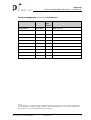
Version management for document UserGuide.docx
Name
Date
DocuComments
ment
Version
Jörg Stahnke
10/01/2014
1
Initial version
Copyright
This document has been produced by the PPI AG Informationstechnologie and is protected by copyright with respect to third parties . All rights, including translation, reprint or reproduction of the entire document or parts thereof,
shall require the consent of the PPI AG Informationstechnologie.
Document Version 1. From 29/09/2013
UserGuide.docx
2
Approved
Universal Datamodeling Generator - User Manual
Table of Contents
1
Introduction ................................................................................................................ 5
2
Installation of the feature ........................................................................................... 6
3
4
2.1
2.1.1
Requirements..............................................................................................................................6
Version 3.2.1 of the Universal Datamodeling Generator ..............................................................6
2.2
Installation of the Universal Datamodeling Generator ............................................................6
2.3
Update features ..........................................................................................................................7
Administrating data model......................................................................................... 9
3.1
3.1.1
3.1.2
3.1.3
Inheritance concept..................................................................................................................10
Basic inheritance ........................................................................................................................10
Technical names ........................................................................................................................11
Relation attributes.......................................................................................................................11
3.2
Concept package/import ..........................................................................................................12
3.3
Enter functional data elements ...............................................................................................12
3.4
3.4.1
3.4.2
3.4.3
3.4.4
3.4.5
Enter relations ..........................................................................................................................15
Enter attributes ...........................................................................................................................16
Enter indexes..............................................................................................................................17
Enter foreign keys.......................................................................................................................17
Enter triggers ..............................................................................................................................18
Enter free check constraints .......................................................................................................19
3.5
Enter sequences .......................................................................................................................19
3.6
Enter descriptions ....................................................................................................................20
3.7
3.7.1
3.7.2
3.7.3
Generate artifacts .....................................................................................................................21
Definition of required artifacts .....................................................................................................21
Executing the generation of artifacts ..........................................................................................24
Creating a main document for a customer documentation .........................................................24
3.8
3.8.1
3.8.2
3.8.3
3.8.4
3.8.5
3.8.6
Creating migration scripts for data model changes ..............................................................25
Steps of a migration....................................................................................................................25
Procedure to generate data models ...........................................................................................25
Basic principles of the generation ...............................................................................................26
Technical migration process .......................................................................................................27
Possible migration entries ..........................................................................................................29
Migration documentation ............................................................................................................31
Wizards...................................................................................................................... 34
Bibliographical reference .................................................................................................. 35
List of figures ..................................................................................................................... 36
Document Version 1. From 29/09/2013
UserGuide.docx
3
Approved
Universal Datamodeling Generator - User Manual
List of tables ...................................................................................................................... 37
Document Version 1. From 29/09/2013
UserGuide.docx
4
Approved
Universal Datamodeling Generator - User Manual
1
Introduction
This manual provides the end user with a description of how to use Xtext in Eclipse
for data modelling.
This manual describes tasks, which are important for maintaining and extending the
data model in ongoing project work.
In this manual it is assumed that the following conditions are established by the administrator of the project:
n
possible provision of an installable project feature for the installation in Eclipse
n
initial deployment of all model files to record the data model
n
definition process for recording the data model in the project
n
any project-specific changes or adaptations to the UDG
n
full definition of the project conventions
n
complete definition of all required tablespaces
This manual contains no information about model files with the extensions dbconv
(conventions) and dbphysic (tablespaces). Only the administrator has to maintain
these files.
Important note on the term "languages"
In this document the term "language" is often used. The term can occur in a variety
of contexts. Please do not mix up the various uses of the term. The following list
specifies the different usages.
1.
language as a DSL (Design structured language) in Xtext
This language describes the syntax for recording the data model. The DSL language dbdata records functional data elements and the language dbrel records relations. Further DSLs are described in the Universal Datamodeling Generator Administration Manual [1]. A project-specific DSL might also exist.
2.
language as a technical language of the generated files
This can be SQL in a specific version for the respective database (Oracle, DB2
and other) or project-specific additional languages (e.g. Java, C and other).
These languages are output languages.
3.
language of the customer-specific documentation
The customer-specific documentation is available in German, English, French,
or Spanish.
4.
programming language Xtend for project-specific generators
You can create a project-specific generator in Xtext very effectively using
Xtend. This programming language is an extension for Java which simplifies
many tasks.
Document Version 1. From 29/09/2013
UserGuide.docx
5
Approved
Universal Datamodeling Generator - User Manual
2
Installation of the feature
The data modelling with UDG in Eclipse is based on the installation of the UDG as a
feature in Eclipse. This installation is described in this section.
2.1
Requirements
2.1.1
Version 3.2.1 of the Universal Datamodeling Generator
The following software is required for this version of the UDG:
n
Eclipse 4.2.2
n
Java 1.7
n
Xtext 2.4.1
If Xtext is not installed you can install Xtext by selecting Help- >Install new
software from the <Update Site>
Http://download.eclipse.org/modelling/tmf/xtext/updates/compos
ite/releases
2.2
Installation of the Universal Datamodeling Generator
Install all of the Universal Datamodeling Generator completely by selecting Help>Install new software from the <Update Site>.
There are two different sources for the feature
1. Actual version:
http://www.ppi.de/pub/udg/
2.
Older versions can be installed from:
http://www.ppi.de/pub/udgArchive/<Timestamp>
Document Version 1. From 29/09/2013
UserGuide.docx
6
Approved
Universal Datamodeling Generator - User Manual
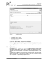
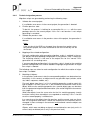
Figure 1:
Installation dialog
n
Accept the License Terms.
n
Ignore the security warning.
n
Select Restart Now.
If necessary, add the update site by using the Add button.
If there are project-specific extensions you have to install the project feature in the
same way. The exact name of the project features and the update site are provided
by your administrator.
2.3
Update features
By selecting Help- >Check for Updates a new version of the feature (UDG
and optional project-specific feature) can be installed. This is identical to a new installation (see section Installation of the Universal Datamodeling Generator on page 6).
An update can only be done in consultation with the administrator. The administrator
adjusts the model files to the necessary changes in the SVN (or other versioning
tool) and provides an updated project-specific feature.
Document Version 1. From 29/09/2013
UserGuide.docx
7
Approved
Universal Datamodeling Generator - User Manual
Then the model files need to be updated from SVN.
Document Version 1. From 29/09/2013
UserGuide.docx
8
Approved
Universal Datamodeling Generator - User Manual
3
Administrating data model
The continuous administration of the data model is done by recording information in
model files with the extension .dbdata (functional data elements) and in the model
files for relations and sequences (ending with dbrel or a specific model file extension).
Artifacts are defined and created by means of generation files (ending with
dbrel).
It is recommended to use the code completion in most cases. The keywords to be
normally used have descriptive names.
An exclusive use of descriptive name produces very long and thus confusing inputs.
Therefore, there are short tags provided for certain inputs.
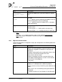
The following short tags are provided:
Tag
Description
No Entry
detection of an identifying (functional) name for the
object
[]
square brackets enclose the technical name of objects
:
The colon separates the area for recording the object
names (technical and functional) from other properties.
#
After a hash follows the project-specific extensions to
the language structure and comments for each object
(only if project-specific extensions exists).
{}
Curly braces enclose the subcomponents of an object
and define a hierarchical structure (e.g. relation -> index -> index attributes).
;
The semicolon defines a line termination.
For a clear hierarchical representation of the inputs it is recommended to use the
formatter.
In principle, the objects have a variety of properties. In order to minimise the work,
all of these properties have default values set by the administrator. An entry for a
property is only required if the property value is different from the default.
Relation attributes can inherit all properties from data elements. Data elements have
a hierarchical structure and inherit their properties.
It is recommended to build a functional structure of the data elements and to mainly
define attributes by properties inherited from data elements. This will also ensure
consistency of attribute definitions across multiple relations.
Example:
You define a data element AccountNumber (technical Name AcctNr,
numeric length 12, not null). There are two sub-elements derived from it:
Document Version 1. From 29/09/2013
UserGuide.docx
9
Approved
Universal Datamodeling Generator - User Manual
SavingAccountnummer
(length
20,
rest
inherited)
and
referenceAccount (nullable, rest inherited). The attributes are defined only by reference to the respective data elements.
When you save (with activated Build automatically in Eclipse) or when you trigger an
explicit build, a validation of all inputs is started. Possible error messages have to be
processed immediately; otherwise it is not possible to generate artifacts.
3.1
Inheritance concept
The data modelling of Xtext contains an inheritance concept. This inheritance concept significantly reduces data entry requirements. At the same time, it simplifies the
creation of generators. Due to inheritance each property of an object has always a
net value. In other words generators can simply access the property value. As a
matter of principle, NULL-pointer exceptions cannot occur.
3.1.1
Basic inheritance
During the initial creation of the project model files the administrator defines default
objects for different object types. If a property is not entered the property is inherited
from the default object.
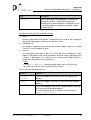
The following default objects exist:
Object
Recognizable by
relation
name of the relation is Default
tablespace
name of the tablespaces is Default
sequence
name of the sequence is the Default
primary key
primary key of the relation Default
index
first index of the relation Default
foreign key
first foreign key of the relation Default
constraint
first constraint of the relation Default
trigger
first trigger of the relation Default
free text
name of the free text is Default
standard data
name of the data element is Default
Document Version 1. From 29/09/2013
UserGuide.docx
10
Approved
Universal Datamodeling Generator - User Manual
Object
Recognizable by
type-specific data It is a sub-element of the standard data element and
has the appropriate technical data type.
Exceptions to this simple inheritance rule are described in the following chapters.
3.1.2
Technical names
If technical names of objects are not entered, this property is inherited from the functional name, i. e. the technical name is equal to the functional name.
For relation attributes the administrator can configure whether the technical name of
the attribute is inherited from the functional attribute name or from the technical
name of the associated data element.
3.1.3
Relation attributes
For properties of attributes there are two possible methods:
Case 1: Attribute has no assignment of a functional data element
In this case, the missing property is read from the type-specific default data element
which has the same technical data type as the attribute.
Case 2: Attribute has an assigned functional data element
In this case, the missing property is read from the associated data element. If the
required property is not set there either, the hierarchical parent data element is read.
If the data element on the top of the hierarchy also does not have this property the
property is read from the corresponding type-specific default data element. The
technical data type of the attribute is also previously determined via inheritance.
Should the definition of the technical data type of the attribute not be possible by
means of inheritance, it is read from the standard default data element.
Possible project-specific conventions
The administrator can set the following for each attribute property:
n
Property may be recorded in data elements.
n
Property may be recorded for relation attributes.
n
Property may be overwritten or not in hierarchical sub-elements.
Document Version 1. From 29/09/2013
UserGuide.docx
11
Approved
Universal Datamodeling Generator - User Manual
These definitions have a direct bearing on the approach in the project. If the approach defined by the administrator is not observed, this leads to error messages in
the context of the validation.
3.2
Concept package/import
All model files contain a section regarding packages and imports at the beginning.
Example:
package de.ppi.udg.generator.example.default;
import de.ppi.udg.generator.example.default.*;
Package and import definitions can be used in exactly the same way as in Java.
The entry package defines the package to which this model file belongs.
In Xtext, all functional names are entered as full qualified names. The full qualified
name of an object consists of the following components:
n
package name of the model file
n
names of all hierarchical parent objects
n
name of the original object
The fully qualified name of a relation Olsen, located in the module Egon and in the
model file with package dk.olsenbande is dk.olsenbande.Egon.Olsen.
Imports define the names to refer to objects. It is possible to use fully qualified
names for references. References with partially qualified names are only possible if
the corresponding imports are defined.
For example, if the relation Olsen should be referenced by the name Olsen in a
foreign key definition the import dk.olsenbande.egon.* is required.
An arbitrary number of imports is allowed. An import must always end with the *
character.
3.3
Enter functional data elements
Note:
Do not mix up the functional data elements with the technical data types
defined by the administrator in the context of the project conventions.
Functional data elements have a hierarchical tree structure.
When a data element has no further sub-elements the line ends with a semicolon.
Otherwise the sub-elements are enclosed in curly braces.
Document Version 1. From 29/09/2013
UserGuide.docx
12
Approved
Universal Datamodeling Generator - User Manual
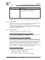
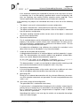
Figure 2:
Structure of inputs for functional data elements
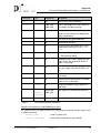
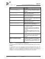
The following table lists all properties of data elements. Only Certain properties influence the generation of artifacts for selected databases.
Properties of data elements
Parameter
Tag
Databases
Description
-
all
functional name of the data element
[]
all
technical name of the data element
Type
all
technical data type
()
all
length of the technical format (only for
technical data types with variable
length)
notNull
-
all
attribute must not be null
Nullable
-
all
attribute can be null
logYes
-
DB2 LUW
DB2 z/OS
data from lob columns are logged
logNo
-
DB2 LUW
DB2 z/OS
data from lob columns are not logged
compactNo
-
DB2 LUW
data from Lob columns are not saved in
a compact format
compactYes -
DB2 LUW
data from Lob columns are saved in a
compact format
check
All
attribute-related check constraint as a
reference to a freeText
-
There is no explicit attribute list assigned to the freeText. But there is an
implicit attribute list containing exactly
the one attribute which has an entered
or inherited value for this property.
Note:
If the technical name exceeds
the maximum length for constraints the name is built as
follows:
CHECK_<hash value of
the technical name>
Document Version 1. From 29/09/2013
UserGuide.docx
13
Approved
Universal Datamodeling Generator - User Manual
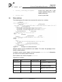
Parameter
Tag
Databases
Description
def
-
all
default value for the attribute
inlineLen
-
DB2 LUW
DB2 z/OS
returns the length of a LOB in bytes to
be stored in the base relation
autoId
-
all
attribute with an automatic ID
Values for the attribute will be generated by the database.
startWith all
start value of the generated data
increment all
increment of the data
from
all
minimum value of the data that is generated. Must not be less than startWith.
to
all
maximum value of the generated data.
0 = No maximum value
cache
all
followed by the numeric indication how
many values are cached (0 means a
cache is not used)
cycle
all
After the maximum value the generation starts again with the minimum value.
noCycle
all
data generation stops after the maximum value
order
all
The data will be generated in a sorted
order (as far as possible).
noOrder
all
The generated data have no guaranteed order.
integer
bigInt
smallInt
DB2 LUW
data type of the underlying sequence
DB2 z/OS
comment of the data element
#
Table 1:
List of data elements properties
Specific characteristics of defined default values
As a default value for data elements any string can be entered. Certain inputs have
a special meaning:
n
current_time
current system time
n
current_timestamp
current time stamp with a split second
Document Version 1. From 29/09/2013
UserGuide.docx
14
Approved
Universal Datamodeling Generator - User Manual
3.4
n
current_timestamp_autoupdate
current time stamp with a split
second updated during an SQL
Update command
n
current_date
current system date
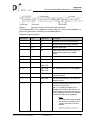
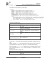
Enter relations
The following figure illustrates the structure of the entries for a relation.
Figure 3:
Example of a relation definition
Multiple relations can be combined in one module. This allows the grouping of functionally related relations.
A module used for relations begins with the keyword relations and is followed by
the name of the module and the comment.
Each relation starts with the keyword relation.
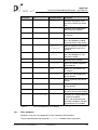
Properties of relations
parameter
tag
tag specification
description
definition of a module for relations
relations
definition of a relation
relation
Document Version 1. From 29/09/2013
-
functional name of the relation
[]
technical name of the relation
UserGuide.docx
15
Approved
Universal Datamodeling Generator - User Manual
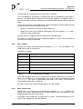
parameter
tag
tag specification
description
partition
reference to partition structure of the relation (for future
use)
tablespace
reference to the tablespace
definition of the relation
numRows
expected number of rows in
the relation
noCache/cache determines whether the relation in the database should
be permanently in the cache
compress /
noCompress
specifies whether the relation
is to be compressed in the
database
noVolatile /
volatile
determines whether the relation in the database is considered as volatile
#
comment of the relation
attributes
defines all relation attributes
with properties
index
defines a list of indexes for
the relation
foreignKey
defines a list of foreign keys
for the relation
primaryKey
defines a primary key for the
relation
trigger
a list of the triggers defined
for the relation
constraints
defines a list of freely definable constraints for the relation
relationDocRef
reference to a relation defined
in a different module
causes the referenced relation to be included in the documentation for this module
Table 2:
3.4.1
List of all properties of a relation
Enter attributes
Attributes have the same properties as the functional data elements.
They are defined after the keyword attributes between two curly braces.
Document Version 1. From 29/09/2013
UserGuide.docx
16
Approved
Universal Datamodeling Generator - User Manual
The definition of an attribute always ends with a semicolon.
The list of properties of attributes is identical with the list of properties of the data elements (see section Enter functional data elements, page 12). In addition, there is
only the possibility to enter a reference to a functional data element directly after the
colon.
Due to the inheritance rules explained in section Inheritance concept, page 10 there
are two minimum inputs defined for attributes:
n
Specify a reference to a functional data element or
n
Specify the name of the attribute and directly with the keyword type a reference to a technical data type
All other entries are optional and will override the inherited values.
The colon as a separator for names and other properties as well as the semicolon at
the end must always be specified.
3.4.2
Enter indexes
Indexes of a relation are entered after the keyword indexes. A list of indexes is entered within a pair of curly braces.
Properties of indexes
Tag
Description
-
name of the Index
cluster
if present, it is a clustered index
unique
when set, the index is unique
primaryKey
when set, the index is the primary key of the relation
{}
defines a list of attributes of the index
#
comment of the index
Table 3:
List of all properties of an index
Each index attribute consists of a reference to an relation attribute or a free text, to
which a list of attributes in round brackets is passed, as well as an optional keyword
descending. (This causes a descending sort order in the index). The input of an
index attribute ends with a semicolon.
By means of free texts function-based indexes can be created.
3.4.3
Enter foreign keys
Foreign keys of a relation are entered after the keyword foreignKey.Within curly
braces a list of pairs of attributes of the relation (child relation) and attributes of the
referenced parent relation are entered.
In principle, each foreign key also generates an index. Therefore foreign keys also
have all of the properties that have indexes.
Document Version 1. From 29/09/2013
UserGuide.docx
17
Approved
Universal Datamodeling Generator - User Manual
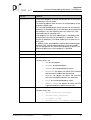
Additional properties of foreign keys
Tag
Description
->
parent relation referenced by the foreign key
create / noCreate defines whether the foreign key is generated in artifacts
A foreign key with noCreate is not created in the databases.
createIndex /
noIndex
defines whether an index is created for the attributes of the
foreign key
onDeleteNoAction
specifies that there is no cascading action for a delete SQL
command
onDeleteCascades
specifies that a delete SQL command will delete the data in
the child relation cascading
onDeleteNullifies specifies that a delete SQL command will set the data in
the child relation to null cascading
Table 4:
List of all properties of a foreign key
Each pair of foreign key attributes consists of a reference to an attribute of the relation, the keyword ->, a reference to a primary key field of the parent relation, as well
as an optional keyword descending. (This causes a descending sort order in the
index). The input ends with a semicolon.
3.4.4
Enter triggers
Triggers of a relation are entered after the keyword trigger.
Trigger properties
Tag
Description
-
name of the trigger
BEFORE
AFTER
INSTEAD OF
point in time when the trigger is fired
After the keyword the event which triggers the trigger can
be specified (e.g. “DELETE OR UPDATE”)
FOR EACH ROW
FOR EACH
STATEMENT
frequency of the trigger (per data row or per SQL command)
when
any additional condition when the trigger is to be initiated
Reference to a
freeText
Reference to a free text, which represents the program
code of the trigger body. The reference can be passed a
list of attributes enclosed in parentheses. This list is used
to replace placeholders in the database-specific implementation code defined by the administrator.
Document Version 1. From 29/09/2013
UserGuide.docx
18
Approved
Universal Datamodeling Generator - User Manual
Tag
Description
#
comment of the trigger
Table 5:
3.4.5
List of all trigger properties
Enter free check constraints
Free check constraints of a relation are entered after the keyword constraints.
Constraints entered in this way can have a check condition freely defined by the
administrator.
Properties of check constraints
Tag
Description
-
name of the constraints
Reference to a
freeText
Reference to a free text, which represents the program
code of the condition. The reference can be passed a list of
attributes enclosed in parentheses. This list is used to replace placeholder in the database -specific implementation
code defined by the administrator.
#
comment of the constraints
Table 6:
3.5
List of all properties of a check-constraints
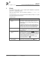
Enter sequences
Multiple sequences can be combined in one module. This allows the grouping of
functionally related sequences.
A module used for sequences begins with the keyword sequences and this is followed by the name of the module and the comment.
Sequence properties
Parameters
Tag
Description
sequences
-
definition of a module for sequences
-
name of the sequence
[]
technical name of the sequence
integer
bigInt
smallInt
technical data type that the sequence returns (only
relevant for DB2 )
from
followed by a numeric minimum value (0 means no
minimum value)
to
followed by a numeric maximum value (0 means,
no maximum)
Document Version 1. From 29/09/2013
UserGuide.docx
19
Approved
Universal Datamodeling Generator - User Manual
Parameters
Table 7:
3.6
Tag
Description
startWith
followed by a numeric start value
increment
followed by a numeric increment value
cache
followed by the numeric indication how many sequence values are cached (0 means a sequence
cache is not used)
noCycle /
cycle
Data generation stops after the maximum value
respectively after the maximum value the generation starts again with the minimum value.
noOrder /
order
The data will be generated in a sorted order (as far
as possible) respectively the generated data have
no guaranteed order.
#
comment the sequence
List of all parameters of a sequence
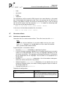
Enter descriptions
Note:
Please distinguish between descriptions and comments. Comments are
short plain text, which are also used in the DDL command create
comment. Descriptions are functional information and can be long text
formatted with html. They are only part of the data model documentation
for customers.
To enter a description a WYSIWYG HTML editor opens. By means of the editor formatted text of any length can be entered in different languages. The editor can be
opened using two different ways:
n
Mark the object with the cursor and press F3.
n
Hold down the CTRL key and click on the object with the mouse.
Before you enter a description select the language on the selection box in the header of the editor. The default language is German.
Caution:
It is possible to enter something in the HTML-view of the editor. The entered data can be saved, but only from the WYSIWYG-view. In case of
an incorrect operation, no error message is displayed!
Objects with an assigned description are displayed in bold.
Documentable objects
Object descriptions can be entered for following object types:
n
module
n
relation
n
attribute
Document Version 1. From 29/09/2013
UserGuide.docx
20
Approved
Universal Datamodeling Generator - User Manual
n
index
n
constraints
n
trigger
n
sequence
The entered texts will be saved in HTML format in the same directory as the model
files. All description files begin with a dot. That is why you do not see these files in
Eclipse using default settings. Be careful to include these files in your versioning
tool. All the file names have the extension ddldoc. In model files containing modules the name of the documentation file is:
. <Name of the model file>_<name module> .ddldoc
In the case of all other documentation files, the name is
. <Name of the model file> .ddldoc.
3.7
Generate artifacts
3.7.1
Definition of required artifacts
Generation files are used to create artifacts. These files have the suffix dbrel.
Note:
Model files with the definition of your data model also have the same
suffix dbrel. However, it is not possible to use the same file to define
both, your data model and the artifact.
A generating file is structured as follows:
n
Keyword generation followed by an opening curly brace
n
List of all of output languages (database or on a project-specific basis) for which
artifacts are to be generated. You can only use languages defined by the administrator conventions. The languages are followed (enclosed in curly braces)
by the configuration for this language. The next table lists the properties of a
configuration.
n
Keyword generationModules followed by a list of the modules to be generated in the artifact (enclosed in curly braces).
n
Optional keyword migrationRules followed by a list of specific rules for the
creation of migration scripts (see section Creating migration scripts for data model changes, page 25).
n
Closing curly brace for generation
Properties of configurations
Tag
Description
activ / inactiv
allows you to temporarily disable the generation of the artifact without deleting the definition of the artifact
Document Version 1. From 29/09/2013
UserGuide.docx
21
Approved
Universal Datamodeling Generator - User Manual
Tag
Description
outputfileSchema
name of the output file for commands that
create schema objects (relations, indexes,
etc.)
outputfileUser
name of the output file for commands that
create user objects (synonym, alias, right)
outputfileTrigger
name of the output file for commands that
create triggers
outputfileDeveloperHtmlDoku
name of the output file for the Html developer documentation
outputfileCustomerHtmlDoku
name of the output file for the Html customer documentation
documentationLanguage
language of the customer documentation
(en_DE, es_ES, en_EN., fr_FR)
nameSchema
schema name used in the created commands for relations
It is recommended to use a variable name
or placeholder
nameIndexSchema
schema name used in the created commands for indexes
It is recommended to use a variable name
or placeholder
nameUser
user name used in the created commands
for synonyms, alias, and rights
It is recommended to use a variable name
or placeholder
passwordUser
password of the database user entered in
nameUser
valid only for Oracle, postgreSQL and
mySQL
The tag is optional. If the tag is missing the
password equals the user name
privilegeUser
rights to be granted to the user
Here you can also specify a variable name
or placeholder.
maxOutputLength
maximum line width of the generated artifacts (in particular set for DB2 ZOS to maximum 72 )
noForeignKey /
createForeignKey
determines whether commands are generated to create foreign key
Document Version 1. From 29/09/2013
UserGuide.docx
22
Approved
Universal Datamodeling Generator - User Manual
Tag
Description
noForeignKeyIndex /
createForeignKeyIndex
determines whether commands are generated to create indexes based on foreign key
definitions
noTablespace /
createTablespace
determines whether commands are generated to create tablespaces
noSequence / createSequence
determines whether commands are generated to create sequences
noTable/createTable
determines whether commands are generated to create relations, unique indexes and
primary key indexes
createComment/noComment
determines whether commands are generated to create comments
noIndex/createIndex
determines whether commands are generated to create non-unique indexes
additionalFields
Here you can define an optional reference
to an additional relation.
The attributes contained in the additional
relation are added to each relation during
generation.
If the additional relation has primary or foreign keys the additional fields are also added here.
migration
optional input whether and how to create
migration scripts (see section Creating migration scripts for data model changes,
page 25)
optional any additional projectspecific configuration properties
The administrator might have defined more
configuration properties for use in projectspecific generators. These properties must
be entered as specified by the administrator.
Table 8:
List of all properties of configurations
If for certain file names empty strings are entered, the generation for these areas is
disabled.
In a generation file the same language can also be configured several times. For
example, this is useful if in the project the commands for comments are written in a
separate file. In the first configuration, all components except the comments can be
activated. In in the second configuration only the comments are activated.
Document Version 1. From 29/09/2013
UserGuide.docx
23
Approved
Universal Datamodeling Generator - User Manual
3.7.2
Executing the generation of artifacts
The generation of artifacts can be triggered in the contextual menu of files with the
extension dbrel. There are the selections generate project (creates all of the
artifacts of the project) and generate selected model (generated in the selected file defined artifacts).
Sometimes warning* files are created. These files contain warnings, if the input for
the data model contains functionalities which the database you are generating does
not know.
Example:
DB2 cannot create function-based indexes. Attributes with default system timestamp which is updating during an SQL update command are
only known in mySql server.
In PostgreSQL, there are sometimes error messages of the form invalid byte
sequence referred for encoding "UTF8", if the generated files are stored
in a different character set as defined in the database. In this case, please make appropriate character set conversions.
3.7.3
Creating a main document for a customer documentation
The customer documentation is generated in a HTML format specially designed for
Word. It must be dynamically embedded into a main document.
The document must be created on the basis of a PPI Word template.
You can use the document CustomerDocumentationMain.docx provided in the
src directory of the example project.
By means of Word, the project-specific covers, introductory chapters and others
constant texts are created.
Afterwards the various customer documentation generated in HTML format are included by means of dynamic link.
This is done by the following selections in Word:
1.
INSERT
2.
OBJECT
3.
TEXT FROM FILE
4.
Select the file
5.
AS PASTE SHORTCUT
6.
OK
It is recommended that you create a list of tables at the end of the document.
The links must be included at the heading level defined by the administrator.
After re-generating the customer documentation in the HTML format you can update
the Word document completely by pressing CTRL-A and F9.
Document Version 1. From 29/09/2013
UserGuide.docx
24
Approved
Universal Datamodeling Generator - User Manual
3.8
Creating migration scripts for data model changes
3.8.1
Steps of a migration
The generation supports a database migration in the following steps:
Step
Description
Step 1 (generated)
all additive changes (new relations, fields, etc. ) of the
database
deletes constraints which have changed
This step does not delete any data.
Functional migration
Scripts for this step in the project must be created
manually.
It is the task of this step to make functional changes to
the content of the data. This step can access both, old
(no longer existing) relations and fields as well as new
fields and relations.
As a result, it must be ensured that the data for the
new version is correct and all new and modified constraints are not violated by any data.
Step 2 (generated)
creates all new and modified constraints
removes deleted relations and attributes, i.e.. in this
step all data according which is not used anymore after the functional migration will be lost
creates changed comments
Step 3 (generated)
final validation of all changed or new constraints
user
creates/deletes/changes synonyms, rights and aliases
trigger
creates/deletes/changes triggers
The project has to decide whether a single migration script for each step is to be
generated or whether several migration scripts are to be generated per step.
If only a single migration script is desired a generating file containing all relations of
the project should be created. This is recommended in the case of small-scale projects or in case of just a few changes in the data model.
For large projects or very many data model changes several generating files should
be created for certain related groups of relations and several migration scripts are
generated. As a consequence, migration scripts can be run in parallel and the
scripts to be analysed in case of migration errors are not so extensive.
3.8.2
Procedure to generate data models
In Xtext a migration script can be generated to update an old data model for the new
program version.
Document Version 1. From 29/09/2013
UserGuide.docx
25
Approved
Universal Datamodeling Generator - User Manual
The procedure is as follows:
3.8.3
1.
Check out the previous state of the data model from the respective SVN (or
other versioning tool) branch into the current Eclipse workspace.
2.
Enable the generation of migration scripts by means of the keyword migration for the desired configurations.
3.
Choose DDL -> migrate project or DDL -> migrate selected
model in the contextual menu of the generating file. This generates the migration scripts including documentation.
Basic principles of the generation
The automatic generation of the migration scripts works according to the following
principles:
n
The documentation always contains a complete list of all net changes of the data model in Xtext.
n
The created migration scripts are always executable. The created files need not
be revised.1
In order to comply with these principles, the following compromises have been
made:
n
You may not create migration commands for all changes in the data model. This
applies, for example to changes of tablespace properties.
These changes have the status manual migration necessary in the documentation.
n
Some commands are for certain databases and can be executed only under
special conditions (e.g. rename commands). Therefore, these commands are
generated as commented commands.
These changes have the status automatically generated as comment
in the documentation. In the generated DDL the commands are marked with
Attention!!
n
Some commands depending on previously commented commands are therefore also commented. (This for example applies to a format change of a relation
attribute when the previous Rename of the relation is commented.)
These changes are marked with Attention!! in the generated DDL.
The overall target to be achieved is:
1
n
For the most common changes the migration scripts are usually fully machinegenerated.
n
No changes to database migrations will be forgotten and thus accidentally migrated and newly created data models are no longer completely identical.
n
In some cases it may be necessary to create additional scripts in addition to the
machine-generated scripts.
except the replacement of any placeholders contained
Document Version 1. From 29/09/2013
UserGuide.docx
26
Approved
Universal Datamodeling Generator - User Manual
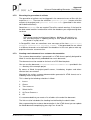
3.8.4
Technical migration process
Migration scripts are generated by performing the following steps:
1.
Validate the current project.
If a validation error occurs in the current project, the generation is aborted.
2.
Find the previous state.
To do this, the process is looking for a convention file dbconv with the same
package name as the current project. If this file is not found or is not unique
generating is canceled.
3.
Validate the previous state.
If a validation error occurs in the previous status of the project, the generation is
aborted.
Note:
If the version of the UDG has changed since the previous project status,
the previous project has to be converted to the new version by the administrator.
4.
Mapping of the related configuration.
For each configuration with generating migration scripts is enabled in the current project the corresponding configuration in the previous state is looked for.
The matching criterion is that one of the output files for the "normal" DDLgeneration has a matching name.
If no corresponding configuration in the previous state is found or the matching
previous configuration has another database language the generation of migration scripts is aborted.
The following steps are taken for each configuration for which the creation of migration scripts is enabled.
5.
Matching all objects.
In the previous and current state the corresponding objects are determined automatically. In this context, an object can be any possible input (relation, attribute, index, sequence, module, etc.).
For each object type there is a list of matching properties used to match this
type of objects. In most cases this is the functional and technical name of the
object. What are the matching properties for a special object type, can be taken
from the generated migration documentation (see section Migration documentation , page 31)
When two objects have the same value for the first matching property (mostly
functional name) these two objects are regarded as matching. If this is not the
case the second property is checked, etc.
In a normal case the objects from the previous and the current state are therefore still assigned to each other if either the functional or the technical name is
changed. Is there a change in the technical and functional name the objects are
not assigned.
Objects, which were not being assigned, are considered as new (only exists in
current state) or deleted (exists only in the previous level).
Document Version 1. From 29/09/2013
UserGuide.docx
27
Approved
Universal Datamodeling Generator - User Manual
If this automatic matching has unwanted or incorrect results by means of manual matching rules it can be explicitly specified which current and previous objects are matching (see section Possible migration entries, page 29). These
manual specifications take precedence over the automatic matching.
In the following, only objects are considered that meet at least one of the following
criteria.
n
The object is new and is referenced by the current configuration.
n
The object is deleted and is referenced from the previous configuration.
n
The object could be matched and the previous status of the object is referenced
from the previous configuration.
n
The object could be matched and the current status of the object is referenced
by the current configuration.
6.
Determine the differences.
For all matched objects and for all properties of the objects the net value of the
property in the previous and the current state is determined. This takes into account all conventions, configurations, inheritances and default values. The two
net values are compared with each other.
If an object has child objects (e.g. attributes of a relation) this evaluation is also
done recursively for all sub-objects in any hierarchical depth.
7.
Output of the complete documentation
A complete documentation of all matched objects and their properties is generated. This documentation also contains objects and properties without differences (see section Migration documentation , page 31).
At this time, the status of all properties is constant manual migration
necessary since there are still no migration DDLs being generated.
This documentation is used in case of doubt to understand the matching of objects and the calculated net values of properties and is very long.
8.
Reduction of documentation
In the existing documentation all the entries which have no different net values
and all sub-objects which do not differ from each other are cleared.
9.
generating DDL
Based on the reduced documentation with the relevant differences the necessary DDL migration commands are generated. For each analyzed difference the
status is set.
10. Consistency check of the configuration
The generated DDL is checked for consistency.
If a primary key is changed without changing all of the relations referencing this
primary key by a foreign key also contained in the configuration, the configuration is inconsistent. In this case, the generation of migration scripts is aborted
and an error file is generated.
According to the entries in the error log, the relation set assigned to the configuration has to be changed.
Document Version 1. From 29/09/2013
UserGuide.docx
28
Approved
Universal Datamodeling Generator - User Manual
11. Output of the DDL
The generated DDL is written in the corresponding scripts.
12. Output of the Delta documentation
The now existing documentation will be generated. This documentation contains the following information:
•
Which properties were changed and what are the corresponding net values?
•
Was a corresponding DDL command generated for these changes? (Status
of the change)
This documentation complete lists all changes to the data model since the previous progress report including a status.
13. Output of the manual documentation
This documentation contains only deviations with the status manual migration necessary. With their help you can check whether corresponding DDL
commands were generated for all differences. If this is not the case, additional
migration scripts must be created manually.
If this list is not empty, this may be caused by the following:
•
The DDL command for the specific database language had not (yet) implemented or such a DDL command does not exist at all for this database
language.
•
For the object in question the generation of the DDL was manually disabled
(see section Possible migration entries, page 29).
14. Output of further information
When calling the migration DDL- >migrate project a hint file may possibly
be generated with following information:
•
Which relations / sequences are not migrated by any of the activated configurations?
•
Which relations / sequences are migrated by more than one activated configuration?
If such an advice is given you have to check whether too few or too many configurations are activated for the migration.
3.8.5
Possible migration entries
In principle, all migration entries are optional. If no entries are made no migration
scripts are generated.
The minimum entry is the keyword migration (including opening and closing
curly bracket) in the database-specific configurations for which migration scripts are
to be created.
Document Version 1. From 29/09/2013
UserGuide.docx
29
Approved
Universal Datamodeling Generator - User Manual
The following example shows all possible inputs.
Meaning of migration entries
Tag
Description
migration
enables the configuration for the generation of migration scripts
ddlUser
name of the generated DDL file for the migration of
synonyms, alias and rights
ddlTrigger
name of the generated DDL file for the migration of
triggers
ddlStep1
ddlStep2
ddlStep3
name of the generated DDL file for the corresponding
step
fullDocumentation
name of the generated file for the relevant documentation of the migration
deltaDocumentation
manuellDocumentation
If a file name is missing the naming convention specified by the administrator are
used.
With the keyword rules in the configuration manual special rules for the migration
can be defined. These special rules apply only to this configuration language.
With the keyword migrationRules special rules for the migration can be defined
at the end of a generating file. These special rules apply to all configurations in this
generating file.
Meaning of the inputs for special rules
Tag
Description
eClass
fixed keyword for the object class you want to define a
special rule
Document Version 1. From 29/09/2013
UserGuide.docx
30
Approved
Universal Datamodeling Generator - User Manual
Tag
Description
ForeignKey,
Relation, Index ,
etc.
name of the object class you want to define a special
rule
match
noDDL
rule type
match specifies that the following two objects from the
current and previous level are matching
noDDL specifies that for this object DDL is not generated automatically
reference to the object in question in the current and
previous levels
new
old
In case of type match both entries are necessary.
In case of type noDDL exactly one entry is necessary.
Note:
If the tag old is used the previous status of the project have to be present in the Eclipse Workspace. Otherwise you get a validation error for
the reference.
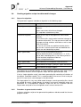
3.8.6
Migration documentation
During the generation of migration scripts per configuration the following documentation is created:
Type
Description
Full
contains all matching objects and calculated net values
of properties regardless of whether or not there are
differences
All objects referenced by the configuration either in the
current or in the previous project are listed.
Status values are not set yet.
Used for a complete overview, a control of the automatic object matching process as well as the calculated net values of all properties.
is very long
Delta
contains only objects which have at least one different
property or a sub-object with a different property.
Property values are only listed if they have different net
values.
Status values are set according to the generated DDL
commands.
Is suitable to analyse all net changes in the data model.
Document Version 1. From 29/09/2013
UserGuide.docx
31
Approved
Universal Datamodeling Generator - User Manual
Type
Description
Manually
contains only objects and properties, for which DDL
commands could (or should) not be generated
According to this documentation in exceptional cases
the required additional migration commands can be
created manually.
The documentation has the following structure
1.
Head
Contains information which project / configuration was used for the comparison
and what Eclipse project represents the previous status.
2.
Top object lists
For relations, sequences, tablespaces and relation models a top list is created.
These lists have a heading of level 1.
3.
Sub-lists
For each object contained in a top list a sub-list with all the sub-objects is generated. If sub-objects have further sub-objects for these further sub-objects also
a sub-list is generated. This is done for any hierarchy level. Sub-lists have a
heading one level lower than the parent list.
Note:
If in the Delta or Manually documentation whole sub-lists are missing,
this means that no entry fits the criteria for this sub-list.
All lists have the following columns:
Column
Contents
starting
position
name of the object in the previous level (missing for new
objects)
actual
name of the object in the current state (missing for deleted
objects)
matching by
name of the property used by the automatic object matching
missing for new and deleted objects
If a manual matching rule is used this columns contains
manual customization.
Document Version 1. From 29/09/2013
UserGuide.docx
32
Approved
Universal Datamodeling Generator - User Manual
Column
Contents
difference for
name of the property for which the comparison of the current
and previous net was made
For matching objects there are rows for each property of the
respective object type.
For new and deleted objects there are rows for all matching
properties of the object type. It can therefore be evaluated for
these objects, why the matching was not successful. If desired, add manual matching rules.
If the property has the same object type as the object to be
analysed only the name of the property is specified. This is
true for all properties in the data model you can enter an explicit value.
In addition, there are properties implicitly derived during generation of DDL and not entered directly in the data model.
For these properties the name of the property as well as the
(different) object class of the property is specified.
starting value
net property value in the previous state
actual value
net property value in the current state
type
type of property comparison
Possible values are
status
n
NEW for new objects
n
DROPPED for deleted objects
n
CHANGED for changed property values
n
RECREATED for objects for which DDL to delete
and recreate the object was generated
n
RENAMED for objects for which the technical
name has changed and which are renamed
n
EQUAL for unchanged property values
n
MANUAL IGNORE for objects for which no DDL
is generated due to special manual rules
status of the difference
Possible values are:
Document Version 1. From 29/09/2013
n
manual migration necessary
n
automatically migrated
n
no impact on DDL
n
automatically as comment generated
UserGuide.docx
33
Approved
Universal Datamodeling Generator - User Manual
4
Wizards
The creation of data models as well as project-specific adaptations to generators
and the DSL is supported by wizards.
There are several wizards. They are called by selecting New- >Other- >PPI
datamodelling.
The wizard enables an easy start with the PPI data modelling in Eclipse. It is a quick
and straight-forward test of the features.
Available wizards:
Name
Purpose
1. Data modelling initial
project
This is a fully functional sample project for data modelling in Eclipse. (without project-specific extensions)
Simultaneously, the user and the administration manual are created.
By appropriate adjustments to the specific project requirements (see the Universal Datamodeling Generator Administration Manual [1]) the sample project can
directly be used to enter your required data model.
2. Documentation update The user and the administration manual are updated.
This is important after a version update of the PPI data
modelling feature.
3. Generator extension
project
A complete Xtext project group to develop a projectspecific generator or a project-specific extension of the
DSL is created. This project group contains a working
modified example generator which can be adjusted,
according to project-specific requirements.
There are also projects to create your own projectspecific Eclipse feature.
4. Data modelling exten- It is a fully working example project to use the projectsion example
specific feature created with the previous wizard.
Document Version 1. From 29/09/2013
UserGuide.docx
34
Approved
Universal Datamodeling Generator - User Manual
Bibliographical reference
[1]
Universal Datamodeling Generator Administration Manual
Version 3.2.1
PPI AG Informationstechnologie
Document Version 1. From 29/09/2013
UserGuide.docx
35
Approved
Universal Datamodeling Generator - User Manual
List of figures
Figure 1:
Figure 2:
Figure 3:
Installation dialog....................................................................................... 7
Structure of inputs for functional data elements ....................................... 13
Example of a relation definition ................................................................ 15
Document Version 1. From 29/09/2013
UserGuide.docx
36
Approved
Universal Datamodeling Generator - User Manual
List of tables
Table 1:
Table 2:
Table 3:
Table 4:
Table 5:
Table 6:
Table 7:
Table 8:
List of data elements properties............................................................... 14
List of all properties of a relation .............................................................. 16
List of all properties of an index ............................................................... 17
List of all properties of a foreign key ........................................................ 18
List of all trigger properties ...................................................................... 19
List of all properties of a check-constraints .............................................. 19
List of all parameters of a sequence ........................................................ 20
List of all properties of configurations ...................................................... 23
Document Version 1. From 29/09/2013
UserGuide.docx
37