1
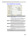
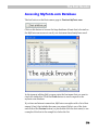
FontLab
Studio
Next-generation professional font editor –
PostScript, TrueType, Unicode, OpenType
User’s manual for Windows
5
FontLab Studio 5
Copyright ©1992-2006 by Fontlab, Ltd. All rights reserved.
Cover illustration: Paweł Jońca, pejot.com
No part of this publication may be reproduced, stored in a retrieval system, or transmitted, in
any form or by any means, electronic, mechanical, photocopying, recording, or otherwise,
without the prior written consent of the publisher. Any software referred to herein is furnished
under license and may only be used or copied in accordance with the terms of such license.
FontLab , FontLab logo, ScanFont , TypeTool , SigMaker, AsiaFont Studio, FontAudit and
VectorPaint are either registered trademarks or trademarks of FontLab, Ltd. in the United
States and/or other countries.
Apple , the Apple Logo , Mac , Mac OS , Macintosh and TrueType are trademarks of Apple
Computer, Inc., registered in the United States and other countries.
Adobe , PostScript, Photoshop, Type Manager , Illustrator, Macromedia, Fontographer, Flash
and Freehand are trademarks of Adobe Systems Incorporated, which may be registered in
certain jurisdictions.
Windows , Windows 95, Windows 98, Windows XP and Windows NT are either registered
trademarks or trademarks of Microsoft Corporation in the United States and/or other
countries.
IBM is a registered trademark of International Business Machines Corporation.
Other brand or product names are the trademarks or registered trademarks of their respective
holders.
THIS PUBLICATION AND THE INFORMATION HEREIN IS FURNISHED AS IS, IS SUBJECT TO
CHANGE WITHOUT NOTICE, AND SHOULD NOT BE CONSTRUED AS A COMMITMENT BY
FONTLAB, LTD.
FONTLAB, LTD. ASSUMES NO RESPONSIBILITY OR LIABILITY FOR ANY ERRORS OR
INACCURACIES, MAKES NO WARRANTY OF ANY KIND (EXPRESS, IMPLIED OR STATUTORY) WITH
RESPECT TO THIS PUBLICATION, AND EXPRESSLY DISCLAIMS ANY AND ALL WARRANTIES OF
MERCHANTABILITY, FITNESS FOR PARTICULAR PURPOSES AND NONINFRINGEMENT OF THIRD
PARTY RIGHTS.
User manual release 5.2 [5/2006]
2
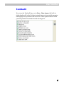
Contents
CONTENTS
INTRODUCTION
Major new features of FontLab Studio 5
Other key features of FontLab Studio
3
17
19
20
About this Manual
21
System Requirements
23
FONTLAB STUDIO USER INTERFACE
25
Basic Terms
26
Getting Started
32
Customizing FontLab Studio’s User Interface
34
Customizing Toolbars
Customizing Menus
Customizing Individual Items
Converting a Menu to a Toolbar
Customization of the Keyboard
Links to External Programs
Faster Method to Customize Commands
FontLab Studio Windows
Font Window
Glyph Window
Metrics Window
Metrics Panel
35
37
38
40
42
44
45
46
47
50
54
58
Panels
59
FontLab Studio Options
63
General Options
Font Window
Glyph Window
Metrics Window
FontAudit
Opening Type 1
Opening OpenType & TrueType
Generating Type 1
66
70
75
85
87
90
92
95
FontLab Studio 5
Generating OpenType & TrueType
Trace Options
EDITING FONTS
113
Opening Fonts
114
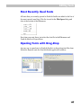
Most Recently Used Fonts
Opening Fonts with Drag-Drop
Font Formats
117
117
118
Creating a New Font
119
The Font Window
120
Glyph Naming and Character Encoding
127
Characters, Codes and Glyphs
Names Mode
Unicode Ranges
Codepages
Advanced Glyph Naming and Encoding
Using the Font Window
128
136
142
144
148
159
Navigating
Selecting
Context Menu
160
161
162
Moving Glyphs
165
Saving the Font
167
Autosave
Copying and Pasting Glyphs
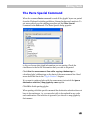
The Paste Special Command
Copying Glyphs to Another Font
Appending Glyphs to the Font
Copying Composite Glyphs
Duplicating Unicode codepoints
169
170
171
172
173
174
175
Deleting Glyphs
176
Creating New Glyphs
177
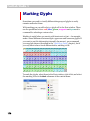
Marking Glyphs
178
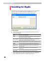
Searching for Glyphs
180
Renaming Glyphs
182
Reencoding the Font
184
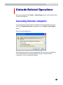
Unicode-Related Operations
187
Generating Unicode codepoints
Generating Names
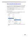
Removing Unicode Information
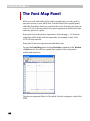
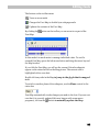
The Font Map Panel
4
100
111
187
190
191
192
Contents
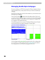
Managing Double-Byte Codepages
194
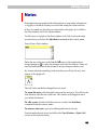
Notes
195
Sorting Glyphs
196
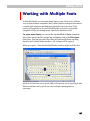
Working with Multiple Fonts
197
Windows List
Fonts Panel
Merging Fonts
Saving and Opening a Project
Saving and Opening a Workspace
198
199
202
204
205
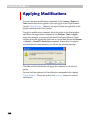
Applying Modifications
206
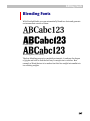
Blending Fonts
207
THE FONT HEADER
211
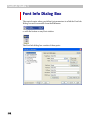
Font Info Dialog Box
212
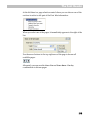
Command Bar
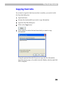
Copying Font Info
214
215
Font Names
Basic Identification and Names
Accessing MyFonts.com Database
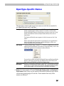
OpenType-Specific Names
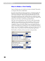
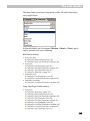
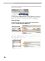
How to Make a Font Family
Non-English and Special Names
Copyright Information
Font Embedding
Designer Information
License Information
Font Identification
Version Information
Basic Font Identification
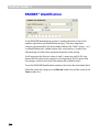
PANOSE™ Identification
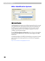
Other Identification Systems
216
217
219
221
222
228
232
233
235
236
237
237
238
240
242
Metrics and Dimensions
244
Font UPM Value
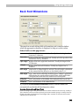
Basic Font Dimensions
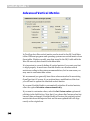
Advanced Vertical Metrics
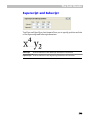
Superscript and Subscript
244
245
246
249
Encoding and Unicode
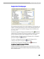
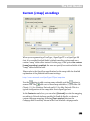
Supported Codepages
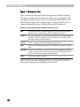
Custom [cmap] encodings
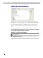
Supported Unicode Ranges
Hinting Settings
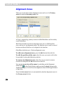
Alignment Zones
Type 1 Standard Stems
Global Hinting Parameters
250
251
253
254
255
256
258
260
5
FontLab Studio 5
Format-Specific Options
Type 1 Export Options
TrueType Export Options
TrueType Mapping Settings
Device-Dependent Metrics
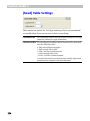
Font Smoothing Control
[head] Table Settings
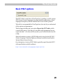
Basic PCLT options
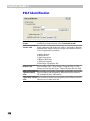
PCLT Identification
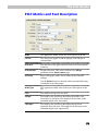
PCLT Metrics and Font Description
PCLT Codepages
Binary and custom tables
263
264
265
266
268
270
271
272
273
274
276
PRINTING AND PROOFING FONTS
277
Printing
278
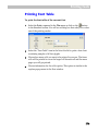
Printing Font Table
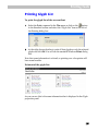
Printing Glyph List
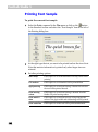
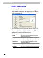
Printing Font Sample
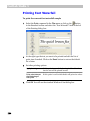
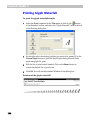
Printing Font Waterfall
Printing Glyph Sample
Printing Glyph Waterfall
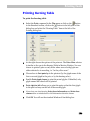
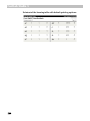
Printing Kerning Table
279
281
282
284
286
288
289
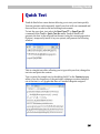
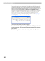
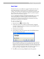
Quick Test
291
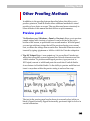
Other Proofing Methods
293
Preview panel
OpenType Features panel
Metrics Window
Hinting Tools
293
294
295
295
GENERATING FONTS
297
Relevant Font Formats
298
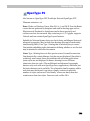
OpenType PS
Windows TrueType / OpenType TT
299
300
Windows Type 1
301
Before You Generate
302
Font Info
Character Set
Glyphs
Hints
Kerning
OpenType Layout Features
Relevant Generation Options
Generating Type 1
OpenType PS
OpenType TT
6
262
302
304
305
305
306
306
307
307
308
310
Contents
Options for Converting Fonts
312
Testing Fonts
314
THE GLYPH WINDOW
317
Glyph Window Contents
318
The Glyphs Bar
Selecting a Glyph for Editing
Creating Glyphs
Changing the View in the Glyph Window
321
323
324
325
Quick Zoom Selection
327
Tools and Operations
329
Edit Mode
331
Editing Layers
333
Easier Way to Control Editing Layers
Outline Layer
Contours
Outline Appearance
FontAudit
Moving Nodes
Using the Keyboard
Non-node editing
Changing Connection Type
Deleting Nodes
Deleting Lines and Curves
Eraser Tool
Inserting Nodes
Using the Drawing Tool
Adding Points to a Contour
Converting Segments
Breaking and Joining Outlines
Node Commands
Node Properties
Previewing Glyphs
VectorPaint Mode
Freehand Select Tool
Pen (Contour) Tool
Brush Tool
VectorPaint Options
Line Tool
Polygon Tool
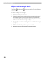
Ellipse and Rectangle Tools
Text Tool
Selections
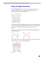
Using the Magic Wand Tool
Moving the Selection
336
337
340
348
352
356
359
360
362
363
363
364
365
366
368
369
370
371
374
376
384
386
387
388
390
392
393
394
395
396
397
398
7
FontLab Studio 5
Selection Commands
Selection Properties Panel
Copying the Selection
Transforming the Selection
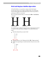
Find and Replace Outline Operation
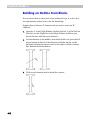
Building an Outline from Blocks
Contour-related Commands
Creating Contours
Merging and Intersecting Contours
Converting Contours
Outline Optimization
Grid Layer
428
Guidelines Layer
429
Editing Guidelines
Guidelines Popup Menu
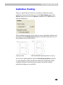
Guidelines Tracking
Guidelines Properties Panel
Meter Mode
Setting Guidelines, Anchors and Sidebearings
Mask Layer
430
432
433
434
436
438
439
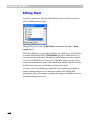
Editing Mask
Mask Operations
Assigning a Mask
440
441
442
Global Mask Layer
444
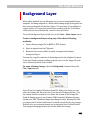
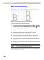
Background Layer
445
Background Positioning
Tracing Background
448
449
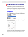
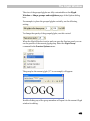
Shape Groups and Neighbors
452
Shape Groups
Neighbors
Editing Groups and Neighbors
452
454
455
Outline Operations
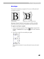
Envelope
Reversing a Contour’s Direction
Rearranging Contours
Simplifying Path
Moving Nodes
Interpolation
Metrics
Editing Metrics
Baseline Properties Panel
Metrics Properties Panel
8
399
401
402
404
409
412
417
419
424
426
427
456
457
459
460
461
462
463
467
468
470
471
Vertical Metrics
472
Hints and Links Layer
474
Contents
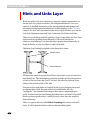
Links
Editing Hints
Hints Tracking
Editing Links
Hint and Link Popup Menu
Hint Commands
Autohinting Options
Hint Properties Panel
Link Properties Panel
475
476
478
479
480
481
482
484
484
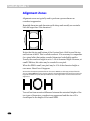
Alignment Zones
485
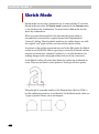
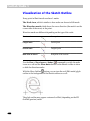
Sketch Mode
486
Visualization of the Sketch Outline
Moving Points
Changing Point Type
Removing Points
Inserting Points
Reversing Contours
Selecting Points
Moving the Selection
Transforming the Selection
Selection Operations
Breaking and Joining the Sketch Outline
Converting Sketch to Outline
Working with Composite Glyphs
Adding a Component
Decomposing
Component Positioning
Component Properties
Anchors Layer
488
489
489
489
490
490
491
493
493
493
494
494
495
496
497
498
500
501
Moving Anchors
Removing Anchors
Renaming Anchors
Changing Anchor Color
Anchor Properties
Using Anchors to Build Composites
Using the Anchors Panel
502
502
502
502
503
504
508
Creating Composites and Ligatures
511
Aliases Table
514
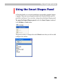
Using the Smart Shapes Panel
515
Importing and Exporting Glyphs
518
Exporting Glyphs
Preparing Artwork in Adobe Illustrator
Importing Glyphs
Manual and Automatic Scaling
Printing a Glyph
519
520
521
522
523
9
FontLab Studio 5
EDITING METRICS
525
What are Font Metrics?
526
Horizontal Glyph Metrics
Kerning
Vertical Glyph Metrics
Metrics Files
527
528
530
531
Metrics Window
Editing Modes
Metrics Ruler
Metrics Panel
Metrics Table
Context Menu
Metrics Window Toolbar
Selecting a String for Previewing or Editing
534
535
536
537
537
538
539
Selecting a Predefined Sample String
Editing a Sample String
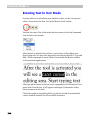
Entering Text in Text Mode
Using Drag-Drop
Navigating in the Sample String
Activating and Browsing Glyphs
Selecting Preview Size
Right-to-Left Mode
Flipped Mode
Previewing Outline and Nodes
Customizing Colors
540
541
544
545
545
546
547
548
548
549
550
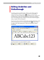
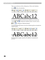
Editing Underline and Strikethrough
551
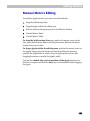
Editing Metrics
553
Manual Metrics Editing
Using the Keyboard
Using the Metrics Panel
Using the Metrics Table
The Measurement Line
Automatic Metrics Generation
555
556
557
559
563
564
Quick Save and Quick Open
566
Editing Kerning
567
Manual Kerning Editing
Using the Keyboard
Using the Metrics Panel
Using the Metrics Table
Using the Kerning Dialog
Adding Kerning Pairs
Automatic Kerning Generation
Resetting Kerning
568
568
569
570
573
575
576
578
Adjusting Metrics and Kerning
579
Class-Based Kerning
581
Class-Based Kerning and OpenType Fonts
10
532
582
Contents
Classes Panel
Class Definition
Defining the Class
Key Glyph
Rearranging Classes and Glyphs
Editing Class-Based Kerning
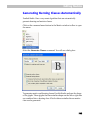
Generating Kerning Classes Automatically
Kerning Exceptions
Class Kerning Modes
Previewing Class-based Kerning
Kerning Classes and OpenType Kerning
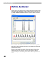
Kerning Assistance
Metrics Assistance
Editing Metrics Class Properties in Classes Panel
583
586
587
589
590
591
593
595
596
597
598
600
606
609
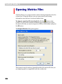
Opening Metrics Files
610
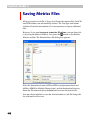
Saving Metrics Files
612
Printing
613
ACTIONS
615
The Actions Dialog Box
616
Actions
619
Contour Transformation
Hints and Guidelines Transformation
Metrics Transformation
Effects
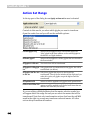
Action Set Dialog Box
Action Set Range
Action Set
Using the Preview Window
Saving and Opening an Action Set
620
628
630
633
641
642
645
646
647
Transforming Fonts
648
HINTING
651
Font Scaling, PPM
652
Coordinate Rounding, Gridfitting
654
TrueType and Type 1 Hints
655
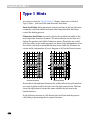
Type 1 Hints
656
Font-Level Type 1 Hints
657
Alignment Zones
Standard Stem Widths
Additional Control Data
Flex Hints
658
663
667
669
11
FontLab Studio 5
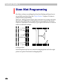
Stem Hint Programming
670
Type 1 Hinting Tool
673
Inserting and Removing Replacement Points
Adding and removing hints
Editing Hints
Autoreplacing
Preview Pixels
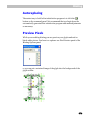
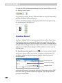
Preview Panel
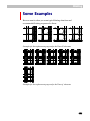
Some Examples
685
TrueType Instructions
686
Font Parameters
688
Visual TrueType Hints
689
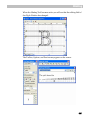
TrueType Hinting Tool
690
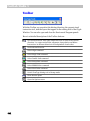
Toolbar
Layers
692
694
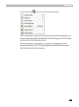
Options Panel
695
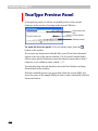
TrueType Preview Panel
696
Program Panel
698
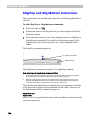
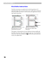
Alignment Instructions
701
Alignment Zones
Editing TrueType Alignment Zones
AlignTop and AlignBottom Instructions
Hinting Alignment Zones
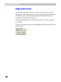
Align Instruction
Links
Standard Stems
Single Links
Double Links
701
702
704
705
706
709
710
711
716
Interpolation
720
Delta Instructions
722
Middle Delta Instructions
Final Delta Instructions
12
676
677
678
679
679
680
723
728
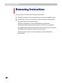
Removing Instructions
730
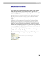
Standard Stems
731
General Options
735
Context Menu
736
Hinting Sidebearings
742
Hinting Composite Glyphs
743
Contents
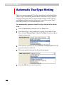
Automatic TrueType Hinting
744
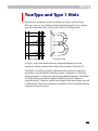
Working With Bitmaps
745
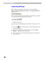
Importing Bitmaps
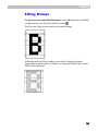
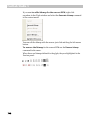
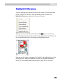
Editing Bitmaps
Highlight Differences
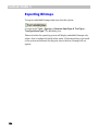
Exporting Bitmaps
746
747
749
750
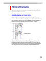
Hinting Strategies
751
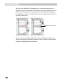
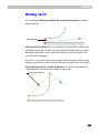
Middle Delta or Final Delta
Single Link or Double Link
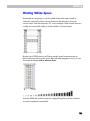
Hinting White Space
Hinting Serifs
Hinting Diagonals
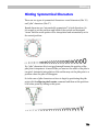
Hinting Symmetrical Characters
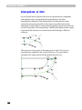
Interpolate or Not
751
753
755
757
758
759
760
Hinting Multiple Master Fonts
762
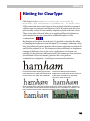
Hinting for ClearType
763
MULTIPLE MASTER FONTS
765
Multiple Master Fonts Theory
766
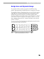
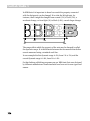
Design Axes and Dynamic Range
Standard Axes
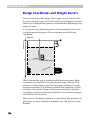
Design Coordinates and Weight Vectors
Extrapolation
Anisotropic Interpolation
The Axis Graph
Multiple Master Fonts in Studio
Creation of MM Fonts in FontLab Studio
Defining an Axis
Selecting a Master
Using an Axis Panel
Previewing the Intermediate Design
Designing Masters
Match Masters Operation
Rearranging Masters
Multiple Master Metrics
Editing Axis Settings
Removing an Axis
Multiple Master and Font Info
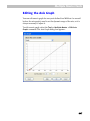
Editing the Axis Graph
Generating a Single-Master Font
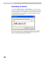
Expanding the Master
Hinting Multiple Master Fonts
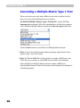
Generating a Multiple Master Type 1 Font
769
771
774
776
777
778
779
780
781
783
785
789
790
798
799
801
802
803
804
807
810
812
813
814
OPENTYPE FONTS
815
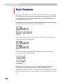
Font Features
816
Features and Lookups
819
13
FontLab Studio 5
Scripts and Languages
820
OpenType Font Formats
821
What Format to Prefer
OpenType Tables
822
822
Feature Definition Language
Language Syntax
824
OpenType and FontLab Studio
835
Importing OpenType Fonts
837
OpenType Panels
841
OpenType Panel
Adding and Removing Features
Reordering Features
Entering the Glyph and Class Names
Renaming Glyphs and Classes
Compiling the Feature Definitions
The Output Panel
OpenType Features Sample Panel
Converting the Kerning
Feature Development Process
Substitution Lookups
Single Substitution
Ligature Substitution
Alternate Substitution
Context Dependent Substitutions
841
844
844
845
846
847
849
850
852
853
854
855
857
859
860
Positioning Lookups
864
Glyph Geometry
Value Record
Single Positioning
Pair Positioning
865
866
867
868
Known Features
871
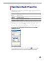
OpenType Glyph Properties
875
Caret Positioning
Generating OpenType Fonts
876
877
FontLab Studio and VOLT
880
MACRO PROGRAMMING
883
The Python Programming Language
884
Installing Python
885
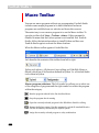
Macro Toolbar
886
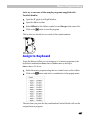
Assign to Keyboard
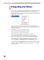
Integrating into Menus
14
823
887
888
Contents
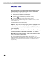
Macro Tool
890
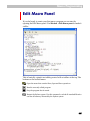
Edit Macro Panel
891
Naming the Programs
First Steps
FontLab Studio Python Classes
FontLab
Font
Glyph
Modules
INDEX
893
894
896
896
898
900
902
903
15
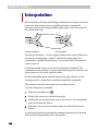
Introduction
The year 2005 marked an unusual anniversary: 30 years of digital font
technology. In 1975, at the ATypI conference in Warsaw, Peter Karow from
the Hamburg-based company URW introduced Ikarus, the world’s first
digital type design system that worked with outline fonts. Ten years later,
Adobe created PostScript and the Type 1 font format, which both became
standards in publishing. In the early 1990s, Apple introduced the TrueType
font format and the Unicode Consortium published the Unicode Standard.
Both initiatives laid the foundations for multilingual text processing and
were subsequently implemented in Microsoft Windows and Mac OS. The
turn of the millennium brought about OpenType, a significant initiative
that unified PostScript, TrueType and Unicode, and added a sophisticated
system of advanced typographic features.
The development of the digital font technology makes it easier for endusers to do text processing, typesetting and layout without sacrificing the
typographic quality and logical correctness of the text. But nothing gets lost
in Nature: using fonts is getting easier but developing them is more
complex. Apart from just drawing letters, a type designer needs to know
about encoding, hinting, layout features and various parameters that need
to be set inside of a font.
FontLab Studio 5 is the next-generation a digital font editor from
Fontlab Ltd. that allows the designer to create professional-level fonts from
start to end.
FontLab Studio 5
FontLab Studio 5 is a versatile font editor for all sorts of users. The
majority of the large font foundries and many smaller font houses use
FontLab for designing new typefaces, creating the final font products, or
both. Linguists, historians, publishers, librarians, scholars, educators,
software companies, graphic designers and even Greek Orthodox
monasteries use FontLab to create new typefaces and to extend, convert,
re-encode and otherwise modify existing fonts. If FontLab Studio is “too
much” for you, Fontlab Ltd. has simpler and more affordable products
such as the basic font editor TypeTool, the beloved classic DTP font editor
Fontographer or the universal font converter TransType.
18
Introduction
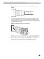
Major new features of FontLab Studio 5
Better glyph design: true tangent points, in-context glyph design with
Neighbors and Shape groups, color-customized and streamlined glyph
window
Revolutionary new metrics and kerning editing: multiline preview,
better class kerning, smart autogeneration of classes
Better bitmap and pixel font support: import BDF files and make pixel
fonts, built-in autotracing
Unicode 4.1 support: SMP codepoints, auto-generate over 2,500
accented characters from built-in definitions, new Unicode glyph
template images (from Monotype Imaging)
Improved OpenType support with better VOLT integration, roundtrip
editing of complex-script fonts, font merging, glyph suffix renaming
Better font proofing with five new printing modes and the Quick Test
feature that tests fonts with system rendering
Open and save enhancements: open installed fonts, preview fonts
before opening, generate multiple fonts in one step, opens Mac fonts on
Windows (Mac Type 1, TrueType GX/AAT) and Ikarus® files
Redesigned preferences; save, open and exchange preference profiles
and UI workspaces
Better autohinting with Flex Type 1 hints
Improved Python scripting, Python 2.4 support
19
FontLab Studio 5
Other key features of FontLab Studio
Outline editor with more than 20 tools and 200-level undo/redo
Open, edit and generate OpenType PS, TrueType / OpenType TT and
PostScript Type 1 formats with up to 6,400 characters
Open, edit and generate Multiple Master fonts
Import and export of individual glyphs in EPS format
Class-based Multiple Master-compatible metric and kerning editing
with autospacing and autokerning
OpenType feature editing and testing
Import, edit and generate OpenType Layout features
Import and export font metrics in PFM and AFM format
Professional-level manual and automatic Type 1 and TrueType hinting
Automatic transformation of glyphs with more than 25 filters
Library of predefined Smart Shapes
Automatic testing of glyph outlines with our unique FontAudit
technology
Integrated Python scripting language
Unique Sketch mode with easy drawing tools
VectorPaint tools
Support of 4 encoding modes and an unlimited number of encodings
Easy-to-use completely customisable drag/drop-based user interface
Popup menus and property panels everywhere
Sample printing of fonts, sample strings and individual glyphs
Automatic Multiple Master-compatible font blending
Smooth outline preview
20
Introduction
About this Manual
This manual covers the Windows version of FontLab Studio 5.0.
The following chapters describe all of Studio's features in full detail. They
are organized to cover all the functions in their usual sequence.
FontLab Studio User Interface
This chapter covers the basic definitions of the FontLab Studio user
interface and its customization and gives a short description of all the
Studio editing windows and panels. All FontLab Studio options are
discussed here as well.
Editing Fonts
This chapter explains how to modify fonts, copy characters, change
encoding tables, select characters for editing, and edit font info fields.
The Font Header
This chapter provides a detailed description of the Font Header data and
the FontLab Studio tools intended to manage it.
Printing And Proofing Fonts
This chapter provides a detailed description of how to print from the Font,
Glyph and Metrics windows. Other font proofing methods are also
described in this chapter.
Generating Fonts
This chapter explains how to export fonts in different formats, what export
options must be set.
The Glyph Window
FontLab Studio includes powerful outline-editing tools that are described
in this chapter.
21
FontLab Studio 5
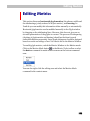
Editing Metrics
If you want to create a professional-looking font you have to edit the font’s
metric data. The glyphs’ widths, sidebearings, and kerning can be edited in
FontLab Studio automatically or manually. This chapter shows you how.
Actions
From scale to drop shadow, from autohinting to autospacing - more than
25 transformation filters can help you instantly expand your font
collection. This chapter gives detailed descriptions of all the actions and
their usage in FontLab Studio.
Hinting
To make your Type 1 or TrueType fonts look great everywhere you have to
set hints. FontLab Studio includes hinting tools that were previously
available only in high-end proprietary font editing systems. Hinting can be
a complicated process, so read this chapter carefully to get the best results.
Multiple Master Fonts
Opening, editing and exporting Multiple Master fonts; adding and
removing design axes; editing the Design Map Graph – everything you ever
wanted to know about multiple master fonts is in this chapter.
OpenType Fonts
This chapter covers FontLab Studio tools, panels and features that deal
with creation and editing of OpenType font features: ligatures, small caps,
fractions, alternative glyphs, etc.
Macro Programming
This chapter includes a short description and demonstration of the Python
programming language and its integration into the FontLab Studio user
interface. Python can be used to create custom tools and operations within
FontLab Studio. A brief description of the FontLab Studio classes exported
to Python is provided.
22
Introduction
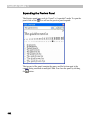
System Requirements
The Windows version of FontLab Studio requires one of the following
hardware and software configurations:
A PC computer capable of running one of the following versions of
Windows: Windows 98, Windows ME, Windows NT 4.0, Windows 2000 or
Windows XP with one of these operating systems installed.
At least 10Mb of free space on the hard disk drive and at least 64 MB RAM.
FontLab Studio will start on 32 MB RAM but you will need more RAM to
open bigger fonts.
23
FontLab Studio
User Interface
Before we start talking about fonts and the FontLab Studio font-editing
features let’s spend some time learning the FontLab Studio user interface.
For the most part it is a standard Windows interface so if you know how to
navigate in Windows or in Microsoft Office you will feel comfortable with
FontLab Studio. In other parts it is unique and that is where we will focus.
Most of the interface elements in FontLab Studio 5 are completely
customizable and from this chapter you will learn how to change the
FontLab Studio interface so it will best fit your needs.
Please note that further in the book we will refer to menu commands,
toolbar buttons and keyboard shortcuts as they appear in the default
FontLab Studio environment, prior to any modifications you may make.
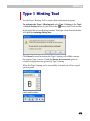
1
FontLab Studio 5
Basic Terms
We cannot go any further without defining a few terms that are critical to
understanding FontLab Studio and fonts in general.
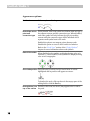
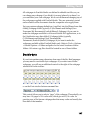
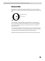
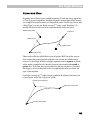
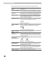
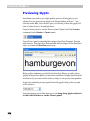
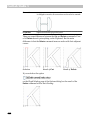
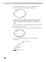
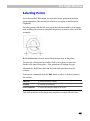
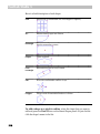
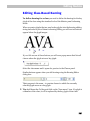
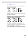
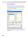
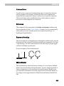
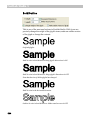
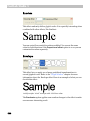
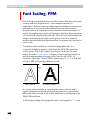
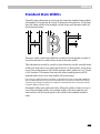
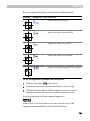
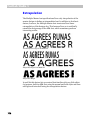
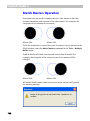
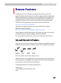
Character
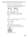
The minimal unit of the written language – a part of the alphabet, a
symbol.
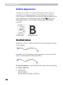
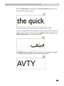
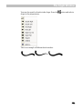
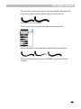
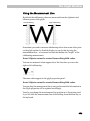
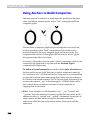
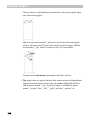
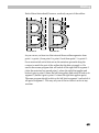
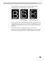
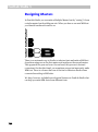
Any picture that can be recognized as having the same meaning represents
the same character:
All the pictures above mean the character ‘A’
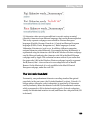
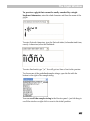
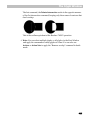
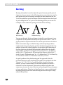
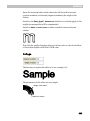
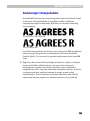
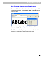
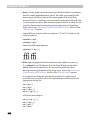
Please note that sometimes pictures that look the same represent different
characters:
Latin ‘A’
Cyrillic ‘A’
Greek ‘Alpha’
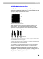
Characters have codes that are used to store text data on a computer.
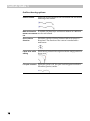
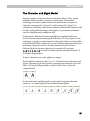
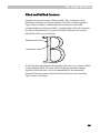
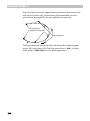
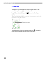
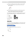
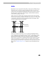
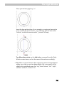
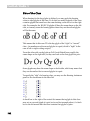
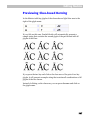
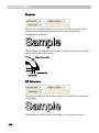
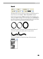
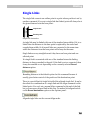
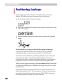
Glyph
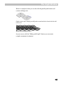
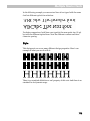
The basic element of the font, literally – an image that is printed. All glyphs
are unique, even if they represent the same character.
Glyphs are used to represent characters. Please note that many different
glyphs may be used to represent the same character, even in the same font:
26
User Interface
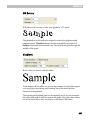
Font
An organized collection of glyphs and font header information. Usually
glyphs that are united in a font have some similarities in design and other
properties.
In the past, a “font” was defined as a single size of the characters of a
particular typeface. Now, since fonts are scalable, the term “font” covers all
possible sizes of the same typeface design.
Encoding
When text is printed an important process takes place: character to glyph
mapping. The source text (in computer form) is a list of codes that
represents a list of characters. A font (see above) is a collection of glyphs.
So there must be some way to relate characters to glyphs so that when the
computer’s operating system encounters a certain character it knows which
glyph to print. This “mapping” (or “vector”) is called the encoding.
Sometimes the encoding information resides within the font itself as part
of the header and other times it is in a separate file.
Font Family
It is important to know the difference between a font and a font family. A
font family is a set of fonts that represents some design idea. “Times” is a
font family (sometimes called typeface). “Times Bold Italic” is a font.
A font family may include from one to a few dozen fonts.
27
FontLab Studio 5
Glyph name
The only identification of a glyph (other than its visual appearance) is its
name. A Western glyph name consists of Latin characters, digits and
punctuation. It is highly recommended you name glyphs in accordance
with the following rules:
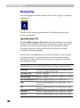
1.
No spaces.
2.
No digits at the beginning.
3.
Only ‘.’ And ‘_’ punctuation marks are allowed in the name.
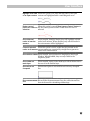
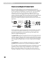
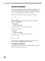
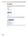
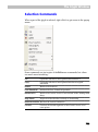
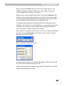
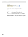
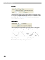
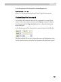
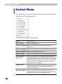
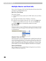
Menu
When we refer to menu items in the main FontLab Studio menu, we will
use the following notation:
[top menu item] > [sub-item]
For example:
Edit > Copy means: click the word Edit on the menu bar and select the
Copy command from the menu:
28
User Interface
Folders and Paths
Recent applications from Fontlab Ltd. use a new folder structure for
storing their data files such as encoding or codepage definitions, glyph
generation recipes, text samples for metrics and kerning, mapping tables,
Python macros etc. FontLab Studio 5 looks for data files in four different
folders.
Shared default data folder
typically, C:\Program Files\Common Files\FontLab
This folder holds files that are commonly used by all recent Fontlab Ltd.
applications: FontLab Studio 5, TransType SE/Pro, FogLamp, SigMaker 2,
with more to come. In each respective subfolder, codepage definitions,
encoding definitions, glyph-to-Unicode mapping files and some special
data files are stored. Only Fontlab Ltd. applications and applications from
registered Fontlab Ltd. developer partners should place their files there.
This is to rule out conflicts between the user’s customized files and default
files.
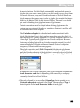
Shared user data folder
typically
C:\Documents and Settings\Your Username\My Documents\FontLab\Shared
This folder has exactly the same structure as the folder discussed above
and can store any files customized by the user. Any file placed in the
respective location within that folder will override the corresponding file
placed in the shared Fontlab Ltd. Please put your customized files in this
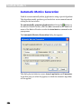
folder. The location of the folder can be modified in Tools > Options >
General Options > Folders and paths:
Application default data folder
typically C:\Program Files\FontLab\Studio5
29
FontLab Studio 5
This folder holds files that are only used by FontLab Studio 5. In each
respective subfolder, metrics, kerning and other text strings, additional
encodings, Python macros and modules as well as samples are stored. Only
Fontlab Ltd. applications and applications from registered Fontlab Ltd.
developer partners should place their files there. This is to rule out
conflicts between the user’s customized files and default files.
Application user data folder
typically
C:\Documents and Settings\Your Username\My Documents\FontLab\Studio5
This folder has exactly the same structure as the folder discussed above
and can store any files customized by the user. Any file placed in the
respective location within that folder will override the corresponding file
placed in the shared Fontlab Ltd. Please put your customized files in this
folder. The location of the folder can be modified in Tools > Options >
General Options > Folders and paths:
Please refer to the "Macro Programming" chapter for information about
placing macros and modules in the appropriate folders.
When we refer to one of the folders, we will use the following syntax:
[main folder]/[subfolder name]
Where [main folder] can be one of the following: [Shared default data folder],
[Shared user data folder], [Application default data folder], [Application user
data folder], and [subfolder name] is the name of the particular subfolder
within that folder.
For reasons of brevity, we will sometimes write:
[Shared] which will mean either [Shared default data folder] or [Shared user
data folder]
[Application] which will mean either [Application default data folder] or
[Application user data folder]
30
User Interface
This means that a particular file can be stored in either of the two locations
(default or user). Remember that user locations always override default
locations.
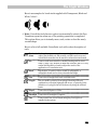
Mouse
Click the mouse on some Position the mouse cursor on the object and click the
object
left mouse button
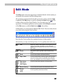
Right-click some object
Position the cursor on the object and click the right
mouse button
Ctrl-click something
Position the cursor over “something”, hold down the
CTRL key on the keyboard and click the left mouse
button.
Drag some object
Position the cursor on the object, press the left mouse
button and move the mouse to move the object.
Release the mouse button when you’re done.
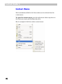
Context Menu
Most windows and panels in FontLab Studio have attached context menus.
To open the context menu, right-click an empty area in the window or
panel.
31
FontLab Studio 5
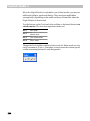
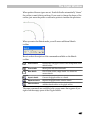
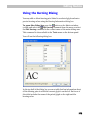
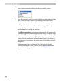
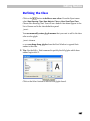
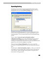
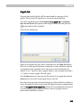
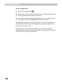
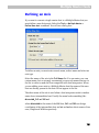
Getting Started
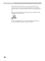
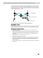
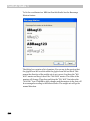
When you run FontLab Studio 5 for the first time (to run FontLab Studio
double-click on its icon
) you will see a welcome screen for a few
seconds and then the FontLab Studio window:
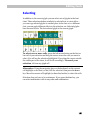
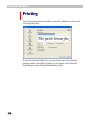
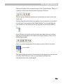
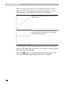
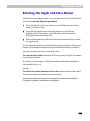
Like almost all Windows programs FontLab Studio has a menu, a few
toolbars and a status bar at the bottom.
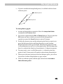
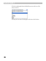
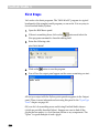
There is nothing special about the FontLab Studio menu except that you
can position it any place on the screen. The usual location is at the top of
the screen, but if you want to put it somewhere else, just drag it there:
The same thing can be done with any toolbar – you can leave them at the
top or drag them anywhere.
32
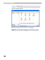
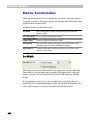
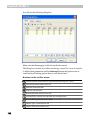
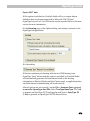
User Interface
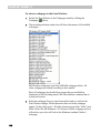
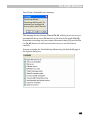
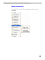
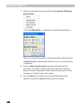
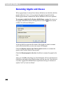
You can easily choose which toolbars you want to see: use the Toolbars
command in the View menu or simply click the right mouse button on a
menu, toolbar, or toolbar docking panel and you’ll get exactly the same
menu:
Following is a list of common toolbars with a few comments about each:
Status Bar
Status bar at the bottom of the window
Standard
Contains basic commands like file open and save, copy/paste, print
and help
Panels
Controls the appearance of FontLab Studio panels – shared
windows used to control most professional FontLab Studio features
Show Layers
Controls the appearance of basic Editing layers
Tools
Probably the most important toolbar – gives access to editing tools
that you will use to work on glyph shapes
Macro
Opens the Macro panel which gives quick access to pre-written
macro programs that can automate various font-editing tasks.
You may notice a few italic terms. We will describe them later. Specifically,
panels and Glyph window will be described in a few pages; Editing layers
in the “Glyph Window” chapter; and macro programs in “Macro
Programming” chapter.
OK, we are almost ready to open a sample font, but before we do let’s talk
about customization of the FontLab Studio user interface.
33
FontLab Studio 5
Customizing FontLab Studio’s
User Interface
As you may infer from the title of this section most of the FontLab Studio
user interface (which means menus, toolbars and keyboard shortcuts) is
customizable. We believe our default interface is the easiest to use, but if
for some reason you don’t like it, you are free to make any changes you
want. If you don’t want to change anything in the FontLab Studio user
interface, you can fast forward to the next section.
The general idea of customization is simple: there is a long list of
commands that you can use and three kinds of controls: menus, toolbars
and keyboard shortcuts. Through customization you can assign any
command to a menu item, button on a toolbar or combination of keys
pressed on a keyboard. In addition you can organize commands in popup
menus or toolbars.
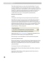
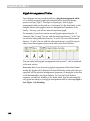
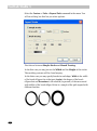
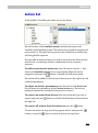
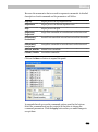
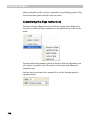
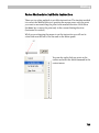
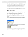
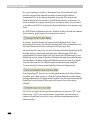
Most of the customization commands are concentrated in the Customize
panel that you can open with the Customize command from the Tools
menu or the same command located in the context menu which appears if
you right-click on a menu, toolbar or toolbar dock area:
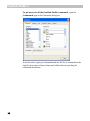
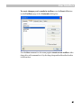
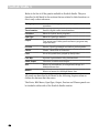
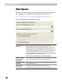
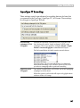
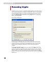
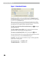
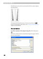
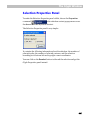
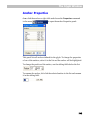
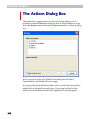
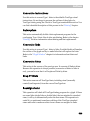
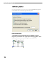
The Customize dialog box consists of several pages:
Commands
List of all the available commands grouped into several categories
Toolbars
Customization of toolbars. There is an option to create new toolbars.
Tools
On this page you can “connect” an external program to a menu item
in FontLab Studio’s Tools menu
Keyboard
Customization of keyboard shortcuts
Menu
Customization of menus
While the Customize dialog box is open all interface elements are in
“editable” mode, so you can simply drag-drop buttons and menu items
between different toolbars. You can also customize the appearance of menu
items and toolbar buttons.
34
User Interface
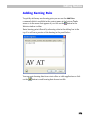
Customizing Toolbars
To move a button within a toolbar just press the left mouse button on
it; drag it to the new location and drop it. If you drag the button slightly
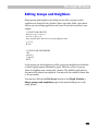
further to the right, a separator bar will be added between it and the
previous button:
To move a button to another toolbar, just drag-drop it there. To copy
a button, hold the CTRL key while you drag the button.
To remove a button from a toolbar, drag it out of the toolbar:
In FontLab Studio there is very little difference between a menu and a
toolbar, so you can re-arrange, copy or remove menu items just like
you did with toolbar buttons:
You can also drag a menu item onto a toolbar to add a toolbar button.
Hold the CTRL key to copy the item.
35
FontLab Studio 5
To get access to all the FontLab Studio commands, open the
Commands page in the Customize dialog box:
In the list select a group of commands and use the list of commands in the
right list as a source of menu items and toolbar buttons: just drag the
commands from there.
36
User Interface
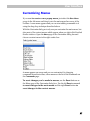
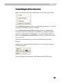
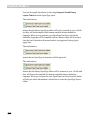
Customizing Menus
If you want to create a new popup menu, just select the New Menu
group in the left menu and drag it onto the main menu bar or any of the
toolbars. A new menu appears and you can start adding commands to it
using the drag-drop technique described above.
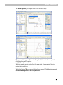
With the Customize dialog not only can you customize the main menu, but
also most of the context menus which appear when you right-click FontLab
Studio windows. Open the Menu page in the Customize dialog box and
choose a context menu in the right combo box:
A menu appears on screen and you can customize it by dragging
commands from the toolbar, other menus or the list of the commands on
the Commands page.
To reset changes you’ve made in menus, use the Reset buttons on
the Menu page of the Customize dialog box. Use the left Reset command
to reset changes in the main menu and the right Reset button to
reset changes in the context menus.
37
FontLab Studio 5
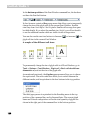
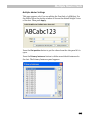
Customizing Individual Items
You can customize the appearance of any menu item or toolbar button. The
following appearances are available for most items:
Image
Text
Image and Text
To change the appearance of the menu item or toolbar button
position the mouse cursor on the button and click the right mouse button.
Select the new appearance method in the context menu:
Most commands in FontLab Studio have pre-designed images, but you can
easily create your own images for any toolbar button or menu command.
To do so, select the Button Appearance command in the button’s context
menu:
38
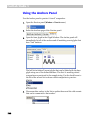
User Interface
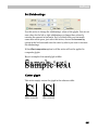
You will see a dialog box where you can choose the appearance method
and, if it includes an image, choose the picture that appears on the button
or at the left of the menu item:
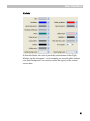
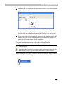
Choose a User-defined image; click New to create a new image; or Edit
to edit one of the User images. If you decide to change the picture, use
the included image editor to change it:
Use one of the Tools to edit the enlarged image and choose a color in
the Colors area. Click the OK button when you are ready.
39
FontLab Studio 5
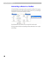
Converting a Menu to a Toolbar
In FontLab Studio some menus can be converted to toolbars. If you open a
popup menu and can see a tiny caption in the top area of it, you can drag it
to any place on screen and it becomes a toolbar:
Not all menus have this feature, but you may find it really useful.
OK, that’s almost all about customizing toolbars and menus. Just a couple
more things:
40
User Interface
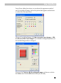
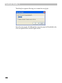
To reset changes you’ve made in toolbars, use the Reset All button
on the Toolbars page in the Customize dialog box:
Use the New command on the same page to create a new toolbar. After
doing this, add commands to it by the drag-drop method described earlier
in this section.
41
FontLab Studio 5
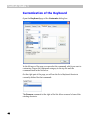
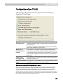
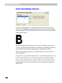
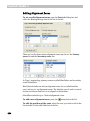
Customization of the Keyboard
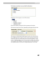
Open the Keyboard page of the Customize dialog box:
In the left area of the page you can select the command, which you want to
customize. Choose the commands category in the top list and the
command itself in the list below.
On the right part of the page you will see the list of keyboard shortcuts
currently defined for that command:
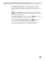
The Remove command at the right of the list allows removal of one of the
existing shortcuts.
42
User Interface
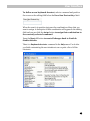
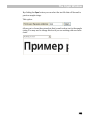
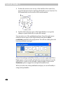
To define a new keyboard shortcut, select a command and position
the cursor on the editing field below the Press New Shortcut Key: label:
When the caret is in position just press the combination of keys that you
want to assign. A description of that combination will appear in the editing
field and you can click the Assign button to assign that combination to
the currently selected command.
Press the Reset All button to reset all changes back to FontLab
Studio defaults.
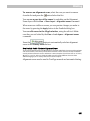
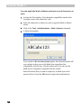
There is a Keyboard shortcuts command in the Help menu. Use it after
you finish customizing the user interface to see or print a list of all the
shortcuts:
43
FontLab Studio 5
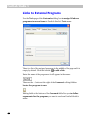
Links to External Programs
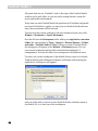
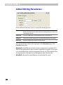
Use the Tools page of the Customize dialog box to assign Windows
programs to menu items in FontLab Studio’s Tools menu:
There is a list of the assigned programs in the middle of the page and it is
empty by default. Click this button:
to add a link.
Enter the name of the program as it will appear in the menu:
Then use the … button at the right of the Command: editing field to
locate the program to run:
Editing fields at the bottom of the Command field allow you to define
arguments for the program you want to run from FontLab Studio’s
menu.
44
User Interface
Use the button at the top of the Tools list to remove the reference to
the program and the and buttons to change the order of the
commands.
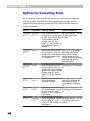
You may use special parameters to run external programs with the
currently opened font as an argument. When FontLab Studio recognizes
this argument, it will replace it with the file name of the currently active
font or with some other parameters.
Suppose that current font was last saved into file named
“c:/fonts/sample.vfb”.
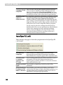
Special arguments are:
%p
Full file name of the current font [c:/fonts/sample.vfb]
%f
Name of the file with extension [sample.vfb]
%n
File name only [sample]
%x
File name extension [vfb]
%d
Path where file was saved [c:/fonts/]
%a
Path to FontLab Studio installation [usually it is “/program
files/FontLab/Studio5”]
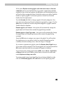
Now you know everything about the customization of menus, toolbars and
the keyboard, so you can click the Close button at the bottom of the
Customize dialog box to exit the customization mode.
Important note: in the following manual we will describe all commands,
buttons and keyboard shortcuts as they come with FontLab Studio,
without any customizations. If you changed the interface but want to
follow the manual, reset all changes with the Reset buttons on the
Toolbars, Keyboard and Menu pages of the Customize dialog box.
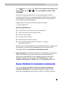
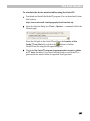
Faster Method to Customize Commands
You can customize toolbars and menus without opening the
Customize dialog box by pressing and holding the ALT key on the
keyboard and dragging buttons between toolbars or toolbars and menu.
45
FontLab Studio 5
FontLab Studio Windows
There are only three types of Windows in FontLab Studio:
Font Window
Represents one of the opened fonts
Glyph Window
Used to edit glyphs
Metrics Window
Used to edit glyph metrics and kerning.
In this chapter we will provide only very basic information about the main
windows. Please refer to the “Editing Fonts”, “Glyph Window” and “Editing
Metrics” chapters to get detailed information about the windows and their
features.
46
User Interface
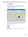
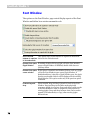
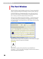
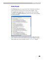
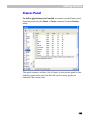
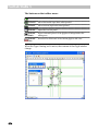
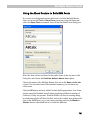
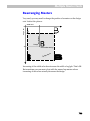
Font Window
As an exercise let's create a font in order to demonstrate the FontLab
Studio Windows. Use the New command in the File menu or click this
button
on the Standard toolbar.
You will see the Font window:
As you can see, this window has a caption with a few buttons and options
and a big table of cells that represent characters and glyphs. Each cell has a
caption that contains glyph identification information: name, Unicode
index or some other data:
Cells can also contain little icons that show properties of glyphs, but more
about that later.
47
FontLab Studio 5
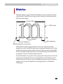
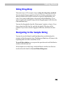
There are no glyphs in the font that we just created, but the Font window
nevertheless shows some pictures in the glyph cells. These are template
images that show which character should be placed in the cell. FontLab
Studio has templates for thousands of characters, so you will usually know
where to place new characters.
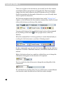
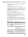
We’ll discuss navigation in the Font window later, in the “Editing Fonts”
chapter, so let’s talk about the Font window command bar, which is located
either at the bottom or at the top of the window:
You can switch between the top and the bottom location of the command
in the top-right corner of the Font
bar by clicking on this button
Window.
When the command bar is in the top position, it can be detached and you
can drag it to the bottom area or just leave it floating around:
On the command bar you can easily find a button
on the left, which is a
duplicate of the File > Font Info command, which is described later in this
manual.
Right of the buttons there is a combo box, which allows you to change the
information that appears in the character cell’s captions:
Next is a combo box that allows you to change the encoding table of the
current font:
We will talk about encodings later, but you could choose a couple different
ones from the combo box and see how the Font window changes.
48
User Interface
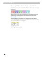
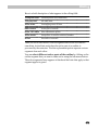
At the right of the encoding list there are four buttons that allow a choice of
encoding modes. Again, a detailed description of this follows. Just a few
words here: any glyph in the font may be identified by a name, Unicode
index or just its order in the glyph table.
Four buttons in the command bar in the top position allow you to choose
one of four modes: Names, Unicode Ranges, Codepages or Index.
In the bottom position, there is a combo box that you can use to choose the
mode:
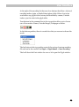
The last button in the top position controls the saving of custom encoding
file and can be also reached via Glyph > Glyph Names > Save Encoding.
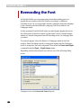
That’s all about the Font window for now so let’s open the Glyph window.
49
FontLab Studio 5
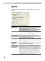
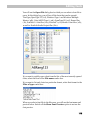
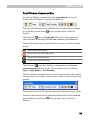
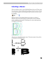
Glyph Window
To open a Glyph window for editing individual glyphs you need to
create one. Remember, we started with a new font that doesn’t have any
glyphs. To create a glyph, double-click on any cell in the Font window.
You will see that the gray cell (which means there is no glyph defined) is
replaced by a white one, which represents a glyph that is defined, but
contains no image. When you draw or paste something into it, the white
cell will show a small picture of the glyph.
After the glyph cell is created we are ready to open the Glyph window.
Select the glyph cell (just click on it with the left button) and double-click it
to open the Glyph window. It will immediately appear on screen:
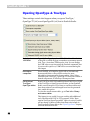
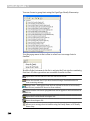
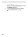
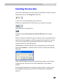
Instead of double-clicking, you can also use several other methods to
open the Glyph window:
50
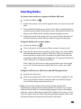
1.
Right-click the glyph cell and select the Edit command in the context
menu.
2.
Select the glyph and choose New Edit window in the Window menu.
3.
Select the glyph and press
4.
And finally, select the glyph cell and just press the ENTER key on the
keyboard.
on the Panels toolbar
User Interface
If you have more than one glyph in your font (which is normal when you
open an existing font) and have a glyph window already open when you
double-click another glyph in the Font window (or use any other method of
opening a glyph window except the New Edit window command or a
button on the toolbar) a new glyph will appear in the original glyph
window. If you need to open many glyph windows simultaneously just hold
down the CTRL key when you double-click the new glyph cell or otherwise
open a new Glyph window.
You may have as many open glyph windows as you want, just close those
you don’t need so as not have all your workspace covered with glyph
windows.
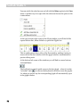
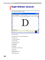
Glyph Window Contents
All windows in FontLab Studio have a similar layout: control panel on the
top and main area covering most of the window. The glyph window is no
exception: the top-docked control area (which, of course, can be docked to
the bottom location also) contains zoom, selection tools, a combo box, and
a few toolbar buttons:
Actually there are two toolbars here: the left one is used only to select the
zoom mode of the Glyph window and to choose the Zoom in and Zoom out
commands. The second toolbar is there to select the properties of the
editing tool:
To get more screen space for the editing field you may hide the zoom
toolbar if you click on this button in the top-right area of the glyph
window:
The main area of the window has scroll bars to change the view of the
glyph, and vertical and horizontal ruler bars.
51
FontLab Studio 5
You can switch the ruler bars on and off with the Rulers option in the View
menu. A quicker way is to right-click the ruler and choose the option in the
context menu:
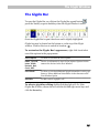
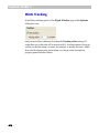
At the very bottom-right corner of the Glyph window you will find a little
expand button that, when clicked on, opens the Glyphs bar:
This is nothing more than a slice of the Font window, making it easier to
access cells in the font window while the glyph window is maximized for
precise editing work.
At the bottom-left corner of the windows you will find two more buttons,
Lock and Meter:
The Lock button controls quick access to the font glyph – when it is in the
“unlocked” state
you can use the keyboard to directly access the glyphs.
I.e. when you press a key the corresponding glyph will automatically open
in the glyph window.
52
User Interface
The Meter button
controls the appearance of the Meter panel, which
usually sits at the right end of the glyph window toolbar and shows the
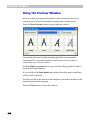
current coordinates and other parameters of the cursor:
To the right of the meter button you will find a zoom selection menu:
If you click on it you will get the zoom menu that has same options that you
may find in the zoom toolbar. This menu is useful if zoom toolbar is not
visible.
We will return to a more detailed description of the glyph window
properties in the “Glyph Window” chapter.
Finally, let’s quickly preview the last window in FontLab Studio: the
Metrics window.
53
FontLab Studio 5
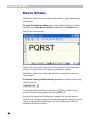
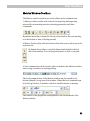
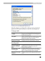
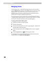
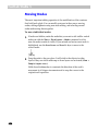
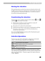
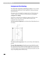
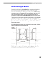
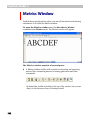
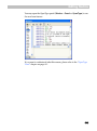
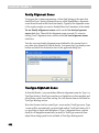
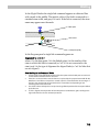
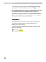
Metrics Window
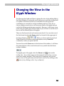
The Metrics window is used to adjust glyph metrics – glyph sidebearings
and kerning.
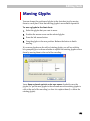
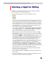
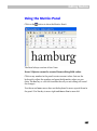
To open the Metrics window select some glyphs in the Font window
and click on the New Metrics Window command in the Window menu.
You will see a new window:
Glyphs that are currently selected in the Font window or the glyph that is
in the active glyph window will appear in the Metrics window.
The Metrics window has a main editing field, a command area and two
local toolbars.
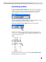
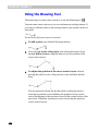
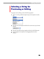
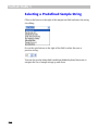
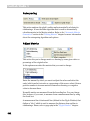
To choose a string of characters to preview or modify use the string
selection control:
button. Click it to get
To the right of the button there is an options
access to the list of strings where you can customize it.
One powerful option in this dialog box is support for a second preview
string. The second string appears below the main preview string and can be
used to compare different characters. The second string is not directly
editable in the Metrics window.
54
User Interface
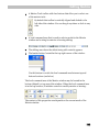
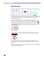
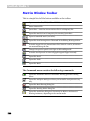
Metrics Window Toolbars
The Metrics window contains two local toolbars and a command area.
A Metrics window toolbar with controls for importing and exporting
metrics files, automating metrics or kerning generation and other
commands:
By default the toolbar is docked to the top of the window, but you can drag
it to the bottom or leave it floating around.
A Metrics Tools toolbar with four buttons that allow you to select one of the
metrics tools:
By default this toolbar is vertically aligned and docked to the left
side of the window. You can drag it anywhere or dock to any side.
A local command area that is used to select a mode for the Metrics window
and a string for metrics or kerning editing:
The local command area of the Metrics window may be located in the
bottom (default) or top area of the window. When the local command area
is in the top location, it includes controls to modify metrics or kerning:
The content of this properties area depends on the current mode of the
Metrics window.
55
FontLab Studio 5
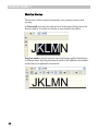
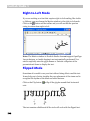
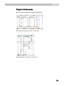
Metrics Modes
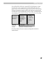
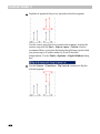
The metrics window works in four modes: text, preview, metrics and
kerning.
In Text mode you can enter and edit text in the main editing area of the
Metrics window. It works very similar to any standard text editor:
Preview mode is used to preview text with kerning applied and check it
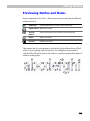
at different sizes. Also the position and width of the underline and middlestroke line can be adjusted in this mode:
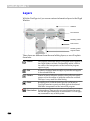
56
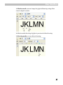
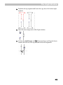
User Interface
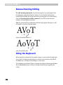
In Metrics mode you can change the glyph sidebearings using either
visual or digital controls:
In Metrics mode the string of glyphs is previewed without kerning.
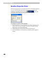
In Kerning mode you can edit pair kerning:
57
FontLab Studio 5
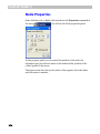
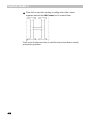
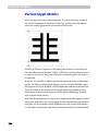
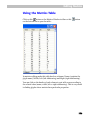
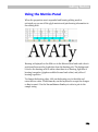
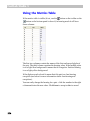
Metrics Panel
The Metrics Panel is a horizontally oriented table that may appear above or
below the editing area:
You may control the appearance of the Metrics Panel using the Panel
command in the Options local menu (when the local command area is at
the bottom) or with the Panel button on the Metrics window toolbar: .
Click on this button in the top-right area of the panel to move it
top or bottom:
When the Metrics Panel is visible, the properties area of the command area
(if it is at the top) disappears.
58
User Interface
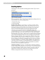
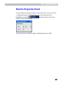
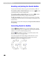
Panels
Some FontLab Studio operations are accessible through Panels – small
windows that are located in front of the main Font, Glyph and Metrics
windows:
Use the Window menu or the Panels toolbar to open panels:
59
FontLab Studio 5
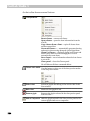
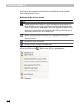
Below is the list of all the panels available in FontLab Studio. They are
described in full detail in the sections that are related to their functions, so
this is only a short reference:
Editing Layers
Control of all editing layers, “show”, “snap”, “lock”
operations
Transformation
Panel for digital outline transformations
Edit Macro
Editor for Python macro programs
OpenType
Editor for OpenType features
Output
Text output panel. Other panels and macro programs may
output text here.
Preview
Preview, OpenType Sample and Anchor preview panels.
Classes
Classes - named lists of characters
Fonts
List of all opened fonts grouped by family name
Font Map
A picture representation of big Unicode fonts
Smart Shapes
Collection of outline smart shapes
Axis
Selector of intermediate (or extrapolated) design in a
Multiple Master font
Masters
Selector of master in a Multiple Master font
All panels are described in full detail in the following chapters when we
discuss the features that they serve.
The Fonts, Edit Macro, OpenType, Output, Preview and Classes panels can
be docked to either side of the FontLab Studio window.
60
User Interface
To dock a panel just drag it close to the window edge:
To prevent the panel from docking, hold down the CTRL key while
dragging the panel’s caption.
Multiple panels can be docked on the same side. Use separator lines to
adjust their positions.
With this button
you can quickly enlarge a panel. Click the button again
to return the panel to its original size.
61
FontLab Studio 5
All panels that are not “dockable” stick to the edge of the FontLab Studio
window and to each other, so you can easily arrange them to create the
most comfortable environment.
Every time you exit FontLab Studio the positions of all toolbars and panels
are stored in Windows’ registry, so when you run FontLab Studio the next
time, the environment will be restored.
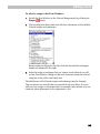
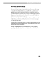
You can save the current workspace (the user interface layout) into a file:
Window > Workspace > Export Workspace
Save the file into the Workspaces folder within your Application user data
folder (the one specified in Tools > Options > General Options > Folders
and paths > FontLab Studio 5 Files). When you restart FontLab Studio,
the workspace will appear in the Window > Workspace menu. You can
save several workspaces and quickly switch between different UI
arrangements. You can also share your workspaces with different users.
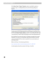
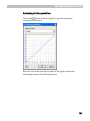
To reset your current workspace to the default (factory) state or to launch
FontLab Studio with a different workspace, hold CTRL while starting the
application. A dialog box will appear:
and you will be able to choose to start FontLab Studio with the current or
the default UI, or to load one of the workspaces.
62
User Interface
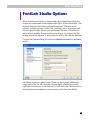
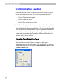
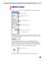
FontLab Studio Options
Most of the features, behavior, import and export algorithms of FontLab
Studio are customizable in the Options dialog box. In FontLab Studio 5 the
Options dialog box has been significantly expanded. There are more
options, so there are more choices. We encourage you to experiment with
the settings and adapt them to your preferences. However, note that the
authors have carefully chosen the factory settings so if you don’t feel like
poking around the Options, in most cases you will be fine with the defaults.
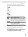
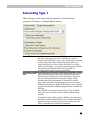
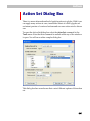
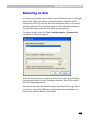
To open the Options dialog box, select the Options command in the Tools
menu:
The dialog structure is quite simple. There is a list of pages combined in
categories on the left, the contents of the currently selected page on the
right and some buttons on the bottom. You will notice that the structure of
this dialog bears resemblance to the structure of the Font Info dialog.
63
FontLab Studio 5
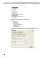
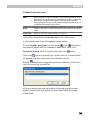
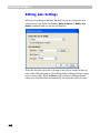
To select a page use the list on the left:
Expand one of the categories to see all the pages:
Select a page and you will see its contents appear at the right of the list:
You can browse pages continuously by clicking on
64
buttons.
User Interface
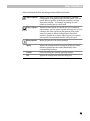
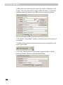
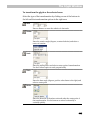
Other buttons and their meaning are described in the table:
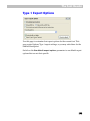
Import options
Allows you to select a profile file that holds a particular
configuration of all options and loads that profile. You can
create different profiles for different occasions and load
them when needed – for example, separately for each
format or foundry that you work with
Export options
Exports current options to a profile file. In a workgroup
environment, you can export a profile file and give it to your
colleague who then can load it and generate fonts in the
same environment. When sending technical problem
reports to Fontlab Ltd., please always export your options
into a profile file and attach that file with your report
Reset options
Resets all options to the factory defaults
Apply
Applies the changes without closing the dialog box. Many
interface changes become visible immediately in the
corresponding windows
Cancel
Closes the dialog box without applying changes
OK
Applies the changes and closes the dialog box.
65
FontLab Studio 5
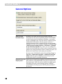
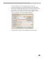
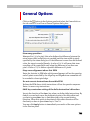
General Options
Allow to enter
Unicode strings…
Normally, you cannot directly type extended Unicode
characters into the various text fields within FontLab Studio,
e.g. the Preview panel or the Metrics Window – you need to
use the /glyphname and \Unicode notation. With this option
enabled, you will be able to directly enter the subset of
extended characters that is supported by the current system
codepage. You can set your system codepage in Control Panel
> Regional and Language Options > Advanced > Language
for non-Unicode programs. E.g. when you are working on a
Cyrillic font and would like to enter Cyrillic characters directly
instead of the slash/backslash notation, enable this option, set
Russian in Control Panel, and restart your machine.
You may want to disable this option when making changes to
Font Info > Names and Copyright > Additional OpenType
names. With this option disabled, you will always see the
hexadecimal codes for extended characters
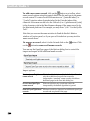
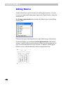
Automatically open Python macros, OpenType compilation operations and some
Output panel…
other elements of FontLab Studio write out text outputs into
the Output panel. With the option enabled, the Output panel
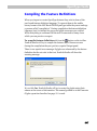
will appear every time a new message appears. With the
option disables, the Output panel will stay always hidden if
you close it
66
User Interface
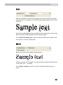
Sample text…
The font previews in the Open and Generate dialog boxes use
the string specified here to preview the font
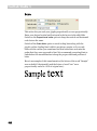
Font used in Python Allows you to choose a custom font for use in the Edit Macro
and OpenType
panel and the OpenType panel
editors
Output panel font
Allows you to choose a custom font for use in the Output
panel.
Folders and Paths
Please refer to the "FontLab User Interface" chapter for information about
these settings.
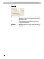
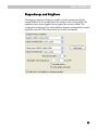
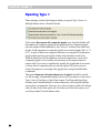
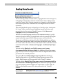
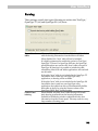
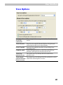
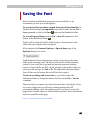
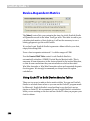
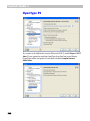
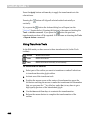
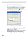
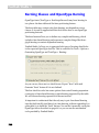
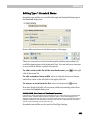
Open and Save
If you want to protect yourself from system or program crashes you can use
the Autosave function that will periodically save the current font.
Use the check box to activate Autosave and enter the time interval (in
minutes) at which you want to save the font. The font will be saved into the
Autosave folder (within the Application user data folder) and will be
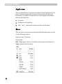
named using the following structure:
flsX.save.vfb, where fls are the first 3 letters of Font Name and the X is some
unique value.
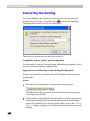
If Autosave was active and you have a system or program crash, you can
open your last saved font from the Autosave directory.
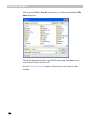
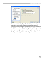
When you manually save your font and the Create backup files option is
enabled, FontLab Studio will save the previous version of your font in the
same folder as the currently saved .vfb file but will use the .bak file
extension instead. If you would like to go back and open the previous
(backup) version of your .vfb file, use File > Open, navigate to the folder in
that you saved your file and type in *.bak in the File name field, then press
ENTER. You will then see the backup file and will be able to open it.
67
FontLab Studio 5
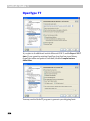
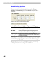
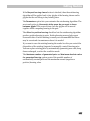
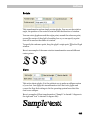
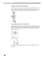
EPS and Bitmap Background
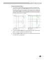
Fit EPS files to
When enabled, pasted and imported EPS/AI outlines will be
(Ascenderautomatically scaled to fit between the Ascender and
Descender) height Descender lines of the font. When disabled, pasted and
imported EPS/AI outlines will be pasted without scaling, with
the assumption that 1 pt in the EPS/AI drawing corresponds
to 1 font unit in FontLab Studio.
Bitmap height for Allows you to set the bitmap size in pixels that will be created
the Create Bitmap when the user chooses Tools > Background > Create. Higher
command
values will give you a more high-fidelity bitmap rendition of
your glyph but will result in larger .vfb files.
Tip: Tweaking this value can be useful if you want to create
pixel fonts. Set the value to a lower one, choose Tools >
Background > Create, then Tools > Mask > Swap Outline
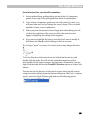
with Mask, and finally Tools > Background > Trace Pixels.
Please refer to the “Importing and Exporting Glyphs” section of the “Glyph
Window” chapter for more information about using the first option.
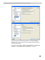
Multiple Master
With this option enabled, you can use the preview or generate MM
instances beyond the original boundaries set by the masters. If you’re
working with a Multiple Master font, choose Tools > Multiple Master >
Generate Instance and enter -200 as the instance position in the Weight
axis to generate an ultra-light variant of your font.
68
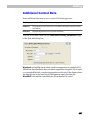
User Interface
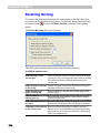
Unicode and OpenType
Add all glyph
classes to OT
feature definition
code
With this option enabled, classes defined in the Classes panel
are automatically and implicitly added to the OpenType panel
when OpenType feature definitions are compiled. Disable this
option if you defined your classes explicitly in the lower-right
portion of the OpenType panel
Do not add metrics With this option enabled when the above option is enabled,
classes
the metric classes (those with names starting with a period)
are not added to the OpenType feature definition code. The
metric classes are typically used only with the Metrics
Assistance feature and are not referenced by OpenType
features or class kerning. Disable the option if your feature
definition language references any metrics classes that you
defined in the Classes panel
Default UnicodeName mapping
table
This allows you to choose the Unicode-to-glyphname mapping
file that FontLab Studio uses to generate Unicodes based on
glyph names or vice versa. Change this if you created your
own .NAM file and prefer to use that one over the default one.
Refer to the “Generating Unicode codepoints” section of the
"Editing Fonts" chapter for details.
69
FontLab Studio 5
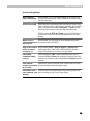
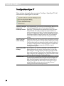
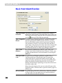
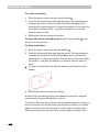
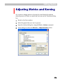
Font Window
The options on the Font Window page control display aspects of the Font
Window and define how certain commends work.
Show Unicode
This option sets Unicode indexes in captions as the default
indexes in captions choice for the Unicode mode
in Unicode mode
Double-click opens If enabled, double-click on a glyph cell in the Font Window
Glyph Window
opens a Glyph Window. If disabled, double-click does not
yield any action
Double-click opens If this option is enabled, each double-click on a cell on a glyph
a new window
cell in the Font Window opens a new Glyph Window. If
disabled and there is already a Glyph Window open, the glyph
that the user double-click on will be displayed in the existing
Glyph Window. This option works only if the previous option
is enabled
Enable drag-anddrop
70
When enabled, drag-and-drop operations work in the Font
Window. Drag-and-drop in the Index mode physically
rearranges glyphs in your font. Drag-and-drop in other modes
of the Font Window is used to assign new code positions to
existing glyphs. Drag-and-drop between fonts can be used to
append (if in Index mode) or copy (other modes) glyphs
between fonts
User Interface
Create Glyphs
This option controls what happens if the user double-clicks on
command generates an empty glyph cell in the Font Window, chooses Glyph >
Create Glyphs or Glyph > Create Glyphs If Empty. When
them if possible
disabled, the resulted glyphs will be always blank (no
outlines). If enabled, FontLab Studio will attempt to generate
a glyph. Refer to the section about Generating Glyphs for
more details
All generated
This option controls the way FontLab Studio generates
ligatures are right- ligatures if the previous option is enabled and the user doubleclicks or on an empty glyph cell that is intended for a ligature
to-left
glyph. If enabled, the ligatures generated that way will be
right-to-left, i.e. the first component of the generated ligature
will be right-most. This does not affect the way ligatures are
generated when Glyph > Generate Glyphs is called explicitly
Sorting glyphs that Controls the way glyphs are displayed in the Font Window
are out of encoding that are shown outside of the “yellow area”, that is, the glyphs
that do not belong to the currently selected encoding,
codepage or Unicode range
Only show glyph
windows from
active font
When multiple fonts are opened, the screen can quickly get
cluttered. With this option enabled, FontLab Studio will only
display Glyph Windows from the currently active font while it
will hide other open Glyph Windows. Disable this option if
you want to compare Glyph Windows from different fonts
side-by-side
Kerning information This option controls the behavior of FontLab Studio if the user
is copied with the copies any glyphs in the Font Window using the clipboard. If
enabled, all kerning pairs associated with the glyph will be
glyph
copied. If disabled, the kerning pairs will not be copied.
Disable this if you only want to copy-and-paste the glyph
shapes but not the associated kerning.
71
FontLab Studio 5
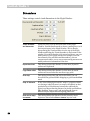
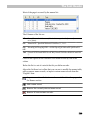
Glyph Cell
These options control the appearance details of glyph cells in the Font
Window.
Each cell should
have dimensions
of…
Controls the default size of the glyph cells in all Font
Windows. Note that when the local control area of the Font
Window is placed at the bottom, you can use the
Increase/Decrease cell size buttons to temporarily change
the size of the glyph cells in the currently active font
Give each cell a
caption
Shows/hides the caption of the glyph cell (the small
rectangular bar shown at the top each glyph cell) and allows
you to choose a font that should be used there
Show information Shows/hides the small colored information marks in the
marks in glyph cells corners of the glyph cells. Refer to the "Font Window" section
for more information about their meaning
Show note icons
Glyphs can have notes associated with them. With this option
enabled, if a glyph includes a note, a small icon will appear in
the corner of the glyph cell
Smooth glyph
thumbnails
Turns on and off the anti-aliasing of the rendered glyph
previews (thumbnails) in the glyph cells
Highlight conflicts The default Unicode-Name mapping table (see pages 69 and
between name and 91) determines the “ideal” (recommended) mapping between
Unicode index
glyph names and Unicodes. In your font, glyph names can be
mapped to other Unicodes than those recommended, or glyph
may have no Unicode codepoints assigned although they
should. With this option enabled, FontLab Studio will show
the caption background of the glyph cell in red color for all
such problematic cases. To automatically correct the problem,
use Glyph > Glyph Names > Generate Unicode.
72
User Interface
Templates
This section regards two different sorts of templates used in FontLab
Studio.
New font template: a .vfb file that can be used as basis for all new fonts
that are created in FontLab Studio. If you regularly create new fonts for the
same foundry, you can save any of your fonts as a new font template. You
may want to set an encoding, fill in the designer and vendor information
but perhaps clean font naming and all the glyphs. Later, when creating new
fonts in FontLab Studio, the new font template will be automatically
opened so all the values that are specific to your foundry are already filledin.
Glyph template images: the dark gray bitmap images that appear in
Font Window glyph cells if a glyph in the font is empty. The glyph template
images can be used as an orientation during your type design process. For
example, if you open a Western font, switch to the Unicodes mode and
choose the Cyrillic range, you will see what your Cyrillic glyphs should
roughly look like.
FontLab Studio 5 ships with a very extensive set of pre-installed default
glyph template images. These are based on the Andale Mono WTG font
(courtesy of Monotype Imaging, http://www.monotypeimaging.com/ ) and
cover the entire Unicode 3.2 character set. Note that the default glyph
template images are low-resolution, monospaced and in a “sanserif” style.
They should not be used as direct source of information about the
typographically correct shape of glyphs – but only as an orientation.
73
FontLab Studio 5
Use template font
to initialize new
fonts
When enabled, allows you to choose any .vfb file as a new font
template when the user chooses File > New. When disabled, a
blank .vfb file is created
Show glyph
When enabled, glyph template images are shown in empty
template images in glyph cells. You can also choose if the default or a custom set
of glyph template images is used. You can use any font
empty cells
installed on the system or a bitmap font file. For bitmap font
files, .bdf files are supported as well as .dat files that can be
created with BitFonter
Put glyph template When enabled, whenever you create a new glyph, the
corresponding glyph template image will be placed as a
images in
Background layer bitmap in the Background layer.
when creating new
glyphs
74
User Interface
Glyph Window
This section controls the behavior of the Glyph Window.
Editing behavior:
Show meter panel If enabled, the Meter panel is shown when the user activates
when Meter tool is the Meter tool
activated
Show crosshair
cursor
If enabled, a crosshair cursor is shown whenever the user
moves any nodes
Remove hints and When enabled, the user can remove hints and guidelines by
guides by moving moving them out of the window
out of the window
Double-click on
background to
change its
properties
When enabled, the user can double-click on the bitmap placed
on the Background layer to position or scale it. When
disabled, this is only possible via Tools > Background > Move
and Scale
Mask layer has its
own metrics
When enabled, the Mask layer has its own advance width
information. When disabled, the Mask layer always has the
advance width of the Outline layer
Selection in the
Glyph window is
undoable
While editing a glyph, the user often selects some contours or
nodes. With this option enabled, the step of selection is stored
as a separate undo step so can be undone separately from
other editing actions
Tap on Ctrl key
toggles Edit tool
When enabled, the user can press the TAB key to temporarily
enable the Edit tool if a different tool is currently active, and
press the TAB key again to revert back to that tool
75
FontLab Studio 5
Appearance options:
Small nodes
Nodes may be small or large:
Node shape shows When enabled, each node symbol will indicate both the type of
point and
the adjacent contour and the connection type. When disabled,
each node symbol will only indicate the type of preceding
connection type
contour while the connection type will be indicated with a
separate small symbol next to the node.
Enable this option to see tangent points shown as such.
Disable this option to revert to the FontLab 4.x behavior.
Refer to the “Node Type” section of the “Glyph Window”
chapter for more information about node symbols
Black/white nodes When disabled, node symbols are displayed using color as in
FontLab 3.x. When enabled, node symbols are displayed using
color as in Fontographer
Show node position One node may be selected as the current node. It will be
highlighted and its position will appear on screen:
To deselect the node, click anywhere in the empty space of the
editing field or click the ESC key
Node position is on Position of the node (see above) may appear below or above
top of the outline the path:
76
User Interface
Highlight first node When this option is on, start and end nodes of the open
of an open contour contour are highlighted with a small diagonal cross:
When this option is on and Show Layers>Control Vectors is
Bezier control
points are visible in off, the control points become visible when the curve is
selection
selected:
Show selected
nodes in inactive
masters
When enabled, Multiple Master fonts will highlight selected
nodes in all masters. When disabled, only selected nodes in
the active master will be highlighted
Connect selected When this option is active, nodes that are selected in the
nodes in all masters current master are connected by straight line segments to
nodes in all visible masters
Show anchor names When enabled, anchor names are displayed in the Glyph
Window. When disabled, they are only visible in the
Properties panel
Show nodes on
mask layer
When enabled, nodes on the mask layer will be shown even if
the user is in the Outline layer
Show arrow on
closepath
Activate this option to see small arrows on every closepath
line:
Show measurement Shows/hides the measurement line: the red horizontal line
line
that can be used for calculating sidebearings.
77
FontLab Studio 5
Outline drawing options:
Smooth outline
Allows one to select between non-anti-aliased and anti-aliased
rendering of the outline:
Mask and inactive If enabled, the Mask layer and inactive masters in a MM font
masters are smooth are also anti-aliased
too
Show contour
direction
An outline consists of several contours and each contour is
directional. The direction of the contour is marked with a
small arrow:
Leave echo while
editing
When editing contours the original contours shape/position is
shown gray:
Fill open contours When this option is off, the open contour appears unfilled in
fill outline (preview) mode:
78
User Interface
Advanced options:
Move selected
When enabled, the user can individually move nodes even if
nodes individually several nodes are selected. When disabled, all selected nodes
move the same way
All BCPs are fixed
When using non-node editing and you drag any location on a
curve, its control vectors may change direction. You can rightclick on the node and enable Connection > Fixed to fix the
direction of the control vectors for that particular node.
With the option All BCPs are fixed, you can fix the direction
of all control vectors in a font for the purposes of non-node
editing
When curve is
When enabled, you can select a curve segment and use the
selected keyboard arrow keys to move the BCPs
adjusts BCPs
Align to all contour When disabled, View > Snap to Layers > Outline makes
points if snap to
nodes snap only to other nodes. When enabled, the nodes
contour is on
snap to all locations on a contour, not just nodes
Edit/Delete
command breaks
contour
When disabled, the Edit > Cut command breaks (opens) a
contour but Edit > Delete only removes nodes but leaves the
contour closed. When enabled, both Cut and Delete break the
contour
Keep smooth
Enable this to prevent smooth node connections to turn into
connection smooth sharp connections when blending is used
at all times
VectorPaint tools
With this option FontLab Studio will provide separate set of
have separate view the view setting for the Vector Paint mode.
settings
79
FontLab Studio 5
Dimensions
These settings control visual dimensions in the Glyph Window:
80
Visual ascender
and descender
When you select 100% as the zoom value in the Glyph
Window, FontLab Studio needs to choose a scaling factor to fit
the font unit space in the Glyph Window. This is done by
always fitting the Visual ascender is to the top of the Glyph
Window and fitting the Visual descender to the bottom of the
window. If you think that the 100% zoom level shows you a too
small portion of your glyph (because for example your font
has extremely long ascenders and descenders), you can
increase these values. This is only a visual setting and does not
modify and metric information in the font
Duplicate offset
This setting controls the distance (in font units) by which
outlines are duplicated
Copy/Paste offset
This setting controls the distance (in font units) by which
outlines are moved when the user does copy-paste
Grid step
This setting controls the grid step in font units. You can
show/hide the grid and enable snapping to grid from the View
menu
Snap-to distance
If any of the editing layers has the “snap-to” property turned
on, moving a node will cause it to snap to the objects on that
particular layer if the distance between the node and the
object is not larger than the distance (in pixels) specified here.
Tip: Enabling “snap to grid” and increasing the snap-to
distance may be helpful when designing pixel fonts
Shift+arrow keys
increment
This setting defines the distance (in font units) by which
objects are moved when SHIFT+ARROW keys are used.
User Interface
Colors
In FontLab Studio, the color of practically each element of the Glyph
Window can be customized – so for example, you can edit white outlines
on a black background. You can also control the opacity of the control
vectors here.
81
FontLab Studio 5
Tracking
Hints tracking
When enabled and you move a hint by a distance less than the
Tracking offset setting, all nodes that are on the hint will be
moved with it. Use it to keep an outline on the hint when you
modify the hint’s width
Guidelines tracking When enabled and you move a guideline by a distance less
than the Tracking offset setting, all nodes that are on the
guideline will be moved with it
Track global
guidelines
82
When enabled and you move a global guideline by a distance
less than the Tracking offset setting, all nodes that are on the
global guideline will be moved with it. Note: this may affect all
glyphs in your font.
User Interface
Shape Groups and Neighbors
The shape groups layer displays a number of semi-transparent glyphs
stacked behind, or above-and-below the outline of the current glyph. The
neighbors layer shows glyphs left and right of the current outline. The
composition of shape groups and neighbors changes automatically for each
glyph that you edit. This composition can be fully customized:
83
FontLab Studio 5
Apply kerning to
neighbors
When enabled, the neighbors will be positioned taking
kerning pair values into account
Filling neighbors
These settings control when the neighbors should be filled
Mask layer view
These settings control the behavior of neighbors if the user
is in the Mask layer
Filling shape groups These settings control when the shape groups should be
filled
Edit Groups button
Click on the button to open the shape groups definition file
in a text editor (e.g. Notepad). After you finished editing the
shape groups definition file, save it in the text editor, switch
back to FontLab Studio and click on Apply in the Options
dialog box to load the new shape groups
Mask layer view
These settings control the behavior of shape groups if the
user is in the Mask layer
Shape group opacity This controls the opacity (transparency) level of the shape
groups
84
Shift glyphs in the
shape group
With the settings 0 x 0, all shapes in the shape group are
shown stacked behind the current glyph. Increase the first
value to position the shape group on the sides of the current
glyph. Increase the second value to position the shape group
above and below the current glyph
Use glyph metrics
When activated, the shapes within a shape group will be
positioned next to each other using their advance widths
Center glyphs
horizontally
When disabled, all shapes in the shape group are aligned by
their left sidebearing. When enabled, all shapes in the shape
group are centered
Double-click to edit
neighbor or shape
group glyph
When enabled, you can quickly switch between editing of
each glyph in a shape group by double-clicking on the
shapes.
User Interface
Metrics Window
These settings control the behavior of the Metrics window:
85
FontLab Studio 5
Automatic line
feed
When disabled, all glyphs in the Metrics Window are displayed
as a long line of text unless a line break is inserted explicitly by
the user (\n). When enabled, the Metrics Window has an
automatic line feed so glyphs are moved to the next line to fit
within the current size of the Metrics Window
Highlight all key
glyphs…
When enabled, all glyphs that are defined as key glyphs in the
Classes panel are highlighted
Highlight all
kerning pairs
When enabled, all glyph combinations that have kerning pairs
defined will be highlighted in the Metrics Window using a short
horizontal line below the glyphs. When disabled, the line will
not be shown
Apply text
template…
When the user clicks on a kerning pair on the Metrics Table,
FontLab Studio automatically displays a text template that
presents the kerning pair in context of other glyphs – if this
option is enabled. When disabled, FontLab Studio will not
display the additional text
Keep existing
exceptions…
If the “Class kerning” setting is active in Metrics Window and
this option is disabled, modifying a pair of dependent glyphs
that had an exception defined will remove that exception. If
enabled, the exceptions will be kept
Background
Changes the background color of the Metrics Window
Foreground
Changes the color of the glyphs displayed in the Metrics
Window
Dependant pairs
Changes the color of the glyphs displayed in the Metrics
Window that are dependant glyphs in classes
Font to use in the Customize the font to use in the preview combo box
preview combo
box
Move focus to
Disable it to preventing the text cursor jump the sample string
sample string
when Metrics window is opened
when Metrics
window is opened
Sort items in the Controls the sorting order by which the items in the Metrics
kerning/metrics Table are displayed.
table
86
User Interface
FontAudit
If you turn the FontAudit layer on in View > Show Layers, this built-in
glyph checker will on the fly detect potential errors in your glyph geometry
and highlight the problems with red arrows. These options control which
potential problems FontAudit should check against.
87
FontLab Studio 5
Empty lines and
curves
Lines or curves that have no length (I.e. two nodes on top of
each other.)
Vectors on
closepaths
Unnecessary vectors that should be removed. In Type 1 fonts
this error can cause problems with rasterization
Flat curves
Curves that can be replaced with a straight vector without loss
of quality (I.e. a “curve” that is really a straight line.)
Collinear vectors
Two sequential vectors are collinear; therefore the first vector
can be removed (Straight lines with extra nodes in the
middle.)
Inflections on
curves
Detects curves that have inflections. It is better to replace such
curves with a combination of two curves
Curve with an inflection
"Weak" extremum There are “invisible” extreme points on curves. This error can
points
cause problems with rasterization of the glyph
Curve with an invisible extreme point
"Normal"
extremum points
Curves need nodes at extreme points
Incorrect smooth
connection
A vector and curve or two curves are connected very close to a
smooth connection, but not precisely. I.e. what looks like it
should be a smooth connection is labeled as a sharp
connection.
Cusp and selfintersecting
curves
Cusp curve
88
Self-intersecting curve
Semi-horizontal
and vertical
vectors
The direction of the vector is close to vertical or horizontal but
is not parallel to one of the axes (i.e. not exactly horizontal or
vertical)
Contour is not
closed
Contour appears to be closed (visually) but is defined as open.
Use the Fix button on the error reporting dialog box to
automatically correct this situation
Object is too
short
Curve or line is short enough to be deleted.
User Interface
Optimize
These settings allow you to fine-tune the parameters of the Optimize
command (Contour > Optimize or as part of Tools > Actions).
Outline
simplification
level
The degree to which Optimize will attempt to simplify the
outline by removing nodes that are potentially redundant
Auto-alignment
level
The degree to which Optimize will attempt to align nodes for
segments that are not exactly horizontal or vertical.
89
FontLab Studio 5
Opening Type 1
These settings control what happens when you open a Type 1 font or a
Multiple Master font in FontLab Studio.
If the option Decompose all composite glyphs is on, FontLab Studio will
decompose all composite glyphs in the imported font. Composite glyphs
have no unique outline themselves, but “borrow” outlines from other font
glyphs. Good examples of composite glyphs are accented glyphs, like ‘À’, ‘å’
or ‘ñ’. In each of these the composite character is composed of a character
glyph outline and an accent glyph outline from elsewhere in the font.
FontLab Studio has all the necessary tools and operations to work with
composite glyphs, so it's usually not necessary to decompose them on
import. But if you want to significantly modify the glyphs and do not want
to worry about composites you can use this option. Of course you can
always decompose or recompose the glyphs later using FontLab Studio
commands.
The option Generate Unicode indexes for all glyphs should be usually
on. We strongly recommend keeping it that way if you plan to convert your
Type 1 font to TrueType or OpenType format. TrueType and OpenType
formats uses Unicode indexes to access characters, so having the indexes
set properly is paramount. However, if you do not plan to make a TrueType
font you may switch this option off. As in the case of the first option, you
can always make Unicode indexes later.
90
User Interface
How FontLab Makes Unicode Indexes
FontLab Studio uses a file STANDARD.NAM that is a mapping file that contains a list of PostScript
names and corresponding Unicode indexes.
When you import a Type 1 font and the option Generate Unicode indexes for all characters is on
FontLab takes the name of every imported character and looks for it in the names database. If it
locates the name there it takes the associated Unicode index and adds it to the character’s list of
indexes.
Note 1: The Names' database has more than 4000 records and includes almost all known names for
all European, Cyrillic, Arabic and Hebrew languages and for most symbol and dingbats fonts.
Note 2: The names' database is a text file that can be edited. You can add new records to this file at
any time. Be very careful when you edit this file because incorrect records may make exported fonts
unusable in some environments.
Note 3: It is possible to link more than one Unicode index to a name. If FontLab Studio finds several
indexes linked to the name, it will assign all the indexes to the character. (Refer to the Encoding
Modes section for a description of the multi-Unicode indexing method.) For glyph names preceded
with “!” in the mapping file, FontLab Studio will generate Unicode indexes based on these glyph
names but will not generate glyph names for the Unicode indexes if the user chooses Glyph > Glyph
Names > Generate Names. In that operation, only glyph names without exclamation marks are
considered.
Note 4: The default mapping file can be changed using Options > General Options > Unicode and
OpenType > Default Unicode-Name mapping table.
Generate basic
OpenType
features…
When enabled and the user opens a Type 1 font that is
encoded using the Adobe StandardEncoding, FontLab Studio
will generate a basic set of pre-defined OpenType Layout
features. This can be useful for quick conversions of Type 1
fonts into OpenType, or as a starting point for writing your
own OpenType Layout feature definitions
Find matching
encoding table if
possible
When enabled, FontLab Studio will try to match one of the
encodings available from the combo box in the Names mode
to the encoding that the font uses. If FontLab Studio cannot
match the encoding, the opened Type 1 font will show the
encoding “Imported”.
91
FontLab Studio 5
Opening OpenType & TrueType
These settings control what happens when you open a TrueType /
OpenType TT (.ttf) or an OpenType PS (.otf) font in FontLab Studio.
Scale the font to
1000 UPM
Typically TrueType fonts have UPM (Units Per eM – the size
of the grid on which all glyph coordinates are defined) equal to
2048. Type 1 fonts have UPM equal to 1000. You can change
the UPM value at any time using the FontLab commands, but
if you turn this option on, UPM will be converted during the
font import
Decompose
composites
When enabled, all composite glyphs will be automatically
decomposed. Refer to the previous section for more
information about automatic decomposition. Note: When
FontLab opens TrueType / OpenType TT fonts with rotated or
slanted components, it will always decompose them
Store custom
TrueType/
OpenType tables
Some TrueType fonts have additional tables that are not a part
of the TrueType or OpenType specification, or that FontLab
Studio cannot interpret. If you want to read these tables and
have them written in an unchanged form into the generated
font, enable this option.
To view the stored custom tables, go to Font Info > Binary
and custom tables.
This feature is very useful if you are working with additional
tools, like Microsoft VOLT or VTT programs. If the “Store
custom TrueType/OpenType tables” option is active, FontLab
will not change or destroy tables that these tools include in
TrueType fonts. Please refer to the “OpenType Fonts” chapter
for more discussion on this.
92
User Interface
Reading Name Records
All font naming (family and style names, copyright and version strings etc.)
in OpenType and TrueType fonts are stored in the “name” table. In most
cases, the “name” table contains separate sets of names for the Macintosh
and Windows platforms, sometimes also non-English names are stored
separately.
When FontLab Studio opens an OpenType or TrueType font, it interprets
the “name” table, extracts the most important names and in any case,
presents them to the user in a “friendly” manner in the Names and
Copyright section of the Font Info dialog.
However, if several language versions of the same name entry (e.g. style
name) are found in the font, FontLab Studio will only present the English
names in the Style name field. If different names are stored for the
Macintosh and Windows platform, FontLab Studio will pick one of them.
In such cases, the user may with to also store and edit the “native” form of
the “name” table. The “native” form of the “name” table can be then viewed
and edited in Font Info > Names and Copyright > Additional OpenType
names.
With the setting Read only non-English name records names
(recommended for Western fonts) the Additional OpenType names
page will only contain non-English names while the English names will be
presented in the “friendly” manner.
The setting Do not read OpenType name records discards all nonEnglish name entries so the Additional OpenType names page will be
empty. English names will be presented in the “friendly” manner.
With the setting Read all OpenType name records (recommended for
non-Western or multilingual fonts) the Additional OpenType names
page will contain all names found in the original font’s “name” table. In
addition, the English names will be also presented in the “friendly”
manner.
Read OpenType
layout tables
Please refer to the “OpenType Fonts” chapter for detailed
description of this and the subsequent options.
93
FontLab Studio 5
TrueType/OpenType TT
These settings only apply when you open a TrueType / OpenType TT (.ttf)
font but not an OpenType PS (.otf) font.
Convert TrueType In FontLab Studio, you can work with PostScript Bezier curves
curves into
or TrueType quadratic curves. If you open a TrueType /
PostScript curves OpenType TT font and plan to generate the font in the same
format, disable this option to keep the original outlines to
avoid conversion errors. But if you plan to generate your font
as a Type 1 or OpenType PS font, you can enable this option to
convert the outlines on import. In any case, you can always
convert the outlines in either direction at any time during
editing
94
Store TrueType
native hinting
Leave this option on if you want to store the original TrueType
instructions and outlines. FontLab Studio will keep the stored
TrueType data until you change the glyph’s outline or hints. If
you open a TrueType font to rearrange glyphs or to add some
new glyphs we highly recommend storing the original
TrueType hinting data
Import embedded
bitmaps
If this option is on, FontLab will Studio read all embedded
bitmaps defined for the source TrueType font. You can edit
them using the TrueType hinting tool and optionally include
them in the generated TrueType font. Embedded bitmaps may
help to improve font readability at low point sizes and in some
cases can be used instead of TrueType hinting
Autohint font
To prepare an imported TrueType font for Type 1 editing and
export, you may ask FontLab to automatically make Type 1
hints for all the glyphs. FontLab will use the current Type 1
hinting settings and will make hints for TrueType or Type 1
outlines depending on the conversion setting (Convert
TrueType curves into PostScript curves).
User Interface
Generating Type 1
These settings control some technical parameters of fonts that you
generate in the Type 1 or Multiple Master format.
Make PFM file
Switch this option on to create a PFM (Printer Font Metrics)
file when exporting a Type 1 font. PFM files are used in
Windows to install Type 1 fonts. They contain metrics, kerning
and, partially, font header information. On Windows, you
cannot install a Type 1 font without a PFM file. If you have
Adobe Type Manager 4.1, it can automatically generate a PFM
file based on an AFM and INF file but in general, we
recommend leaving this option on at all times
Make AFM and INF Switch this option on to make AFM (Adobe Font Metrics) and
files
INF (font INFormation) files when exporting a Type 1 font.
These files are text files and contain descriptions of the font
metrics, kerning and header (font names, weight, width,
encoding and other information). It is possible to install a
Type 1 font with Adobe Type Manager if you don’t have the
PFM file but do have the AFM and INF files, because ATM will
automatically build the PFM file using data from the AFM and
INF files.
The AFM file is necessary to install a Type 1 font (in ASCII
form, with “.pfa” extension) in most Unix-based operating
systems.
To install an exported Type 1 font in Windows you must have
the PFM or at least AFM+INF files. We recommend making all
these files when you finally produce a font so that your font
will be compatible with various environments.
95
FontLab Studio 5
Encoding Options
The dialog has a list of possible encoding options when a Type 1 font is
generated:
When you generate a Type 1 font, the most important encoding choice is to
choose between one of two encoding forms:
Standard Encoding
custom encoding
Standard Encoding is a special Type 1 encoding created by Adobe
Systems. Instead of enumerating all the code positions in the font, the
Standard Encoding font leaves the actual encoding to the system font
driver, and on the other hand, the system font driver knows what
characters can be expected in the font. StandardEncoding is the
recommended choice if your font is a typical Western Roman font. If you
generate a Mac Type 1 font (on FontLab Studio for Mac) with Standard
Encoding, Mac OS will “know” that the font is a standard Western Roman
font and will automatically match the font’s encoding to the system Mac
Roman codepage. Similarly, when you generate a Windows Type 1 font
with Standard Encoding, Windows will know that the font is a standard
Western Roman font and will automatically match the font’s encoding to
the system Windows 1252 Western (ANSI) codepage. Also, if the user of
such fonts create documents in some applications (e.g. QuarkXPress for
Mac and Windows), the applications will automatically re-encode the
documents when moving between platforms.
Custom encoding is any Type 1 encoding that is explicitly specified in
the font. If the primary character set of your Type 1 is not Western Roman
but Central European, Cyrillic, Greek, or Arabic, you need to select the
appropriate encoding in the Names mode encoding selector in Font
Window, and generate the font with custom encoding.
96
User Interface
How Windows ATM Interprets a StandardEncoding
When a Type 1 font has StandardEncoding ATM assumes that this font includes all the glyphs from
the first 128-glyph range (digits, alphabet and basic punctuation) and the European glyphs (128-255
range). The first 128 glyphs are called the “top zone ”. The 128-255 range is called the “bottom zone”.
The Adobe StandardEncoding includes very few glyphs from the bottom zone compared to the
number of glyphs in the WinANSI (actual Windows encoding) encoding. When a Type 1 font in
StandardEncoding is installed with ATM, ATM uses a special encoding instead of the “real”
StandardEncoding as it is documented in the Type 1 format specification. This special Windows
encoding is called the Default Encoding in FontLab. So if you create a StandardEncoding font and
want to see how it will work in Windows, select the Default Encoding in FontLab.
Here is an explanation of the possible encoding export options:
Select encoding
automatically
This is the recommended setting. Generates the font
with Standard Encoding if the Font Window is in Names
mode and the encoding selector shows one of the following:
“Adobe Standard Encoding”, “Default Encoding”, “MS
Windows 1252 Western (ANSI)” or “Mac OS Roman”.
Otherwise, a custom encoding will be generated
Always write
custom encoding
FontLab Studio will always generate a custom encoding –
even for Western Roman fonts – with the encoding
currently selected in the Font window Names mode. Note:
Western Roman Type 1 fonts generated with custom
encoding may not work as expected
Always write
Standard Encoding
Always generates the font with the Standard Encoding
regardless of what is selected in the Font window Names
mode
Export Unicode
Exports a custom encoding based on the currently selected
codepage if codepage codepage if the Font window is in Codepages mode.
mode is active
We recommend setting the Select encoding automatically option as the
default, because it covers most exporting situations very well.
Export only
encoded glyphs
When enabled, all glyphs that are outside of the encoded
“yellow area” will not be included in the generated font.
Tip: This can be used to quickly generate a series of Type 1
fonts from a large multilingual .vfb file that includes an
extensive character set.
Automatically sort This option allows FontLab to sort glyphs accordingly to the
glyphs
selected encoding on export. It is recommended to leave this
option enabled.
97
FontLab Studio 5
If the Open Type 1 Export Terminal option is switched on and you
generate a Type 1 or Multiple Master font, the following dialog box
appears:
As you can see, this dialog box previews and allows you to edit text data
contained in the “open” and “private” sections of the exporting Type 1 font
file. Use the Select a data section control to choose the part of the Type
1 font file that you want to edit and modify the text in the edit field below.
Note that there is no external control of changes you make in the export
terminal. Use it only if you really know what you are doing or you may
create a font which will not only be unusable, but can even crash your
operating system.
Refer to the Type 1 font format specification
http://partners.adobe.com/asn/developer/pdfs/tn/T1_SPEC.PDF
for information about the contents of the Type 1 font file.
98
User Interface
Use WinAscent
and WinDescent
as font vertical
size
When disabled, the Type 1 font will be generated with the
vertical metrics information based on Font Info > Metrics and
Dimensions > Key dimensions > Ascender / Descender.
When enabled, the Type 1 font will be generated with the
vertical metrics information based on Font Info > Metrics and
Dimensions > TrueType-specific metrics > WinAscent /
WinDescent. This can be used to generate a Type 1 and a
TrueType / OpenType TT font that both have identical vertical
metrics.
Note: We recommend disabling this option
Autohint unhinted When enabled, all glyphs that include no hints will be
glyphs
autohinted
Export FSType
(font embedding)
parameter
When enabled, the embedding information (Font Info >
Names and Copyright > Embedding) will be written in the
Type 1 font. Note that this is a custom extension to the Type 1
font format and is not supported by all devices so we
recommend keeping this option disabled.
Type 1 Autohinting
When this option is enabled and a glyph is autohinted, existing hints will
be removed.
When disabled, the automatically generated hints will be added to the
existing hints. Note that this may cause some unwanted interferences.
99
FontLab Studio 5
Generating OpenType & TrueType
These settings control some technical parameters of fonts that you
generate in the TrueType / OpenType TT (.ttf) or OpenType PS (.otf)
format:
Automatically
reorder glyphs
100
If this option is enabled, FontLab Studio will try to reorder
glyphs to match the Mac cmap encoding table. Technically,
this is a requirement of the Apple TrueType specification but
it is not required on Mac OS X or Windows.
User Interface
Writing Name Records
All font naming (family and style names, copyright and version strings etc.)
in OpenType and TrueType fonts are stored in the “name” table. In most
cases, the “name” table contains separate sets of names for the Macintosh
and Windows platforms, sometimes also non-English names are stored
separately.
In the Font Info dialog, naming entries are stored in the “native” form of
the OpenType “name” table (Font Info > Names and Copyright >
Additional OpenType names) as well as in a “friendly” form (all the other
sections of the Names and Copyright section of the Font Info dialog).
With the setting Do not export OpenType name records, the generated
font will obtain its naming only from the “friendly” portions of the Font
Info dialog, i.e. the Basic set of font names page, the OpenType-specific
names page, the Copyright information page etc. The Additional OpenType
names page will be ignored.
With the setting Append OpenType name records to the names
exported by default (recommended), the generated font will obtain its
naming from the “friendly” portions but the information from the
Additional OpenType names page will be appended.
With the setting Export only OpenType name records - ignore default
names, only the “native” naming defined on the Additional OpenType
names page will be written into the font and the “friendly” information will
be ignored. This is a setting suitable for complicated multilingual, esp.
Asian fonts.
101
FontLab Studio 5
Encoding Options
Ignore Unicode
indexes in the
font
When disabled (recommended), the font will be generated in
Unicode mode. The Unicode indexes assigned to the glyphs
will be used as base for the encoding.
When enabled, the encoding selected in the Names mode will
be used as source of the encoding of the generated font instead
of the Unicode indexes assigned to glyphs.
There are two possible methods of making TrueType Unicode mapping
tables. Unicode mode (This works when Ignore Unicode indexes in the
font is disabled) and Names mode (when the option is enabled).
The Unicode mode is preferred and recommended. In Unicode
mode FontLab uses the Unicode indexes that you assigned to the glyphs
while moving glyphs in the Unicode mode of the Font window or by
entering Unicode indexes in the Rename Glyph dialog box. In the Names
mode FontLab will encode all glyphs in the encoding currently selected in
the Font window (“yellow” glyphs) and put them in the first 256 range of
the TrueType Unicode table. FontLab will put all other glyphs into the
unencoded zone of the Unicode table (starting from the code E000h).
The Unicode TrueType exporting mode is usually used to export fonts that
were imported from TrueType font files and already have Unicode
information. The Names mode is useful when you convert a Type 1 font to
the TrueType format and do not want to worry about assigning Unicode
indexes.
The general rule is simple: if you work with the Font window in Names
mode use the Names TrueType exporting mode. If you work in Unicode
mode use the Unicode exporting mode. Actually, FontLab will show a
warning message if you try to export a font in Unicode mode while you are
in the Names mode of the Font window and vice versa.
102
User Interface
What is the “First 256 Glyphs Range”?
When we talk about the “first 256 glyphs” we do not mean those with Unicode indexes in the 0000h
- 00FFh range. We mean those that Windows will see as having codes 00h-FFh when the default
Windows codepage is selected. In most cases the default codepage is the 1252 Latin 1 codepage.
So even if you export a TrueType font in the Names mode the Unicode indexes for the encoded
glyph will be selected from the Windows 1252 codepage.
We recommend opening a Windows TrueType font, switching to the Codepages mode of the Font
window and selecting codepage 1252 to better understand what the “standard” Windows glyphs
are.
Windows Symbol Encoding
If you want to have full control over glyph codes and you want to occupy all 256 glyph cells of the
first-byte range, you should create your font using the Windows Symbol codepage. The Symbol
codepage begins from Unicode index F000h and continues to F0FFh. All glyphs in this range are
mapped to the 0000h-000FFh range. So the glyph with code F041h will be seen in Windows as ‘A’
and so on.
To make a font using the Symbol codepage you have two options:
1. Switch the Font window to the Codepages mode; select the Windows Symbol codepage; and
place all glyphs in the codepage. Export the font in TrueType format in Unicode mode.
2. Switch the Font window to the Names mode; select any encoding vector; place glyphs as you
want in the “yellow” area; and export the font in Names mode (Use Unicode indexes as the
base for TrueType encoding should be off).
In either case select Symbol Microsoft Glyph Set in the Codepages page of the Font Info dialog
box. Without this the font will not be exported as Symbol and you will not have access to the glyphs
at all.
The Problem of Glyph 183, “middledot”
The glyph cell with decimal code 183 has different behaviors in Windows 95 and Windows NT. In
Windows 95 it is mapped to the Unicode index 22C5h, but in Windows NT it is mapped to 00B7h. So,
when FontLab exports your font in the Names mode, it automatically assigns both Unicode indexes
to this glyph to make the font compatible with both operating systems.
Use the OpenType
names as menu
names on
Macintosh
When enabled (recommended), the family name and style
name for the Macintosh platform will be taken from the
OpenType-specific font names page rather than the Basic
set of font names page. With this setting, Mac OS applications
may group all font styles into one large font family.
When disabled, the naming defined on the Basic set of font
names page will be used as naming records for both
Macintosh and Windows
Write stored
When enabled, stored custom TrueType/OpenType tables will
be written into the generated font. To view the stored custom
custom
TrueType/OpenTy tables, go to Font Info > Binary and custom tables
pe tables
Export OpenType
layout tables
Please refer to the “OpenType Fonts” chapter for a discussion
of these settings.
103
FontLab Studio 5
Digital Signature
This section controls settings for digital signatures that can be included in
the OpenType (TT or PS) fonts that you generate. Please refer to
http://www.microsoft.com/typography/developers/dsig/default.aspx
for more information about digital signatures.
Generate digital
signature
When enabled, a DSIG table will be generated that includes an
digital signature. Note that you need to own a valid
Authenticode code signing digital certification to be able to
digitally sign fonts. You should point FontLab Studio to your
certificate file and private key file that you will receive from
your certification authority. It is a good idea to store the
private key file in a safe location, e.g. on a floppy disk or USB
key, although you can use any location.
Please refer to the link above for more information
104
Request private
key password
every time
When selected, FontLab Studio will ask you for the password
for your private key every time you generate a font
Use the following
password
When selected, FontLab Studio will remember the password
for your private key
Generate the
time stamp
When selected, a time stamp will be generated.
Please refer to the link above for more information.
User Interface
TrueType/OpenType TT (.ttf )
These settings only apply to fonts that you generate in the TrueType /
OpenType TT (.ttf) format:
Export hinted
TrueType fonts
FontLab will export TrueType instructions of any type
(original, manually edited or automatically generated) only if
this option is on.
To create a completely unhinted TrueType font switch off this
option (may be useful for pixel fonts)
Write stored
TrueType native
hinting
If this option is on and the original TrueType instructions
were stored when the font was opened, then FontLab will try
to restore the original instructions where possible. If you want
to discard all the original TrueType instructions, switch this
option off
Export visual
TrueType hints
FontLab Studio will compile the visual TrueType instructions
only if this option is on
Autohint unhinted If this option is on, FontLab will try to automatically generate
glyphs
TrueType instructions for all unhinted glyphs.
How FontLab Autohints TrueType Fonts on Export
When autohinting is allowed and FontLab finds a glyph that has no TrueType hints of any kind
(original hints imported from the TrueType font file or manually edited visual hints) it begins to
make TrueType hints automatically. If this glyph has Type 1 hinting information, then FontLab
converts this information to visual TrueType instructions and converts the instructions to the
TrueType hinting code. If Type 1 hints are not present then FontLab automatically generates Type 1
hints as the first step, then converts the Type 1 hints into TrueType visual instructions and converts
the visual instructions into TrueType native instructions.
105
FontLab Studio 5
Export embedded
bitmaps
If this option is on, FontLab Studio will export embedded
bitmaps if they are present. If you don’t want to save bitmaps
in the font, switch this option off
Copy HDMX data
from base to
composite glyph
If this option is active, FontLab Studio will copy HDMX data
(device and point-size specific font metrics) from the base
component of the composite glyph to the composite glyph if
their metrics are the same
Export "mort"
table if possible
FontLab Studio will attempt to generate the AAT “mort” table
and include it in the generated font
OS/2 table
Allows you to select the version of the “OS/2” table in the
generated font. Select table version 2 for maximum
compatibility of your font with older systems
Use CacheTT
program to
generate device
metrics tables
Please refer to section about Device-Dependent Metrics of the
“Font Header” chapter for information.
TrueType Autohinting
This section controls the way FontLab Studio performs TrueType
autohinting.
Please refer to the “Autohinting Options” section of the “Hinting” chapter
for detailed description of these options.
106
User Interface
OpenType TT Encoding
These settings control some advanced re-encoding features for fonts that
you generate in the TrueType / OpenType TT (.ttf) format. These settings
do not apply to OpenType PS fonts.
Use following
codepage for first
256 glyphs
FontLab can optionally reencode the first 256 glyphs of the
font, letting you create a “single-codepage” font for some
codepages. This is very similar to using the Glyph > Glyph
Names > Reencode glyphs command before export.
The list located below this label contains several choices:
The first option, “Do not reencode the first 256 characters”
means that reencoding is off. All other options in the list let
you select a remapping table to perform reencoding
Export only first
256 glyphs
This option is enabled only if you choose one of the remapping
codepages in the list above.
When this option is on FontLab will export only glyphs whose
codes are in the 0-255 range
107
FontLab Studio 5
Use following
codepage to build
cmap table
This is a “hack” used in older operating systems (Windows
95/98) to improve handling of single-codepage non-Latin
fonts. It is not required and not recommended, but if you
find that you need to use this hack to get your font to work in
an old OS, just switch on this option and re-export the font
Put MS Char Set
value into
fsSelection field
Encoding information is stored in TrueType and OpenType
fonts in a “cmap” table. Every Windows TrueType font
contains at least two of these tables. One is the Unicode table
and it “assigns” Unicode information to Glyphs. The other is a
single-byte table that is used by older versions of the Mac OS
and by some non-Unicode-compatible Windows programs.
Use the control to select the codepage that will be used to
build this table. There are two special options: Mac OS Roman
(which is the codepage used on the Mac and the default
choice) or Current codepage in the Font Window, which
means that FontLab will use the encoding (yellow zone)
currently selected in the Font window.
OpenType PS (.otf )
These settings only apply to fonts that you generate in the OpenType PS
(.otf) format.
Decompose all
composites
When enabled, all composite glyphs in the font will be
decomposed. Recommended for maximum compatibility.
When disabled, the composite glyphs will be exported as such
Use subroutines
to compress
outlines in the
CFF table
Allow to automatically generate outline subroutines if font is
generated as CFF-flavored. Outline subroutines store
repetitive parts of outlines and allow to reuse with references
from outline definition code
Autohint unhinted When enabled, all glyphs that contain no hints will be
glyphs
autohinted
Use the PostScript When enabled, the PostScript Font Name record will be
FontName as Full copied to the Full Name record for the Windows platform. It is
Name on Windows recommended to keep it enabled on all the time as this is a
requirement of the OpenType specification.
108
User Interface
Kerning
These settings control what types of kerning are written into TrueType /
OpenType TT (.ttf) and OpenType PS (.otf) fonts:
Export "kern"
table
When enabled, a plain “kern” table will be included in the font
with the kerning information from the Metrics Window.
When disabled, the “kern” table will not be included.
It is highly recommend to enable this option for TrueType /
OpenType TT fonts. For OpenType PS fonts, the OpenType
specification does not envision the “kern” table to be part of
OpenType PS fonts but it is possible to include the table
nonetheless. Mac OS X and Adobe applications will read and
use this table.
If the plain “kern” table is not included in the OpenType TT
font and the font is used in a non-OpenType-savvy
application, no kerning will be available.
If the plain “kern” table is not included in the OpenType PS
font and the font is used in a non-OpenType-savvy
application, the Adobe font driver will automatically build a
kern table on the fly by using the Western subset of the
OpenType GPOS “kern” feature kerning
Expand class
kerning
When enabled, the plain “kern” table kerning will include
plain kerning generated from the kerning information
available in the Metrics window combined with the class
information from the Classes panel. This may result in a very
large number of kerning pairs
109
FontLab Studio 5
Generate only
pairs with glyphs
in following
codepage
With this setting, you can subset the expanded kerning. Only
kerning pairs for glyphs included in the specified codepage
will be included in the expanded plain “kern” kerning
Limit total
number of pairs
in the table
With this setting, you can limit the number of kerning pairs
included in the expanded plain “kern” kerning table to a
certain number. The kerning pairs with lesser absolute value
will be removed until the overall number of kerning pairs is
not larger than the limit specified here
Generate "kern"
feature if it is not
defined
FontLab Studio checks if a “kern” OpenType feature is
specified in the OpenType panel. If found, the “kern” feature
will be included as GPOS OpenType kerning.
This option controls what happens if the “kern” feature is not
defined in the OpenType panel.
With this option enabled, FontLab Studio will automatically
generate the “kern” OpenType feature based on the kerning
specified in the Metrics Window and the class information
specified in the Classes panel.
With this option disabled, no “kern” feature will be written
into the font if the feature is not specified in the OpenType
panel.
110
User Interface
Trace Options
How tight a fit
should the
contour be?
This setting includes some presets for the advanced trace
options
Trace tolerance
Allows you to change the distance between the generated
outline and the edge of the original bitmap
Curve fit quality
Allows you to change the accuracy of curve fitting in the
generated outline
Straighten angle
Defines the angle between two lines less than which the
autotracer will replace several lines with one line
Tracer may
generate curves
This option (active by default) allows the autotracer to
generate curves
This option (active by default) forces the autotracer to insert
Tracer should
generate extreme nodes at the extreme points of curves.
points on curves
111
Editing Fonts
In this chapter we will discuss the editing of fonts. A font is a collection of
glyphs with similar design and some encoding and header information.
The information includes font identification names, copyright data,
character encoding information and other data that is necessary for font
usage. Generating fonts is not discussed in this chapter. Refer to the
“Generating Fonts” chapter for this information.
2
FontLab Studio 5
Opening Fonts
With FontLab Studio you can create new fonts or open existing fonts for
modification. When you open an existing font, however, please be sure that
modifying it does not violate copyright laws: some fonts are copyrighted as
software so it is not legal to change them in any font editor. Carefully read
the license agreement that comes with every font.
You can find two (one serif and one sans-serif) royalty-free, noncopyrighted fonts that you can use as a basis for your own fonts or
characters in the Sample folder or on our website
(http://www.fontlab.com/).
To open a font for editing, select the File > Open command, or click
the
button on the toolbar.
114
Editing Fonts
You will see the Open File dialog box in which you can select a font file to
open. In this dialog box, you will see all the fonts that can be opened:
TrueType/OpenType TT (.ttf), Windows Type 1 and Windows Multiple
Master (.pfb), Unix/ASCII Type 1 (.pfa), OpenType PS (.otf), Ikarus files
(.ik), FontLab 2.5 font files (.vfa), FontLab 3.x/4.x/Studio 5 font files (.vfb),
as well as FontLab Studio Project files (.flw).
If you want to quickly open a font from the list of the most recently opened
fonts, select that font in the File name combo box.
If you want to list only fonts in a particular format, select that format in the
Files of type combo box:
When you select a font file in the files area, you will see the font name and
preview below. Switch off the Show Font Preview option to not see the
font preview.
115
FontLab Studio 5
You can open many fonts with a single operation: just select all of them in
the list with a selection rectangle or using CTRL-click.
You can set the opening options here by clicking on the Options button.
Please refer to the “FontLab Studio Options” section for a detailed
discussion of the opening options.
You cannot use File > Open to open fonts located in the system font folder
(typically C:Windows\Fonts). To open any of these fonts, use File > Open
Installed. This will show a dialog box that displays all fonts installed on
your system – choose one and click on OK to open the font.
116
Editing Fonts
Most Recently Used Fonts
All fonts that you recently opened in FontLab Studio are added to the list of
the most recently used font. This list is used in the File Open dialog and
also at the bottom of the File menu:
Next time you want them, just select the font file in the File menu and
FontLab Studio will open them.
Opening Fonts with Drag-Drop
An easy way to open fonts in FontLab Studio is to drag-drop font files from
Windows Explorer onto the FontLab Studio application window:
117
FontLab Studio 5
Font Formats
The .vfb file format used in FontLab Studio 5 is fully backwardscompatible, so FontLab Studio 5 can open any .vfb file created in
FontLab 3.x and 4.x. The format is also cross-platform-compatible so
.vfb files saved from the Windows version can be opened in the Mac
version and vice versa. In addition, the format is largely upwardcompatible. This means that a .vfb file saved from FontLab Studio 5 can
be opened in FontLab 3.x or 4.x, as well as other Fontlab Ltd. products
such as TransType or TypeTool. Only those elements of the format that
were supported by the old version will be retained and some information
may change slightly. However, the most important elements of the font
such as key Font Info entries, glyph outlines and kerning pairs will be
retained.
For example, .vfb files saved from FontLab Studio 5 for Windows can be
opened in FontLab 4.6 for Macintosh and vice versa, with as much as
possible information retained.
FontLab Studio 5 also opens .vfa files saved from FontLab 2.5 (but not 2.0).
If you have fonts saved in a proprietary format of another application and
would like to open these fonts in FontLab Studio, the best way is usually to
create a Windows-compatible Type 1 font from your other application and
open the Type 1 font in FontLab Studio. If you wish to move your .fog files
created in Fontographer 3.5 or 4.1 to FontLab Studio, you can use our
FogLamp product that converts Fontographer .fog files into FontLab
Studio-compatible .vfb files, retaining not only outline information but also
mask layers, guidelines, background bitmaps etc.
118
Editing Fonts
Creating a New Font
If you want to create a new font from scratch, you select the New command
from the File menu. FontLab Studio will create an empty font that will not
have any characters and will open an empty Font Window.
You can use an existing .vfb file as a new font template for all new fonts
that are created. You can do this in Tools > Options > Font Window
>Templates:
Enable the option and select the .vfb file to use as the new font template by
button. Whenever you create a new font, the selected new
pressing the
font template will open. Remember that after the new font template opens,
you should choose File > Save As and save the file under a different name.
When you have created a new font, it is a good idea to first go to File >
Font Info > Names and Copyright, fill in the Family Name and the Style
Name (even if they are temporary). Then press Build Names (you can fill in
the remaining Font Info entries later). Then click on OK, choose File >
Save As and save the new font in the .vfb format under a new filename in a
folder of your choice.
Now you can start to create your glyphs (in the Font Window), design them
(in the Glyph Window), letterspace them (in the Metrics Window). Also,
you should fill in the important Font Info fields (see the “Font Header”
chapter for details). When this is done, you can generate your font in the
font format of your choice, e.g. OpenType PS (.otf), install it on your
system and test it.
119
FontLab Studio 5
The Font Window
The Font Window is used to display an entire font. It opens automatically
when you open an existing font for editing or choose to create a new font.
In FontLab Studio you can open many fonts at once and every font will
have its own Font Window. The Font Window is a representation of the
font, so when you close this window the font will also close.
You can do a lot of things using the Font Window — from browsing a font
for a desired character to rearranging and remapping the font to editing
the Font info fields. The following sections of this chapter will tell you how
to use this window.
The Font Window consists of the command bar at the bottom, and a glyph
table, where a single cell represents each glyph:
Each cell has a caption at the top that shows some identification
information – it may be the name of the glyph, its code in various forms or
some other character information.
120
Editing Fonts
Tip: You can change the font size used to display the caption in Tools >
Options > Font Window > Glyph Cell.
The Font Window command bar has two alternate forms – it can be placed
either at the top or at the bottom of the Font Window.
You can switch between the top and the bottom location of the command
in the top-right corner of the Font
bar by clicking on this button
Window.
The left combo box located on the Font Window command bar (if in top
position) or the Caption popup menu (in the bottom position) lets you
select one of the caption modes:
Depending on the selection, a different text string will appear in the
caption:
Name
The glyphname (the so-called PostScript name of the glyph)
Unicode
The Unicode codepoint assigned to the glyph, in hexadecimal form
Index
The glyph index, i.e. the physical location of the glyph in the font
Width
The glyph’s advance width
Left SB
The glyph’s left sidebearing
Right SB
The glyph’s right sidebearing
Decimal
The local character code in decimal form
Hex
The local character code in hexadecimal form
Octal
The local character code in octal form
121
FontLab Studio 5
ANSI
The ANSI character that corresponds to the local character code
Macro
A custom entry that can be shown using a special Python macro
(defined in the init.py file inside of the Macros/System folder). By
default, the entry option shows the number of components in
composite characters but the user can write his own macro to display
other information here.
The glyph cells may have different colors. By default, the background of the
glyph cell may be grey or white, and the caption may be white, red or
yellow. Additional colors may appear if the user used the Mark command
to color-mark the glyph cells.
A grey cell background means an empty glyph. This means that the
glyph does not exist in the font and that the glyph cell is displaying a glyph
placeholder. The placeholder usually consists of a glyph template image.
FontLab Studio 5 ships with a very extensive set of pre-installed default
glyph template images. These are based on the Andale Mono WTG font
(courtesy of Monotype Imaging, http://www.monotypeimaging.com/ ) and
cover the entire Unicode 3.2 character set. Note that the default glyph
template images are low-resolution, monospaced and in a “sanserif” style.
They should not be used as direct source of information about the
typographically correct shape of glyphs – but only as an orientation.
122
Editing Fonts
You can select another set of glyph template images in Tools > Options >
Font Window > Templates page – refer to the “FontLab Studio Options”
section for details.
A white cell background means that a glyph exists in the font.
If the glyph cell background is white and there is no image in it, we speak
of a blank glyph. A blank glyph means that the glyph exists in the font but
does not contain any outlines or components. If the white cell includes a
pale grey image, it means that the glyph there is a bitmap background in
the glyph but no outline or components.
If the cell includes a black image, it means that the glyph exists and is
non-blank, i.e. it contains an outline or a component.
A yellow caption of a glyph cell means that the glyph is part of the
currently selected encoding, codepage or Unicode range, or, as we say, is
“in the yellow zone” (see next section). Glyphs that are not part of the
current encoding have a grey caption.
A strong red caption with yellow text of a cell means that the character
has some naming conflict: one name is used for different glyphs or the
glyph’s Unicode codepoint does not correspond to its name. You should
usually correct either the glyph name or the Unicode codepoint for glyphs
with red captions.
The small marks that appear in the glyph cell mean:
Left-Top
Blue mark
Glyph has more than one Unicode codepoint
assigned
Right-Top
Yellow-red or
yellow-green
mark
Glyph has compatible mask layer
Left-bottom
Green or red
‘H’ mark
Glyph has hint replacement program or
overlapping Type 1 hints. A Green mark means
that the program is correct.
The red “H” mark means that you should
correct the hint replacement program.
Right-bottom Brown or blue
‘T’ mark
Glyph has TrueType hints, either original (blue
mark) or manually set visual (brown mark)
Middle-bottom Red rectangular
mark
Glyph is a key glyph in the kerning class
123
FontLab Studio 5
The meaning of all the small marks will be discussed in full detail later.
Some characters may be marked with a different color for the caption and
background:
Marking is very useful when you need to show visible differences among
characters for easy identification. Read more about that later in the
“Marking Glyphs” section.
When you modify a glyph in any way, a black bar below their caption
appears. The black bar indicates glyphs modified since the last save. When
you save a font, all black bars disappear.
The “E” glyph has been modified.
124
Editing Fonts
Font Window Command Bar
On the Font Window command bar in the top position you see one
button on the left and five buttons in the right area:
You can switch between the top and the bottom location of the command
bar by clicking on this button
in the top-right corner of the Font
Window.
The left button
opens the Font Info dialog box for the current font.
This is the same as choosing the Font Info command in the File menu.
The first four buttons on the right allow you to select one of the encoding
modes:
Switch to the Names mode
Switch to the Unicode Ranges mode
Switch to the Codepages mode
Switch to the Glyph Index mode
The last button
in the Font Window command bar is used to save
current encoding to the .enc file. This command can be reached via
Glyph > Glyph Names > Save Encoding.
The Font Window command bar is not fixed to the top edge of the window.
You may drag it to any place on the screen or “dock” it to the bottom of the
window:
You may also close it at all to get more space for characters on your screen.
You can switch between the top and the bottom location of the command
bar by clicking on this button
in the top-right corner of the Font
Window.
125
FontLab Studio 5
In the bottom position of the Font Window command bar, the bar does
not have the Font Info button.
It does however contain a Size popup menu that allows you to temporarily
change the size of the glyph cells in the current Font Window. Possible
sizes vary from 16x16 up to 128x128 pixels. Smaller cells occupy less space
but hide details. If you select the smallest size (16x16) you will not be able
to see the additional marks which are visible in cells at larger sizes.
You can also use the next two buttons to decrease (
glyph cell size in the current Font Window.
) or increase (
) the
A sample of the different cell sizes:
16x16
24x24
32x32
48x48
64x64
To permanently change the size of glyph cells in all Font Windows, go to
Tools > Options > Font Window > Glyph cell > Each cell should have
dimensions of, and set the size of the glyph cells.
As mentioned previously, the Caption popup menu allows you to choose
the caption text. The next combo box allows you to switch between the
different modes, and is equivalent to the four buttons in the top position:
The third popup menu is equivalent for the Encoding menu in the top
position of the command bar, and is discussed later. The current glyph
name and Unicode codepoint as well as the total quantity of glyphs are
shown in the right part of the command bar in the bottom position.
126
Editing Fonts
Glyph Naming
and Character Encoding
Support for almost all known character indexing methods is one of the key
FontLab Studio features.
Here’s how it works:
A font is just a big collection of glyphs that are used to represent many
characters (more about that in the following section). On an average screen
the Font Window can show just a few hundred character cells, so we need
to have some method to browse the font “through” the Font Window. And
on the other hand, different font formats use different methods to encode
characters.
In FontLab Studio you can choose one of four so-called Encoding modes
that allow you to select a subset of the glyph collection and show it in the
top part of the Font Window for easier access. Four buttons in the Font
window top command bar or the Mode popup menu in the bottom
command bar are used for the encoding modes selection in FontLab
Studio.
In the following sections you will find more information about encoding
modes, Unicode and name-based identification and the character-glyph
model.
127
FontLab Studio 5
Characters, Codes and Glyphs
A font is a collection of glyphs that usually have a common design. In
addition to storing each glyph, a font has some header information that
stores general information about the font such as the family name, the
style name, the copyright string, the ascender and descender values, and
others. For more discussion about the font header information see the
“Font Header” chapter.
Simply speaking, text in digital form is a collection of character codes (or
“codepoints”) — integer numbers. When you enter text into a computer,
the computer turns the keystrokes that you press on the keyboard into
integer number and assigns a number (character code) to each character
that you enter. When the computer needs to show some text on screen or
print it, it accesses a font and turns the character codes into visual shapes.
A character encoding standard is (simply speaking) a table that defines
the relation between characters and the codes that are used to represent
these characters in the computer.
Character Encodings Standards
There are many other character encoding standards (sometimes called
codepages) used in the world to help use different languages – in fact, the
huge amount makes the use of the word “standard” questionable.
The main difference between the encoding standards is the size of the code.
There are one-byte, double-byte and multi-byte mapping standards. With a
one-byte mapping standard, each character in the text is encoded using
exactly one byte (8 bits of information). This means that only 256 different
characters can be encoded in a particular one-byte encoding standard.
A double-byte mapping standard uses two bytes (16 bits) for every character.
So it’s possible to map 65,536 characters. Multi-byte mapping standards use
from one to four bytes for every character — expanding the code space to
billions of characters.
The biggest problem of single-byte encoding standards (codepages) is the
limited capacity. With only 256 slots (available codepoints), usually only
characters from one alphabet (writing system) can be encoded. It is not
possible to encode e.g. Latin and Cyrillic text in the same codepage.
128
Editing Fonts
256 character codes are not even sufficient to encode various accented
(diacritic) characters from different languages that use the Roman alphabet.
This is why separate codepages were created for Western European
languages (English, German, French etc.), Central and Eastern European
languages (Polish, Czech, Hungarian etc.), Baltic languages (Latvian,
Lithuanian, Estonian etc.) and so on. In addition, different companies
assigned character codes differently. For example the letter ä (adieresis) is
represented using the character code 228 in the Windows Western codepage
used by Microsoft and using the character code 138 in the MacOS Roman
codepage used by Apple. The confusion becomes evident if you realize that
the same code (138) in the Windows Western codepage is used to represent
the Š (Scaron) that… does not have its own codepoint at all in MacOS
Roman. On the Macintosh, it is only available in the MacOS Central
European codepage, under the code 225.
The Unicode Standard
Fortunately, one predominant character encoding standard has gained
popularity in the past years: the Unicode Standard (or short, Unicode). It
assigns unique character codes (codepoints) to practically all characters
used by humanity. ä has the character code 00E4 (in hexadecimal notation,
which corresponds to 228 in decimal notation but for Unicode codepoints,
usually the hexadecimal notation is used) and Š uses the codepoint 0160 (352
in decimal).
129
FontLab Studio 5
Unicode is a character coding system designed to support the interchange,
processing, and display of the written texts of the diverse languages of the
modern world. In addition it supports classical and historical texts of many
written languages. Modern operating systems such as Mac OS X or
Windows 2000/XP use the Unicode Standard as the default way to store
text. Similarly, modern font formats such as OpenType and TrueType use
Unicode to store character information.
Unicode can use up to four bytes to encode a character, it is theoretically
possible to encode 4,294,967,296 characters, although the Unicode
Consortium agreed that no more than 1,114,109 codepoints will ever be
assigned. In the current (as of September 2005) version 4.1 of the Unicode
Standard, a total of 97,786 codepoints have been assigned (less than 9% of
the possible space). The vast majority of the codepoints are Asian (CJK:
Chinese, Japanese, Korean) characters.
65,535 codepoints are encoded in the so-called Basic Multilingual Plane
(BMP). The codepoints in the BMP are two-byte, so four hexadecimal
digits are used to write the codepoint (e.g. 0160). In addition, more
characters are encoded in supplementary planes. They use 5- or 6-digit
codepoints, e.g. 1D56C.
Visit the Unicode Consortium official Web site for more information:
http://www.unicode.org
130
Editing Fonts
The Character and Glyph Model
People recognize and process characters by their shapes. Thus, people
normally closely associate a character and its shape. Information
technology, in contrast, makes distinctions between the concepts of a
character’s meaning (the “character”) and its shape (the “glyph”). In
information technology, characters are abstract information elements used
for data coding and interchange while glyphs are presentation elements
used for displaying and printing the data.
Unfortunately, different literature and different standards define the
border between characters and glyphs differently. For the purpose of font
technology, a glyph is a single element of the glyph collection stored within
a digital font file while a character is a text encoding codepoint used in text
processing. Glyphs are used to visualize characters. Each font has a
different glyph for the same character, for example all the glyphs:
are used to visually represent the same character ‘A’
(Unicode codepoint 0041).
In short: characters are codes, glyphs are images.
Even within the same font, there is no 1:1 relation between characters and
glyphs. The same glyph can be used to represent two characters, the Latin
letter A (Unicode codepoint 0041) and the Cyrillic letter A (Unicode
codepoint 0410).
On the other hand, multiple glyphs can be used to represent the same
character – an OpenType font can include alternate glyphs.
131
FontLab Studio 5
Characters and Glyphs in FontLab Studio
When a text editor displays text on screen using a font, a process of
character-to-glyph mapping must occur. The application sends a request to
the font rasterizer for a rendering of a character code. The font rasterizer
looks up the character code in the character mapping table that is
included in the font. The mapping table maps character codes to glyph
indexes of individual glyphs. Then, the rasterizer located the glyph using its
glyph index in the glyph collection of the font. Finally, the rasterizer
produces the image of the glyph at a specified size and sends it back to the
application.
Find glyph in font
associated with
each code
Store text
as codes
Produce
image of
the glyph
As discussed earlier, captions of glyph cells in FontLab Studio may display
various kinds of information. The following ones represent important
properties of glyphs that are all involved (one way or the other) in the
character-to-glyph mapping process.
The glyph index represents the physical location of the glyph in the font’s
collection of glyphs. The glyph with the index 0 is physically the first glyph
in the font. Some applications such as Adobe InDesign display the physical
order of glyphs in a Glyph Palette so it is wise to keep control of the glyph
order.
The glyphname is a short text identifier for the glyph. For example, the
glyphname for the character a is a, and for the character ä is adieresis.
It is a good idea to assign meaningful glyph names to all glyphs in your font
regardless of the font format. They are mandatory in Type 1, Multiple
Master and OpenType PS fonts. Theoretically, they can be omitted in
TrueType or OpenType TT fonts it is a good idea to use them everywhere.
132
Editing Fonts
In most situations, FontLab Studio automatically assigns glyph names to
glyphs when you create a new glyph so you don’t need to worry about them
too much. However, many user interface elements of FontLab Studio use
glyph names as the primary way to refer to glyphs, for example the Classes
panel or the Metrics Table in the Metrics Window. Therefore, you should
get used to thinking about glyphs in terms of glyph names.
Certain conventions must be obeyed when devising glyph names for
custom and non-standard glyphs (e.g. swashes or ligatures), and they will
be discussed later in this chapter.
The Unicode codepoint is a hexadecimal number associated with a
glyph. Hexadecimal (short: hex) numbers are written using the digits 0-9
and the letters A-F (usually uppercase). A Unicode codepoint can have 4 to
6 hex digits. Typically, each glyph has one Unicode codepoint. However,
fonts may include glyphs with no Unicode codepoint assigned (so-called
unencoded glyphs) or glyphs with more than one Unicode codepoints
assigned (so-called double-encoded glyphs).
The glyph Properties panel (Edit > Properties) displays the glyphname
and the Unicode codepoint of the glyph that is currently active in FontLab
Studio (either selected in the Font Window or opened in a Glyph Window).
In addition to the Unicode codepoint, each glyph usually has an additional
local character code that is depending on the encoding or codepage
currently selected in the Font Window.
The rule of thumb is: the encoding of OpenType fonts depends on the
Unicode codepoints assigned to the glyphs. The encoding of Type 1
fonts depends on the local character codes of each glyph.
133
FontLab Studio 5
Font Window Modes
The Font Window can be presented in four modes that can be used to browse
the font’s glyph collection using certain criteria. In some cases, the Font
Window mode also influences the encoding of the final generated font –
particularly for Type 1 fonts. The four modes of the Font Window are the
following:
1.
Names mode. This mode lists encoding tables. Each encoding table
is an ordered list of glyph names and may also include local character
codes that correspond to some of the glyphs.
An encoding table performs one of two functions: it serves as a Type 1
encoding table that is used to determine the character encoding in
Type 1 fonts, or it can serve as a glyph arrangement table. The
latter is used by type designers to visually arrange glyphs in the design
stage, usually of an OpenType font, and is not directly used as the
source of the font’s encoding (as OpenType fonts are based on
Unicode).
Since an encoding table is based on glyph names, it can reference both
encoded glyphs (i.e. those with at least one Unicode codepoint
assigned) and unencoded glyphs (those without Unicode
codepoints).
2.
Codepages mode. This mode lists codepages. Each codepage is a
mapping of local character codes to Unicode codepoints. The codepage
can use one- or two-byte local character codes. Two-byte codepages are
used to reference characters in Far-East fonts: Chinese, Japanese,
Korean or Traditional Vietnamese.
A codepage selected in the Codepages mode can be used as the source
of encoding of a Type 1 font, or as the source of encoding of a Mac
TrueType mapping table, but generally, the selection does not
influence the encoding of an OpenType or TrueType font.
A codepage can only reference encoded glyphs (i.e. those with at
least one Unicode codepoint assigned).
134
Editing Fonts
3.
Unicode Ranges mode. This mode lists Unicode Ranges. Since the
Unicode Standard is a huge code space, it is divided into a number of
blocks, so-called ranges to help users navigate between the codepoints.
Usually, a range is designed to cover a single writing system (script),
such as Cyrillic, Armenian or Thai.
The selection in this mode does not in any way influence the actual
encoding of an OpenType or TrueType font.
A Unicode range can only reference encoded glyphs (i.e. those with
at least one Unicode codepoint assigned).
4.
Index mode. This is the simplest glyph identification mode: all
glyphs are shown in the exact physical sequence as they are stored in
the font file.
Glyph indexes are used to reference glyphs in Python scripting, they
are used internally in TrueType and OpenType tables to reference
glyphs, and they are sometimes exposed to the users, e.g. in the glyph
palette in Adobe InDesign.
The Index mode shows all glyphs in the font, both encoded and
unencoded.
135
FontLab Studio 5
Names Mode
To switch the Font window to the Names mode, click the
button
on the Font Window command bar (top position) or choose the Names
mode from the Mode popup menu (bottom position).
The Encoding combo box (top position) or Encoding popup menu (bottom
position) shows the encoding table currently assigned to the font. When
you open the combo box/popup menu, you will see many encodings that
are installed and available in FontLab Studio. In the bottom position of the
Font Window command bar the encodings are shown in groups.
An encoding table performs one of two functions:
Type 1 encoding table
glyph arrangement table
As a Type 1 encoding table, an encoding table is used as the source of
the character encoding in Type 1 fonts or (in some rare cases) TrueType
fonts.
As a glyph arrangement table, type designers use an encoding table to
visually arrange glyphs in a particular order during the design process of a
font (Type 1, TrueType or OpenType). Such a glyph arrangement table can
be used as a “visual map” for the font family so the designer knows what
glyphs need to be designed in all members of the family – this way, you will
not miss an important glyph.
There is no visual distinction in the Encodings list between Type 1
encoding tables and glyph arrangement tables. Any encoding table can
theoretically serve either function. In order, in FontLab Studio the same
user interface element (the encoding tables) serve two different purposes.
136
Editing Fonts
An encoding table is either just a sequential list of glyph names or maps
local character codes to glyph names. FontLab Studio will look up the
glyphs in the current font that have glyph names specified in the encoding
table and will present the glyphs visually in the sequence specified by the
encoding table. If the encoding table is used as a Type 1 encoding table, the
same mapping will be written to the Type 1 font and used as its encoding.
41
5A
56
5A
5E
42
5D
57
5B
5F
43
6F
58
5C
60
20
55
59
5D
Source text
as sequence
of codes
20
21
22
23
24
25
41
42
space
exclam
quotedbl
numbersign
dollar
percent
A
B
Encoding table
!
“
#
$
%
A
B
exclam
quotedbl
numbersign
dollar
percent
A
B
Font
Identification of characters in the font
We will now discuss the most common encoding tables included in
FontLab Studio.
137
FontLab Studio 5
Type 1 Encoding Tables
Type 1 encoding tables are used as source for the character encoding in
Type 1 fonts as well as Multiple Master fonts (whenever we speak of Type 1
encoding, the same applies to Multiple Master).
Type 1 fonts have two fundamentally different kinds of encoding:
Standard Encoding and custom encoding.
The rule of thumb is that a Western Roman Type 1 font should be encoded
using Standard Encoding, and a non-Western Type 1 font (e.g. Central
European, Cyrillic, Greek) should use custom encoding.
With the default settings of FontLab Studio, if any encoding from the
Type 1 Western/Roman group is active in the Font Window, the Type 1
font will be generated using Standard Encoding. If a different encoding is
active, the font will be generated using custom encoding that will exactly
reflect the active encoding table.
Type 1 Western/Roman group
If Tools > Options > Generating Type 1 > Encoding Options is set to
Select encoding automatically or Export Unicode codepage…, then
FontLab will generate a Standard Encoding-encoded Type 1 font if one of
the encodings from this group is active. Please refer to the “FontLab Studio
Options” section for more discussion on this. Use any of these encodings
when you are working on a typical Western Roman Type 1 font. If you are
working on a Western Roman Type 1 font that will be generated as
Windows Type 1 and as Mac Type 1, use MacOS Roman as your encoding
since this will give you the entire character set that is required to be
present in your font.
Adobe
The “native” representation of the Adobe Standard Encoding
Standard Encoding
Default Encoding
The simulation of what a Standard Encoding-encoded Type 1
font will appear to the user if installed on the current operating
system
MS Windows 1252 The simulation of what a Standard Encoding-encoded Type 1
Western (ANSI)
font will appear to the user if installed on Microsoft Windows
MacOS Roman
138
The simulation of what a Standard Encoding-encoded Type 1
font will appear to the user if installed on Mac OS. Use this
when you are working on a typical Western Roman Type 1 font.
Editing Fonts
Type 1 non-Western groups
If any of the encodings from these groups is active, the Type 1 font will be
generated with custom encoding if Tools > Options > Generating Type 1
> Encoding options is set to any value except Always write Standard
Encoding.
These encodings can be used as the source of encoding for single-codepage
non-Western Type 1 fonts, e.g. Mac Cyrillic or Windows Greek. If you’re
creating a non-Western Type 1 font, make sure to select the appropriate
encoding here, and also set the matching character set in File > Font Info
> Encoding and Unicode > Microsoft Character Set and Mac script and
FOND ID. Only a combination of the correct encoding in the Font Window
and the correct character set setting in Font Info will give you a working
non-Western Type 1 font.
Example encodings in this group:
MS Windows 1251 Encoding for a Windows Cyrillic Type 1 font
Cyrillic
MacOS Cyrillic
Encoding for a Mac Cyrillic Type 1 font
Adobe Symbol
Encoding for fonts that include mathematical and symbol
characters, defined by Adobe.
“Imported” Encoding
If Tools > Options > Opening Type 1 > Find matching encoding table if
possible is enabled, when FontLab Studio opens a custom-encoded Type 1
font, it will try to match the font’s encoding to known custom encodings. If
the encoding cannot be matched, “Imported” is shown. The “Imported”
encoding will also appear if the user opens a .vfb file that uses an encoding
not present on this user’s machine.
The user can choose Glyph > Glyph Names > Save Encoding to save the
imported encoding into a new .enc file so next time, FontLab Studio will
match the encoding correctly.
139
FontLab Studio 5
Glyph Arrangement Tables
Type designers use any encoding table as a glyph arrangement table,
i.e. to visually arrange glyphs in a particular order during the design
process of a font (Type 1, TrueType or OpenType). Such a glyph
arrangement table can be used as a “visual map” for the font family so the
designer knows what glyphs need to be designed in all members of the
family – this way, you will not miss an important glyph.
For example, if your font contains several glyphs representing the ‘A’
character, like “A.smcp” (for use with the small caps feature), “A.titl” (for
use with the titling alternates feature), “A.swsh” (for use with the swash
feature), “A.subs” (for use with the subscript feature), it could be a good
idea to have them appear close to each other in the Font Window:
You can easily build a glyph arrangement table yourself – this is explained
in the next section.
Remember that if you choose any glyph arrangement table in the Names
modes, the glyphs will be displayed in FontLab Studio in the order that you
specified, but the physical arrangement (sequence) of the glyphs in the font
is still determined by the Glyph Indexes. To view the Glyph Indexes
sequence, switch Font Window to the Index mode. You can automatically
sort glyphs according to your glyph arrangement table by choosing Glyph >
Sort Glyphs > By Encoding.
140
Editing Fonts
Also remember that when you create OpenType or TrueType fonts, the
encoding table in the Names mode serves as a glyph arrangement table and
not as a source of encoding
Normally, OpenType and TrueType are based on Unicode, so the Unicode
codepoints that you assign to each glyph are the source of the character
encoding. To make sure the encoding of your OpenType or TrueType font
is correct, switch to the Unicode Ranges or Codepages mode. You can
automatically assign Unicode codepoints to your glyphs by using Glyph >
Glyph Names > Generate Unicode.
Note: Type 1 encoding tables can be also used as source for TrueType
encoding if Tools > Options > Generating OpenType and TrueType >
Ignore Unicode indexes in the font is enabled. This may be useful if you
need to generate a single-codepage non-Western TrueType font for old
systems such as Windows 3.1 or Windows 95, but in most cases, it’s
recommended to keep the said option disabled and use Unicode encoding
rather than Type 1 encoding tables as source of TrueType.
When you activate a different encoding in the Font Window, you will see
that the characters in the Font Window are rearranged. Some characters
will move below “the yellow zone”. Remember that only characters that are
“in the yellow zone” are covered by the currently selected encoding.
141
FontLab Studio 5
Unicode Ranges
In Unicode the standard character space is divided into planes (defined by
the first byte of the three-byte codes). Each plane (indexes 0 — 65,535) is
divided into ranges. Each range typically covers characters that belong to
one alphabet or have common properties, like the Cyrillic range or the
Hebrew or the Extended Latin.
Ranges may be of various lengths — from a few characters to several
thousand characters (in the case of Kanji characters).
In FontLab Studio you can select any Unicode range and view your font as
organized by the range. All characters with Unicode codepoints in the
selected range will be arranged in order in the yellow zone at the top of the
Font window.
In order to simplify working with Unicode ranges in FontLab Studio all the
“official” ranges in the Unicode standard are subdivided into subranges.
You can work with the whole range or select one of the subranges. For
example, you can select the whole Cyrillic range that includes all currently
used and historic Cyrillic characters, or you can select just the historic
letters or only the Russian alphabet.
142
Editing Fonts
To select a range in the Font Window:
1.
Switch the Font Window to the Unicode Ranges mode by clicking the
Ranges
button.
2.
The encoding selection combo box will show the names of all available
Unicode ranges and subranges:
Range names are aligned to the left of the list box and the subranges'
names are indented to the right.
3.
Select the range or subrange that you want to work with and you will
see the Font Window change so that only characters from the selected
range are in the yellow (encoded) area.
The definitions of the Unicode ranges and subranges may be changed.
They are placed in a text file that you can edit in any text editor. You can
add your own ranges or subranges that, for example, may include only one
character whose placement is very important to you.
143
FontLab Studio 5
Codepages
Codepages are tables that map character codes (one byte long) to the
Unicode indexes. Depending on the size of the page, these tables may have
256 or 65,536 records, one for each possible character code. Long
codepages are called double-byte codepages and are primarily used to
represent codes used in Chinese, Japanese, Korean or Vietnamese
languages.
Codepages are necessary because we need to somehow encode text written
in different languages in the one-byte code space. So when we have a text
file encoded according to some codepage, we use the codepage table to find
which characters were used in this text. We may have two different texts
with the same code 192 (decimal), but in one case it may mean the Russian
‘A’ and in the other case it may mean ‘À’ (Agrave).
Codepages are used not only to identify characters, but also to simplify text
sorting, conversion of lowercase to uppercase characters, spell-checking
and in many other applications where it is necessary to know which
characters are used in the text.
144
Editing Fonts
Because the Unicode character identification standard covers most
languages it is usually used as the destination information in the codepage
tables. Here is an example of fragments from two different codepages that
map the same codes to different Unicode codepoints:
MS Windows 1252 Western MS Windows 1251 Cyrillic
0xC0
0xC1
0xC2
0xC3
0xC4
0xC5
0xC6
0xC7
0xC8
0xC9
0xCA
0xCB
0xCC
0x00C0
0x00C1
0x00C2
0x00C3
0x00C4
0x00C5
0x00C6
0x00C7
0x00C8
0x00C9
0x00CA
0x00CB
0x00CC
0xC0
0xC1
0xC2
0xC3
0xC4
0xC5
0xC6
0xC7
0xC8
0xC9
0xCA
0xCB
0xCC
0x0410
0x0411
0x0412
0x0413
0x0414
0x0415
0x0416
0x0417
0x0418
0x0419
0x041A
0x041B
0x041C
Many different codepages have been defined for many languages and
different operating systems. FontLab Studio 4.6 includes descriptions for
300+ codepages — all the known Windows, OS/2, MS DOS, Mac OS
codepages plus a few others like the Polytonal Greek, Russian KOI-8 and
NeXT Step codepages.
In FontLab Studio a codepage is a filter through which you can “look” at
your font to see how it will work in different environments. For example,
you might include many Unicode characters in your font and see how it
would work if it was installed in OS/2 with the Arabic language selected.
This gives you the opportunity to easily create fonts that will be properly
encoded and will always work correctly.
145
FontLab Studio 5
To select a codepage in the Font Window:
1.
Switch the Font Window to the Codepages mode by clicking the
Codepages
button.
2.
The encoding selection combo box will show the names of all available
codepages:
MS Windows codepages come first, MS DOS codepages follow. All
other codepages are sorted according to their names.
Since all codepages are divided into groups they are available in
submenus of the Encoding menu if the Font window command bar is
in bottom location.
3.
146
Select the codepage that you want from the list and you will see the
Font Window change. All the characters that are in the codepage
appear “in the yellow zone”. All other characters are in the “white” area
below. Select the MS Windows 1252 Western (ANSI) codepage and you
will see how your font will look in the Windows standard (Latin 1)
codepage.
Editing Fonts
All codepages in FontLab Studio are defined in editable text files, so you
can change any codepage if you think it is wrong (please let us know!) or
you can define your own codepage. We do not recommend changing any of
the codepages supplied with FontLab Studio. They are extensively tested
and are based on the documents from the companies who supply them.
Put your custom codepage definitions (.cpg files) into the [Shared user data
folder]\Codepage folder (typically C:\Documents and Settings\Your
Username\My Documents\FontLab\Shared\ Codepage) if you want to
make the codepages available to all recent Fontlab Ltd. applications, or in
the [Application user data folder]\ Codepage folder (typically
C:\Documents and Settings\Your Username\My
Documents\FontLab\Studio5\Codepage) if you want to make the
codepages available within FontLab Studio only. Refer to Tools > Options
> General Options > Folders and paths for the actual locations of these
folders. All custom .cpg files should be located in one of these folders.
Double-byte
If your font contains many characters from one of the Far-East languages
you may need to use double-byte codepages. If you select one of these
codepages, you will see an additional control to the right of the codepage
selection list in the toolbar:
or on the Font window bottom command bar:
This control allows you to select a “page” of the codepage. Theoretically, we
may have 256 pages of 256 codes each, which give us 65,636 codes. In
practice none of the known codepages has that many codes and usually less
than half of that number.
147
FontLab Studio 5
Advanced Glyph Naming and Encoding
Custom Glyph Naming
General provisions
Theoretically, the OpenType specification permits the designer not to
supply any glyph names at all (at least in case of OpenType TT fonts).
However, realistically, it is essential to create fonts with glyph names that
fulfill the recommendations detailed below.
When fonts are embedded in electronic documents or sent to a printer,
under some circumstances only the information about the glyphs (their
glyph indexes, names and outlines) are retained, while the encoding
information (the associated Unicode codepoints) is lost. The electronic
document “looks right” but the underlying text streams are obscured or not
available. In such cases, meaningfully constructed glyph names can be
used as a help to rebuild or at least approximate the original text. A
practical example: the user creates a text document that uses an OpenType
PS font. The document is printed to a PostScript file. Since PostScript does
not support OpenType PS, the font is embedded in the print stream as
Type 1. The OpenType information such as layout tables or Unicode
codepoints is lost. If Acrobat Distiller is used to convert the PostScript file
to a PDF document, the application first tries to locate the original
OpenType PS font on the user’s system: if the font is found, Distiller is able
to use its original Unicode codepoints and embed them in the PDF
document. But if the original OpenType PS font is not available to Distiller
(for example because the PS-to-PDF conversion happens on a different
machine), Distiller embeds the Type 1 font found in the PostScript stream,
with no Unicode information. Now, when the text in the PDF document is
being searched, copy-pasted or otherwise extracted by an application such
as Acrobat or Google, the application can attempt to rebuild the Unicode
codepoints basing on glyph names included in the embedded Type 1 font.
For Latin or Cyrillic scripts, the recreated text will likely be a very close
match of the original; for Thai or Hindi, the text recreated that way will
probably be only a crude approximation, with letters arranged in incorrect
sequence, and some information missing. But yet, some is often better than
nothing.
148
Editing Fonts
Users of the Unicode Standard familiar with the character-glyph model
know that the relationship between glyphs and characters is not a simple
one-to-one mapping.
A glyph in a font can represent the default form of a character. Such glyph
needs to have the Unicode codepoint of the represented character
assigned. For example, the glyph with the glyph index 4 representing the
character $ (U+0024, DOLLAR SIGN) has the Unicode codepoint 0024 assigned
in the Unicode field of the Properties panel. The glyph’s name is dollar.
A glyph in a font can also represent a variant form of a character. For
example, a font can include a glyph that represents the default form of the
character a (U+0061, LATIN SMALL LETTER A) as well as glyphs that depict
stylistic variants of that character: a small-cap variant, a swash variant, etc.
The glyph that represents the default form should have the name a and the
Unicode codepoint 0061 assigned in the Properties panel. The variant
glyphs should different names constructed according to guidelines outlined
below. An appropriate OpenType Layout feature 1 should allow the font
user to produce the particular variant on the screen – the use of an
application and operating system that supports OpenType Layout features
is a prerequisite. To allow the user access to the variant glyphs in
applications that support Unicode but do not support OpenType Layout
features, each of the glyphs may have a PUA (Private Use Area) Unicode
codepoint assigned – but they may also remain unencoded.
A glyph in a font can represent the default form of more than one
character. Here, several cases need to be differentiated.
1
Adobe Systems: OpenType, Advanced Typography. http://store.adobe.com/type/opentype/#adv
149
FontLab Studio 5
First, several characters can have identical appearance, so the same glyph
could serve as the default representation of each of those characters. In
such case, the Unicode codepoints of all the represented characters are
entered in the Unicode field of the Properties panel, separated by spaces.
For example, the glyph with the glyph index 66 with the shape of the letter
a could represent two characters: U+0061 (LATIN SMALL LETTER A) and U+0430
(CYRILLIC SMALL LETTER A). In this case, the Unicode field in the Properties
panel would have the entry 0061 0430. The glyph name is a. Generally
however, assigning multiple Unicode codepoints to one glyph is not
recommended, in particular when creating OpenType PS fonts. The
designer should rather duplicate the glyphs, assigning no more than one
Unicode index to each of them (note that one of the glyphs can refer to the
other one as a component).
Another case is that one glyph represents several Unicode characters at a
time. For example, the glyph
represents an accented character LATIN CAPITAL LETTER E WITH ACUTE AND DOT
BELOW (used in African languages such as Yoruba). This character does not
have its own codepoint in the Unicode Standard so it needs to be encoded
as a series of characters. It is encoded as E, followed by dot below, followed
by acute (U+0045 U+0323 U+0301). Another example is the glyph
which is a ligature of f followed by f followed by k (U+0066 U+0066 U+006B).
In such cases, again, the appropriate OpenType Layout features must be
used to produce the glyphs. The glyph name should be constructed
accordingly and the glyph may have a PUA Unicode codepoint assigned.
The following sections present a summary of the Adobe/FontLab glyph
naming guidelines. These guidelines unify recommendations by Adobe
Systems and those by Fontlab Ltd.
150
Editing Fonts
Glyph name limitations
A glyph name must not be longer than 31 characters. The glyph name
consists of a base name, optionally followed by a period (.), which is then
followed by a suffix. Both the base name and the suffix may only include:
uppercase English letters (A-Z), lowercase English letters (a-z), European
digits (0-9), and underscore (_). Other characters such as spaces are not
permitted! A glyph name must start with a letter or the underscore
character – with the exception of the special glyph name “.notdef” that
starts with the period. For example, “twocents”, “a1”, and “_” are valid glyph
names, while “2cents” and “.twocents” are not.
Simple glyph names
Review the Adobe Glyph List for New Fonts (AGLFN):
http://partners.adobe.com/public/developer/en/opentype/aglfn13.txt
If your glyph represents a character listed in AGLFN, use the glyph name
listed there. Instead of using arbitrary names (e.g. “middot”), use
standardized names listed in AGLFN (“periodcentered”).
Review the Unicode Standard code charts. If your glyph represents a
default form of a character encoded in the Unicode Standard but not listed
in AGLFN:
a) for BMP codepoints (codepoints less than FFFF), use the name “uniXXXX”,
that is lowercase “uni” followed by a four-digit Unicode codepoint written
using uppercase hexadecimal digits. Note that “uni” must be lowercase and
XXXX must use uppercase letters for hexadecimal digits, so “uni01EB” is a
valid glyph name but “uni01eb” or “Uni01Eb” are not.
b) for SMP codepoints, use the name “uXXXXX” or “uXXXXXX”, that is
lowercase “u” followed by 5 or 6 uppercase hexadecimal digits representing
the codepoint.
Glyph names with suffix
If your glyph represents an alternate form of a character that is encoded in
the Unicode Standard or is listed in AGLFN, use the glyph name of the basic
form as the base name, followed by a period, followed by a suffix.
For the suffix, use the tag of the OpenType Layout feature that you would
most likely access that glyph through.
151
FontLab Studio 5
For example, for a small-caps A, use “A.smcp”, for a stylistic alternate R use
“R.salt”, for a swash Q use “Q.swsh”, for a superior m use “m.sups”, for a
tabular 5 use “five.tnum” etc. If there are multiple OpenType Layout
features that can be used to access a glyph, pick the one that is the most
prominent. If a combination of features should be used to access your
glyph, order the appropriate feature tags alphabetically and concatenate
them using the underscore glyph (“_”). For example, for a proportional old
style 2 use “two.onum_pnum”, for a swash small-cap È use
“Egrave.smcp_swsh”.
Compound glyph names
If your glyph represents a “compound character”, i.e. a ligature or an
accented character that does not have a precomposed Unicode codepoint,
and if the character is not explicitly listed in AGLFN or the Unicode
Standard, construct the compound glyph name as follows.
For each element of the compound character, take the base name (or the
entire glyph name if there is no suffix). Concatenate these using
underscore to make the compound base name.
For each element of the compound glyph that has a suffix, concatenate the
suffixes using underscore to make the compound suffix. You may eliminate
duplicate suffix elements.
For example, for a ligature of the glyphs “c” and “t”, use “c_t” as glyph
name. For a ligature of the glyphs “f”, “f” and “i”, use “f_f_i” as glyph name.
For a ligature of “longs” and “i” use “longs_i” as glyph name. For a ligature of
the glyphs “F.smcp”, “F.smcp” and “I.smcp”, use “F_F_I.smcp” as glyph name.
For a ligature of the glyphs “R.salt” and “s.sups”, use “R_s.salt_sups” as glyph
name. For the African character use the glyph name
“E_dotbelowcomb_acutecomb”.
If each element of a compound glyph name represents a BMP character, you
can use an alternative way of building the base name, which can potentially
produce a shorter glyph name. The glyph name starts with “ uni” and must
be followed by unseparated groups of four uppercase hexadecimal digits
representing the BMP codepoint of each element. So instead of
“E_dotbelowcomb_acutecomb”, you can use the name “uni004503230301”.
Remember that a glyph name should be no longer than 31 characters, so
you may need to abbreviate the name if needed.
152
Editing Fonts
Symbol glyph names
If a glyph does not represent a Unicode character, but rather is an
ornament, a non-textual symbol etc., you can use a glyph name of your
liking (but adhering to the limitations outlined earlier). If you assign PUA
codepoints to these glyphs, you can create the glyph names using the
“uniXXXX” scheme, where XXXX represents the PUA codepoint.
Additional naming guidelines
Refer to the Adobe guidelines for additional guidelines on making glyph
names, especially for creating complex glyph names that involve “ uniXXXX”
and “uXXXXX” glyph names as elements:
http://partners.adobe.com/public/developer/opentype/index_glyph.html
Assigning Unicode codepoints
Refer to the Unicode Standard code charts and assign proper Unicode
codepoints to the glyphs discussed in the section Simple glyph names
earlier.
As discussed above, if the more than one Unicode character share the same
glyph shape, two approaches are theoretically possible:
a) create multiple glyphs with identical content but different names, and
assign one Unicode codepoint per glyph; for example, create a
“periodcentered” glyph and encode it as U+00B7, and create a “uni2219” glyph
and encode it as U+2219. One of the glyphs can refer to the other one as a
component. This is the approach recommended by Fontlab Ltd. for
OpenType fonts, in particular for OpenType PS fonts.
b) alternatively, either assign multiple Unicode codepoints to your glyph;
for example, for “periodcentered”, assign U+00B7 and U+2219.
153
FontLab Studio 5
Private Use Area codepoints
For glyphs discussed in 0 – 0, you may assign custom codepoints from the
Unicode Private Use Area (PUA): from U+E000 to U+F8FF. However, you also
may choose to leave these glyphs unencoded (not assign any codepoints).
For some applications (e.g. Microsoft Word 2003 for Windows), assigning
PUA codepoints may be the only way to display such glyphs in your font, so
it is practical to assign PUA codepoints. On the other hand, PUA codepoints
are completely custom, so there is no way that exchangeability of
documents can be guaranteed. Also, the text that is set using PUA
codepoints is “garbled” (spelling, hyphenation, search & replace won’t
work). So this is only a short-sighted interim measure.
Some font developers (e.g. Adobe) assign PUA codepoints to glyphs that do
not have proper Unicode codepoints, while others (Microsoft, Bitstream,
Linotype, Tiro Typeworks) leave the glyphs unencoded.
154
Editing Fonts
Custom Encoding Tables
Encoding tables are a useful mechanism to filter and view your glyphs in different arrangements.
You can put a large number of glyphs into one font, assign a unique name to each character, and
supply several encoding tables, allowing you to select different sets of characters in the font when
you use different encodings.
For example, in symbol fonts the Greek characters take places that are usually occupied by Latin
characters. With the encoding tables you can include both sets of characters. Just assign the correct
names (like alpha for the ‘A’ character and A for the ‘A’ character) and later you can choose the
symbol encoding to work with the Greek version of your font or choose Roman encoding to use the
Latin characters.
In FontLab Studio you can include up to 6,400 glyphs in a font. If you need a font editor that
supports more glyphs (up to 65,535), Fontlab Ltd. offers AsiaFont Studioa multibyte font editor that
is the “bigger brother” of FontLab Studio.
All encodings are stored in text files that can be edited in any text processor.
To create a custom encoding file:
1. Copy the .enc file located in the Common Files\FontLab\Encoding\T1 non-Western folder to
use as the basis for your new encoding file.
2. Open the copied file in any text editor (Windows Notepad will do) and then edit it, following the
same structure that you find in the original file.
3. Change the name of the encoding and the encoding index in the first line of the file. The first
line should have the following structure:
%%FONTLAB STUDIO ENCODING: 7; Adobe Symbol Encoding
“%%FONTLAB STUDIO ENCODING: ” is the prefix of the file used to detect properly made
encoding files and must not be changed. Note the space between ‘:’ and the encoding index.
‘7’ is the index of the encoding vector. You must not change the encoding vector indexes of any
of the encoding vectors or they will become unusable. If you make your own encodings the
indexes of your files should not be used in any of the other files. The actual value of the index is
not important, so you can assign indexes like 1001 or 10001.
The last part of the first line, “Adobe Symbol Encoding”, is the name of the encoding vector. It
starts at the first non-space character after ‘;’. Pick a name on your own and type it there e.g. “A
Glyph Definition Encoding” – use plain English letters, digits or simple punctuation such as [ ] ( )
but avoid too many special characters in the encoding name. Do not use ampersand (&).
4. Change the name of the group in the second line of the file:
%%GROUP:My Custom Encodings
The group name will become the submenu title in the Encoding popup menu. Note that there
is no space after the ':' character. We recommend using your foundry name or your personal
name in the encoding group name.
5. Edit the contents of the encoding table, e.g.:
%%FONTLAB STUDIO ENCODING: 1001; A Glyph Definition Encoding
%%GROUP:My Custom Encodings
A.smcp
A.titl
A.swsh
A.subs
155
FontLab Studio 5
If the encoding table will be used as source of Type 1 encoding, each glyphname should be
followed by a space, followed by a decimal character code, e.g.
%%FONTLAB STUDIO ENCODING: 1001; A Glyph Definition Encoding
%%GROUP:My Custom Encodings
A 65
B 66
C 67
D 68
6. Save this encoding file with a different file name but be sure to use the .enc file extension. Put
the .enc file in the [Shared user data folder]\Encoding folder (typically C:\Documents and
Settings\Your Username\My Documents\FontLab\Shared\Encoding) if you want to make the
encoding available to all recent Fontlab Ltd. applications, or in the [Application user data
folder]\Encoding folder (typically C:\Documents and Settings\Your Username\My
Documents\FontLab\Studio5\Encoding) if you want to make the encoding available within
FontLab Studio only. Refer to Tools > Options > General Options > Folders and paths for the
actual locations of these folders. All custom .enc files should be located in this folder!
Restart FontLab Studio to see the new encoding will appear in the Encoding selection combo box.
156
Editing Fonts
Custom Unicode Ranges
The Unicode ranges definition file is located in the Program Files\Common Files\FontLab\Data
folder and has the name URANGES.DAT. To view this file, open it in a text editor. You will see the
following text:
%%FONTLAB STUDIO UNICODE RANGES
0x0000,0x007F,C0 Controls and Basic Latin
0x0000,0x001F, C0 controls
0x0020,0x007F, ASCII
0x0080,0x00FF,C1 Controls and Latin-1 Supplement
0x00A0,0x00FF, ISO 8859-1 (aka Latin1)
0x0100,0x017F,Latin Extended-A
0x0100,0x017F, European Latin
0x0180,0x024F,Latin Extended-B
The first line of this file is an identification line. It should not be changed or FontLab Studio will not
accept this file as a valid Unicode range definition file.
All other strings have the same structure:
<first index of the range>, <last index>,<range’s name>
Note that there is no space before a name range’s name but there are four spaces before a
subrange’s name. Using this simple method you can indent ranges’ names as you wish.
We do not recommend you to replace the existing URANGES.DAT file. Put your own copy of the file
in the [Application user data folder]\Encoding folder (typically C:\Documents and Settings\Your
Username\My Documents\FontLab\Studio5). Refer to Tools > Options > General Options > Folders
and paths for the actual location of the Application user data folder.
157
FontLab Studio 5
Custom Codepage Definitions
Codepage definition files (extension CPG) are text files that have the following structure:
%%FONTLAB STUDIO CODEPAGE: 0xFFFF; MS Windows 1251 Cyrillic
%%GROUP:MS Windows
%%UN2/UN2
0x00 0x0000
0x01 0x0001
0x02 0x0002
0x03 0x0003
The first line of this file is an identification line that is used to set the codepage name and tell
FontLab Studio that this file is a properly composed codepage definition file. This line must be
started by the text:
%%FONTLAB STUDIO CODEPAGE: 0xFFFF;
The name of the codepage follows.
The second line identifies the codepage group name. The group name will become the submenu
title in the Codepage popup menu. Note that there is no space after the ':' character.
All other strings starting with ‘%’ are comments and are not interpreted by FontLab Studio.
The following strings are formed as pairs of two integer numbers in decimal or hex (starting with
“0x”) form. The first number is the code of the character and should be in the 0-255 range. The
second number is the Unicode codepoint of the character and should be in the 0-65535 (0-FFFFh)
range. The special Unicode codepoint 0xFFFF is used to define codes that are not mapped to any
character.
158
Editing Fonts
Using the Font Window
The glyph chart in the Font window is a visual representation of all the
glyphs in the font. To modify the font you have to learn how to use the
glyph chart: navigate, select glyphs and select commands.
159
FontLab Studio 5
Navigating
One of the glyphs in the Font window is the “current” glyph. It is specially
highlighted:
You can see the current glyph name and its Unicode codepoint in the
bottom command bar:
To view different parts of the font in the Font window you can either
use the vertical scroll bar or the auto-scroll mode: if you place the mouse
anywhere in the chart; press the mouse button; and move the mouse
cursor above the top or bottom of the chart it will scroll up or down
accordingly selecting the glyphs.
You can also use the SPACE key to scroll the Font window. Press the space
key, press the mouse button and drag the mouse to scroll the window
vertically. If you have a wheel on your mouse you can use it to scroll the
Font window vertically.
Alternatively you can use the keyboard keys to navigate in the font chart:
Arrow keys
Moves the current glyph highlight one cell right, left, up
or down, according to the key used
Ctrl+Right arrow
Moves 2 cells right
Ctrl+Left arrow
Moves 2 cells left
Page Up and Page Down Moves the glyph highlight one screen up or down
160
Home
Moves the glyph highlight to the leftmost glyph on the
current row
End
Moves the glyph highlight to the rightmost glyph on the
current row
Ctrl+Home
Moves the glyph highlight to the first glyph on the chart
Ctrl+End
Moves the glyph highlight to the last glyph on the chart
Editing Fonts
Selecting
In addition to the current glyph you can select sets of glyphs in the font
chart. These selections behave similarly to selected text in a text editor –
you can copy selected glyphs to another place in the font or to a different
font; you can apply different effects to the selection; etc. Selected glyphs
have inverted colors. The last selected glyph is the current glyph:
To select one or more cells, press the left mouse button on the first or
last cell of your selection and drag the cursor across the cells you want to
select. You will see the selection highlighted. If you drag the cursor outside
the visible part of the chart, it will scroll accordingly. To cancel your
selection, click on any glyph cell.
Alternative: Using the navigating keys on the keyboard, set the current
cell highlight on the first (or last) cell of a selection, then press the SHIFT
key. Move the current cell highlight (as described earlier) to select the cells.
Selection does not have to be continuous. If you press the CTRL key, you
can select and deselect cells in any order and combination.
161
FontLab Studio 5
Context Menu
Most commands available in the Font window can be selected from the
context menu.
To open the context menu, press the right mouse button anywhere in
the chart area or just push the SPACE key once.
Here is a sample of the Font window context menu:
162
Editing Fonts
Here is what the commands mean:
Width
Allows you to easily select one of the predefined widths of the
Font window. The width is defined in cells.
Copy
Copies the selected glyphs onto the Clipboard. Same as the Copy
command from the Edit menu
Paste
Places glyphs from the Clipboard into the font starting from the
first selected cell. Same as the Paste command from the Edit
menu
Append Glyphs Appends glyphs from the Clipboard to the current font
Delete
Deletes the selected glyphs. Same as the Delete command from
the Edit menu
Action
Opens the Actions dialog box. Refer to the “Actions” chapter for
more detailed information about actions. Same as the Action
command from the Tools menu
Add Note
Adds a Note to the current glyph
Rename
Opens a rename dialog box
Mark
Marks the selected glyph(s) a color. Allows you to select one of the
five predefined colors, one of 255 custom colors, or remove the
marking
More
Submenu with more commands (described below)
Open Glyph
Window
Creates a new Glyph window and opens the current glyph in it
Properties
Opens the glyph properties panel for the current glyph or selected
glyphs.
163
FontLab Studio 5
Contents of the More submenu:
Select Encoding
Selects the current encoding – the yellow zone at the top of the
font chart
Select Modified
Glyphs
Selects all glyphs which were modified since the last font save
Add Suffix to
Name
Opens the Glyphname Suffix dialog box allowing to rename
selected glyphs by adding suffixes, or replace existing suffixes.
Glyphname suffixes are useful when working with OpenType
Layout features
Current Glyph is
Default
Selects and marks the current glyph as the “default glyph” that
is used in Type 1 fonts to represent glyphs that are not present
in the font
Remove Unicode Removes the Unicode codepoints in the selected glyphs
Save Encoding
164
Saves the currently selected encoding to an .enc file.
Editing Fonts
Moving Glyphs
You can change the positions of glyphs in the font chart just by moving
them to a new place. Note that moving glyphs is an undoable operation.
To move glyphs in the font chart:
1.
Select the glyphs that you want to move.
2.
Position the mouse cursor on the selected glyphs.
3.
Press the left mouse button.
4.
Drag the glyphs to the new position. Release the button to finish
moving.
If you move glyphs over the cells of existing glyphs, you will see a dialog
box prompting you to choose whether to replace the existing glyphs or save
them by moving them to the end of the encoding:
Leave Keep replaced symbols under new names checked to save the
glyphs (I.e. put the new glyphs in the cells and move the existing glyphs to
cells at the end of the encoding) or clear it to replace them (I.e. delete the
existing glyphs).
165
FontLab Studio 5
Note that even if source selection is not continuous the destination
selection will be continuous:
If you are working in the Codepages or Names mode, when you move
glyphs they get new names but keep their old Unicode codepoints. You
must assign proper codepoints later.
If you are working in the Index mode, moving glyphs is used to manually
rearrange their physical sequence in the font. When you move glyphs they
will not replace the glyphs at the destination location but instead the
moved glyphs will be inserted in front of the existing glyphs. The names
and Unicode codepoints of the moved glyphs are retained in this case. To
rearrange the physical sequence automatically, use Glyph > Sort Glyphs.
166
Editing Fonts
Saving the Font
Most of the font-modification operations are not undoable, so we
recommend you save your work regularly.
To save a font that you have opened from an existing font file (in
FontLab Studio format) or imported (from other format), use the File >
Save command or click on the Save button on the Standard toolbar.
To save all opened fonts click the File > Save all command or this
button on the Standard toolbar: .
Font(s) will be saved in FontLab Studio format (.vfb extension) to the
folder where the original font was opened.
If this option in the General Options > Open & Save page of the
Options dialog box is active:
FontLab Studio will save the previous version of your font in the same
folder as the currently saved .vfb file but will use the .bak file extension
instead. If you would like to go back and open the previous (backup)
version of your .vfb file, use File > Open, navigate to the folder in that you
saved your file and type in *.bak in the File name field, then press Enter.
You will then see the backup file and will be able to open it.
If you are working with a new font or you want to select the
destination folder or change the name of the file, use the File > Save As
command.
Please note that you cannot save fonts with more than 6,400 glyphs. If you
try to save a bigger font you will see a warning message that will
recommend splitting a font into smaller parts. If you want to work with
bigger fonts consider using our AsiaFont Studio product. More information
about it is available at this page:
http://www.fontlab.com/asiafontstudio/
167
FontLab Studio 5
After you select File > Save As in the menu, you will see the standard File
Save dialog box:
Choose the destination folder, enter the file name and click Save to save
your font in FontLab format (.vfb).
See the “Generating Fonts” chapter to know how to save fonts in other
formats.
168
Editing Fonts
Autosave
If you want to protect yourself from system or program crashes you can use
the Autosave function that will periodically save the current font.
To activate and customize this feature, open the Tools > Options
dialog box and select the General Options > Open & Save page.
You will see the Autosave controls:
Use the check box to activate Autosave and enter the time interval (in
minutes) at which you want to save the font.
Font will be saved into the Autosave folder within the Application user data
folder, typically My Documents\FontLab\Studio5, and will be named using
the following structure:
flsX.save.vfb, where fls are the first 3 letters of Font Name and the X is some
unique value.
If Autosave was active and you have a system or program crash, you can
open your last saved font from the Autosave folder.
169
FontLab Studio 5
Copying and Pasting Glyphs
To copy selected glyphs, select the Copy command from the Edit menu.
Note that this copies not only the glyph outline, but also the glyph
information, such as its name. The selected glyphs will be placed in the
Windows Clipboard and can be pasted into the same font or into another
font by the Paste command from the same menu. Glyphs from the
Clipboard will be placed starting from the first selected glyph in the
destination font. If the destination position is occupied by existing glyphs a
warning dialog box appears:
Leave Keep replaced symbols under new names checked to save the
glyphs (I.e. put the new glyphs in the cells and move the existing glyphs to
cells at the end of the encoding) or clear it to replace them (I.e. delete the
existing glyphs).
If you select the Cut command instead of the Copy command the glyphs
will be copied to the Clipboard but will be deleted from the source
positions.
If you prefer to use the drag-drop method to copy glyphs within a font
window you may do this with the help of the CTRL key. To make a copy of a
glyph, select it (you may select many glyphs at once); position the mouse
cursor on the selection; press the left mouse button; press the CTRL key;
and drag the selection to the place where you want it to be copied. It is
important to have the CTRL key pressed when you release the mouse
button.
170
Editing Fonts
The Paste Special Command
When the common Paste command is used all the glyphs’ layers are pasted
from the Clipboard including guidelines, bitmap background, mask etc. To
get more control over the pasting procedure use the Paste Special
command in the Edit menu. The Paste Special dialog appears:
to let you choose what glyph information you are pasting. Check the
checkboxes in the list for information that you want to be pasted.
Check Use the measurement line while copying sidebearings to
calculate glyphs' sidebearings on the basis of the measurement line. Read
more about this line in the "Glyph Window" chapter.
If you want to replace glyphs with the same names just switch the Ignore
destination selection, map glyphs by name option.
Click OK to finish pasting glyphs.
When pasting with this special command the destination selection does not
have to be continuous, i.e. you can select cells to be replaced in any order
and combination. The selection is ignored if you choose to map glyphs by
their names.
171
FontLab Studio 5
Copying Glyphs to Another Font
You can use two methods to copy glyphs from one font to another:
1) Use the Copy and Paste (Paste Special) commands from the Edit
menu as described, or
2) Drag them to the other font and drop them there. The drag-drop
method is easier and more visual.
172
Editing Fonts
Appending Glyphs to the Font
Instead of the Edit > Paste command you can use the Append command
from the Font window context menu to add glyphs from the Clipboard to
the font.
When FontLab Studio appends glyphs, it respects the glyph names and
Unicode codepoints, so on the first attempt glyphs will be placed in the
expected code positions in the font.
Here is an example. Your first font contains Latin glyphs but has no Cyrillic
glyphs. A second font is a Cyrillic font with the matching style and you
want to add Cyrillic support to the first font.
1.
Select the Cyrillic glyphs in the second font (this will be easy if you
select the 1251-Cyrillic codepage or the Cyrillic Unicode range) and
copy them to the Clipboard.
2.
Return to the first font; right-click the Font window; and click on the
Append command in the context menu:
3.
The Cyrillic glyphs will be appended to the font with their correct
Unicode codepoints and names, so you will not have to re-map the
font.
173
FontLab Studio 5
Copying Composite Glyphs
If you copy composite glyphs (instead of having their own outlines
composite glyphs are built from references to other glyph outlines) to
another font, FontLab Studio will try to not decompose (replace references
to glyph with actual glyph copies) them. Instead it will try to find matching
components in the glyph set that was copied or, if some components are
not present there – in the destination font.
If FontLab Studio can completely restore composites in the destination
font it will even keep TrueType hinting programs for these glyphs.
Drag-Drop of the Composite Glyphs
If you prefer to use the drag-drop method to copy composite glyphs you
have one additional option: when you drop a composite glyph and FontLab
Studio finds that one or more of its components were not selected to copy
and do not present in the destination font, it shows a message asking you if
you want to copy all the missing components. If your answer is Copy, then
FontLab Studio will automatically append all the necessary components to
the destination font so that all the composites stay unchanged. Otherwise
FontLab Studio will decompose glyphs.
Note: The described behavior is possible only when both the source and
destination fonts have the same Font UPM value.
174
Editing Fonts
Duplicating Unicode codepoints
In FontLab Studio you may assign more than one (up to 63, actually)
Unicode codepoints to a glyph. Visually this means that a glyph that has
several Unicode indexes will appear several times when one of the Unicode
modes (Ranges or Codepages modes) is selected in the Font window. All
copies of the glyph are marked by a small blue mark in the left-top corner
of the glyph cells.
To make a duplicate of a glyph, select it (you may select many glyphs at
once); position the mouse cursor on the selection; press the left mouse
button; press the CTRL and ALT keys; and drag the selection to the place
where you want it to be duplicated. It is important to have the CTRL and
ALT keys pressed when you release the mouse button.
You can later correct Unicode codepoints assigned to the glyph by using
the Rename Glyph dialog or the Glyph Properties panel (described later).
175
FontLab Studio 5
Deleting Glyphs
To remove glyphs from the font
1.
Select the glyphs that you want to remove.
2.
Select the Delete command from the Edit menu or from the popup
menu. Or, press the DELETE key on the keyboard.
3.
A dialog box appears asking you if you are sure that you want to delete.
Note 1: Deleting glyphs from the font is not undoable, so save your work
before deleting glyphs.
Note 2: If you are in Unicode mode and deleting glyphs with the blue
mark in the top-left corner, they may be removed without any questions
because they are just one of the indexes of a multi-Unicode glyph.
176
Editing Fonts
Creating New Glyphs
If you want to create a new glyph in an empty place in the font (a grey cell
in the Font window), double-click the cell.
If you want to create a group of new glyphs with a single command, select
the cells and use the Glyph > Create Glyphs command.
If the selected cells are occupied by existing glyphs a warning dialog box
appears as when you paste from the Clipboard.
If you are creating glyphs “in the yellow zone”, names and Unicode
codepoints are assigned to the newly created glyphs according to the
selected encoding table.
You also can use the Glyph > Create Glyphs If Empty command to create
new glyphs only in the cells that are not occupied by existing glyphs. This
command is available only for the encoded glyph cells.
By default, the newly created glyphs will be blank and will have a default
advance width. If Tools > Options > Font window > Create Glyphs
command generates them if possible is enabled, FontLab Studio will
attempt to generate the glyphs that are being created. For example, if your
font includes the basic English letters and some diacritic marks, and you
try to create some Western or Central European accented glyphs, they will
be automatically generated so the appropriate components will be placed
into the glyph. See the section on Generate Glyphs command.
If Tools > Options > Font Window > Templates > Put glyph template
images in Background layer when creating new glyphs is enabled,
FontLab Studio will automatically place the grey glyph template images
into the bitmap Background layer. You can use these as reference for
drawing your glyphs or autotrace them using one of the Tools >
Background commands
177
FontLab Studio 5
Marking Glyphs
Sometimes you need to visually differentiate groups of glyphs to easily
examine and select them.
With marking you can add color to a glyph cell in the Font window. There
are five predefined colors: red, blue, green, magenta and cyan and a
command for selecting a custom color.
Marking is useful when you want to add structure to a font – for example,
make a visual difference between digits, uppercase and lowercase glyphs. If
you want to use this information internally (in macros), we recommend
you use glyph classes (described in the “OpenType Fonts” chapter), but if
you only want to have visual differentiation, marking is OK:
To mark the glyphs, select them in the Font window; right-click; and select
the marking color in the Mark submenu of the context menu:
178
Editing Fonts
To remove marking, select the marked glyphs; right-click; and select the
“empty” rectangle
in the Mark menu.
To mark the selected glyphs with a custom color, select the Custom
command in the Mark submenu of the context menu. You will see the
following dialog:
Enable the checkbox and use the slider to select your custom color or enter
its numeric value in the edit box. Click OK to mark the glyphs.
To simplify repetitive marking operations you can drag the mark menu by
its tiny header and convert it into a toolbar:
To remove the color mark, click on the “None” button within the Mark
submenu/toolbar, or uncheck the checkbox in the Custom Mark dialog.
179
FontLab Studio 5
Searching for Glyphs
Sometimes you need to find a particular glyph in your font, especially in
large fonts. Select the Find command in the Edit menu or press
CTRL+BACKSPACE on the keyboard. You will see a dialog box:
To find a glyph:
1.
In the left-top combo box select the method by which you want to
search for the glyph:
Name
Searches for the glyphname
Code
Searches for the decimal local character code of the glyph in
the current encoding or codepage
ANSI character Searches for the glyph that is mapped to one of the ANSI
glyphs in the selected codepage or encoding
Unicode index Searches for glyphs with Unicode codepoint attributes given
3.
180
Width
Searches for glyphs with the width in the selected range
Bottom, Top
Searches for glyphs whose bottom or top line falls in the
specified range
Components
Searches for glyphs that have the specified number of
components
Glyph index
Searches for glyphs with their index attributes given.
In the combo box to the right of the method select the comparison
factor: begins with, equals to, less than, more than, etc.
Editing Fonts
4.
In the right-top editing field enter the information (depending on your
selection) that will be used to find the glyph.
5.
The names of all the glyphs that match the criterion will appear in the
list.
Select the glyph name that you want (its preview appears in the
preview panel) and press OK, or enter more information to narrow
your search.
Use the buttons at the bottom of the dialog box for additional
features:
to select all found glyphs in the Font window
to mark all found glyphs in the Font window in red.
These features are very useful for managing big fonts. For example: open
the Find Glyph dialog box; change it to Names mode and enter ‘A’ as the
search pattern. In a standard Latin font it will list all glyphs that begin with
the uppercase A:
A
Aacute
Acircumflex
Adieresis
AE
Agrave
Aring
Atilde
If you mark or select them, you can easily create a glyph group that you can
use in advanced features, like class-based kerning or OpenType features.
181
FontLab Studio 5
Renaming Glyphs
Usually it is not necessary to manually rename glyphs because their names
and Unicode codepoints are assigned automatically when you move glyphs
in the Font window. But if you want to see the information and correct it,
select the Rename Glyph command from the Glyph menu. Or just press
CTRL+\ on the keyboard.
You will see a dialog box:
In the top part of the dialog box you see the current name and Unicode
codepoint (indexes) of the glyph. In the middle there are two edit fields
where you may change the information. Below them lie the options
controls.
To change a glyph’s name enter a new name in the Name field. If this
glyph has a properly assigned Unicode codepoint and you want to find the
name mapped to that index in FontLab Studio’s database press the Auto
button to the right of the edit field and FontLab Studio will fill in the Name
field for you.
182
Editing Fonts
If the option Replace existing glyphs with the same name or Unicode
codepoint option is not checked then, if you enter a name that is already
assigned to one of the font’s glyphs, the OK button will be disabled and you
will not be able to assign that name. Switch the option on to allow FontLab
Studio to replace glyphs. Use the next option to control how FontLab
Studio does the replacement.
Use the Unicode edit field to change a glyph’s Unicode codepoints. You
may enter more than one Unicode codepoint separated by a space. Use the
Auto button to find the Unicode codepoints mapped to a glyph’s name in
FontLab Studio’s database.
Rename glyph in all classes – this option will automatically change the
glyph name in all classes that contain the glyph being renamed.
Rename glyph in OpenType code – this option will automatically change
the glyph name in all OpenType features that contain the glyph being
renamed.
Press the OK button to assign a new name to the glyph. You will see that
the glyph moves to a new place in the Font window depending on the
currently selected encoding vector, Unicode range or codepage.
If you want to rename more glyphs, press the Rename Next Glyph button.
A new name will be assigned to the current glyph (as if you had pressed the
OK button) and data from the next glyph will appear for editing.
To just change the existing glyph name suffix, choose More > Add Suffix
to Name from the Font Window context menu, choose a new suffix and
enable Replace existing new suffix.
To rename glyph names in an OpenType Layout feature definition code,
click on the Rename glyph in OT code button on the OpenType panel.
183
FontLab Studio 5
Reencoding the Font
In FontLab Studio you can assign names from the encoding vector to
glyphs that are sorted in the Font Window according to a different
encoding vector. Or you can assign Unicode codepoints from one codepage
to the currently selected (different) codepage if the Font window is in
Codepages mode.
In this operation FontLab Studio takes encoded glyphs (glyphs that are in
the yellow zone of the Font window’s glyph chart) one by one and assigns
names or Unicode codepoints from the encoding vector (or codepage) that
you select.
To reencode glyphs, select the Names or Codepages mode in the Font
window. Select the Names mode to assign new names and the Codepages
mode to assign new Unicode codepoints. Then select the Reencode Glyphs
command from the Glyph > Glyph Names menu.
Depending on the selected mode you will see one of the following dialog
boxes:
Codepage version of the Reencode Font dialog box
184
Editing Fonts
Encoding version of the Reencode Font dialog box
Select the codepage or encoding table to which you want to reencode the
glyphs and set the options necessary to control the reencoding process:
Codepages mode:
Move glyphs to the new
codepage
Removes currently assigned Unicode codepoints and
assigns new ones. Visually this means that glyphs are
moved to their new places
Copy glyphs
Add new Unicode codepoints. Visually this means that
glyphs having more than one Unicode codepoint
assigned are copied to their new places
Re-generate all Names
All glyphs will get their names based on Unicode.
Encoding mode:
Automatically generate
names for conflicting
glyphs
If a glyph with the same name as one of the reencoding
glyphs needs to be changed a new name will
automatically be generated
Exchange names of the
conflicting glyphs
If a glyph with the name that needs to be assigned
already exists, it will get the name of the reencoded
glyph, so visually the glyphs will be exchanged
Re-generate all Unicode
codepoints
All glyphs will get Unicode codepoints based on new
names.
185
FontLab Studio 5
Some Examples
Situation 1: You want to make a TrueType font that will have a non-windows codepage in
Windows, say, one of the DOS codepages:
1. Select the desired new codepage in the Codepages mode of the Font window
2. Place all glyphs as necessary.
3. Save this “properly encoded” version of the font.
4. Select the Reencode Glyphs command.
5. Choose the Windows Symbol codepage and the “Move” option. Press OK.
6. See the results in the Font window.
Do not forget to set the Symbol glyph set in the Font Info before exporting this font.
Situation 2: You imported a Type 1 font with non-standard encoding and want to save it with
standard encoding to be sure that it will work in all Windows.
1. Select the Reencode Glyphs command.
2. Choose the Default Encoding and “Generate Names” options. Press OK.
3. See the results in the Font window.
186
Editing Fonts
Unicode-Related Operations
Several commands in the Glyph > Glyph Names menu work with the font’s
Unicode information.
Generating Unicode codepoints
To automatically generate Unicode indexes for all the glyphs in the font,
select the Generate Unicode command from the Glyph > Glyph Names
menu.
You will see the dialog box:
This dialog lets you choose the mapping file. The structure of a mapping
file is described below, but its purpose is simple: to map Unicode
codepoints to a set of predefined names.
187
FontLab Studio 5
Set the options helping to control the process:
Use this table as default
The selected mapping file will become the default one.
You will not need to select it again the next time the
dialog opens
Try to keep existing
Unicode codepoints
If this option is on glyphs having Unicode codepoints
assigned will keep them untouched
Assign PUA indexes to
unencoded glyphs
If this option is on FontLab Studio will assign to
unencoded glyphs Unicode indexes from Private Use
Area
Apply only to selected
glyphs
If this option is on FontLab Studio will apply the
operation to the selected cells only.
You select the appropriate file and click OK. Then FontLab Studio will:
188
1.
Remove all Unicode data if Try to keep existing Unicode indexes is
off.
2.
Search the selected name-Unicode database for each glyph’s name.
3.
If the name is in the database it adds the Unicode codepoint linked
with this name to the glyph’s list of Unicode codepoints.
4.
Because the database may link more than one Unicode codepoint with
a name, steps 2 and 3 are processed whenever a glyph’s name is found
in the database.
Editing Fonts
Structure of the Name-Unicode Database
The database that links Unicode codepoints and glyph names is nothing more than a text file,
standard.nam or agl.nam, located in the Program Files\Common Files\FontLab\Mapping folder
that has the following structure:
%%FONTLAB STUDIO NAMETABLE[: Database_name]
0x0000 .notdef
0x0002 nonmarkingreturn
0x0020 visiblespace
0x0020 space
.........
The first line of this file is a signature that is used to show that this file is a properly defined database
file. This line may contain the database name like in agl.nam:
%%FONTLAB STUDIO NAMETABLE: Adobe Glyph List
The lines that follow the signature have a very simple structure:
<Unicode codepoint> <name>
The Unicode codepoint may be in decimal or hex (started with ‘0x’) form. The name should not have
any spaces. Names are case sensitive.
One Unicode codepoint may be linked with more than one name and several Unicode codepoints
may be linked with one name.
If the name is preceded with the ‘!’, it means that Unicode may be generated from the name but
none of the marked names may be generated when the Unicode codepoint is known. This is
necessary when none of the glyph’s names is included in the list of standard names supported by
Adobe (Adobe Glyph List). This feature makes it possible to generate correct Unicode codepoints
for incorrectly named glyphs but will never assign incorrect names.
You can extend these files in any text editor, but we strongly recommend not changing them.
189
FontLab Studio 5
Generating Names
This operation is the opposite of the one described in the previous section.
If you select the Generate Names command in the Glyph > Glyph Names
menu, FontLab Studio will use the name-Unicode database to
automatically find names for glyphs whose Unicode codepoints are in the
database.
Note that if more than one name is linked to the Unicode codepoint,
FontLab Studio will use the one that is first in the database.
If some of the glyphs don’t have any Unicode codepoints, FontLab Studio
will try to keep their names unchanged. Use the following option in the
dialog box to control this feature:
You may generate names for selected glyphs if you use the following
option:
190
Editing Fonts
Removing Unicode Information
If you want to reset the Unicode information in your font, select the Clear
Unicode command from the Glyph > Glyph Names menu. All Unicode
information will be removed from all glyphs in the font. This operation
cannot be applied to selection.
You may selectively remove Unicode codepoints from glyphs
selected in the Font window:
1.
Select the glyphs.
2.
Right-click the selection and choose the Remove Unicode command
from the More submenu of the context menu:
FontLab Studio will remove the Unicode codepoints from all selected
glyphs.
191
FontLab Studio 5
The Font Map Panel
When you work with really big Unicode-encoded fonts, you may need to
have an overview of your whole font. FontLab Studio has a special panel,
called the Font Map, which can represent the entire Unicode code space as
a set of 256 x 256 pictures where every pixel represents a double-byte code
and every picture is a plain.
Every pixel row in this picture represents a Unicode page – 256 Unicode
codepoints which begin with the same code. For example, codes A700A7FF will form one row.
Every pixel in the row represents an individual code.
To open the Font Map panel, use the Font Map command in the Window
> Panels menu. You will see a panel that consists of the code picture,
toolbar and status bar:
The picture represents Plain 0 of the whole Unicode codespace: codes 0000FFFF.
192
Editing Fonts
The buttons on the toolbar mean:
Turns on zoom mode
Changes the Font Map to double-byte codepage mode
Updates the contents of the Font Map
By clicking the
Font Map:
button on the toolbar you can zoom in on part of the
In this mode it is much easier to manage individual codes. To scroll a
zoomed Font Map, press the left mouse button and drag the cursor beyond
the Map borders.
If you click the Font Map, you will see the current Unicode codepoint
appear on the status bar below the Map picture. The current code is
highlighted with a cross hair.
Double click any code in the Map to jump to the glyph that is mapped
to it.
To switch to another plane of the codespace, use the Plane control in the
status bar:
Font Map automatically tracks changes you make to the font. If you are not
sure that it is correctly updated (this may happen with some macro
programs), click on the
button to manually update the Map.
193
FontLab Studio 5
Managing Double-Byte Codepages
If you are working on a CJKV (the acronym for Chinese, Japanese, Korean
and Vietnamese) font, you may want to look at your font in a double-byte
codepage.
Open the Font Map panel and in the Font window of your font select one of
the double-byte codepages.
You will see this button
enabled in the Font Map toolbar. Click it and
you will see the Font Map rearrange to represent your font with the applied
double-byte codepage. In this mode every row represents 256 glyphs that
are “assigned” to the specific first byte.
In the following picture you can see a Traditional Chinese font in Unicode
mode (in the left picture) and in Codepage 950 mode (right):
Unicode mode
Codepage 950
In the codepage mode green pixels represent codes in the codepage that
are covered by one of the glyphs in the font. Cyan pixels mean codes in
the codepage that are not covered by any glyphs in the font.
194
Editing Fonts
Notes
Sometimes you may need to add a description or some other information
to a glyph. In FontLab Studio you can do that using the Notes function.
A Note is a small text box that you can attach to the glyph. It is visible in
the Font window and in the Glyph window.
To add a note to a glyph in the Font window: left-click it; press the right
mouse button; and select the Add Note command in the context menu.
You will see a Note window:
Enter the text of the note and click the button in the caption bar to
accept changes or to reject the changes and close the window. There are
also keyboard shortcuts: CTRL+ENTER to accept changes or ESC to exit.
If you have entered something in the note box you will see the note icon
appear in the glyph cell:
The cell is also marked as changed but not saved.
To open the note, click the right button on the note icon. You will see the
note window with the text of the note. The window will disappear when
you release the button.
To edit a note, double-click the note icon or select the Add Note
command from the context menu.
To remove the note, open it for editing and remove the text.
You can make the note icons invisible in the Font Window > Glyph Cell
section of the Options dialog.
195
FontLab Studio 5
Sorting Glyphs
Sometimes you may want to sort the glyphs in a font file in some order
other than their current order. There are two common reasons to do this:
1.
You may need to sort glyphs to optimize a font’s performance – if you
place glyphs that are used most often at the beginning of the glyph
collection in some cases it may improve performance.
2.
You may need to sort glyphs according to some logical sequence. Some
programs (for example, Adobe InDesign) have a “glyph insert” feature
that shows the collection of glyphs sorted exactly as it is in the font file.
Please note that sorting of the glyphs has no effect on glyph encoding or
names.
To sort the glyphs choose one of the commands in the Sort Glyphs
submenu of the Glyph menu:
This is the list of sorting options:
By Name
Glyphs are sorted alphabetically by their names in ascending order
By Unicode
Glyphs are sorted by the assigned Unicode codepoints in
ascending order. Glyphs that don’t have Unicode codepoints are
stored at the end of the glyph collection
By Encoding
Glyphs are sorted according to the encoding table currently
selected in the Names mode. This option allows you to customize
the sorting order using the definition encoding tables.
To preview the result of sorting, switch the Font window to the Index mode
by clicking this button:
in the Font Window command bar.
196
Editing Fonts
Working with Multiple Fonts
In FontLab Studio you can open many fonts at once. Since every font has
its own Font window sometimes the FontLab Studio workspace becomes so
crowded with windows that finding a particular font is not easy. This
section will explain how to use FontLab Studio tools that are specially
designed to help you manage many open fonts simultaneously.
To open many fonts you can use the standard File > Open command,
then select many font files using CTRL and SHIFT-click in the File Open
dialog box. You can also select font files in Windows Explorer and drag
them to the FontLab Studio window – all of them will be opened.
When you open 15 fonts the FontLab Studio window might look like this:
which is not the best way to work. Add to this picture a few open Glyph and
Metrics windows and you will see why workspace management is
necessary.
197
FontLab Studio 5
Windows List
The easiest way to manage open windows is to use the Window menu. It
contains some very useful commands:
Cascade
Organizes open windows in a cascade like in the picture above
Tile horizontally Organizes windows like tiles on a rectangular floor
Tile vertically
Windows...
Opens the windows management dialog box.
Choose the Windows command and you will see a dialog box:
Most of the dialog box is covered by the list of open windows. Select one of
the windows in the list and click the Activate button to activate that
window and move it to the top.
To close one or more windows, select them in the list and click the Close
Window(s) button.
Select two or more windows in the list and click Cascade, Tile Horizontally
or Tile Vertically to perform one of the operations only with the selected
windows. All other windows will be automatically minimized.
Use the Minimize button to minimize selected windows.
198
Editing Fonts
Fonts Panel
The Windows dialog box is very powerful, but it works only on windows,
without paying any attention to the contents of the windows – fonts.
To organize your open fonts, use the Fonts panel. Select the Fonts
command in the Window>Panels menu. When you click on this command
you will see the panel:
The Fonts panel contains a small toolbar in the top area and a list of open
fonts. All open fonts are automatically arranged in font families using the
Family Name entry in the font header (see the “Font Header” chapter).
199
FontLab Studio 5
You can choose to group fonts using the OpenType Family Name entry:
Use the popup menu in the toolbar to select how to arrange fonts in
families:
Double-click a font name in the list to activate the Font window containing
that font. All other operations are accessible from the toolbar:
Opens the Font Info editor for the font selected in the list
Closes the selected font. If you have unsaved changes FontLab Studio will
issue a warning message
Merges fonts – adds glyphs from the font selected in the list to the currently
active font (contained in the active Font window)
Opens a menu with macro programs that can be applied to the font selected in
the list
Opens the FontLab Studio workspace file
Saves the workspace file
Allows you to arrange fonts in families using the Family Name or OT Family
Name entry.
200
Editing Fonts
When you open some glyphs for editing, you will see names of those glyphs
appear in the Fonts panel:
Each glyph name is a reference to the glyph window opened with that
glyph. You can use these references to bring glyph window with some glyph
to the front (just double-click on the glyph name) or to close it (select it
and click on the close button on the Fonts panel toolbar).
When you open some Metrics windows, you will see they also appear in the
Fonts panel:
201
FontLab Studio 5
Merging Fonts
You can merge fonts – append all the glyphs from one font to another –
with the Merge Fonts command in the Tools menu or in the Fonts panel.
Merging fonts is very useful when you have several fonts that cover
different scripts and want to combine them into one big Unicode font.
Smaller fonts are easier to manage and open/save.
During this process FontLab Studio will try to keep hinting information,
composite glyphs and kerning pairs. FontLab Studio will also try to keep
the Unicode codepoints and names of the appended glyphs.
To merge fonts in the Fonts panel:
1.
Open the two fonts you want to merge.
2.
Open the Fonts panel.
3.
Activate the font to which you want to append glyphs – double-click
the font name in the Fonts panel.
4.
In the Fonts panel select the font from which you want to append
glyphs.
5.
Click the Append button
in the Fonts panel toolbar.
If copied glyphs have names that already exist in the destination font,
FontLab Studio will replace existing glyphs.
202
Editing Fonts
To merge fonts with the menu command:
1.
Open the two fonts you want to merge.
2.
Activate the font to which you want to append glyphs.
3.
Select the Merge Fonts command from the Tools menu. The Merge
Fonts dialog box appears:
4.
In the font list select the font from which you want to append glyphs.
5.
Set the desired action for the cases when glyphs have names that
already exist in the destination font. You may choose to overwrite
existing glyphs, or rename source or destination glyphs, or to not copy
duplicate glyphs at all.
6.
Click on the OK button to merge fonts.
203
FontLab Studio 5
Saving and Opening a Project
To keep your font project intact FontLab Studio offers some project
management functions.
A Project is a set of fonts opened in FontLab Studio and information about
the position and size of their font windows.
To save a project, use the
button in the Fonts panel toolbar. FontLab
Studio will open a standard File Save dialog box where you can select a
name and path for the project file. FontLab Studio project files have the
extension “.flw”.
FontLab Studio project files are automatically generated macro programs
in the Python scripting language. They are text files that you can edit with
any text editor if you wish. (Recommended only for the knowledgeable and
brave.)
To open a project file, use the
button in the Fonts panel toolbar or
simply drag-drop the .flw file onto the FontLab Studio window.
Note that FontLab Studio project files won’t open if Python is not installed
on the System.
204
Editing Fonts
Saving and Opening a Workspace
A Workspace is the information about visual interface items customizable
in FontLab Studio: panels, menus, toolbars and keyboard shortcuts.
To save a workspace, use the Export Workspace command in the Window
> Workspace menu. FontLab Studio will open a standard File Save dialog
box where you can select a name for the workspace file. The default
destination for the workspace files is the [Application user data
folder]\Workspaces folder (typically C:\Documents and Settings\Your
Username\My Documents\FontLab\Studio5\Workspace). FontLab Studio
workspace files have the extension “.xml”.
To open a workspace file, use the same Window > Workspace menu where
all workspaces that were stored in the above mentioned folder are listed.
Before opening the saved workspace FontLab Studio will ask you whether
you want to save the current user interface configuration.
205
FontLab Studio 5
Applying Modifications
You can find many modification commands in the Contour, Glyph and
Tools menus that can be applied to the open glyph in the Glyph window
(see the “Glyph Window” chapter), but most of them are applicable to the
glyph(s) selected in the Font window.
To apply a modification command, select the glyphs in the Font window
and choose the appropriate command in the Contour, Tools or Glyph
menu. For example, to convert glyphs from TrueType outlines to Type 1
outlines, select the glyphs that you want to convert and choose the Contour
> Convert > Curves To PostScript command. If more than 128 glyphs
were selected for transformation, you will see the warning message:
Click Yes and FontLab Studio will apply the command to all selected
glyphs.
You can find descriptions of all modification commands in the chapter
“Glyph Window”. Please also refer to the “Actions” chapter for related
information.
206
Editing Fonts
Blending Fonts
With FontLab Studio you can automatically blend two fonts and generate
an intermediate version of them:
First font
Second Font
Resulting font (50% blend)
The font blending process is completely automatic, it analyses the shapes
of glyphs and tries to find the best way to morph one to another. Best
example of blend feature is to make a font that has weight intermediate to
two existing weights.
207
FontLab Studio 5
You must have at least two fonts open to use the Blend fonts operation. To
activate the Blend feature, select the Blend fonts command from the Tools
menu. A dialog box appears:
The dialog box is divided into three sections. The first two sections let you
specify the fonts to blend. To select the first or second font choose the font
name in the list. The Preview panel will show a sample of the font. You
cannot select the same font in both sections; FontLab Studio will take care
of that.
The bottom section lets you specify blend options.
You have two main choices: to make a single master font that will contain
the result of the source fonts blend or to make a Multiple Master font that
will have the two source fonts as the masters. Here we will describe only
single-master mode. Please refer to the “Multiple Master Fonts” chapter
for information about using the Blend feature to make Multiple Master
fonts.
208
Editing Fonts
In the Destination font combo box you can select the font in which to
store the blended glyphs. Choose “New font” to put the generated glyphs
into a new font.
Further down there are two options:
Select the second option if you want to blend only glyphs that are selected
in the destination font.
To the right there are controls to specify the blend amount:
Enter the blend percentage in the editing field. If you want to blend fonts
nonproportionally along the X and Y axes, uncheck the Uniform check box
and enter the blend amount for the two directions.
To not let FontLab Studio add nodes to compatible contours leave the Do
not interpolate compatible outlines option switched on.
Switch on the Remember source and destination fonts option if you
have more than one font open and are going to repeat the operation later.
Click OK and wait while FontLab Studio blends the fonts. After the process
is finished you will find the new glyphs in the new font or in the destination
font. The outlines of the two source glyphs will be stored in the Mask layer
of each glyph and the blending result in the outline layer.
Those glyphs that had compatible outlines and do not get additional nodes
during the blend operation will be marked with green color in the font
window. Those glyphs that had no their own outlines (composite glyphs)
will be marked with blue color.
In some cases it is not possible to blend two outlines. This happens when
two source glyphs have different numbers of contours, like O and 8. If
some glyphs were not blended, FontLab Studio will show a warning
message and those glyphs will have an empty outline layer and will be
marked with red color.
209
The Font Header
Perhaps the most important information you need to define for a font is its
header or font info data. This information is mainly used to properly
register the font in the operating system and in any program that uses it.
It is very important to carefully define all font parameters. Even the bestdesigned font is useless if it cannot be installed.
3
FontLab Studio 5
Font Info Dialog Box
The control center where you define font parameters is called the Font Info
Dialog box and is accessible from the File menu:
or with the button on any Font window:
The Font Info dialog box consists of three parts:
212
The Font Header
At the left there is a page selection control where you can choose one of the
sections in order to edit part of the Font Info information:
When you select one of the pages, it immediately appears to the right of the
list:
Use the arrow buttons in the top-right area of the page to browse all
available pages:
Alternately you may use the CTRL+TAB and CTRL+SHIFT+TAB key
combinations to browse pages.
213
FontLab Studio 5
Command Bar
In the bottom area of the dialog box you find the command bar:
The Left part of the bar allows you to select a font for header information
editing without closing the Font Info dialog box. Use the arrow buttons to
browse fonts:
or click this button
to select a font from the list:
To the right you find four buttons:
214
Copy...
Allows you to copy font header information between fonts
OK
Accepts changes you made to font info and closes the dialog box
Cancel
Cancels any changes and closes the dialog box
Apply
Accepts changes but lets you continue, so you can see the results of
your changes in the Font, Glyph or Metrics windows.
The Font Header
Copying Font Info
If you want to copy font info from one font to another, you can do it with
the Font Info dialog box.
1.
Open both fonts.
2.
Activate the font to which you want to copy information.
3.
Open the Font Info dialog box.
4.
Click on the Copy button:
5.
In the dialog box select the font from which you want to copy
information:
Using the options below the list you can copy only the information
from the current page or the whole font info. Make a selection and click
OK to complete.
215
FontLab Studio 5
Font Names
The names section includes the most important font-registration information.
All programs use the information on this page to refer to a font. Be sure to
enter all the values very carefully and use the automatic features where
available.
216
The Font Header
Basic Identification and Names
Family Name
[name: 1] (this mark is the ID of the name in the TrueType and
OpenType specification:
http://microsoft.com/typography/otspec/name.htm)
The name of the typeface to which the font belongs. All fonts that
are from the same typeface must have the same Family Name field.
The Family Name is used as the root of the Font Name so we
recommend that you fill in this field first
Weight
Weight of the font. You may enter a custom value in this field or
select one of the predefined weight names in the box. Values in this
list are sorted by increased weight value. Choose Normal or leave
this field empty if you do not care about the font’s weight
Weight Value
Numeric weight value of the font. This number defines the font
weight and is used by the operating systems to organize fonts to
font families. FontLab Studio will fill it automatically when you
select some Weight in the combo box, but if you want you can
customize it
Width
The average width of the font’s characters. Enter a custom value or
select one of the predefined width values from the drop-down list.
Leave this field empty or select Normal width if you do not care
about the font’s width
Font is Italic
[OS/2: fsSelection] Switch on this check box if you are creating an
italic font
217
FontLab Studio 5
218
Font is bold
[OS/2: fsSelection] The Font is defined as bold. Usually this
checkbox is related to the Weight setting, but it is not required. For
example, if you are making a family containing Light and Normal
styles, you may need to mark the Normal style as Bold so you will
not need to split these styles into two separate families
More styles
Press this button to open a popup menu where you can select one of
the additional font styles. Only TrueType fonts use this information,
but we recommend you always set it properly to simplify future font
identification
Style Name
[name: 2] Contains complete style information about the font. We
recommend that you fill in the Weight, Width and Italic data, to
automatically generate this field using the Build Style Name button
and edit this field if necessary
Build Style
Name
Press this button to automatically generate the Style Name field.
Style names are based on the Width, Weight and Italic information
Font Name
[name: 6] PostScript name. This name will be used by a PostScript
print driver to reference the font. Do not include spaces in this
name
Full Name
[name: 4] More detailed font name. It may include spaces as well as
any other characters – this is the name that is exposed to users
when the font is installed in Windows
Menu Name
The name used to access the font in applications. This name must
not include style information (bold, italic or similar). The length of
this field is limited to 31 characters for TrueType or single-master
Type 1 fonts and to 7 characters for Multiple Master fonts. To
ensure that the current Menu name is made properly, press the
Check button
FOND Name
This name is used by the Mac OS to organize fonts into font
families. Windows does not use it. We recommend you fill in this
name if you plan to port your font to Mac by FontLab Studio for
Mac or TransType
Build Names
Press this button to automatically generate the Font Name and Full
Name fields. If you are creating a new font we recommend that you
fill in the Family Name field, generate or manually fill in the Style
Name field and press this button to create the Font and Full names.
If necessary you can edit the names later.
The Font Header
Accessing MyFonts.com Database
The last button on the Basic names page is Check at MyFonts.com:
Click on this button to browse the huge database of fonts that is located on
the MyFonts.com servers to see if your font name has already been used:
In the topmost editing field you may enter the font name that you want to
check for similarities. Click the Check button to send a request to the
myfonts.com database.
If you have an Internet connection, MyFonts.com replies with a list of font
names (if any) that include the name you entered. Select one of the fonts
and click on the Preview button (or just double-click the font name) to see
a sample of the font in the sample box below the list.
219
FontLab Studio 5
The sample picture is downloaded from MyFonts.com, so it may take some
time (depending on the speed of your Internet connection).
You can modify the contents of the sample string in the editing field below
the sample window. By default it has the standard “Quick brown fox”
sentence but you can enter anything there.
The Button
will open a browser window with the currently selected
font presented in full detail:
There is also a Buy Me button – click it if you want to buy the font.
220
The Font Header
OpenType-Specific Names
The OpenType format adds several new name records that are needed to
use OpenType fonts on PC and Mac:
Family Name
“Preferred Family Name” [name: 16] –This name is used to create a
family containing more than 4 styles. You need to use the same
Preferred Family Name in all fonts that you want to put into a “big”
family and make the Preferred Style Name different for each of
these fonts.
The Preferred Family name appears in the font menu as the “font
name”.
Please note that this information is used only by new applications
that can handle OpenType fonts. Adobe InDesign or other new
Adobe programs are good examples
Style Name
“Preferred Style Name” [name: 17]– Used to complement Preferred
Family Name and defines a font style in a big font family. This is the
name that appears in the submenu of the fonts list:
You need to include the Preferred Family Name and Preferred Style
Name on this page only if they are different from the Family and
Style names you defined on the Basic Names page
Mac Name
Macintosh compatible full name [name: 16] – If you want the name
of the font to appear differently than the Full Name (defined on the
Basic Names page), you can insert the Compatible Full Name.
Note: You don’t need to fill in the Preferred Family name and Preferred
Style Name fields if they are the same as the Family Name and Style Name
on the main naming page of Font Info. Enter names there only if the
names are different.
221
FontLab Studio 5
How to Make a Font Family
Fonts on Windows may only include only 4 styles in a family. These styles
are: Regular, Bold, Italic and Bold Italic.
If you have more than four styles in your Type 1 or TrueType typeface for
Windows you must create several families. You may put all condensed
styles into a Condensed or Narrow sub-family (like Arial Narrow, Arial
Narrow Bold, Arial Narrow Italic), all black styles into a Black sub-family
(Arial Black, Arial Black Italic) and all “normal” styles in the “Normal” subfamily (Arial, Arial Italic, Arial Bold and Arial Bold Italic).
Mac Type 1 fonts and OpenType fonts (TT or PS) on Mac OS and within
OpenType-savvy applications can contain an arbitrary number of styles
within one family. To make OpenType fonts (TT or PS) cross-platform
compatible, you have two choices. Either create only families with up to 4
styles (as described above) or maintain two sets of naming within the font
family: a set of “brief” families for Windows, with no more than 4 styles per
family, and one “long” family for Mac OS and OpenType applications.
Brief families on Windows with no more than 4 styles per family:
222
The Font Header
The same family viewed as a long family on Mac OS and in OpenTypesavvy applications:
In FontLab Studio, the Fonts panel (Window > Panels > Fonts) can be
used to preview both sorts of naming.
Brief family naming:
Long (OpenType) family naming:
223
FontLab Studio 5
You can use the flyout menu of the Fonts panel to switch the views between
these two sets of naming:
In FontLab Studio’s Font Info dialog (from the File menu), there are two
pages that are relevant for font family naming: Basic set of font names
(the first page of the Names and Copyright section) and OpenTypespecific font names.
In an OpenType font, the “brief” (Windows) family naming should be
devised on the Basic set of font names page:
while the “long” (OpenType/Mac) family naming should be devised on the
OpenType-specific names page:
224
The Font Header
Below is an example of how family names should be devised using FontLab
Studio’s Font Info dialog.
1. Start by giving an identical Family Name (here: FreeFont Pro) to all
styles in your family.
2. Select a Weight and a Width that best matches the true design of each
style. For light fonts, avoid the “Thin”, “UltraLight” and “ExtraLight”
settings and choose “Light” instead.
3. If your style is italic or oblique, check the “Font is italic” mark, but leave
“Font is bold” unchecked at this stage.
4. Click on the “Build Style Name” button to automatically build a style
name.
225
FontLab Studio 5
5. Abbreviate excessively long style names (e.g. replace “Condensed” with
“Cond”). The style name must be unique within the family, so if FontLab
builds the same style name for two different fonts, revise one of them.
6. Click on the “Verify names” button to check the technical correctness of
your names.
7. Switch between styles and repeat the previous steps analogically for all
styles in your family.
8. Go to the “OpenType-specific font names” page and click on “Build
OpenType Names”. Repeat for all styles in the family.
226
The Font Header
9. Go back to the “Basic set of font names” page and apply the
brief family naming: Enter the brief family name into the Family Name
field and into the Menu Name field. Enable “Font is bold” whenever a font
is supposed to be “bold style” within the brief family. Revise the “Style
Name” field so it only contains one of the following: “Regular”, “Italic”,
“Bold” or “Bold Italic”. Leave other settings unchanged.
10. Repeat this for all styles in your family and you should be done.
227
FontLab Studio 5
Non-English and Special Names
The TrueType and OpenType specifications let you put many names into
the font. Most of them can be defined on specialised pages of the Font Info
dialog box (Basic Names, OpenType names, Copyright, etc.) but these
names are in English. If you need to have non-English names or names
that are not covered by the FontLab Studio FontInfo pages you may use
this Non-English or special font names page.
Please refer to the OpenType specification to get full information about
TrueType and OpenType names:
http://www.microsoft.com/typography/otspec/name.htm
228
The Font Header
Most of the page is covered by the names list:
The Columns of the list are:
NID
Name ID – code of the name (this is what we put in the [name: x] comment
on ‘x’ place).
PID
Platform ID – platform identified. Could be 0, 1, 2 or 3.
EID,
LID
Encoding and Language IDs – see the OpenType name table specification
Text Content of the name table record. May include Unicode characters after the
‘\’.
Click on the caption of the column to sort name records by one of the
values.
Below the list is a set of controls that let you define records.
Above the list there is a toolbar that you can use to modify the names table;
add or remove name records; or import custom name records from the
“English” data:
Import names from the basic set of names defined in other pages of
the Names section
Add a name record
Remove the currently selected name record
Remove all custom name records.
229
FontLab Studio 5
To add a new name record, click on the
button on a toolbar, select
name record options using the controls below the list and type in the name
record content. To enter non-ANSI characters use “\[unicode index]” or
“\[code]” notation where [unicode index] is the Unicode index of the
character if the name record is for the Unicode (0 or 1) platform and [code]
is the character code in the Mac Roman codepage if the name record is for
the Macintosh platform. For example you may enter “\0411” for the Cyrillic
“beh”.
Note that you can use the same notation in FontLab Studio’s Metrics
window or Preview panel, so if you open a Unicode font you may test the
name records there.
To remove a record, select it in the list and click on the
on the
button to remove all name records.
button. Click
You can use the OpenType page of the Options dialog box to control the
import and export of the additional name records:
Import options:
Read only non-English
name records
This is the default choice – FontLab Studio will read
only those additional records that cannot be
interpreted to “standard” name records, which have
dedicated pages in the Font Info dialog box
Do not read OpenType
name records
With this selection any record that cannot be
interpreted by the default algorithm is ignored
Read all OpenType name All name records are imported as additional OpenType
records
records and are placed in the page.
230
The Font Header
Export options:
Append OpenType name
records to the names
exported by default
This is the default choice: FontLab Studio will export
English names and then add only those additional
OpenType names that aren’t already covered
Do not export OpenType
name records
With this option FontLab Studio will not export any
additional name records
Export only OpenType
name records - ignore
default names
When this option is selected, only additional name
records are exported, all other names (from other
pages in the Names section) are ignored.
Final note: please, use this page carefully – FontLab Studio doesn’t verify
information that you put into additional name records. Be sure that you
read and understand the name table specification.
231
FontLab Studio 5
Copyright Information
On the copyright page you can enter information about the creators of the
font. If you have created a new font you should enter your copyright notice
here. If you have edited an existing font that was not your creation you
must not remove the information contained on this page, or you may
violate copyright laws.
Created by
Name of the company or person that created the font. If you are
creating a new font enter your name or the name of your company
here
Creation year
Year when the font was created. This is used by FontLab Studio to
automatically fill in the Copyright field and is exported in
TrueType fonts as the Creation year entry
Copyright
[name: 0] Copyright message. Must include the © sign or the
word “Copyright”, the name of the company or person that owns
the copyright and the copyright year. In Type 1 fonts this
information is stored in the Notice entry and in TrueType fonts in
the Copyright entry
Trademark
[name: 7] Font trademark – used to save font’s trademark notice
Build Copyright Press this button to create the standard Copyright record based
and Trademark on the Created By and Creation Year fields
Records
Notice
232
[name: 10] Additional information that you want to include in
Font Info. Exported in Type 1 fonts as the Copyright entry and in
TrueType fonts as the Description entry.
The Font Header
Font Embedding
These settings control how the font may be embedded into documents.
Embedding is a feature of the Windows operating system and some
applications that allow programs to include fonts into documents to
guarantee that they will be reproduced correctly. However, this feature
may cause problems with font piracy. It is not very hard to extract
embedded fonts from a document, so the TrueType font format includes a
special setting that can control font embedding.
There are four types of font embedding:
Everything is allowed
After the document is opened the font works as if it
was installed in the system
Embedding is not allowed
Embedding is not allowed for this font
Only printing and
previewing
is allowed
The font may be embedded, but editing of the
document it contains is not allowed
Editing of the document
is allowed
The font may be embedded and the document that
contains the font may be viewed, printed and edited.
Additional options Allow subsetting and Bitmap embedding only are
available.
233
FontLab Studio 5
Copyright Note
We decided to allow modification of the embedding setting only because
we are sure that the users of FontLab Studio are professionals who respect
others' rights to intellectual property. We assume that you will change the
embedding setting only in your own fonts.
You are not allowed to change this setting in fonts that were created by
somebody else. Even if according to the font license you can modify the
font for your own use, you must not “increase” the embedding rights for a
font. So if embedding is not allowed leave it as it is.
234
The Font Header
Designer Information
This page stores information about the font’s designer. Do not modify this
data if you open an existing font to modify for personal use.
Designer
[name: 9] Name of font designer
Designer URL
[name: 12] A new entry implemented only in TrueType format. It
is the WWW link to the designer of the font
Vendor URL
[name: 11] This TrueType-only entry shows the WWW link to the
site of the font vendor.
Use the buttons
to the right of the Designer URL and Vendor URL
controls to open pages in a Web browser window. This requires an Internet
connection.
235
FontLab Studio 5
License Information
License and License URL records are relatively new and have appeared
only in OpenType specification version 1.3.
License
[name: 13] License description – contains information about how
the font can be used
License URL
[name: 14] URL where additional license information can be
found.
Use the button to the right of the License URL control
to open the page
in a Web browser window. This requires an Internet connection.
236
The Font Header
Font Identification
Sometimes the operating system or a DTP application needs to know what
the font looks like. It may be necessary, for example, to properly substitute
for a missing font with the closest look-alike.
FontLab Studio supports all the font-identification settings that are used in
Type 1 or TrueType fonts.
Version Information
Version
Version of the font.
Revision
Revision of the font. Version and revision numbers are combined
and build a complete version record that appears in Type 1 font
headers
TrueType
[name: 5] TrueType font version records have a different format.
Version Record You may enter the TrueType version record here or just press the
Recalc button at the right of the field to fill this record
automatically. You must have the Names and Copyright pages
filled in to use the automatic features on this page. Press the
Apply button at the bottom of the dialog box to enter the new
Font Info values into the font’s header.
237
FontLab Studio 5
Basic Font Identification
TrueType Unique This field is necessary to identify TrueType fonts. Usually it
ID Record
includes the creator’s name, font family name and creation year.
The format of this field is freeform, but we recommend that you
use the
button to fill this field automatically
Type 1 Unique ID An integer number identifying the font. Unique ID numbers
Record
must be registered with Adobe Systems. However, you may
leave 0 in this field or enter a value from the users Unique ID
zone (4000000 to 4999999). If you enter this value and plan to
export Type 1 fonts, be sure not to have more than one font with
the same Unique ID value because that may cause a problem
with PostScript printers or Adobe Type Manager software
Type 1 XUID
Numbers
More advanced identification codes for Type 1 fonts. This
number is used only in PostScript Level 2 printers. Please, refer
to Adobe documentation for more information concerning the
XUID field
TrueType Vendor An up-to-four letter length code that is assigned to most
Code
TrueType producers to identify their fonts. An uppercase
vendor code must be registered with Microsoft or Apple. All
registered Vendor codes known at the time of FontLab Studio’s
release are placed in the drop-down list box. If you want to
identify yourself without registering you may enter a lowercase
four-letter vendor code.
Below the vendor selection list you can see the full name of the
registered vendor. Click the name to open the vendor’s page in a
Web browser
Use it as default
238
Check this option to use the current vendor code as the default
in all new fonts. You may make your own code the default so
you will not have to enter it every time.
The Font Header
Vendor.dat File
FontLab Studio stores information about registered vendors in the vendor.dat file located in the
FontLab Studio/Data folder. This is a text file with a simple structure:
2REB 2Rebels
39BC Finley's Barcode Fonts
3ip Three Islands Press
918 RavenType
As you can see, it is just a vendor code followed by vendor name. A single space is used as a
separator.
If you want to change the file or add a new entry, just open it in any text editor (such as Notepad or
WordPad) and make changes.
239
FontLab Studio 5
PANOSE™ Identification
In the PANOSE identification system 10 numbers describe a font. Each
number represents one identification category. The most important
category (represented by the first number) defines the “kind” of font — is it
a normal Roman font, a hand-written font, a decorative or symbol font.
The meaning of all the other categories depends on this setting.
In all categories the first two values (0 and 1) mean Any and No Fit. Any
means that the value of this category is not important. No Fit means that
the category value for this font is not among the available values.
To set the PANOSE identification numbers, first select the font family kind.
After that, select the category in the Record combo box and the value in the
Value combo box.
240
The Font Header
Here is a table of the categories and possible values for the Latin
Text family:
Serif Style
Cove, Obtuse Cove, Square Cove, Obtuse Square Cove, Square, Thin,
Oval, Exaggerated, Triangle, Normal Sans, Obtuse Sans,
Perpendicular Sans, Flared, Rounded
Weight
Very Light, Light, Thin, Book, Medium, Demi, Bold, Heavy, Black,
Extra Black
Proportion
Old Style, Modern, Even Width, Extended, Condensed, Very
Extended, Very Condensed, Monospaced
Contrast
None, Very Low, Low, Medium Low, Medium, Medium High, High,
Very High
Stroke
Variation
No Variation, Gradual/Diagonal, Gradual/Transitional,
Gradual/Vertical, Gradual/Horizontal, Rapid/Vertical,
Rapid/Horizontal, Instant/Vertical, Instant/Horizontal
Arm Style
Straight Arms/Horizontal, Straight Arms/Wedge, Straight
Arms/Vertical, Straight Arms/Single Serif, Straight Arms/Double
Serif, Non-Straight Arms/Horizontal, Non-Straight Arms/Wedge,
Non-Straight Arms/Vertical, Non-Straight Arms/Single Serif, NonStraight Arms/Double Serif
Letterform
Normal/Contact, Normal/Weighted, Normal/Boxed,
Normal/Flattened, Normal/Rounded, Normal/Off Center,
Normal/Square, Oblique/Contact, Oblique/Weighted,
Oblique/Boxed, Oblique/Flattened, Oblique/Rounded, Oblique/Off
Center, Oblique/Square
Midline
Standard/Trimmed, Standard/Pointed, Standard/Serifed,
High/Trimmed, High/Pointed, High/Serifed, Constant/Trimmed,
Constant/Pointed, Constant/Serifed, Low/Trimmed, Low/Pointed,
Low/Serifed
X-height
Constant/Small, Constant/Standard, Constant/Large,
Ducking/Small, Ducking/Standard, Ducking/Large
A detailed description of the PANOSE categories and values (the so-called
Gray Book) may be found at:
http://www.w3.org/Printing/stevahn.html
241
FontLab Studio 5
Other Identification Systems
IBM Identification
The IBM Identification system uses a different approach from the one used
in the PANOSE system. This system is based on the font’s appearance. In
the IBM system two numbers that designate the font category and subcategory identify each font. A font’s design is compared to one of the
“standard” and well-known designs.
To set IBM Identification information select a Category that matches
your font from the IBM Class list. Then select a sub-category in the IBM
Subclass list.
A detailed description of the IBM Font Identification system may be found
in the TrueType font format specification on the Microsoft Typography
Web site at:
http://www.microsoft.com/typography/tt/tt.htm
242
The Font Header
PCL and Ventura Publisher Identification
These identification systems are relatively old ones and are rarely used in
modern DTP applications. However, to keep compatibility with all possible
usage of your font we recommend setting these options. They are used only
with Type 1 fonts and are exported only in the INF file.
Both systems are based on font appearance so they are close to the IBM
identification system. And both systems are one-level, so you just have to
select a well-known font that is close in appearance to your font. To
simplify this when the Automatically link all ID values check box is active
and you select one of the values FontLab Studio will select the a similar
value in the other combo box. For example, if you select Helvetica in the
PCL ID combo box, Swiss will be selected in the VP ID combo box.
If you want you may enter PCL ID and VP ID indexes manually using the
edit fields at the left of the combo boxes. Please refer to the technical
specifications for detailed descriptions of these identification systems.
Microsoft Identification
This is the simplest identification system. Just select one of the common
font categories (Roman, Swiss, Modern, Script and Decorative) and you are
done. This is the only identification system that is implemented in the PFM
files that are used by Windows to work with Type 1 fonts, so we strongly
recommend selecting the proper value in this list box.
Note: If you are building a Type 1 font for Windows, take this field very
seriously. Do not leave “Decorative” in this option if the font is not
decorative – this will affect the font spacing.
243
FontLab Studio 5
Metrics and Dimensions
This page is used to set font dimensions that are used mostly to properly
align text lines.
Font UPM Value
The most important field on this page is the Font UPM. Let’s explain what
UPM is and why it is so important.
The UPM (Units Per eM) is the basis of all font dimensions. The UPM is
the number of font units that defines the font height and the coordinate
grid on which the glyphs are drawn.
The bigger the UPM is the more coordinate space you have, so you can set
more precise positions of points. For technical reasons in FontLab Studio
the UPM is limited to 10000 units, but we strongly recommend you work
with one of the standard UPMs. In Type 1 fonts the standard UPM is 1000
units and in TrueType fonts the UPM may be set to any value, but the
recommended value is 2048 units.
If you change the UPM value in the Dimensions page of the Font Info
dialog box this doesn’t necessarily mean that the size of the characters will
change. For example, if you change the UPM from 1000 to 2000 all the
glyphs will now be half as big as they were before – because they are still
dimensioned at 1000 UPM. You have to scale all the characters to fit them
in the new UPM setting manually or you can switch on the Scale all
characters according to UPM change check box and all the font data will
be scaled automatically.
244
The Font Header
Basic Font Dimensions
The page has several editing fields with numbers and a sample window
where an appropriate character is displayed to help set correct values.
Other fields on this page mean:
Ascender
Position of the font’s ascender line. Usually this is the height of the
lowercase ‘b’ character
Descender
Position of the font’s descender line. Usually this is the position of the
bottom line of the ‘p’ character
Caps height Height of the font’s uppercase characters. Usually the height of the
‘H’ character
x height
Height of the lowercase characters. Usually the height of the ‘x’
character
Italic angle
Actual italic or oblique angle for the font. The italic angle is measured
in the counterclockwise direction, so the default value is -12º
Slant angle
Type 1 fonts can be artificially slanted to get an “oblique” appearance
while keeping the actual outlines upright. Enter a slant angle value
(in degrees) here and check the result in the Preview panel
Underline
This is the position of the middle of the underline line in your font
Thickness
This is the thickness of the underline line.
If you press the Recalculate dimensions button, FontLab Studio will
automatically recalculate all the dimension values.
Ascender, Descender and Type 1 fonts
If you are making a Type 1 font you should set the Ascender and Descender values very carefully. In
Type 1 fonts these values are used very directly to calculate interline spacing. It is usually necessary
to set the Ascender value higher than actual height of the “ascender” ‘b’ character, to have some
additional space between lines.
245
FontLab Studio 5
Advanced Vertical Metrics
In TrueType font files vertical metrics can be stored in the OS/2 and hhea
tables. Different programs and operating systems use vertical metrics from
these tables. Windows usually uses data stored in the OS/2 table while the
Mac OS uses only data located in the hhea table.
It is important to correctly define all vertical metrics if you want your font
to align properly. In most cases FontLab Studio can calculate vertical
metrics according to the system recommendations, but in some cases you
may want to customize these values.
We recommend you generally leave these values untouched in an existing
OpenType font. Of course, if you perform heavy modification of the font
you will need to update the advanced vertical metrics.
If you want FontLab Studio to automatically calculate all vertical metrics,
select the option Calculate values automatically.
If you want to customize values, select the Set Custom values option and
edit data in the fields below. Note that if you choose Set Custom values but
leave all data unchanged, FontLab Studio will restore the original vertical
metrics data from the imported font and the new updated font will align
exactly as the original one.
246
The Font Header
Here is a description of each value:
Typo Ascender
This is the typographically-correct ascender value. It is the
topmost line of lowercase characters, usually, the topmost line
of the ‘b’ character
Typo Descender
The same as Typo Ascender, but for the lowest line. Usually it
is equal to the bottom line of the character ‘p’
Typo Line Gap
“Typographically” correct line gap value (distance between
bottom line of the upper line of text and top line of the lower
line of text)
WinAscent
[OS/2] This value defines the topmost line of all important
characters in the font. “Important” characters are all nonexceptional characters. For example, if most of the characters
have the topmost position at 900 font units and one, not often
used character, has it at 1300 font units, it’s a good idea to set
WinAscent at 900 units. Note that in most cases portions of
the characters that are above the WinAscent value will not
appear on the screen or print on some printers. Please note
that WinAscent is NOT a typography ascender, usually
measured as the topmost line of lowercase characters. It is
mostly a technical parameter used by the rasterizer to allocate
vertical space to render characters
WinDescent
[OS/2] The same as WinAscent, but for the lowest line of all
“normal” characters
Ascender
[hhea] This value is used by the Mac OS in about the same
situation as Windows uses the WinAscent value from the OS/2
table – to define the topmost position of all important glyphs
Descender
[hhea] In short: the Macintosh version of the Windows
WinDescent parameter. If there are any pixels below this line
the glyph will be squashed in the vertical direction to match
metrics defined by the Ascender and Descender parameters
Line Gap
[hhea] This value is used by the Mac OS to compensate
Ascender and Descender values and calculate the correct
distance between baselines of the text. Refer to the formulas
below to see how baseline-to-baseline distance is calculated.
247
FontLab Studio 5
Baseline-to-baseline distance calculation
Windows:
Windows Metric
OpenType Metric
ascent
WinAscent
descent
WinDescent
internal leading
WinAscent + WinDescent – UPM
external leading
MAX(0, LineGap - ((WinAscent + WinDescent) - (Ascender Descender)))
BTBD = ascent + descent + external leading
It should be clear that the "external leading" can never be less than zero.
Pixels above the ascent or below the descent will be clipped from the
character; this is true for all output devices.
Macintosh:
Macintosh Metric
OpenType Metric
ascender
Ascender
descender
Descender
leading
LineGap
BTBD = ascender + descender + leading
248
The Font Header
Superscript and Subscript
TrueType and OpenType font format allows you to specify position and size
of the superscript and subscript characters:
Subscript
Position and size of the subscript characters in font units
Superscript Position and size of the superscript characters in font units.
249
FontLab Studio 5
Encoding and Unicode
As we mentioned earlier, fonts may have very many characters and support
a lot of different languages. To tell the operating system what codepages
the current font can support, you set the codepages information.
TrueType and Type 1 fonts use different methods to identify what
codepages a font supports. In TrueType fonts you can identify all the
supported codepages by setting bits in a special field of the font header. In
Type 1 fonts you select only one codepage (actually, encoding vector) and it
must be compatible with the actual font encoding.
250
The Font Header
Supported Codepages
The operating system needs to know which codepages a TrueType font can
support. To set this information you select all the codepages that this font
can “cover” from the list of standard codepages that are available to the
operating system.
To select the supported codepages automatically press the
Auto button.
FontLab Studio will analyse the Unicode information available in the font
and will automatically detect which codepages this font can support.
To add a codepage to the list of supported codepages select a codepage in
the left list and press the
Add button.
To remove a codepage from the list of supported codepages select a
codepage in the right list and press the
Del button.
To reset the list of supported codepages, press the
Reset button.
The Meaning of Supported Codepages in Windows
In Windows 3.1x this information is not used.
In Windows 95 and Windows NT a font that has more than one standard (1252 Latin 1) codepage
supported will appear as a font available for different scripts. So, if, for example, you set Latin 1 and
Cyrillic codepages for a font with the name MyFont, in Windows 95 (and NT) it will appear as MyFont
(Western) and MyFont (Cyrillic).
251
FontLab Studio 5
Type 1 Character Set
Type 1 fonts do not have such extensive support for multiple codepages.
The character names they use to identify characters are mapped to codes
through the encoding vector. There is one parameter that is used to tell
Adobe Type Manager (used to support Type 1 fonts in Windows) how to
interpret the encoding vector. This is the Microsoft Character set.
Some of the values for Microsoft Character set:
ANSI
The Font has all the characters necessary to represent the standard
Windows Latin 1 character set. No reencoding is necessary
Symbol
The font is symbolic with a custom encoding vector. It should appear as
Symbol in Windows applications and the font’s own encoding vector
should be used to access characters
ShiftJIS
This is a Japanese font that includes Kanji characters
OEM
The font has MS DOS characters. This setting is rarely used in Type 1
fonts
Bitstream This is a normal text font, but it has its own encoding that should be
used to access characters. This setting is highly recommended for all
text fonts with a non-standard encoding vector
Arabic
The font has Arabic encoding.
Other values cover more codepages that may be supported by the font.
Choose the codepage that is the default for your font.
252
The Font Header
Custom [cmap] encodings
When you are generating a TrueType / OpenType TT or a OpenType PS
font, it is override FontLab Studio’s default encoding options and use a
custom “cmap” table editor instead. On this page, if the option Use custom
[cmap] encoding is enabled, the user can specify how each subtable of the
“cmap” table should be built.
Please refer to the OpenType specification for the cmap table for detailed
explanation of the platform and format settings:
http://www.microsoft.com/OpenType/OTSpec/cmap.htm
Use the
button to add a custom cmap subtable, and the
button to
remove one. The
adds a set of three cmap subtables: (1,0) for Mac OS
Classic, (3,1) for Windows Unicode and (0,3) for Mac Unicode. This is a
typical configuration of the cmap table for an OpenType font.
In the Contents combo box, you can select [Unicode] to write the mapping
according to Unicode indexes specified in FontLab Studio, or choose a
custom codepage mapping. Selecting [Font window] chooses the
Codepage that is currently shown in the Font Window codepage mode.
253
FontLab Studio 5
Supported Unicode Ranges
TrueType and OpenType fonts must declare Unicode ranges that the font
can Support so that the operating system can decide which characters the
font can be used to represent. In TrueType format this information is
stored as the ulCodePageRange1 and ulUnicodeRange fields in the OS/2
table.
The Supported Unicode ranges dialog is relatively simple: you can see a list
of all Unicode ranges with a check box to the left of each name. If the check
box is checked it means that range is supported.
Buttons to the right of the list mean:
Uncheck all ranges
Automatically check ranges using information about Unicode indexes
assigned to fonts characters.
254
The Font Header
Hinting Settings
Information in this section is related to hinting, which is described in full
detail in the “Hinting” chapter. The information below is copied there also,
so if you’re not interested in hinting right now, you can skip this section.
255
FontLab Studio 5
Alignment Zones
There are two list boxes where alignment zones can be set: the Primary
zones list and the Secondary zones list:
In Type 1 terminology primary zones are called BlueValues and secondary
zones OtherBlues.
BlueValues include one bottom alignment zone, the so-called baseline
zone, and up to 6 top alignment zones. The baseline zone is used to control
bottom overshoots that have to be aligned to the baseline.
OtherBlues includes up to 5 bottom alignment zones.
To add a new alignment zone, press the Add button below the list.
To edit the position of the zone, select the zone you want to edit in the
list and edit it in the edit fields below the list.
To remove an alignment zone, select the zone you want to remove
from the list and press the Del button below that list.
You can see a preview of the zones by switching on the Alignment
Zones layer
in the Glyph Window and pressing the Apply button in the
FontInfo dialog box. You will see the alignment zones in the Glyph Window
in light blue.
Press the Auto zones button to automatically calculate alignment zones in
the Primary zones list box.
256
The Font Header
How FontLab Studio Calculates Alignment Zones
To calculate alignment zones in the BlueValues list, FontLab Studio finds characters with overshoots
and characters that are flat in the position of the overshoot. Then it measures the top and bottom
vertical positions of these characters and detects a zone. Examples of such characters are: ‘o’ and ‘x’,
‘O’ and ‘H’, ‘p’ and ‘g’, and so on. FontLab Studio tries to find many different characters from
different languages, so it is usually able to locate some examples.
Alignment zones are also used in TrueType manual and automatic hinting.
Family Alignment Zones
To support the common appearance of fonts that belong to the same font
family the Type 1 hinting system allows so-called FamilyBlues, alignment
zones that are used in the whole font family.
To set family alignment zones switch on the Set family alignment
zones check box. Then edit the alignment zones as usual. To return to
editing “local” alignment zones switch on the Set local alignment zones
check box.
257
FontLab Studio 5
Type 1 Standard Stems
Standard stem widths are also controlled through the Alignment page of
the Font Info dialog box. To edit standard stems open the Font Info dialog
box and select the Alignment page.
There are controls for both vertical and horizontal standard stem widths.
All available horizontal stems appear in the horizontal lists. You can select
any stem just as you would in normal, vertical list controls.
To add a stem to the list of the standard stems press
side of the stems' list.
at the right
To edit a standard stem width, select it using the left mouse button
and edit its value in the edit field to the right of the list.
To remove a stem from the list, select it and press the
button.
Note that FontLab Studio will sort stem widths starting from the second in
ascending order when you close the Font Info dialog box.
ForceBold – when this option is switched on, Type 1 rendering algorithm
makes the font looking “bold”
258
The Font Header
StdHW, StdVW, StemSnapH and StemSnapV Parameters
From the Type 1 font specification you may know that in Type 1 fonts two types of standard stem
widths are used: Standard Width and Stem Snap Width. There is one standard width for each
direction and up to 10 stem snap values. In FontLab Studio these values are united in the stem list.
StdHW and StdVW are taken from the first records in the stem lists. StemSnapH and StemSnapV
records are the remaining records in the stems' list.
FontLab Studio also has a faster way to append stems to the list of
standard stem widths. Any vertical or horizontal hint may be used as a
source of stem width information. Just point the Edit tool at the hint, press
the right mouse button and select the Define a Stem command in the
popup menu. If this command is not accessible, it means that this stem is
already in the list.
To automatically calculate standard stem widths press the Auto
stems button.
How FontLab Studio Calculates Standard Stems
FontLab Studio can calculate standard stem widths only if some characters in the font have Type 1
hints.
1. It builds a table of all hints that are used in the font, sorts this table by frequency of usage and
selects the most frequently used hints.
2. All selected hints are then compared with these most frequently occurring stem widths and
hints with widths that are close together are combined into a single record.
3. The list is then sorted again.
4. The most frequently used elements are then selected and used as standard stems.
259
FontLab Studio 5
Global Hinting Parameters
Some additional data may be set to control the hinting process:
FB threshold ForceBold threshold – this parameter is used only in Multiple
Master font and controls when the Force Bold parameter is ON in an
intermediate design
BlueScale
Controls PPM when overshoot depression is switched off
BlueShift
Gives more precise control over overshoot description (see below)
BlueFuzz
Expands alignment zones in both directions
You can set all these values in the right part of the Alignment page of the
Font Info dialog box.
BlueScale is the PPM size at which overshoot suppression is switched off. If
PPM is less than BlueScale, then overshoot suppression is applied. If it is equal
to or exceeds BlueScale, overshoot suppression works only if the distance from
the aligned point to the base line of the alignment zone is less than the
BlueShift value and the scaled distance is less then half of a pixel.
260
The Font Header
The BlueScale value is stored in Type 1 fonts in a very strange format, but in
the Alignment page you can set it using one of three different ways: directly, in
the form that the Type 1 specification describes (i.e. it looks like a floating
point number), as a PPM size, or as a point size on a device with 300 DPI
resolution. Use the BlueScale: combo box to select the BlueScale editing
method and edit it in the is equal to edit field.
BlueScale Formulas
The “actual” value of the BlueScale value is calculated as:
BlueScale
.
PPM 163333
800.0
The BlueFuzz value allows you to expand the action range of the
alignment zones in both directions. Thus if you have defined a zone like
(700-715), and BlueFuzz is equal to 2, then the actual zone used will be
(698-717). This is usually used when you are not sure that you correctly set
all the alignment zones or when the characters are not all precisely aligned.
The normal value of this parameter is 0 but by default it is set to 1.
TrueType hinting algorithms do not use BlueScale, BlueFuzz and BlueShift
values.
261
FontLab Studio 5
Format-Specific Options
This section covers options that are specific to Type 1 and
TrueType/OpenType fonts. For both destination formats you may choose
font-specific export options that will be used instead of globally set
FontLab Studio options. In addition, for TrueType fonts you can customize
some settings that are necessary for high-quality rendering.
262
The Font Header
Type 1 Export Options
Use this page to customize font export options for the current font. This
page copies Options/Type 1 export settings, so you may refer there for the
detailed description.
Switch on the Use default export options parameter to use default export
options that are not font-specific.
263
FontLab Studio 5
TrueType Export Options
Use this page to customize font export options for the current font. This
page copies Options/TrueType export settings, so you may refer there for
the detailed description.
Switch on the Use default export options parameter to use default export
options that are not font-specific.
264
The Font Header
TrueType Mapping Settings
If the Automatically Add… option is on, then FontLab Studio will analyse
the font and add characters that are necessary for complete font
compatibility. In Windows only two characters are really necessary: the
“.notdef” and “space” characters. On the Mac a couple additional
characters are required: “CR” and “NULL”. Note that FontLab Studio will
generate these characters only if they do not exist in the font, so you can
create them manually and control their appearance. We recommend
leaving this option on, especially if you are developing Macintosh fonts.
265
FontLab Studio 5
Device-Dependent Metrics
The [hdmx] control lets you customize the sizes for which FontLab Studio
will generate records in the hdmx TrueType table. This table is used to precalculate pixel metrics of font glyphs so it will not be necessary to run a
hinting program to get the correct width.
If you don’t want FontLab Studio to generate a hdmx table for your font,
empty this editing field.
Use a colon to separate entries and ‘-’ to define ranges of PPM.
Use the Create VDMX Table control to ask FontLab Studio to
automatically calculate a VDMX (Vertical Device Metrics) table. This is
necessary if some characters in the font are hinted in the vertical direction,
so that at some resolutions they can extend above or below the scaled
Win/Mac Ascender or Win/Mac Descender values and unwanted dropouts
do not appear. We strongly recommend you always have this option
switched on.
Using CacheTT to Build Device Metrics Tables
There are two ways to make a device metrics tables. You can use FontLab
Studio to calculate these values or you can use the CacheTT program made
by Microsoft. FontLab Studio’s own algorithm is very fast but is not as
precise as CacheTT. We recommend you use FontLab Studio’s calculation
while you are working on the font and use CacheTT when you prepare your
font for release.
266
The Font Header
To calculate the device metrics tables using the CacheTT:
1.
Download and install the CacheTT program. You can download it from
this location:
http://www.microsoft.com/typography/tools/cachett.zip
2.
Open the Options dialog box (Tools > Options... command). Select the
General page:
Enter the full path to the CacheTT.exe file in the Location of the
Cache TT.exe file field or click on the
button to find the
CacheTT.exe file using the file open dialog box.
3.
Check the Use CacheTT program to generate device metrics tables
in TT fonts checkbox if you want FontLab Studio to use CacheTT to
generate device metrics tables in exported TrueType fonts.
267
FontLab Studio 5
Font Smoothing Control
To improve the appearance of TrueType fonts on the screen the latest
versions of the Windows operating system use a special technique called
font smoothing. With this technique edges of the characters are rendered
using shades of gray:
Visually this decreases the dither of the characters’ edges so that text is
easier to read. This technique may be combined with gridfitting methods
that optimize the character’s appearance by adjusting its outline.
The font smoothing options let you control when to use one or both of
these techniques.
In the list box you see PPM (Pixels Per eM — font size measured in screen
pixels) ranges with one or two letters describing the applied technique.
S means that smoothing will be applied; G means that gridfitting will be
applied; SG means that both techniques will be combined to achieve the
best results.
268
The Font Header
To set options for a range, select the range and change its settings
using the controls in the dialog box. Use the check boxes to select the
rendering technique and the edit controls below the list to change the PPM
range.
To define a new range, select one of the existing ranges and press the
Split button. The range will be split into two ranges and you will be able
to set different options for them.
Merge button. The
To merge two ranges select a range and press the
selected range will be merged with the range that is above it.
To reset the font smoothing settings press the
Auto button and
they will be calculated as advised by the TrueType specification.
You can see the results of these settings in the TrueType hinting Preview window when the
TrueType hinting tool is active. Refer to the “Hinting” chapter for more information.
269
FontLab Studio 5
[head] Table Settings
These entries are specific for TrueType rendering. We do not recommend
you modify them if you are not sure of what you are doing.
LowestRecPPem
This parameter controls the lowest PPM at which the TrueType
rasterizer is allowed to apply instructions
FontDirectionHint This [head] table parameter defines font direction, which may
have the following values:
0: Fully mixed directional glyphs
1: Only strongly left to right
2: Like 1 but also contains neutrals
-1: Only strongly right to left
-2: Like -1 but also contains neutrals.
A neutral character has no inherent directionality. Spaces and
punctuation are examples of neutral characters.
270
The Font Header
Basic PCLT options
The PCLT table is used when a TrueType font is printing on a PCL printer.
PCL (Printer Control Language) is a page-definition and printer-control
language developed by Hewlett Packard and is used in their printers.
This table is recommended for TrueType fonts, but only if you understand
all the options and parameters.
The first page includes only one option: Export the PCLT table, which
controls table export. Note that you can define table parameters but not
export the table – all values will be saved to your FontLab Studio font file
(VFB).
Extra information on many of PCLT fields can be found in the HP PCL 5
Printer Language Technical Reference Manual available from HewlettPackard Boise Printer Division.
Our description of various PCLT fields is partially copied from the PCLT
table specification available online at:
http://www.microsoft.com/typography/otspec/pclt.htm
271
FontLab Studio 5
PCLT Identification
Native/Converted Only original font vendors can select Native format. If you are
modifying an imported font, select Converted format
format
Vendor code
Single-character code of the font vendor - assigned by HewlettPackard Boise Printer Division to major font vendors. Below is
a list of registered font vendors:
A Adobe Systems
B Bitstream Inc.
C Agfa Corporation
H Bigelow & Holmes
L Linotype Company
M Monotype Typography Ltd.
Unique code
Font’s unique code – 24-bit integer. Using the Copy T1 UID
button you can copy the Type 1 Unique ID value into this field
Typeface family
code
This is a family code assigned by HP Boise Division. Refer to
HP manuals for more information
TypeFamily vendor This is another vendor code assigned by the HP Boise Division.
code
Choose one of values in the list.
272
The Font Header
PCLT Metrics and Font Description
Width
The appearance width. Select one of the options in the list
Posture
The slant of the glyphs. Could be upright, italic/oblique or
reversed italic
Structure
The structure of the glyph’s interior. Select one of the options
in the list
StrokeWeight
Weight of the font. This value is related to the Weight
parameter on the basic names page
SerifStyle
Style of the glyph’s serifs. This is related to the PANOSE
settings.
Use the Recalc button to calculate values automatically using
information from other pages
WidthType
PCL appearance width value. Select one of the options in the
list
Pitch
The width of the space in font units
xHeight
The height of the optical line describing the height of the
lowercase x in font units. This might not be the same as the
measured height of the lowercase x
CapHeight
The height of the optical line describing the top of the
uppercase H in font units. This might not be the same as the
measured height of the uppercase H.
273
FontLab Studio 5
PCLT Codepages
Typeface
This 16-byte ASCII string appears in the "font print" of PCL
printers. Care should be taken to insure that the base string for
all typefaces of a family are consistent, and that the designators
for bold, italic, etc. are standardized.
Times New
Times New Bd
Times New It
Times New BdIt
File name
This 6-byte field is composed of 3 parts. The first 3 bytes are an
industry standard typeface family string. The fourth byte is a
treatment character, such as R, B, I. The last two characters are
either zeroes for an unbound font or a two-character
mnemonic for a symbol set if a symbol set is found.
Examples:
TNRR00 Times New (text weight, upright)
TNRI00 Times New Italic
Character Set
Symbol set values are assigned by HP Boise Division. Unbound
fonts, or "typefaces" should have a symbol set value of 0. See
the PCL 5 Printer Language Technical Reference Manual or
the PCL 5 Comparison Guide for the most recent published list
of codes.
In most cases all you need to do is to select one of pre-defined
values in the list to the right of the manual field. See below for
more information
Character
Complement
274
This 8-byte field identifies the symbol collections provided by
the font, each bit identifies a symbol collection and is
independently interpreted. Symbol set bound fonts should
have this field set to all F's (except bit 0).
The Font Header
File Name Treatment Flags:
R
I
B
J
D
E
K
G
L
P
C
A
F
H
S
T
Text, normal, book, etc.
Italic, oblique, slanted, etc.
Bold
Bold Italic, Bold Oblique
Demibold
Demibold Italic, Demibold Oblique
Black
Black Italic, Black Oblique
Light
Light Italic, Light Oblique
Condensed
Condensed Italic, Condensed Oblique
Bold Condensed
Bold Condensed Italic, Bold Condensed Oblique
Semibold (lighter than demibold)
Semibold Italic, Semibold Oblique
Character Set Table
FontLab Studio stores the list of pre-defined character set codes with descriptions in a special text
file named pclset.dat located in the FontLab Studio/Data folder.
This file has a simple structure:
-- Undefined
19M Adobe Symbol
0V Arabic (McKay's)
Every line contains a Character set code followed, after a single space, by a description of the
character set. You can open this file in any text editor, like Windows Notepad, and make any
changes you want.
275
FontLab Studio 5
Binary and custom tables
OpenType and TrueType fonts may contain tables that are unknown to
FontLab Studio. These can be registered OpenType tables that FontLab
cannot interpret (e.g. BASE or JSTF), AAT tables (e.g. morx or gvar),
binary “native” copies of some tables that the user may want to retain (e.g.
the OpenType Layout tables or native TrueType hinting) or tables
generated by some private tools.
If the option Store custom TrueType/OpenType tables is enabled in
Options > Opening OpenType & TrueType, FontLab Studio will store in
the .vfb file the tables that it cannot interpret. If the option Store binary
OpenType layout tables is enabled, FontLab Studio will also store the
OpenType layout tables GPOS, GDEF and GSUB in their binary form –
although it can interpret these tables at least to a large extent. Finally, if
the option Store TrueType native hinting is enabled, FontLab Studio will
store the original TrueType instructions.
The Binary and custom tables page shows all stored OpenType and
TrueType tables. If stored OpenType Layout tables are present in the .vfb
file, the tag “—OT” is shown in the Tag column. If stored TrueType native
hinting is present, the tag “—TT” is shown. For all other tables, the actual
table tag will be displayed. In the Comment field, FontLab Studio shows a
description of the table if possible (known).
You can use the
button to remove any stored tables from the .vfb file.
Note that if you generate the font in the TrueType / OpenType TT or
OpenType PS format, the stored tables will only be written if appropriate
options are set.
276
Printing and
Proofing Fonts
FontLab Studio 5 has several new tools for visual proofing and printing of
your fonts. Several new printing modes allow you to print font content in
different ways with various options. You can print all or selected glyphs
with all character information, sample strings, detailed glyph printouts as
well as a kerning table. A new Quick Test feature that proofs the font using
the system renderer has also been added. At the end of this section, a
summary of additional methods of visual proofing is presented.
4
FontLab Studio 5
Printing
To see the printing modes available, choose File > Print. You will see the
following dialog box:
On the left side of the dialog box, you can choose one of the available
printing modes: Font Table, Glyph List, Font Sample, Font Waterfall,
Glyph Sample, Glyph Waterfall and Kerning Table.
278
Printing Fonts
Printing Font Table
To print the font table of the current font
1.
Select the Print command in the File menu or click on the
button
in the Standard toolbar. You will see a dialog box that asks you to select
one of the printing modes:
2.
Select the “Font Table” item in the list at the left to print a font chart
containing samples of all font glyphs.
3.
Choose how many cells you want to be printed in one row. The fewer
cells will be printed in a row the larger will be each cell and the more
pages you will get printed.
4.
Choose information for the cells caption. This option is similar to the
caption popup menu in the Font window.
279
FontLab Studio 5
5.
Select whether to print glyph index in every cell or not and click OK.
You will see the standard Windows Print dialog box that will ask you
to choose a printer and modify the printer settings:
In this dialog you can choose the range of pages you want to print.
When you press the OK button, FontLab Studio will print a font table
containing samples for all font glyphs.
If you print a Multiple Master font the glyphs will appear according to the
current font’s WeightVector.
Printout of the font chart:
280
Printing Fonts
Printing Glyph List
To print the glyph list of the current font
1.
Select the Print command in the File menu or click on the
button
in the Standard toolbar and select the “Glyph List” item at the left of
the Printing dialog box:
2.
At the right choose whether to print all font glyphs or only the selected
glyphs and click OK. You will see the standard Windows Print dialog
box.
Note that some information is colored; so printing on a color printer will
have some benefits.
Printout of the glyph list:
As you can see, this is the same information that is displayed in the Glyph
properties panel.
281
FontLab Studio 5
Printing Font Sample
To print the current font sample
282
1.
Select the Print command in the File menu or click on the
button
in the Standard toolbar and select the “Font Sample” item at the left of
the Printing dialog box:
2.
At the right type the text you want to be printed and set the size of text.
Note that metrics information is printed only when larger sizes are
selected.
3.
Set other printing options:
Word wrap
If this option is on FontLab Studio will wrap words when
printing
Fill outlines
If this option is on characters will be printed filled
Apply kerning
If this option is on and the kerning is defined for the font
the text will be printed kerned
Print kerning
values
If this option is on and the kerning is defined FontLab
Studio will print kerning values
Print metrics
data
If this option is on and the text size is large enough the
values of the glyph width and sidebearings will be printed
Print underline
If this option is on the text will be printed underlined.
Printing Fonts
4.
Click OK. You will see the standard Windows Print dialog box.
Printout of the font sample with default printing options:
283
FontLab Studio 5
Printing Font Waterfall
To print the current font waterfall sample
1.
Select the Print command in the File menu or click on the
button
in the Standard toolbar and select the “Font Waterfall” item at the left
of the Printing dialog box:
2.
At the right type the text you want to be printed and edit the list of
point sizes if needed. Click on the Reset button to restore the default
list of sizes.
3.
Set other printing options:
4.
284
Apply kerning
If this option is on and the kerning is defined for the
font the text will be printed kerned
Print point sizes at
the beginning of
every line
If this option is on FontLab Studio will print size values
Click OK. You will see the standard Windows Print dialog box.
Printing Fonts
Printout of the font waterfall with default printing options:
285
FontLab Studio 5
Printing Glyph Sample
To print the glyph sample
286
1.
Select the Print command in the File menu or click on the
button
in the Standard toolbar and select the “Glyph Sample” item at the left
of the Printing dialog box:
2.
At the right select the single glyph that you want to be printed or type
the names of glyphs proceeded by slash. You also may use glyph
Unicode codepoints proceeded by backslash. You can use the Choose
Glyph button to open the Find Glyphs dialog box.
3.
Set other printing options:
Nodes
If this option is on FontLab Studio will print squares
visually representing nodes
Node coordinates
If this option is on FontLab Studio will also print
coordinates for each node in font units. Node
coordinates cannot be printed without printing nodes
Glyph metrics
If this option is on FontLab Studio will print lines
representing glyph metrics
Hints
If this option is on and hints are present they will be
printed
Fill outline
If this option is on glyph outlines will be printed filled
Printing Fonts
4.
Fit glyph to page
vertically
If this option is selected each glyph will be printed
scaled to fit the page vertically and centered
horizontally
Use current Glyph
window zoom
If this option is on each glyph will be printed at the size
of the currently opened Glyph window. This option
cannot be selected if there are no opened Glyph
windows.
Click OK. You will see the standard Windows Print dialog box.
Use combinations of different options to see the printing result which
better meets your needs.
Printout of the glyph sample with default printing options:
287
FontLab Studio 5
Printing Glyph Waterfall
To print the glyph waterfall sample
1.
Select the Print command in the File menu or click on the
button
in the Standard toolbar and select the “Glyph Waterfall” item at the left
of the Printing dialog box:
2.
At the right select the single glyph that you want to be printed. Use the
Choose Glyph button to open the Find Glyphs dialog box and find a
particular glyph for print.
3.
Edit the list of point sizes if needed. Click on the Reset button to
restore the default list of point sizes.
4.
Click OK. You will see the standard Windows Print dialog box.
Printout of the glyph waterfall:
288
Printing Fonts
Printing Kerning Table
To print the kerning table
1.
Select the Print command in the File menu or click on the
button
in the Standard toolbar, click on the
button in the left pane of the
dialog box and select the “Kerning Table” item at the left of the
Printing dialog box:
2.
At the right choose the options of the printout. The Pairs filter selector
is similar to the one in the Kerning Table in Metrics Window. You can
choose to print all pairs or only those where one or both glyphs are
either selected or in encoding, i.e. “in the yellow zone”.
3.
Choose how to Sort pairs by in the printout (by the glyph name of the
first or second glyph in the pair, or by the kerning value).
4.
Enable Print glyph shapes to print the actual glyphs. If disabled, only
glyph names and values will be printed.
5.
Print right-to-left allows you to print the pairs so that the first glyph
in the pair is always on the left of the second glyph.
6.
If your font uses class kerning, Print class information and Print class
content allow to include basic or full information about the classes.
7.
Click OK. You will see the standard Windows Print dialog box.
289
FontLab Studio 5
Printout of the kerning table with default printing options:
290
Printing Fonts
Quick Test
FontLab Studio has a new feature allowing you to test your fonts quickly.
You can generate and temporarily install your font with one command and
then see how it works in real text-editing environment.
To test the open font, just select the OpenType TT or OpenType PS
command in the Tools > Quick Test As menu. FontLab Studio will
generate the font in the selected font format (using the current generation
Options), temporarily install it in your system, and present the following
window:
This is a simple text editor allowing you to type with your font, change the
text size and print the content.
Type or paste the sample text in the editing field. Use the Content popup
menu to see the characters of the particular codepage or entire character
set of the font, i.e. all glyphs that have a Unicode codepoint assigned.
291
FontLab Studio 5
You can also type in your custom text. Note that since this dialog uses the
system font rendering, you will see the OpenType layout features that are
applied by the operating system by default. If you use Windows XP SP-2 or
higher and enable Control Panel > Regional and Language Options >
Language > Supplemental language support > Install files for complex
script… , you will be even able to test complex script OpenType Layout
features if your font has binary OpenType tables included (for more
information on dealing with binary OpenType tables see the “OpenType
Fonts” chapter).
You can print the display text from this dialog.
You can launch other applications (e.g. MS Word or InDesign) and see how
the font works there. The font name is generated automatically and starts
with 'FLSFNT'.
To finish testing the font and close the window, click on the Close button.
292
Printing Fonts
Other Proofing Methods
In addition to the proofing features described above that allow you to
produce printouts, FontLab Studio offers additional methods for visual
proofing of your fonts on screen. They are discussed more extensively in
other sections of this manual but here follows a quick summary.
Preview panel
The Preview panel (Windows > Panels > Preview) allows you to preview
sample strings with a variety of options. It can be docked at the top or
bottom of the screen, or positioned on a second monitor. With the panel,
you can type arbitrary strings that will be previewed using your current
font, or choose the strings from a combo box. Extended characters can be
inserted by typing /glyphname or \XXXX or \uXXXX for Unicode codepoints.
Tip: SC Unipad (http://www.unipad.org/) is an excellent Unicode text
editor that can quickly convert between true Unicode characters and the
\uXXXX notation. To produce multilingual previews, type your text in
SC Unipad, convert to \uXXXX and paste the result into FontLab Studio.
A new feature in FontLab Studio 5 is the ability to preview multiline text:
insert \n anywhere within the preview string to enforce line wrap.
The text in the preview panel can be shown in reversed colors (white on
black), flipped vertically, flipped horizontally, previewed right-to-left or in
vertical orientation.
293
FontLab Studio 5
OpenType Features panel
The OpenType Features panel is available as a second page of the
Preview panel and provides visual proofing capabilities for OpenType
Layout features included in the font. It is a great tool for quick previewing
of your OpenType feature definition code, especially for Western
typographic features. You can check whether your features are in a correct
order (to avoid unwanted effects with interaction of different features),
customize the preview size, optionally display the glyph metrics and
present the glyphs in right-to-left order.
Currently, the OpenType Features panel does not support all lookup types
and does not allow you to apply features selectively to single characters or
words. It also does not support special shaping rules for complex scripts.
To preview OpenType Layout features for complex scripts, use the Quick
Test feature discussed earlier.
294
Printing Fonts
Metrics Window
The vastly enhanced Metrics Window (Window > New Metrics
Window) in FontLab Studio 5 offers attractive visual proofing capabilities.
With improved multilingual support, direct multiline text editing in the
text mode, fully customizable colors and a screen-space saving layout with
optional controls, it offers an excellent tool for letter spacing, kerning and
visual proofing.
Hinting Tools
The Type 1 Hinting and TrueType Hinting tools (Tools > Hints &
Guides) provide accurate bitmap previews of your Type 1, OpenType and
TrueType fonts as they will appear on screen. The tools call the font
rasterizers present in the system to produce the previews so the accuracy is
guaranteed. The hinting preview panels allow you to toggle between
different screen sizes, zoom in individual glyphs and select various
rendering modes.
295
Generating Fonts
In this chapter, we will discuss the most important aspects of generating
workable fonts in the most popular formats. Please note that all
recommendations and guidelines in this chapter only address typical and
common cases. There can be exceptions and special situations. For those,
you need to refer to the specific sections of the manual, and to the
appropriate font format specifications.
This chapter also assumes that you have read the rest of the manual.
5
FontLab Studio 5
Relevant Font Formats
The following lists the most relevant font formats and lists some of their
advantages and disadvantages.
298
Generating Fonts
OpenType PS
Also known as: OpenType-CFF, PostScript-flavored OpenType, OTF
Filename extension: .otf
Pros: Works on Windows, Linux, Mac OS 8.6, 9, and OS X. Uses the Bezier
curves that are preferred by designers and used in drawing apps such as
Illustrator and Freehand so letterforms can be drawn precisely and
outlines need not be converted. May contain up to 65,535 glyphs, supports
Unicode and can contain OpenType Layout features.
Suitable for Western Roman fonts, non-Latin fonts, multilingual fonts and
advanced typography. May include class kerning allowing for moderatelysized kerning tables. Uses Type 1 hinting that is relatively easy to create.
Can include embedding rights information defining whether or not the font
may be attached to electronic documents.
Cons: Type 1 hinting does not allow precise control in small screen sizes.
Can theoretically contain bitmaps, but they are not displayed. Since this is
a relatively new format, there are problems with old some applications
(some styles are not displayed in menus, kerning for non-Western
characters does not work.) The multilingual and advanced typography
features only work with new OpenType-savvy applications, otherwise just
the basic character set is available. Two alternative family namings within
each font must be devised: one where a family contains an arbitrary
number of styles, and second “brief family” where one family does not
contain more than four styles. Does not work on Mac OS 8.
299
FontLab Studio 5
Windows TrueType / OpenType TT
Also known as: Data-fork TrueType, Windows TrueType, TrueTypeflavored OpenType, TTF
File extension: .ttf, also possible: .otf
Pros: Works on Windows, Linux and Mac OS X. May contain up to 65,535
glyphs, supports Unicode and can contain OpenType Layout features.
Suitable for Western Roman fonts, non-Latin fonts, multilingual fonts and
advanced typography. May include class kerning allowing for moderatelysized kerning tables. TrueType hinting allows precise control in small
screen sizes, can also contain bitmaps. Can include embedding rights
information defining whether or not the font may be attached to electronic
documents.
Cons: Does not work on Mac OS 8/9. May cause output problems on tenyear-old PostScript output and printing devices. The designer usually
needs to convert the outlines from Bezier curves which may introduce very
slight changes in the shape. When converted back to Bezier curves (e.g. in
Illustrator), the resulting curves have superfluous points. Manual
TrueType hinting is laborious to create. The multilingual and advanced
typography features only work with new OpenType-savvy applications,
otherwise just the basic character set is available. For font families,
requires two versions of the family name within each font: the first may
contain any number of styles; the second “brief family” may contain only
four styles.
300
Generating Fonts
Windows Type 1
Also known as: Windows PostScript, PC PostScript, PC Type 1
File extension: .pfb, with supplementary files .afm, .inf, .pfm
Pros: Works on Windows and Linux. Works in all PostScript commercial
output and printing devices. Uses the same curve system (Bezier) as
drawing applications such as Illustrator and Freehand, so letterforms are
easy to edit when converted to curves. Type 1 hinting is comparatively easy
to create.
Cons: Does not work on Mac OS 9 or X, not cross-platform. Contains two
parts, the outline file (.pfb) and the metrics font (.pfm), both of which must
be in the same folder. Does not contain class kerning so kerning tables are
large. Type 1 hinting does not allow precise control for very small screen
sizes. Cannot include more than 256 encoded characters and lacks
advanced layout features such as ligatures, making the format unsuitable
for multilingual or non-Latin fonts. Cannot contain bitmaps for small
screen sizes. Does not contain embedding rights information. One family
cannot contain more than four styles.
Recommendation: Draw fonts with Beziers as Type 1. When complete,
make a duplicate FontLab master .vfb file and make TT conversions to it.
Generate either a TrueType / OpenType TT or an OpenType PS font for the
newest systems (Windows and Mac OS X).
Mac Type 1 is not included in this overview since FontLab Studio 5 for
Windows cannot generate Mac Type 1 fonts. You can use FontLab for Mac
or TransType for Mac or Windows to produce a Mac Type 1 font. However,
we recommend producing fonts in the OpenType format unless you have
Mac customers running a pre-8.6 Mac OS.
301
FontLab Studio 5
Before You Generate
Before you generate your font, make sure the most relevant aspects of the
font are complete. Open all fonts that belong to your family in FontLab
Studio.
Font Info
Open Window > Panels > Fonts and look at the family naming. Unless you
are creating Mac Type 1 fonts, each brief family listed in the Fonts panel
should contain no more than 4 styles. If you plan to create OpenType fonts
(PS or TT), use the Group fonts by button to switch from the Group By
Family view to the Group By OT Family view. In this view, all fonts should
be grouped under one family.
Open File > Font Info and walk through all fonts of your family using the
Apply and Change buttons. On the Names and Copyright page, make sure
that all text boxes and combo boxes are filled in and that the Font is bold
and Font is italic checkboxes are checked accordingly. Use the Validate
Names button for each font to check against potentially wrong names.
If you are making an OpenType font, check the OpenType-specific names
page as well.
Check the pages Copyright information, Embedding, Designer
information and License information. All information should be filled in
there (although for Type 1 fonts, actually only a subset of the entries will be
included in the generated fonts).
In Version and Identification, put a reasonable version number into the
top fields and click on the green Auto button. Increase your minor version
number if you revised your font. On the Basic identification settings, click
on the green Auto button and on the Now button. Leave the Type 1 number
fields empty, select your vendor ID from the TrueType vendor code
combo box. If you don’t have one, register one at Microsoft Typography.
On the Panose identification page, click on the Auto button and customize
the entries as good as you can. The more precise the info the better, but it’s
not crucial.
302
Generating Fonts
On the Metrics and Dimensions page, font UPM size can be 1000 for all
formats. Don’t worry about things like 2048 for TrueType.
On the TrueType-specific metrics page, click on both Recalculate
buttons. Then go to Key dimensions and check Copy values to TrueType
metrics. Make sure your Ascender and Descender values are uniform for
all fonts in your family; use average values if your styles de facto have
different ascenders or descenders. The Ascender value should be positive,
the Descender value should be negative (preceded with a minus sign) in the
fields. Make sure the sum of the absolute values of Ascender and
Descender are equal to the font UPM size, e.g. if your Ascender is 720 and
your UPM size is 1000, your Descender should be -280.
Go again to the TrueType-specific metrics page and make sure the values of
OS/2 WinAscent and OS/2 WinDescent are uniform across your family,
average if necessary. The value of all OS/2 Typo* values should be uniform
as well. TypoLineGap should be between 5% and 20% of your UPM size
and uniform across all styles.
The hhea Ascender and hhea Descender should have the values equal to
WinAscent and WinDescent, and the hhea LineGap should be 0.
Alternatively, the hhea Ascender, hhea Descender and hhea LineGap
should be equal to the corresponding Typo* fields.
You can usually leave the other Font Info settings that were not mentioned
above at their factory settings.
303
FontLab Studio 5
Character Set
Switch to Names mode in Font Window and select some encodings to see
whether all glyphs in a desired encoding that you wish to cover by your font
are included in the font. If you are making a text font, it should at least
cover all glyphs from the MacOS Roman and the MS Windows 1252
Western (ANSI) encodings.
You may want to create a custom .enc Encoding file that will work as your
font family “map” and will include all glyphs that you want to include in
the font.
Switch to Codepages mode and check several codepages. If you are making
a text font, it should at least cover all glyphs from the MacOS Roman and
the MS Windows 1252 Western (ANSI) encodings.
Remember that the Names mode uses glyph names and the Codepages
mode uses Unicode codepoints to reference the glyphs. Your font should
have both the glyph names and the Unicode codepoints conform to
published recommendations.
If any glyphs are present “in the yellow zone” in the Codepages mode but
are missing from the “yellow zone” of the corresponding Encoding, your
glyph names may be incorrect. Choose Glyph > Glyph Names > Generate
Names to fix this problem.
If any glyphs are present “in the yellow zone” in the Encoding mode but are
missing from the “yellow zone” of the corresponding Codepage, your
Unicode codepoints may be incorrect. Choose Glyph > Glyph Names >
Generate Unicode to fix this problem.
Any glyph cells with white background and red captions indicate that
either the glyphname or the Unicode codepoint is incorrect. Fix them
manually or automatically using the commands mentioned above.
It is recommended that all fonts in your family have the same character set.
In Font Info, on the Encoding and Unicode page, press on the green Auto
button. If you’re making non-Western single-codepage Type 1 fonts or a
Symbol-encoded TrueType font, select the appropriate character sets from
Microsoft Character Set and Mac script and FOND ID combo boxes.
On the Unicode ranges page, click on the green Auto button.
304
Generating Fonts
Glyphs
Select all glyphs in the Font Window (Edit > Select All). Choose Contour >
Correct Connections.
If you’re making an OpenType PS or Type 1 font, choose Contour >
Convert > Curves to PostScript (if it is enabled). Choose Contour > Paths
> Set PS Direction.
If you’re making an OpenType TT, choose Contour > Convert > Curves
to TrueType (if it is enabled). Choose Contour > Paths > Set TT
Direction.
Note: you can automate most of the above operations through Tools >
Action Set.
Open the first glyph of your font in a Glyph Window, enable View > Show
Layers > FontAudit and walk through all your glyphs. Review and fix
potential problems reported by FontAudit.
Hints
If you have manually hinted your glyphs, skip this.
If you’re making an OpenType PS or Type 1 font, choose Tools > Hints
& Guides > Autohinting, then Tools > Hints & Guides > Autoreplacing.
Go to File > Font Info > Hinting Settings and click on Auto zones. In
Standard stems (T1 hinting) click on Auto stems.
You can now review your hinting manually or just leave it as is – FontLab
Studio will take care of the rest as good as it can.
305
FontLab Studio 5
Kerning
Open Window > Panels > Classes and choose Clean Up Classes from the
flyout menu.
Open the Metrics Window and review your kerning.
Open Tools > Kerning Assistance and click on the Check for overlap
button and then on Update [kern] feature.
OpenType Layout Features
Open Window > Panels > OpenType and click on the Compile button.
Observe the Output panel for possible error messages and debug your
feature definitions if necessary.
306
Generating Fonts
Relevant Generation Options
In Tools > Options dialog box use the following settings.
Generating Type 1
If you plan to create a Type 1 and an OpenType TT font from the same
source, you may enable Use WinAscent and WinDescent as font vertical
size.
307
FontLab Studio 5
OpenType PS
If you plan to do additional work in Microsoft VOLT, enable Export VOLT
data. If you opened an existing OpenType font that has stored binary
OpenType tables and prefer to use these, disable Compile feature
definitions.
308
Generating Fonts
You may consider disabling Export "kern" table if you are creating
OpenType PS fonts. This will be more conformant to the OpenType
specification but will result in the lack of kerning for accented characters in
Mac OS X. You can also use Tools > Kerning Assistance before generating
your font to manually expand the kerning table into plain kerning.
Also make sure that Tools > Options > General Options > Unicode and
OpenType > Add all glyph classes to OpenType… is enabled.
309
FontLab Studio 5
OpenType TT
If you plan to do additional work in Microsoft VOLT, enable Export VOLT
data. If you opened an existing OpenType font that has stored binary
OpenType tables and prefer to use these, disable Compile feature
definitions.
You may use the CacheTT program to generate your shipping fonts.
310
Generating Fonts
You may want to tweak the kerning settings or use Tools > Kerning
Assistance before generating your font to manually expand the kerning
table into plain kerning.
Also make sure that Tools > Options > General Options > Unicode and
OpenType > Add all glyph classes to OpenType… is enabled.
311
FontLab Studio 5
Options for Converting Fonts
We recommend selecting different options for converting fonts between
different formats. In addition to the font generating options, we also
suggest particular opening options that will produce the best results in
specific situations:
Source
312
Destination Opening options
Generating options
TrueType / TrueType /
OT TT
OT TT
Keep instructions, do not
All hinting options — on, do
convert curves, do not scale not reencode, export
to 1000, do not decompose, bitmaps
do not autohint, read all
records, read OT, store
binary OT, store custom, do
not interpret OT, import
bitmaps
TrueType / Type 1
OT TT
Keep instructions, convert Write PFM, AFM and INF
curves, scale to 1000, do
files, Select encoding
autohint, do not decompose, automatically. Before
do not read records, read export, switch the Font
OT, interpret OT
window to the Names mode
and select the desired
encoding vector
TrueType / OT PS
OT TT
Keep instructions, convert Autohinting on, Decompose
curves, scale to 1000, do
on
autohint, do not decompose,
store custom tables, read all
records, read OT, store
binary OT, do not interpret
OT
OT PS
Type 1
Do not decompose,
Generate Unicode
OT PS
OT PS
Do not decompose, read all Autohinting off, Decompose
records, read OT, store
off
binary OT, store custom, do
not interpret
OT PS
TrueType /
OT TT
Do not decompose, read all All hinting options — on, do
records, read OT, store
not reencode first 256
binary OT, store custom, do glyphs
not interpret
Write PFM, AFM and INF
files, Select encoding
automatically, Autohinting
off
Generating Fonts
Type 1
Type 1
Do not decompose,
Generate Unicode
Write PFM, AFM and INF
files, Select encoding
automatically
Type 1
OT PS
Do not decompose,
Generate Unicode,
Generate basic OT
Autohinting off, do not
reencode, Decompose on
Type 1
TrueType /
OT TT
Do not decompose,
Generate Unicode,
Generate basic OT
All hinting options — on
Of course you can choose other options, but when you just want to convert
a font from one format to another these recommended combinations of
opening and generating options will usually give you fonts that will work
fine in most environments.
313
FontLab Studio 5
Testing Fonts
We recommend using available font validation software. Many good
font validation software packages are available for free or included in the
system.
FontQA
A quality assurance application framework written in Python that runs
within FontLab Studio for Mac OS or Windows. It includes various tests to
be run before you generate your font.
http://www.fontqa.com/
Microsoft Font Validator
A free testing application for OpenType (PS or TT) fonts, published by
Microsoft. Runs on Microsoft Windows.
http://www.microsoft.com/typography/FontValidator.mspx
Apple ftxvalidator
A free command line validator for OpenType (PS or TT) fonts, published by
Apple. Runs on Mac OS X. Font Book in Mac OS X 10.4 also validates fonts
when installing them.
http://developer.apple.com/fonts/OSXTools.html
Adobe FDK for OpenType
A free set of tools that includes several validation applications for
OpenType (PS or TT) fonts, published by Adobe. Runs on Mac OS X or
Windows.
http://partners.adobe.com/public/developer/opentype/afdko/topic.html
314
Generating Fonts
We also recommend extensive application testing of your fonts. Many text
editing or layout applications are available in demo or trial versions and
can be used for testing. We recommend testing the fonts on screen and in
print for at least following applications:
Microsoft Word XP or newer for Windows XP
Microsoft WordPad and Microsoft Notepad on Windows XP
Microsoft Word 2004 for Mac OS X
Microsoft PowerPoint XP or newer for Windows XP
Adobe InDesign CS or newer for Windows and Mac OS X
Adobe Illustrator or Adobe Photoshop (any version)
QuarkXPress 4.1/5.0 and 6.5 for Mac OS
Apple TextEdit and Apple Keynote on Mac OS X
315
The Glyph Window
“The Glyph Window is a standard tool in all FontLab Studio based
applications. It is a universal and very powerful contour-editing module
that also allows you to perform many font-specific operations.
6
FontLab Studio 5
Glyph Window Contents
Open the Glyph Window by double-clicking any character sample in the
Font Window or Metrics Window.
The Glyph Window
The Glyph Window has the following parts:
Toolbar area
Control marks area
Editing Field
Top and left rulers
Left-Top box
Scroll Bars
Glyphs Bar
Glyphs Bar expand button
Note icon
Lock button
Meter panel button
Glyph mark area
318
The Glyph Window
The Local Toolbar is the command center of the Glyph Window. There is a
combo box with zoom selection and two groups of buttons:
The first group of buttons includes two buttons that are used to select the
zoom level.
You can drag the local toolbar to any place on your screen or you can dock
it at the top or bottom area of the Glyph Window. To show and hide the
local toolbar, use this button in the top-right area of the Glyph window:
Some editing tools (which we discuss later) may have their own toolbars
that may also be docked to the sides of the Glyph Window or they can be
left floating around:
There is a control marks panel in the right-top area of the local toolbar.
Control Marks
This panel duplicates some of the information that appears in the character
cell of the Font Window so that you can instantly get important
information about the current glyph.
319
FontLab Studio 5
Three icons may appear in this area:
The glyph has either imported or visual TrueType hints
The glyph has a Type 1 hint replacement program
The glyph has a Mask layer that is “compatible” with the outline.
Control marks area may also be located on top of the horizontal ruler. In
any case, it will be somewhere in the top-right area of the Glyph window.
Below the default (top) location of the Local toolbar and at the left of the
window you may see rulers that are used to preview positions of various
structures in the glyph space. You may switch the rulers on and off with the
View > Rulers command or using the context menu that appears if you
right-click one of the rulers.
In the bottom-right corner of the Glyph Window you will find a little
button
. Click it and you will see the Glyphs Bar – a small subset of the
Font Window that lets you quickly browse the font or select characters for
editing.
The following describes the functionality of the Glyphs Bar.
320
The Glyph Window
The Glyphs Bar
To open the Glyphs Bar you click on the Glyphs Bar expand button
,
press the TAB key or press the B key when the Glyph Window is active.
Once the Glyphs Bar is open it has focus and is slightly highlighted.
Glyphs bar may be located on the bottom or on the top of the Glyph
window. Click on this icon to switch its location:
To customize the Glyphs Bar’s appearance, right click it and select
one of the options in the popup menu:
Show caption
To show or not show the cell’s caption
Name, Unicode,
Index, Width,
Decimal, Hex,
Octal, ANSI
Choice of information to show in the caption. Options are the
same as the choices in the Font Window
Show Marks
To show or not show additional glyph information in every cell.
Same as “Show additional information in the characters cells”
Font Window Option
Add Note
To add a note to a glyph’s cell.
To select a glyph for editing double click the glyph cell. Or, if the
Glyphs Bar is active, choose the cell with the left and right arrow keys and
click the ENTER key.
321
FontLab Studio 5
If you hold down the SHIFT key while using the left and right arrow keys
glyphs are opened instantly.
The fastest way to open a glyph is to use the keyboard:
1.
Open the Glyphs Bar with the TAB key.
2.
Press the key of the character that you want to open on the keyboard.
3.
If the glyph is not directly accessible from the keyboard, enter its
name. You have one second to enter each character of the name.
4.
Click the TAB key again to close the Glyphs Bar.
You may close the Glyphs Bar at any time by clicking the Glyphs Bar
collapse button
or pressing the TAB key. When the editing area is active,
you can just press the B key.
322
The Glyph Window
Selecting a Glyph for Editing
In addition to using the Glyphs Bar you can open a glyph in the Glyph
Window using any of the following methods:
Double click the glyph’s cell in the Font Window to open it.
If you already have an open Glyph Window with a glyph from the same
font, the new glyph will be opened in the same Glyph Window (where the
previous glyph was shown). Hold the CTRL key down when you doubleclick on the glyph cell to open it in a separate Glyph Window. Note that if
this method doesn’t work it usually means that it is switched off in the
Font Window’s options in the Options dialog box.
You can force FontLab Studio to always open a glyph for editing in
a new Glyph Window. Use the Double-click opens a new window
option in the Font Window page to activate this feature.
Click the right mouse button in the Font Window and select the Open
Glyph Window command to open the glyph in a separate Glyph Window.
The lock button
allows direct keyboard access to glyphs in your
font. If the button shows a closed lock, single-letter keystrokes are used
for keyboard shortcuts such as Z for zoom in. If the button shows an
open lock, pressing single keys on the keyboard takes you to the
corresponding glyph in your font; so pressing Z will open the “z” glyph
for editing (Shift+Z will open the uppercase “Z”). To access an
extended character, quickly type its glyph name. For example, to
open the “ä” glyph, type ADIERESIS on your keyboard. Note that usually,
just typing ADI will do if there is only one glyph in the font with the name
that starts with that string. Use Shift for uppercase names.
Click the left mouse button on the glyph selected in the Font Window
and drag it into any Glyph Window.
Select the Find command in the Edit menu and find the glyph that you
want to open.
If you have a wheel on your mouse, hold down the CTRL key and scroll
the wheel to move to the previous or next glyph.
323
FontLab Studio 5
Creating Glyphs
If you want to create a new glyph in an empty place in the font (a gray cell
in the Font window), double-click the cell.
If you want to create a group of new glyphs with a single command, select
the cells and use the Glyph > Create Glyphs command.
324
The Glyph Window
Changing the View in the
Glyph Window
Use the zoom level and scroll bars to change the view in the editing field of
the Glyph Window. By using the scroll bars you can scroll the viewing field
of a symbol. With the zoom level you can define how the glyph unit
coordinates are converted to screen coordinates and vice versa. If you
choose a higher zoom level you will see more details of the glyph and you
can do the editing operations more precisely. However, in the larger zoom
levels only part of the glyph will be visible so you will have to use the scroll
bars to see the different parts of the glyph.
There are fixed zoom levels and custom zoom levels. You can select one of
the fixed zoom levels in the Zoom combo box located in the upper part of
the Glyph Window:
. When you choose a fixed zoom level
FontLab Studio will return to this glyph mode on every Zoom Out
command (or when you press CTRL+0).
You can also use the Zoom menu in the bottom of the window, it will show
the same selection of the zoom levels and is very useful when the Zoom
toolbar is hidden:
To magnify part of the glyph, select the Zoom tool ( button on the
toolbar, the + key or CTRL+SPACE on the keyboard) and declare a custom
zoom level using a marquee. This zoom level is temporary and you can
always return to the previously selected fixed zoom level by clicking on the
button (or by clicking on the – key or CTRL+0).
325
FontLab Studio 5
Alternative keyboard shortcuts are:
Mac
Windows
CMD+SPACE
CTRL+SPACE
Zoom in
CMD+OPTION+SPACE, CTRL+ALT+SPACE
then click
Zoom out
SPACE and drag
Scroll (hand cursor appears)
After you select the zoom tool, move the mouse pointer to one of the
corners of the rectangular area that you want to zoom on and click the left
mouse button. Then, holding the button down, define the zoom-in area by
dragging the cursor to form a rectangle. Release the button and the new
custom zoom level will be selected.
If your mouse has a wheel, use it to scroll the Glyph Window vertically,
press the SHIFT key to scroll it horizontally, press the ALT key to zoom in
and out, and press the CTRL key to go to the next or previous glyph.
326
The Glyph Window
Quick Zoom Selection
You can quickly change the zoom level of the Glyph Window by selecting
the Zoom In or Zoom Out command from the View menu. Alternatively
you can click the Z key for zooming in or the X key for zooming out.
This command increases or decreases the zoom level by a factor of two. If
the mouse cursor is in the editing area of the Glyph Window the new zoom
level will be centered around the cursor position.
These keys are active even when you drag something with one of the
editing tools.
If you have a wheel on your mouse, you can press the ALT key and use it to
change the zoom level.
327
FontLab Studio 5
Vertical Alignment Options
When you select 100% as the zoom value, FontLab Studio needs to choose a
scaling factor to fit the font unit space in the Glyph Window. Two vertical
levels in the font space define this scaling: Visual Ascender and Visual
Descender:
Visual Ascender
Editing Field
Visual Descender
When you select 100% zoom, it means that Visual Ascender is fitted to the
top of the editing field and Visual Descender to the bottom.
The same values are used to build the icons that you see in the Font
Window or panels like the Classes panel.
To set Visual metrics, use the Glyph Window > Dimensions page of
the Options dialog box (Tools > Options menu):
Values are measured in percentage of the font UPM size, so –20% is –200 if
UPM size is 1000 and –410 if UPM size is 2048.
328
The Glyph Window
Tools and Operations
FontLab Studio’s Glyph Window may work in several modes. The four
most important modes are:
Edit mode
The main mode used to draw new glyphs, move everything in
the glyph, from guidelines to nodes to glyph margins
Sketch mode
Used to draw new outlines in an alternative manner, using
only on-curve points (remotely similar to Ikarus®)
VectorPaint
mode
A set of tools used to create new glyphs or modify existing
glyphs using vector drawing tools that simulate natural
bitmap tools
Meter mode
Used to measure contours, distances or angles.
Other modes include TrueType and Type 1 hinting and eight additional
operations:
Free Transform
Scales, rotates or skews the selected portion of the outline
Interpolate Nodes Manually modify the outline by moving a few nodes,
other nodes intelligently follow
Move and Scale
Background
Sets the size and position of the bitmap background layer
Envelope
Modifies the outline as if it was stretched on rubber
Simplify Path
Manually approximate a segment of the outline with a
curve, can be used to remove nodes without much change
in the shape of the outlines
Move Node
Precise positioning of outline points
Reverse Path
Manually reverse direction of single contours
Set Startpoints
Manually change the startpoints of contours and
rearrange contours
Type 1 hinting
Type 1 hinting
TrueType hinting
Manual TrueType hinting.
329
FontLab Studio 5
When the Glyph Window is switched to one of these modes, you may see
additional toolbars, panels and dialogs. They are shown and hidden
automatically, depending on the mode and most of them hide when the
Glyph Window is deactivated.
Use the buttons on the Tools and other toolbars or keyboard shortcuts to
switch modes. The four most important modes are:
Alt+1
Edit mode
Alt+2
Sketch mode
Alt+3
VectorPaint mode
Alt+4
Meter mode
Though the Tools toolbar contains a button only for Meter mode you can
easily customize it (Tools > Customize) or even create the custom special
toolbar containing buttons for switching modes:
330
The Glyph Window
Edit Mode
The Edit mode is the most important in FontLab Studio. In this mode you
can modify the contents of all the editing layers.
All operations performed with the edit tool can be undone with the Undo
command of the Edit menu, or just by clicking the Undo button
on the
toolbar at the top of the Glyph Window. You can undo up to 200
operations. All undone operations can be redone with the Redo command
on the toolbar.
of the Edit menu or with the Redo button
In Edit mode you can use eleven different Edit Tools. You can easily choose
one of the tools using the Tools toolbar:
Note that the Tools toolbar also contains buttons of other modes.
Alternatively you may use the keys from 1 to 9 to quickly select edit tools:
1
Edit
Main tool, used to drag objects on the editing layers
and perform other operations. In the following
chapters we will assume that this tool is active in the
Edit mode
2
Eraser
This tool is used to quickly remove unnecessary
nodes
3
Knife
Tool to insert nodes and break outlines
4
Magic Wand
Tool to quickly select contours (just click anywhere
near the contour and it is selected). Note that this
tool is not available in the Tools toolbar by default
5,
6,
7
Add Corner,
Add Curve,
Add Tangent
Tools to create new contours or insert nodes
8
Bezier Drawing
Tool to draw the contour with the Bezier curves
Rotate,
Scale,
Slant
Tools to quickly transform outlines.
331
FontLab Studio 5
Temporary Activating the Edit Tool
There are two methods to temporary activate the Edit tool while you are
using any other tools: CTRL-hold and CTRL-Click-Click.
First mode is active by default and means that you can press and hold CTRL
key while using most tools to temporary activate the Edit tool.
To switch to the Click-Click mode, us the Glyph Window page of the Tools
> Options dialog box:
When this option is active, you can temporary activate the Edit tool
from any other tool. Just click on the CTRL key on the keyboard. Second
click on the CTRL key will return the tool you were using before.
Snap-to Distance
In the following sections we will discuss how to use the Edit tools to modify
the outline and other editing layers. All other tools will be explicitly named.
When you need to select a node or any other object on any of the layers,
you need to click it with the mouse. You don’t need to click the object
precisely, but you must be within a certain distance, which is called the
“snap-to distance”.
Snap-to zone around a node
Snap-to is used when you select an object for which the feature is allowed.
By default the snap-to distance is set to 3 screen pixels, but you can change
it on the Glyph Window > Dimensions page of the Options dialog box:
332
The Glyph Window
Editing Layers
In FontLab Studio every glyph contains several editing layers. Some of
them are used when the font is exported; others are FontLab Studio-only
and are used to help you work with the glyph. Below is the list of all the
layers that you can see in the Glyph Window. Later we will describe them
in full detail.
Outline
Main layer containing the glyph’s outline
Grid
Regular grid which helps to align the outline
Guidelines
Horizontal, vertical and/or diagonal guidelines
Hints
Type 1 hints – pairs of vertical or horizontal lines set at a
fixed distance
Mask
Outline template
Background
Bitmap background
Alignment
zones
Special zones that define the overshoot positions in the font
Glyph metrics Glyph metrics – left and right sidebearings and a baseline
Vertical
metrics
Vertical font metrics, such as ascender, descender or cap
height
Global Mask
Global (font-wide) mask
Anchors and
carets
Anchors are special named marks and carets that define
stop positions in ligatures
Shape Group Shapes of glyphs from the same group
Neighbors
Shapes of glyphs defined as neighbors of the current glyph.
You can control the layers’ appearance and features with the View menu:
Show layers
Lists all layers (and a few other options) and lets you switch them
on or off. You cannot switch off (hide) the outline layer
Lock layers
Lists the layers that you can lock to protect from accidental
modification. E.g. if the Outline layer is locked you will not be
able to add, move or delete any nodes or change any curves
Snap to layers
Controls which layers have the “snap to” feature activated.
333
FontLab Studio 5
An alternative way to control the editing layers features is the special
Editing Layers panel, which you can put on the screen with the Window >
Panels > Editing Layers command (or with this button
on the Panels
toolbar):
In this panel you can select a layer for editing (just click on the layer
name) and control layers appearance using the check boxes to the layer
names.
If you want to get more control over the editing layers, click on
to expand the Editing layers panel:
The left column
Glyph Window.
button
of checkboxes controls the layers’ appearance in the
The middle column controls the “snap to” feature and is equivalent to
the View > Snap to Layers menu
334
The Glyph Window
The right column lets you lock layers and is equivalent to the View >
Lock Layers menu.
Please note that you must open the Glyph Window to make it possible to
open the Editing Layers panel.
With the panel you can easily control all the layers at once using the check
boxes in the top row:
If you frequently need to switch some layers on and off you can drag the
View > Show Layers menu and convert it to a toolbar:
The same operation is possible with the View > Lock Layers menu:
In the following sections we will describe all the editing layers and their
modification and control.
335
FontLab Studio 5
Easier Way to Control Editing Layers
The Editing Layers panel may be opened in the simple mode:
Use this button
to switch the panel between simple and expanded mode
(which is described in the previous section). In simple mode you have a
list of five layers and you can control their lock and show status.
To activate the layer, just select it in the list. When you do it, this layer
becomes unlocked and all other layers are locked. If activated layer was
hidden, it will appear until it is deactivated.
Use check boxes to the left of the layer names to control layer appearance.
For example, to edit the glyph metrics, just select the “Metrics” in the
list. Glyph and font metrics layers will appear in the glyph window and will
be available to edit while all other layers (outline, hints, guides and mask)
will be locked.
To edit the Mask layer, just select “Mask” in the list. The outline layer
will be shown as a mask (and will be locked), hints will disappear and the
mask layer will be set to front and open for editing.
Use the Auto select layer option to let FontLab Studio to automatically
switch to the layer that you begin to edit in the Glyph window. If this
option is off and some layer is active, all other layers are "locked" so to edit
them you need to activate the layer in the Editing Layers panel. If option is
on, all layers are "unlocked" and editable.
Use the panel in the expanded mode to have more control over all layers.
336
The Glyph Window
Outline Layer
The Outline layer is the most important of all the layers. It stores
information about the glyph shape while all the other Studio editing layers
and most of the tools are designed to help you create good outlines. Before
we turn to the outline editing tools let’s talk about outline structure.
Units of Measurement
The coordinates of any object in the font are presented in a standard
measurement system. One unit of this system is called a font unit. The
scale of font units used in a particular font is the Units Per eM (UPM) size.
The program that scales the font knows the UPM size of the font and can
use it to properly scale it. To get a text string of the same visible size a font
that has a larger UPM size must be scaled with a smaller scale factor.
Usually Type 1 and OpenType PS fonts have a UPM size of 1000 font units.
Therefore, to get a text string with a height of 100 pixels (assuming that we
use a raster output device) we would scale this font with a scale factor of
10%.
TrueType fonts can have practically any UPM size. They often have a UPM
size of 1000 or 2048 units. If a font has the UPM size of 2048, to get a text
string of 100 pixels we would scale this font with a scale factor of 4.9%.
337
FontLab Studio 5
A more “graphical” font parameter is the font height. The font height
(measured in font units) is the measurement of the font that is used to
align strings in text. It is important not to confuse UPM size and font
height. UPM size is just a scaling base, and, for example, all Type 1 fonts
have the same UPM size of 1000. Font height depends on the font design
and may be different:
M
P
U
ts
h
g
i
e
h
t
n
o
F
The font height can be defined as the distance from the bottom of a letter
that is partially located below the baseline, like the ‘p’ character, and the
topmost point of an uppercase character, like ‘H’, or a tall lowercase
character, like ‘b’. Sometimes a font contains special glyphs that can be
taller than ‘b’, like an integral sign, but usually these glyphs are not
counted when font height is measured.
Note: When a font is shown on screen on printed, the UPM size is always
scaled to the chosen point size.
Let’s say that your UPM size is 1000 units and that your uppercase H letter is 700 units high. If you
set some text in your font at 10 pt size, the 10 pt will correspond to the UPM size, that is 1000
units. This means that your uppercase H letter will be 7 pt high. In a different font, the uppercase
letter H can be 800 units high so set at 10 pt, the letter H will be 8 pt high. This is why point size of
typeset text is not really related to any “graphic” element of the typeface.
Therefore, if you would like to make your letter H to appear visually larger when set at a specific
point size, you need to increase the ratio of the size of the letter in units to the UPM size. With the
letter H being 700 units high and the font having the UPM size of 1000, the ratio is 700/1000 =
0.7 or 70%. To increase this ratio, you have two possibilities: you can either increase the size of the
letter H in units (i.e. rescale the glyph) or you can reduce the UPM size. The visual effect will be
identical. Let’s say you wish to visually increase your letterforms so the letter H is 8 pt high (rather
than 7 pt) when the font size is 10 pt. Your desired ratio of the height of the letter H to the UPM
size will be 0.8. So you can either increase the size of the letter H so it is 800 units high and keep
the UPM size of 1000, or you can keep the height of the letter H at 700 units, but reduce the UPM
size to 875, since 800/1000 = 700/875. Note that the change of the UPM size is not practical
for all font formats. You can use an UPM size of 875 (or any other) with TrueType and OpenType TT
fonts safely, and to a large extent, with OpenType PS fonts. However, Type 1 fonts work best with
the UPM size of 1000.
338
The Glyph Window
Reference Points
By default all coordinates are measured relative to the zero point of the
glyph. This is located at intersection of the baseline and the left sidebearing
line:
Reference point
Zero point
As an alternative, distances may be measured relative to the reference
point, which may be positioned by the Edit tool to any point in the glyph
space. Often a reference point is very useful when you are working on a
symmetrical shape.
To set the precise position of the reference point, you can just Ctrl-click on
it. You will see the reference point properties dialog box and will be able to
enter the horizontal and vertical position of the reference point.
By default the reference point is located on the position of the zero point.
339
FontLab Studio 5
Contours
The most important and most complex information in a font is the glyph’s
shape. All glyphs are defined as a series of contours. All contours consist of
a series of segments: straight lines and curves. Nodes – that is outline
points – define all segments.
Open and Closed Contours
Contours may be open or closed:
All known font formats require contours to be closed, but during outline
editing it may be useful to have some contours in an open form and later
connect them to each other to build final closed contours.
In FontLab Studio it is very easy to open closed contours or to close open
contours. It is also possible to customize the appearance of the open
contours: they may be automatically filled (they are automatically closed
by an invisible straight line that connects their starting and ending points)
or not and their starting and finishing point may be optionally highlighted.
340
The Glyph Window
Filled and Unfilled Contours
Contours can be of two types: black or white. They can also be of two
directions: clockwise or counterclockwise. The basic rule that applies to
Type 1 fonts is simple: clockwise-directed contours are white and
counterclockwise contours are black. A simpler form of the rule, known as
the rule of the left hand, is: if you face along the direction of a contour,
black (fill) will be on your left side.
Directed contour
Filled interior zone
In the TrueType specification the opposite is the case, so a contour is filled
on the right hand side. However, not all TrueType rasterizers require
glyphs to follow this rule, so it is recommended, but not necessarily
required, that you reverse contour directions when you are converting
Type 1 fonts to TrueType.
341
FontLab Studio 5
Startpoint and Closepath
All contours have a startpoint (start point). The startpoint is the first node
of the contour. The last node of the closed contour is automatically
connected to the startpoint with a straight line, which is called closepath.
The color of the startpoint in the Glyph Window is blue.
Optionally, a contour-direction mark may appear on a startpoint:
You can switch this direction mark off with the option in the Tools >
Options > Glyph Window:
Also you may want to see arrows on all closepath lines.
Use the following option:
If this option is active, closepath appears as an arrow:
You can customize the appearance of the color direction mark on the
Tools > Options > Glyph Window > Colors page:
This feature allows you to make the direction marks almost invisible, but
still know the direction of the contours.
342
The Glyph Window
Curves and Lines
Segments are of three types: straight segments, PostScript curve segments
or TrueType curve segments. Straight segments (sometimes called vectors)
are straight lines that connect two sequential nodes. PostScript curves (also
called Type 1 curves) are Bezier curves (3rd order, cubic B-splines). To
modify the form of the curves two additional sub-nodes are used:
Bezier Control Point
End Point
Bezier Curve
Control Vector
End Point
These sub-nodes are called Bezier control points (BCPs) and the vectors
that connect the control points with the curve’s ends are called control
vectors. In the Glyph Window straight segments end in square (in blackwhite mode) or red (in color mode) dots and curves end with round or
green dots. Note that the contour direction plays a role here: it is always
the shape or color of the final node of a segment that tells you about the
type of the segment.
TrueType curves are 2nd-order curves (quadratic B-splines) that have one
control point, called the “off-curve” point:
Control (off-curve) point
End (on-curve) point
End (on-curve) point
343
FontLab Studio 5
Some TrueType curves may appear linked together and form a long curve
with off-curve points only. In such curves, the intermediate on-curve
points do not exist explicitly, but are implied by the rasterizer:
On-curve points
Implied on-curve points
Off-curve points
TrueType curves end with points that look exactly like straight segment
points. Off-curve points of the TrueType curves have a “plus” (in blackwhite mode) or light-blue (in color mode) appearance.
344
The Glyph Window
Connections
The type of connection between segments is very important if you want to
keep the contour smooth at appropriate nodes. There are two types of
connections: sharp and smooth.
At a sharp connection, the two connected segments (curve and curve or
straight segment and curve) are absolutely free in their angle relative to
each other at the connecting node.
At a smooth connection, the direction of the straight segment and the
control vector of a curve or the control vectors of two sequential curves are
kept collinear (lie on the same straight line). I.e. the angle between the two
segments at the node is fixed at 180 degrees.
Smooth connection
Sharp connection
It is very important to maintain the smoothness of the glyph’s contours at
the appropriate places. Small corners (sharp connections that are invisible
when glyphs are small) become visible (and ugly) when you print large text.
Furthermore, rasterizing programs that convert outline glyphs into bitmap
images on paper do not like outlines where sharp connections are present
in places where the outline should be smooth.
Note: A quick way to change the connection type is to double-click on a
node. More detailed control is available on the Properties panel. Use
Contour > Correct Connections to automatically fix incorrect sharp
connections, that is sharp connections that can be turned into smooth
connections without any change in the shape of the contour. Contour >
Optimize will do some additional clean up to your contours but may
slightly change the shape.
345
FontLab Studio 5
Node Type
FontLab Studio has several types of nodes that are represented by different
node symbols. The node symbol unifies two essential kinds of
information: the type of segments that the node connects (straight segment
or curve segment) and the type of connection (sharp or smooth).
Curve node. (Green) round node symbol indicates a smooth
connection between two curve segments.
Tangent node. (Violet) triangular node symbol icon indicates a
smooth connection between a curve segment and a straight
segment.
Corner node. (Red) square node symbol indicates a sharp
connection between any types of segments.
A blue node indicates the startpoint. To display the nodes similar to
Fontographer, in black-and-white only, enable Tools > Options > Glyph
window > Appearance > Black/white. To display the additional color
information as in older FontLab versions, disable that option.
Note: Corner nodes may exist between any types of segments (straight or
curve). If possible, you should convert a corner node between two curve
segments into a curve node, and a corner node between a curve segment
and a straight segment into a tangent node (see the section “Connections”
above). A smooth connection between two straight segments does not exist
– it is always a sharp connection; also, it usually constitutes a “collinear
vector” and should be simplified into just one segment.
346
The Glyph Window
To visually emphasize the connection type (smooth or sharp) of all nodes,
you can enable the Connections layer: View > Show Layers >
Connections. If enabled, additional connection symbols appear next to
each node. A small “x” next to the node indicates a sharp connection; a
small “o” next to the node indicates a smooth connection.
In older FontLab versions the node symbols indicated only the type of the
incoming segment (in contour direction order). A square node symbol
indicated that the incoming segment was straight, a round node symbol
that it was a curve segment. The connection type was always indicated by
the additional “x” or “o” symbol next to the node. To restore this behavior
in FontLab Studio, disable the option Node shape shows point and
connection type in Tools > Options > Glyph window > Appearance.
347
FontLab Studio 5
Outline Appearance
You can view an outline in contoured or filled mode. These modes are
equivalent for all editing operations, but the filled mode is a little bit
slower. However, in the filled mode you always see how the glyph will look
in the resulting font. Switch between modes with the
button on the
Show layers toolbar or with the View > Show Layers > Fill Outline
command.
Outline mode
Fill Outline mode
Smoothed Contour
By default a contour is rendered with black color and sometimes this may
result in jaggies:
Optionally you can smooth the contour appearance on screen, which will
result in a much smoother outline appearance:
To smooth contours, use the Glyph Window page of the Options dialog
box (Tools > Options):
348
The Glyph Window
You can use the Apply button in the bottom-right of the Options dialog box
to check the result of the changes you make in the Glyph Window options.
Note: If your computer is slow and a contour is complex, smoothing the
outlines may degrade the performance of the editing tools. Turn it off in
this case.
High-quality Preview
No matter which mode is active you can quickly view a high-quality
preview of the outline by pressing the ‘`’ key on the keyboard (the key
under ESC). Until you release the key you will see a high-quality preview of
the outline. Note that you can use the ‘,’ and ‘.’ keys to browse characters
without releasing the ‘`’ key.
Note: On the U.S. English keyboard layout, the ‘`’ key is located between
the TAB and the ESC keys. On other keyboard layouts, you may need to use
a different key, e.g. Ö on the German keyboard.
Outline Preview Options
You can choose other options in the View > Show Layers menu
for previewing the contour layer:
Nodes
To show nodes or not
Control vectors
To show curve control vectors or not
Connection mode To show connection mode marks
Positions
To show the coordinates of each node.
You will see the positions of nodes only when the nodes are visible. All
other contour presentation modes may be combined in any way.
A few more notes about outline appearance:
Selected parts of an outline appear red in color. Selected nodes are marked
as red rectangles and they are visible even if non-selected nodes are
hidden.
349
FontLab Studio 5
Many options related to outline appearance can be customized on the
Appearance and Outline Drawing sections of the Glyph Window page of
the Options dialog box (Tools > Options) described in the “FontLab Studio
Options” section.
Here is a list of some available options and a description of the features
they control:
Small nodes
Nodes may be small or large:
Node shape shows Activate this option to show node type. Otherwise only the
point and
type of the segment and a connection type will be visible (this
is how it was in FontLab 4.x)
connection type
Black/white nodes Nodes may be colored or black/white:
Show node position One node may be selected as the current node. It will be
highlighted and its position will appear on screen:
To deselect the node, click anywhere in the empty space of
the editing field or click the ESC key
Node position is on Position of the node (see above) may appear below or above
top of the outline the path:
Highlight first node When this option is on, start and end nodes of the open
of an open contour contour are highlighted with a small diagonal cross:
350
The Glyph Window
Bezier control
When this option is on and Show Layers>Control Vectors is
points are visible in off, the control points become visible when the curve is
selection
selected:
Show arrow on
closepath
Activate this option to see small arrows on every closepath
line:
Smooth outline
Allows one to select between standard and smoothed
rendering of the outline:
Show contour
direction
An outline consists of several contours and each contour is
directional. The direction of the contour is marked with a
small arrow:
Leave echo while
editing
When editing contours the original contours shape/position
is shown gray:
Fill open contours When this option is off, the open contour appears unfilled in
fill outline (preview) mode:
351
FontLab Studio 5
FontAudit
FontAudit is a set of algorithms that analyses a glyph’s outline to find
errors that may decrease glyph rasterization quality.
To switch on FontAudit, press the
toolbar.
button on the Show Layers
If FontAudit finds what it thinks is an error, it shows an error mark in the
editing field of the Glyph Window:
FontAudit error mark
To see a description of the error, activate the Edit tool ( ); position the
mouse cursor on the mark; and click the left mouse button.
352
The Glyph Window
You will see a FontAudit error message:
This message has two buttons, Fix and Fix All, which you can use to try to
automatically fix an error (Fix button) or all errors in the glyph (Fix All).
Sometimes correcting one error causes others and when you press the Fix
(or Fix All) button you will see even more errors, so use this feature
carefully.
You can customize the FontAudit algorithms using the FontAudit page of
the Options dialog box:
353
FontLab Studio 5
Here is a short description of each test and the error that it detects:
Empty lines and
curves
Lines or curves that have no length (I.e. two nodes on top
of each other.)
Vectors on closepaths Unnecessary straight segments that should be removed. In
Type 1 fonts this error can cause problems with rasterization
Flat curves
Curves that can be replaced with a straight segment without
loss of quality (I.e. a “curve” that is really a straight line.)
Collinear vectors
Two sequential straight segments are collinear; therefore
the first straight segment can be removed (Straight lines
with extra nodes in the middle.)
Inflections on curves
Detects curves that have inflections. It is better to replace
such curves with a combination of two curves
Curve with an inflection
"Weak" extremum
points
There are “invisible” extreme points on curves. This error
can cause problems with rasterization of the glyph
Curve with an invisible extreme point
"Normal" extremum
points
Curves need nodes at extreme points
Incorrect smooth
connection
A straight segment and curve or two curves are connected
very close to a smooth connection, but not precisely. I.e.
what looks like it should be a smooth connection is labeled
as a sharp connection.
Cusp and selfintersecting curves
Cusp curve
354
Self-intersecting curve
Semi-horizontal and
vertical vectors
The direction of the straight segment is close to vertical or
horizontal but is not parallel to one of the axes (i.e. not
exactly horizontal or vertical)
Contour is not closed
Contour appears to be closed (visually) but is defined as
open. Use Fix button on the error reporting dialog box to
automatically correct this situation
Object is too short
Curve or line is short enough to be deleted.
The Glyph Window
You can switch off any of the FontAudit tests by switching off their check
box in the FontAudit options page.
As you can see, FontAudit testing can detect errors that are invisible
without your having to do a tough, lengthy analysis. On the other hand,
some errors are in fact warnings and do not necessarily impair the glyph's
outline quality.
355
FontLab Studio 5
Moving Nodes
The most important editing operation is the modification of the contours
that build each glyph. You can modify contours in three ways: moving
nodes, editing segments using non-node editing, and selecting several
nodes and moving them together.
To move individual nodes:
1.
If nodes are hidden, make the node that you want to edit visible: switch
nodes on with the View > Show Layers > Nodes command or click
near the node to make it visible. If you missed and an incorrect node is
highlighted, use the PAGE DOWN and PAGE UP keys to move to the
correct node:
2.
Drag the node to the new place. It will stick to the objects in other
layers if they are visible and snap-to those layers was activated (View >
Snap to Layers menu).
Hold down the SHIFT key to constrain the direction of the node’s
movement in 45-degree increments and to snap the cursor to the
original node’s position.
356
The Glyph Window
Options
If you are moving a node that is connecting two Bezier (PostScript) curves
you have the following options:
1.
If the connection of the curves is smooth, press the SHIFT key before
clicking the node to constrain movement to a line between the curves’
control points:
2.
If the connection is sharp, press the ALT key at any time while dragging
the node to move it without the adjacent control points:
3.
If the connection is smooth, press the ALT key before moving the
connecting node to keep the connection’s curvature optimised. Hold
down the CTRL key to involve all 4 control points in the process:
357
FontLab Studio 5
4.
When you are editing control points of a Bezier curve press the SHIFT
key before clicking the button to keep the direction of the control
vector unchanged.
5.
If you are moving a control point of a curve with a sharp connection,
press the ALT key to temporarily change the connection type to
smooth, so that the adjacent control vector will be collinear
Do not forget that you can press the ‘`’ key (the key under ESC) at any time
to get an instant high-quality preview of the glyph outline as it will print:
Normal outline
High-quality preview
Outline Echo
If you want to see how the outline looked before you moved a node, switch
on the Echo mode. Open the Glyph Window page of the Options dialog
box and switch on this option:
This is how editing field will look when echo mode is on:
358
The Glyph Window
Using the Keyboard
You can use the keyboard to move nodes and to select a node for editing:
Arrow keys
Every click moves current node by one font unit
Shift+Arrow keys
Every click moves a node by 10 font units
Ctrl+Arrow keys
Every click moves a node by 100 font units
Page Up
Selects the previous node for editing
Page Down
Selects the next node for editing
Tab
Alternates between the node and Bezier control vectors
Esc
Drops the selection of the current node.
Note: You can make a line or a curve a current object and arrow
operations will move it as a whole. Just left-click on a curve or a line with
the Edit tool and it will be highlighted by a pair of short lines:
359
FontLab Studio 5
Non-node editing
Sometimes you may want to modify a contour in a more flexible way than
by moving nodes. For example, to adjust the shape of a curve in node
editing you would usually make the control points of a curve visible and
move them to modify the curve. A more intuitive way would be to “grab”
the curve somewhere between the nodes and move this imaginary “inside”
point. The curve’s shape changes accordingly. We call this method “nonnode editing”. This means that you can move not just nodes, but every
point of a glyph’s contour. You can even switch off nodes and still be able
to edit the contour as you wish.
To modify a curve or straight segment using the non-node
editing method:
360
1.
Move the mouse cursor onto the place on the segment that you want to
move.
2.
Press the left mouse button. You will see a small color point that will
show you the temporary point that you are moving.
3.
Drag the mouse and observe how the shape of the curve changes. After
a few experiments (which can be undone) you will have enough
experience to use this method of editing.
The Glyph Window
Several notes that you should remember:
1.
In non-node editing, guiding objects are not sticky. So, temporary
points do not snap to the grid, guidelines, hints or anything else.
2.
If you choose a temporary point near one of the ends of a curve, you
will move that end, not just change the curve’s shape. This is a useful
method to locate a curve’s endpoints.
3.
When you press the mouse button to begin non-node editing you will
see that the endpoints of the curve as well as the control vectors
appear, simplifying the editing of this segment.
4.
If you want to highlight the line or curve but don’t want to modify it,
hold down the CTRL key while clicking on the line or curve.
If you drag a “point” on a curve, its control vectors may change direction:
To fix the direction of the control vectors, hold down the ALT key and
double-click the node. You will see the connection mark turn yellow.
ALT+double-click it again to remove the fixed state. Alternatively you can
right-click the node and use the Fixed BCP Direction option to control this
feature.
You can also fix the direction of all control vectors when you edit a curve
using non-nodes editing. Open the Options dialog box (the Tools > Options
menu), select the Glyph Window page and use the following option:
361
FontLab Studio 5
Changing Connection Type
The type of connection between segments is very important in maintaining
the smoothness of contours. Connections can be of two types: smooth and
sharp.
If a connection is smooth the direction of the adjacent curve control
vectors or of the curve control vector and line is collinear and the contour
is smooth at the connection.
To change the type of connection
1.
Make the node visible.
2.1 Double-click the node with the left button
2.2 Right-click the node and select the connection type in the popup menu:
362
The Glyph Window
Deleting Nodes
To delete nodes using the Edit tool:
1.
Begin moving the node by dragging it.
2.
While holding down the left mouse button, click the right button. The
node will be removed.
1.
Move the mouse cursor onto the node and press the right mouse
button.
2.
In the popup menu choose the Delete node command.
Note: If you click the right mouse button while editing the curve using the
non-node editing method or while you are moving the control points of a
curve the curve will not be removed. Instead it will change to a straight
line.
Deleting Lines and Curves
You can delete a whole line or curve with the Knife tool. Activate the Knife
tool with the
button on the Tools toolbar or click ‘3’ on the keyboard.
Press the ALT key and click on the line you want to delete. Note that with
this method you will break the outline:
Another way to delete a line or a curve is to left-click on it with the Edit tool
and then select the Delete command in the Edit menu. This method
works differently depending on the following option in the Glyph Window
page:
363
FontLab Studio 5
Eraser Tool
The eraser tool can be used to quickly remove nodes. Sometimes this is
necessary, for example, with contours from an auto-tracing program. The
eraser tool can work in two modes: like a standard eraser or as a rectangle
eraser.
In the first mode, all nodes that are inside the eraser mouse cursor are
deleted. In the second mode, you define a rectangle by clicking and
dragging (as when you select nodes with the Edit tool or change the zoom
of a Glyph Window) and all the nodes inside the rectangle are removed.
The first (eraser-like) mode is the default for the Erase tool. To switch to
the rectangle mode, hold down the CTRL key.
364
The Glyph Window
Inserting Nodes
To insert a new node on a segment with the Edit tool:
1.
Activate the Edit tool
.
2.
Position the mouse cursor on the segment where you want to insert the
node.
3.
Press and hold the right mouse button. You will see a mark that shows
you the current position of the mouse cursor. This mark will stick to all
objects in the editing field, including nodes and glyph contours.
4.
Position the mark on the point where you want to insert the node and
click the left mouse button. The new node will appear in that place.
Using the Knife tool to insert nodes:
1.
Activate the Knife tool
2.
Click on the point on the contour where you want to insert a node.
3.
Press the left mouse button anywhere on the empty area of the editing
field and drag the mouse to form a “knife line”. After you release the
mouse button new nodes will be inserted at all points where this line
crossed the outline. Hold down the SHIFT key to constrain the direction
of the “knife line” to 45-degree increments.
If the “knife” line will cross two lines you may find a part of the glyph
to “cut off”. Hold the ALT key to limit Knife tool to insert new nodes
only.
Using the Add Corner, Add Curve and Add Tangent tools:
1.
Activate one of the tools.
2.
Click on any outline point. The Corner tool will add a straight line, the
Curve tool will add a smooth connection and curve and the Tangent
tool will add a sharp connection and curve.
Note: You can insert nodes on the closing straight segment that
automatically connects the first and last nodes of a contour. If you insert
nodes on the first half of a closing straight segment (closer to the ending
node of a contour), then the new node will be added to the contour. If you
insert the node on the last half of the closing straight segment, then it will
be inserted before the startpoint and become a startpoint.
365
FontLab Studio 5
Using the Drawing Tool
The easiest way to create a new contour is to use the Drawing tool:
You can create a new contour or you can continue any existing contour. If
you want to add new nodes to the existing contour, just activate its first or
next node:
The last node of the open contour is activated
1.
To add a point, just click the left mouse button.
2.
If you want to create a line point, just release the button. If you
want to define a curve, drag the mouse to set the position of the
curve control vector:
3.
To adjust the position of the curve control vector without
moving the control vector of the previous curve, hold ALT and leftdrag:
You can press and release the ALT key while you drag the mouse –
when ALT is released you are defining the positions of the control
vector that belongs to the previous curve and the control vector of the
next curve. When ALT is pressed, you are not moving the previous
curve’s control vector.
366
The Glyph Window
4.
When you are adding a new node, you can hold the CTRL key to not
move the curve control vector but move the node itself.
5.
Finally, you can use the SHIFT key at any time to constrain the
direction of the line (if you are holding the CTRL key) or a curve
control vector.
To close the contour, just click on its starting node and drag the mouse
to set the direction of the control vectors.
367
FontLab Studio 5
Adding Points to a Contour
In addition to the Drawing tool you can use three more tools to create a
new contour or to add points to an existing contour. These tools are: Add
Corner, Add Curve and Add Tangent.
To create a new contour:
1.
Activate one of the tools.
2.
Click anywhere in the empty area of the glyph window to create the
first point of a new contour. Drag the mouse to put new node into
correct position. Release the mouse button.
3.
Click again in the empty area to add a corner line, curve or smoothly
connected curve (with Add Corner, Add Curve or Add Tangent tools
respectively).
4.
Continue the procedure until your newly defined contour is complete.
To close contour, drag the last node onto the first node.
5.
You can switch to the Drawing tool
at any time and use it to add
new points to a contour you are creating.
Note: A new node is added to the contour if the last node of the contour is
highlighted. If it is not highlighted a new contour is started.
To highlight a node click it. To deselect it, press the ESC key on the
keyboard.
You can move outline nodes with the Add ... tools. Note that if you click on
the contour (not on the node), a new node is inserted. The type of node
depends on the tool you are using. To prevent adding a new node, hold
down the ALT key when you click on the contour.
368
The Glyph Window
Converting Segments
Sometimes you may want to convert a curve to a straight segment or vice
versa. To convert a curve to a straight segment “delete” (drag +
right mouse button) one of the control points of the curve, or “delete” (drag
+ right mouse button) the curve while you are in the non-node editing
mode.
To convert a straight segment (normal or closing) to a curve drag
an inside point of the straight segment while holding down the ALT key.
To convert a curve to a 1/4 part of an ellipse (the curve’s control
vectors will be treated as an ellipse axis), press the ALT key and click on the
curve.
You can also convert curves and straight segments with the popup
menu. Right-click the end node of the segment and select the Convert
PS/TT command in the popup menu. With this command a line segment is
converted to a Bezier curve, a Bezier curve to a TrueType curve and a
TrueType curve to one or more Bezier curves.
The last way to convert segments is to use the selection menu:
1.
SHIFT-click any point on the curve or line segment.
2.
Right click the highlighted (red) segment. A popup menu appears.
3.
Choose one of the commands in the Convert submenu: To curves (to
convert to a Bezier curve) or To lines (to convert to straight line
segments).
369
FontLab Studio 5
Breaking and Joining Contours
To break the contour with the edit tool hold down CTRL and ALT and
left-click the node where you want to break the contour.
To break the contour with the Knife tool just click on the node.
When a contour is broken its first and last nodes are highlighted by
diagonal crosses:
You can use the Knife tool to “cut out” part of the contour:
1.
Activate the Knife tool.
2.
Press the mouse button and drag the cursor to define the “cutting line”.
3.
Release the button. Note that you can only cut part of a single contour,
like in the sample picture above.
To join two contours you need to move the starting or ending node of
one contour to the starting or ending node of another contour.
Hold down the ALT key to prevent the contours from joining.
370
The Glyph Window
Node Commands
If you right-click a node you will see a popup menu with many useful
commands:
371
FontLab Studio 5
Below is a description of all the commands in this menu:
372
Make node first
Starts the current contour from the selected node (i.e. makes it
the startpoint). This command is useful when you need to join
contours since you can only connect starting and finishing nodes
Convert PS/TT
Cycles the node type from line to Bezier curve to TrueType curve
Delete node
Removes the node
Duplicate node
Adds a zero-length straight segment to the node. I.e. puts a new
node on top of an old one. This command is useful when you are
editing Multiple Master fonts
Retract BCPs
Removes the control vectors of the node, making it sharp
Break contour
Breaks the contour at the selected node
Make corner
Makes a 90 degree corner (this operation is not always available)
Fixed BCP
Direction
Makes the connection fixed. You can use it instead of
Alt+double-clicking the node
Connection
Popup menu with connection settings. You can use it instead of
double-clicking node
Contour
Set of commands related to the contour to which the selected
node belongs (described below)
Properties
Opens the Node properties panel.
The Glyph Window
Contour commands:
Reverse contour Reverses the contour direction
Close contour
Makes open contour closed
Delete contour
Removes the contour
Subtract contour “Subtracts contour” from the outline
Select contour
Reverses the selection state of the contour
Make Parallel
Path
Opens the Parallel Path dialog (described later).
373
FontLab Studio 5
Node Properties
CTRL-click the node or Right-click and choose the Properties command in
the menu
. You will see the Node properties panel:
In this property panel you can control the position of the node, the
alignment type, the selection status of the node and the position of the
control points of the curves.
The figures in the first line are the index of the segment, the node index
and the contour’s number.
374
The Glyph Window
To change the position of a node:
1.
Select the origin point you want to use and set the coordinates of the
node. By default the origin is the glyph’s origin point . With the radio
buttons you can select the previous or next node as the origin
point.
2.
Modify the coordinates of the node in the edit boxes. You can use the
spin buttons to increase or decrease the coordinates. The new
coordinates will be applied to the node when you press the ENTER key
on the keyboard or move the focus from one edit control to another or
when you close the property panel by clicking on a free space in the
edit field.
To change the selection state of a node: modify the state in the
Selected check box.
To change the connection mode for a node use these check boxes:
.
To edit the position of the curve’s control vectors: switch on the
Control vectors check box (it will be gray if you are editing a node between
two straight segments) and modify the relative position of the previous or
next control point that belongs to that node.
Use the buttons with arrows
node.
to edit the previous or next
Tip: when you are editing node positions in the Properties panel, press the
ENTER key to accept changes and move the focus to the editing field of the
Glyph Window. There you can use the keyboard to move the selected node
and the PAGE DOWN/PAGE UP keys to select another node for modification.
You will see the node properties change in the Properties panel as you
move the node by keyboard or mouse. Click ALT+ENTER to put the focus on
the Properties panel to set the node position more precisely.
375
FontLab Studio 5
Previewing Glyphs
Sometimes you need to get a high-quality preview of the glyphs you’re
editing. You can preview any glyph in its Glyph window with the ‘`’ key
(the key under ESC), but it doesn’t give you a feeling of how this glyph will
look in a line of text or in multiple sizes.
To get a better preview, use the Preview panel. Open it with the Preview
command in the Window > Panels menu:
You will see a panel containing three pages: OpenType Features, Preview
and Anchors. The OpenType Features and Anchors pages will be described
later, so activate the Preview panel now:
High-quality rendering provided by the FreeType library is used to show
glyphs in the preview panel, so the visual resolution is higher than the pixel
resolution of your screen and is close to what you can get on some printers.
In preview mode the preview panel shows the glyph string in the top area
of the window:
You can type any text in this area or you can drag-drop glyphs selected
in the Font Window or in the Classes panel.
376
The Glyph Window
To preview a glyph that cannot be easily encoded by a single
keyboard character, enter the slash character and then the name of the
glyph:
To enter Unicode characters, type the Unicode index (in hexadecimal form,
exactly 4 characters) after the backslash:
To enter line break, type "\n". You will get two lines of text in the preview.
To choose one of the predefined sample strings, open the list with the
button to the right of the sample string:
You can scroll the sample string in the Preview panel – just left-drag to
scroll the window or right-click to reset to the initial position.
377
FontLab Studio 5
Preview Modes
The height of the sample string is determined automatically and depends
on the vertical size of the preview panel. You can choose other sizes in the
Size popup menu:
The Preview panel can work in two modes: string preview and waterfall
preview. You can switch to the waterfall mode in the Preview Options
Note that the waterfall preview is possible only when the Glyph Window is
active.
378
The Glyph Window
With the Show Metrics command in the Preview Options menu you can
activate metrics preview mode:
In this mode you can see a preview of every glyph and its width.
If you are working with Arabic or Hebrew script you may need to preview a
sample string in right-to left mode. Use the Right-to-Left command in the
Preview Options menu to activate this mode:
The Glyph Group command will show you the current glyph (for example,
"A") along with other glyphs from the same shapes group:
379
FontLab Studio 5
The following three buttons allow you to flip previewed glyphs vertically,
horizontally or to see the preview inverted:
Vertical and horizontal mirrors will help you to observe glyphs but not
meaningful words:
Vertical Preview
The Vertical Orientation command in the Preview Options menu turns
the preview into vertical preview mode:
The vertical font metrics or the vertical glyph metrics (if defined) are used
to vertically align glyphs. Right-to left preview mode still works when the
Preview panel is vertically oriented, so you can align glyphs to the left or to
the right to check the balance of their sidebearings.
380
The Glyph Window
Waterfall Preview
When you are working on a glyph, you may need to see it in many sizes at
once. Open the glyph in the Glyph Window and switch the Preview panel to
the waterfall mode with Waterfall command in the Preview Options
menu.
You will see multiple sizes of the glyph previewed:
Size is measured as PPM, which means Pixel Per eM. This is a resolutionindependent way of defining the pixel height of the glyphs. For standard
PC screens, the point size (which you enter to define text size in text editors
or page layout programs) is equal to ¾ of the PPM.
With the Preview Options dialog box (
want to preview:
) you can choose which PPMs you
You can choose what sizes you need to see in the waterfall preview mode.
Enter the sizes separated by ‘,’ or use ‘-’ to define size ranges. Click the
Reset button to select the default PPM ranges.
381
FontLab Studio 5
Waterfall preview also works in vertical mode with left-to-right or right-to
left writing mode:
You may print the Waterfall preview of the font if you click on the
button on the Standard toolbar. Refer to the “Printing and Proofing Fonts”
chapter for further details.
Preview Options
To edit the contents of the sample strings list, click on this button:
You will see a dialog box that contains all the strings that appear in the list
plus a few other options:
382
The Glyph Window
By clicking the Open button you can select the text file that will be used to
preview sample strings.
This option:
allows you to choose the system font that is used to show text in the sample
string. You may need to change this font if you are working with non-Latin
fonts:
383
FontLab Studio 5
VectorPaint Mode
VectorPaint is FontLab’s unique set of tools that allow you to paint vector
contours with tools that look and feel like bitmap tools. You can choose
brushes, pens, freeform selections and even enter text. The idea of
VectorPaint is that all the tools produce contours that combine with the
existing glyph contours using our unique contour-processing technology.
When you click on one of the tools on the Tools or Paint toolbar you enter
the VectorPaint mode. To open the Paint toolbar select it the View >
Toolbars menu:
The keyboard shortcut for the mode is ALT-3.
The type of interaction between existing and new contours depends on the
selected color mode. This process is very fast and is completely transparent
to you, so if you switch on the preview mode (where the glyph appears
filled), the illusion of bitmap-like editing of a contour-based glyph image is
very realistic.
All the paint tools can work in 4 different color modes:
384
Transparent
Newly created vector objects that are generated by the
application of VectorPaint tools do not interact with the
existing glyph’s contour and appear selected for easy editing
Automatic
The color of the brush depends on the point where you begin
drawing. If you begin in a white area, a white brush will be
selected, if in black, a black brush will be selected. Use this
color mode to easily extend white or black areas of the glyph
Black
Generated contours are added to existing contours, expanding
the black area of the glyph. It looks like a black brush applied
to a black picture
White
New contours are subtracted from existing contours,
simulating a white brush.
The Glyph Window
Here is an example of a brush stroke applied with Transparent, Black and
White “colors”:
Note: VectorPaint tools have an option to automatically activate the Free
Transform operation when any of the painting operations is completed.
This option allows you to instantly move, scale, rotate or slant the newly
created shape.
Here is a list of all available VectorPaint tools with a short description of
each:
Freehand
Select
Used to select non-rectangular areas of a glyph. It selects not the
nodes, like the Edit tool, but actually cuts lines and curves and
selects black areas that can be moved or otherwise transformed
Pen
Used to create new contours or modify existing ones. It is not
really a “paint” tool, because it deals with contours, but it is a very
natural and flexible tool used to adjust the result of the
application of VectorPaint tools
Brush
Exactly that - a brush. It can be round or calligraphic. A
calligraphic brush can be of any size and slant angle
Line
Used to draw straight lines with a selected brush
Polygon
Has two modes: point-by-point polygon drawing with easy
combination of straight segments and curves, or point-by-point
definition of a polygon that will be drawn by using the selected
brush
Ellipse
Used to draw ellipses or circles
Rectangle Used to draw rectangles or squares
Text
Used to enter text (vector based) using any TrueType font
installed in the system.
385
FontLab Studio 5
Freehand Select Tool
This tool works like a precision knife. You can cut part of a contour, and it
will be automatically selected so you can transform it, delete it or copy it.
To select part of a glyph with the freehand select tool:
1.
Select the freehand select tool (
) in the Paint toolbar.
2.
Position the cursor on the point where you want to start the selection
and press the left mouse button.
3.
Drag the mouse to extend the selection polygon in freehand mode, or
click the left mouse button to extend the selection polygon by straight
segments.
4.
Click the right mouse button to finish the selection.
When you finish the selection, you will see that the selection polygon was
applied like a knife and you have a new contour (or several contours) that
is separated from the glyph. The new contours are selected so you can use
the Edit tool to move them or transform the selection. Of course, you can
use any Edit menu command with this selection.
386
The Glyph Window
Pen (Contour) Tool
With the Contour tool
you can create new contours or modify existing
contours in a more artistic manner than with the Edit tool. When you use
the Contour tool, you can draw new contours just as you do on paper.
FontLab Studio will trace your drawing and replace it with a series of
curves and lines.
How to create a new contour
If you begin a contour in a free area (where the cursor has its ordinary
shape), you will define a new contour. If you want to begin a new contour
but its startpoint is on an existing contour press the CTRL key to force
FontLab Studio to create a new contour.
How to modify an existing contour
When you move the cursor of the Contour tool onto an existing contour or
node, it changes. If you begin drawing (without holding down the CTRL key)
the new contour will be inserted into the existing one. If the finishing point
of your drawing is on an existing contour also, and the starting and
finishing points are on the same contour, then the new drawing will replace
the part of the existing contour that lies between the starting and finishing
points.
How to draw a single curve
Hold the SHIFT key down when you release the mouse button after drawing
a new line. Your drawing will be approximated by a single curve. This is a
good way to draw a new contour step-by-step.
387
FontLab Studio 5
Brush Tool
The Brush tool
works like the usual bitmap brush that you find in any
bitmap-editing program. You begin a brush stroke by pressing the left
mouse button. Draw the stroke by dragging the mouse and finish drawing
it by releasing the mouse button.
To change the color of the brush, use the color selection buttons on
the Paint toolbar:
for the “empty” color
for the “auto” color
for the “black” color
for the “white” color
Other brush options are accessible in the VectorPaint options menu:
You can paint with round or calligraphic brushes of different widths:
Calligraphic-style brush
Round brush
20 unit wide line
40 unit wide line
80 unit wide line
120 unit wide line
388
The Glyph Window
You can also specify a brush stroke shape. Press the
shape in the popup menu:
button and select a
This is an example of different brush strokes:
389
FontLab Studio 5
VectorPaint Options
You can also change the brush properties in the Paint Options dialog box.
To open the Paint Options dialog box, choose the Options command
in the Brush options menu (
following dialog box:
) or Brush style menu (
). You will see
In the Paint Options dialog box you can enter the width of the brush and
change the slant angle of a calligraphic brush. Additionally, you can select
how the brush strokes are started and finished. Choose the brush’s starting
and finishing shape by activating one of the radio buttons.
You can also select the style of the connection between two sequential
segments of brush strokes. It can be sharp, smooth or flat. Select one in the
dialog box. Icons near the radio buttons give an explanation of the styles of
connections.
Last field in the Brush options area lets you to select the shape of the brush
stroke.
Other options relate to the Polygon tool (described later) and the options
for automatic activation of the Free Transform operation and reversing of
the "auto" color.
390
The Glyph Window
To choose one of the Polygon tool modes use the options in the Polygon
tool field. If you choose Normal (contour) Polygon the polygon tool will
create a simple contour that can include straight segments and curves. If
you choose the Brush trace option the current brush will be applied to the
created polygon’s contour. In the Brush trace mode you cannot draw
curves while defining a new polygon.
If you mark the Automatically Activate Transform Operation check box
and select the Transparent painting color the Free Transform operation
will be activated and applied to the contour that you created after the
completion of any paint operation.
The last option, Reverse auto color, changes the behavior of the "auto"
color brush mode. If you begin drawing in a white area, a black brush will
be selected, if in black, a white brush will be selected.
The following option on the Glyph Window page of the Options dialog box
allows you to have different view settings (View > Show Layers set) when
you enter the VectorPaint mode. To use this option, first turn it on; then
enter VectorPaint mode for the first time and switch editing layers to
create the most comfortable environment. For example, in Edit mode you
may use an unfilled outline with all nodes switched on. In VectorPaint
mode you may switch on the Fill Outline mode and switch off all nodes.
Now when you enter VectorPaint mode the next time, the editing layers
will be switched automatically to your preferred environment.
391
FontLab Studio 5
Line Tool
The Line tool
allows you to apply brushes to straight-line segments.
To draw a line segment:
392
1.
Position the mouse cursor on the beginning point and press the left
mouse button.
2.
Move the mouse to the end point and release the button. Hold down
the SHIFT key to constrain the direction of the line to 15-degree
increments.
The Glyph Window
Polygon Tool
The Polygon tool
can be used in two modes: as a tool to draw a polygon
consisting of lines and curves or as a tool to draw an outline of a polygon
with a selected brush. The second mode can be treated as a series of
applications of the line tool. The mode of the polygon tool can be selected
in the Paint Options dialog box.
To draw a polygon using the Polygon tool:
1.
Select the Polygon tool in the Paint toolbar. Be sure that the Polygon
tool is in the polygon mode.
2.
Move the mouse cursor to the first point of the polygon and click the
left mouse button.
3.
Move the mouse cursor to the position of the next polygon point. To
add a line segment, click the left mouse button. To add a curve
segment, click the TAB key, press the left mouse button and drag the
mouse to define the control vector of a curve. Hold down the SHIFT key
to constrain the direction of the control vectors to 15-degree
increments.
4.
If the polygon in its present state is finished by a curve, the next
segment that the polygon tool will try to add will be a curve. To switch
between adding a straight segment or a curve, use the TAB key on the
keyboard.
5.
Repeat steps 3 and 4 for all points of the polygon.
6.
Click the right mouse button to finish creating the polygon.
The Brush Trace mode of the polygon tool works just like the normal
(contour) mode.
393
FontLab Studio 5
Ellipse and Rectangle Tools
The Ellipse
and Rectangle
is in the result.
tools are very similar. The only difference
To draw an ellipse or rectangle:
394
1.
Select the tool that you want to use.
2.
Position the mouse cursor on the spot where you want to place one of
the rectangle corners (or on one of the corners of the rectangle that
surrounds the ellipse). If you hold down the ALT key the mouse cursor
will become the center of a rectangle or ellipse.
3.
Press the left mouse button and drag the mouse to define the rectangle
(or ellipse).
4.
Hold down the SHIFT key to draw a square or a circle.
5.
Release the button to finish creating the rectangle (ellipse).
The Glyph Window
Text Tool
With the Text tool you can add text to a glyph. Carefully select the color
mode when planning to use the text tool. It is usually best to use the
“Empty” color because in that mode the text stroke will not interact with
the existing contour and you will be able to adjust its position using the
Edit tool or the Free Transform operation.
Select the Automatic Activation of Transform Operation option in the
Paint Options dialog box. With this option on the Free Transform
operation will be activated immediately after entering the text string,
allowing you to modify its size or position.
To enter a string of text:
1.
Select the Text tool
2.
Position the mouse cursor (with the crosshair and the “suggested
rectangle” of the future string) on the place in the editing field where
you want to add the string.
3.
Click the left mouse button.
4.
In the dialog box, enter the character string. Use the Font button to
select the font that will be used.
in the Paint toolbar.
Below the sample string you will see the name of the current font and
the size of the text string. The size is presented in font units. You can
change the string size in the Font dialog box. The size of the placed text
will be 10 times the selected point size. For instance, if you select a 24
pt. font you will get a string that will be 240 units in height.
5.
Press OK to enter the string or Cancel to abort this operation.
395
FontLab Studio 5
Selections
Many operations can be applied not only to single nodes or segments but
also to several nodes together. For example, you may want to move many
nodes or delete part of a contour. First, select the nodes that you want to
process.
To select nodes with the selection rectangle:
1.
Make sure that the Edit tool
is active.
2.
Press the left mouse button anywhere in the empty area and drag the
mouse to surround the nodes with a rectangle. Hold down the SHIFT
key to reverse the selection state of the nodes.
To select or deselect individual nodes just shift-click them.
To select the contour segment (line or curve) – shift click on it.
To select the whole contour double click the contour (not the node)
with the left mouse button or press the CTRL key and click anywhere on the
empty area close to the contour. Hold down the SHIFT key to reverse the
selection state of the contour’s nodes.
To select all the contours in a glyph use the Edit > Select all
command.
To deselect all nodes click the left mouse button somewhere in the free
space of the editing field or use the Edit > Deselect command.
To reverse the selection state of all nodes in the glyph use the Edit >
Invert Selection command.
396
The Glyph Window
Using the Magic Wand Tool
With the Magic Wand you can easily and precisely select contours. It is
especially useful when you are working with glyphs that have many
contours, such as Far-Eastern ideographs:
To select the contour with the Magic Wand tool just activate the tool (press
"4" on the keyboard) and click anywhere near the contour. You don’t need
to be precise – FontLab Studio will automatically locate the closest
contour.
To reverse the selection state of the contour, hold down the SHIFT key and
click anywhere near it:
You can also select a contour and all contours that are inside it. Just hold
the ALT key when you using the Magic Wand tool:
397
FontLab Studio 5
Moving the Selection
You can move the selected part of the contour by mouse – drag any
selected part of the contour or use the arrow keys. If you press the arrow
key then the selection will move in that direction by one font unit. Hold
down SHIFT or CTRL while pressing the arrow keys to accelerate the
movement of the selection.
You can change the value of SHIFT -arrow increments on the Glyph Window
> Dimensions page of the Options dialog box:
398
The Glyph Window
Selection Commands
When a part of the glyph is selected, right-click it to get access to the popup
menu:
Some commands are just copies of the Edit menu commands, but others
are much more interesting:
Cut
Copies the selection to the Clipboard and removes it
Copy
Copies the selection to the Clipboard and leaves original
untouched
Delete
Removes the selection
Free Transform
Activates the Free Transform operation
Retract BCPs
Removes the control vectors of the selected nodes, making them
sharp
Align Points
Aligns the selected nodes vertically or horizontally
Reverse Contours Reverses the contour’s direction
Convert
Converts all selected segments to lines, Bezier curves or offcurve points
399
FontLab Studio 5
Connection
Changes the connection mode of the selected nodes. If the mode
is changed to smooth, all connections are forced to be smooth:
Properties
Opens the Selection properties panel.
There are some differences between the Cut and Delete commands. First
of all Delete doesn't put anything on the Clipboard. But the main
difference is that the Delete command removes nodes with their adjacent
curves:
Selection
Result of Cut
Result of Delete
If you switch on the option
on the Glyph Window page of the Options dialog box the result of the
Delete command will be the following:
400
The Glyph Window
Selection Properties Panel
To make the Selection Properties panel visible, choose the Properties
command
in the selection context popup menu or use
the OPTION-RETURN keyboard shortcut.
The Selection Properties panel is very simple:
It contains the following information about the selection: the number of
selected nodes, the number of selected contours, and the selection
bounding box’s bottom-left and top-right corner coordinates.
You can click on the Deselect button to discard the selection and get the
Glyph Properties panel instead.
401
FontLab Studio 5
Copying the Selection
Sometimes you need to copy glyphs or parts of glyphs to another place in
the font or even into a different font. With FontLab Studio you can put any
part of a glyph or an entire glyph (with hints, guides, etc.) into the
Windows Clipboard and paste it into a different place.
To copy parts of the glyph’s outline use the commands from the Edit menu
or the buttons on the Standard toolbar:
402
Cut
To copy a selected part of the glyph onto the Clipboard and delete
it from the glyph
Copy
To copy a selected part of the glyph onto the Clipboard
Paste
To add a contour part copied to the Clipboard into the current
glyph as a new contour
Insert
To replace the current selection with the Clipboard contents
Delete
To remove the selected part of a glyph’s contour
Duplicate
To insert a copy of the selection into the current glyph as a new
contour
The Glyph Window
When you use the Paste command, the selection is pasted without offset
from the original location. If needed you can set the amount of shift in the
Options > Glyph Window > Dimensions dialog box (Tools > Options
command):
On the same page you can adjust the amount of shift during the Duplicate
operation:
Because the Clipboard is used as a buffer for copying contours you can
paste glyphs and their parts not only to the current font but also to any
glyph of any font of any application that is compatible with FontLab Studio
(ScanFont 3.0, for example).
403
FontLab Studio 5
Transforming the Selection
Sometimes you need to scale, rotate or slant a whole or part of a glyph
outline. In FontLab Studio you can do this using several methods:
1.
Using the Transformation panel
2.
Using the Transform tools
3.
Using the Free Transform operation
Note: To avoid naming confusions, former Tools > Transform and Tools >
Transform Range features have been renamed to Action and Action Sets,
respectively. Starting from FontLab Studio 5, the user interface uses the
terms Transform and Transformation to refer to geometric transformations such as rotation or scaling that can be applied to glyph outlines.
Actions refer to operations that may affect outlines but also other font
elements such as metrics or hints.
Using the Transformation Panel
The Transformation panel allows you to apply several simple
transformations to the selected area or to the whole glyph. To open the
Transformation panel you can select a Transformation command in the
Window > Panels menu:
404
The Glyph Window
To transform the glyph or the selected area:
Select the type of the transformation by clicking on one of the buttons in
the left and the transformation options in the right area:
Shift
Enter a distance to move the selection in font units
Rotate
Enter the rotation angle (degrees, counterclockwise) and select a
center of rotation:
Scale
Enter the scaling factor and select a center point of transformation.
Use the Uniform option to scale proportionally
Slant
Enter the slant angle (degrees, positive value slants to the right) and
select a center point
Mirror
Enter the direction of the mirror axis and select the center point of
the transformation. Use the buttons to mirror horizontally or
vertically quickly.
405
FontLab Studio 5
Press the Apply button or ENTER key to apply the transformation to the
selected area.
Pressing the
vertically.
button will align all selected nodes horizontally or
If you press the
button the Actions dialog box will open (see the
“Actions” chapter below). Pressing this button is the same as cho0sing the
Tools > Action command. If you press the
button the previous
transformation action will be repeated. It is the same as choosing the Tools
> Repeat Action command.
Using Transform Tools
In the Edit mode you have access to three transform tools (in the Tools
toolbar):
Rotate
Rotates the contour
Scale
Scales the contour
Slant
Slants the contour vertically or horizontally.
To transform the outline:
406
1.
Select part of the outline you want to transform or undo all selections
to transform the entire glyph outline.
2.
Activate one of the transform tools.
3.
Position the mouse cursor at the center of transformation, press the
left button and drag the mouse to make the transformation. Remember
that you can press the ‘`’ key (the key under ESC) at any time to get a
high-quality preview of the transformed glyph.
4.
Use the SHIFT and CTRL keys to constrain the transformation.
5.
Release the mouse button to complete the transformation of the
outline.
The Glyph Window
Using the Free Transform Operation
To activate the Free Transform operation select the Free Transform
command from the Contour > Transform menu or click on the
button
in the Tools toolbar.
Or you can double-click on any selected (red) segment to activate the Free
Transform operation.
When this operation is activated, you will see a transformation rectangle
surrounding the selected area. If nothing is selected, the entire glyph will
be subject to transformation.
Slant handle
Rotate handle
Center handle
Scale handles
So, what do all these handles mean, and how can they be used?
To move a selection:
1.
Position the mouse cursor somewhere inside the transformation
rectangle but not on the center handle.
2.
Press the left mouse button and drag the rectangle to its new place.
3.
Release the button. The selection will be moved.
To scale or skew a selection:
1.
Position the mouse cursor on one of the scale handles .
2.
Press the left button and drag the mouse. You will see that the
transformation rectangle is scaled. Hold down the SHIFT key on the
keyboard to constrain the scale proportionally.
3.
Release the button when you are done. The selection will be modified.
407
FontLab Studio 5
To rotate a selection:
1.
Move the mouse cursor onto the rotation handle .
2.
Press the left mouse button and drag the mouse. The transformation
rectangle will rotate around its center. Hold down the SHIFT key to
constrain the rotation angle to 15-degree increments. You can also use
the rotation handle for slant – just press the CTRL key to alternate
between rotate or slant.
3.
Release the button to accept the rotation.
To move the center of rotation just drag the center handle
mouse to its new position.
by the
To slant a selection:
1.
Move the mouse cursor onto the slant handle .
2.
Press the left mouse button and drag the mouse. The transformation
rectangle will be slanted. Hold down the SHIFT key to constrain the
slant angle to 15-degree increments. You can also use the slant handle
for rotation – just press the CTRL key to alternate between rotate or
slant.
3.
To slant in vertical direction, hold the CTRL key and drag the rotate
handle:
4.
Release the button to accept the slanting.
Double-click in the editing field or press ENTER to accept the completed
transformation or press the ESC key to reject it.
You can use the arrow keys while the Free Transform operation is active to
move the selection by one font unit in the direction of the key you clicked.
SHIFT+arrow keys move the selection by 10 font units at each key click.
CTRL+arrow keys move the selection by 100 font units at each key click.
408
The Glyph Window
Find and Replace Outline Operation
In FontLab Studio you can perform a unique outline find/replace
operation that allows you to replace an identical part of an outline that
occurs in many glyphs with an alternative form. It is also very useful in
analysing an outline for correctness.
Here is a typical situation where you could use the Edit > Find Outline
command:
Original glyph
Modification
It is relatively easy to make the change above in a single glyph, but what if
you want to do the same thing in all glyphs of the same font that have
serifs?
1.
Select the element that you want to find:
2.
Copy the selection to the Clipboard with the Edit > Copy command.
3.
Modify the original shape as needed and select the new version of the
serif:
409
FontLab Studio 5
4.
Using the Edit > Find Outline command open the Find Outline dialog
box:
The left panel shows the outline that FontLab Studio will look for and
the right pane shows the outline it will use as the replacement.
The two buttons to the right of each pane mean:
Place the Clipboard contents into the pane
Place the current selection into the pane.
In our sample you need to place the Clipboard contents (original
outline) into the left pane (click on the
button) and the selection
into the right pane ( ) button.
410
The Glyph Window
5.
Click the Find Next button to find the next appearance of the source
outline in one of the glyphs. The first such glyph located will appear in
the Glyph Window and the outline that is found will be selected:
6.
Click Replace to replace the old outline with the new one or click
Replace & Find to replace and find the next location of the outline.
7.
Check
to limit the search area to the current glyph
only. If this option is unchecked, FontLab Studio will look for the
outline in all glyphs of the font.
Use the buttons at the bottom of the dialog box for additional
features:
to select all glyphs with the found outline in the Font window
to mark all glyphs with the found outline in the Font window in red.
Using these buttons doesn't replace contours, but only finds glyphs.
411
FontLab Studio 5
Building an Outline from Blocks
Now you know how to select parts of an outline and copy it, so let's do a
few experiments to show how to use this knowledge.
Suppose that we have an ‘I’ character and we want to create an ‘H’
character.
412
1.
Open the ‘I’ in the Glyph Window (double-click the ‘I’ cell in the Font
Window, use the Glyphs Bar in the Glyph Window toolbar or just
browse the font with the arrow buttons).
2.
Cut the character in the middle. Activate the Knife tool, press the left
mouse button at the left of the character, hold the ALT key on the
keyboard and drag the mouse cursor to the right to define a cutting
line. Release the mouse button:
3.
Click on each inserted node to break the contour:
The Glyph Window
4.
Select the bottom half of the ‘I’. Temporarily activate the Edit tool
(click on the CTRL key on the keyboard) and CTRL-click near the bottom
area of the glyph:
5.
Copy it to the Clipboard with the Edit > Copy command.
6.
Go to the ‘H’ character. Use the Glyph > Create Glyphs command to
remove the contents of all editing layers.
7.
Open the Options > Glyph Window > Dimensions dialog box and
set the Copy > Paste offset to zero and Duplicate offset to 400 x 0:
8.
Click OK to close the Options dialog box and use the Edit > Paste
command to place a copy of the ‘I’ bottom:
9.
Use the Edit > Duplicate command to make a second copy:
413
FontLab Studio 5
10. Duplicate it again and drag it to a place above the first segment:
Use the contour snap function to position the segment. Activate the
contour snap with the View > Snap to Layers > Outline. We also
recommend that you activate the feature that will snap a point which
you are moving to all outline nodes, by X and Y direction
independently. Use the Tools > Options > Glyph Window dialog
box:
11. Use the Contour > Transform > Flip Vertical command to flip the
selected segment:
414
The Glyph Window
12. Duplicate the top segment and locate the copy above the bottom-right
segment.
13. Left-click on an empty area of the Glyph window:
14. Activate the Add Corner tool
click somewhere and drag the line to
connect the left line of the top-left and bottom-left segments:
415
FontLab Studio 5
15. Then click on any other starting or ending node of the contour
segments and use the Add Corner tool to connect them
You’ll notice it takes more time to read the instructions than to actually
perform the procedure.
416
The Glyph Window
Contour-related Commands
You can find the commands described below in the Contour menu:
Flip Horizontal
Makes a mirror transformation in the horizontal direction.
This operation is applicable to a selection or to a whole
outline if nothing is selected
Flip Vertical
Makes a mirror transformation in the vertical direction.
This operation is applicable to a selection or to a whole
outline if nothing is selected
Merge Contours
Combines all overlapping parts of the outline. This
operation and the two following operations are applied to
all contours that have at least one node selected. If nothing
is selected, they will be applied to the whole glyph
Get Intersection Leaves only areas that are covered by at least two contours
Delete
Intersection
Removes all areas that are covered by more than one
contour
Set PS Direction
Sets the direction of all curves to PostScript curves (black
on the left)
Set TT Direction Sets the direction of all curves to TrueType curves (black
on the right)
Reverse All Paths Reverses the direction of all contours of the glyph
Expand Path
Converts contours to strokes
Make Parallel
Path
Creates a contour that is parallel to the existing contour.
See the next section for more information about this and
previous features
Set Startpoints
Opens the dialog allowing you to set the preferred position
of the startpoints
Curves to
TrueType
Converts all Type 1 (3rd-order) curves to TrueType (2ndorder) curves
Curves to
PostScript
Converts all TrueType (2nd-order) curves to Type 1 (3rdorder) curves
Selection to
Component
Creates a new glyph from the selection and converts the
selection into a component. Current glyph becomes a
composite glyph
Correct
Connections
Analyses an outline and fixes the types of connections
between outline segments (lines and curves)
Join Broken
Contours
Automatically joins all "broken" contours in a glyph. This
command may not work if the nodes that should be
connected are not close enough to each other
417
FontLab Studio 5
Close Open
Contours
Closes all open contours in a glyph creating a straight
segment between first and last nodes
Nodes at
extremes
Automatically inserts nodes at the extreme points of
curves. We highly recommend that all curves have nodes
at their extreme points
Optimize
Optimizes the outline
Align to Guides
Move all nodes on to guidelines, hints or grid if they are
sufficiently close to them. This command will “snap” nodes
only to the guiding layers that are currently visible.
Most of these commands can be applied to many glyphs at a time if you
select a number of glyphs in the Font Window. Commands marked with
the » sign in the Contour menu are tools and were not included in the table
above.
418
The Glyph Window
Creating Contours
FontLab Studio has two commands that can help you automatically create
contours. These commands are Expand Path and Make Parallel Path.
Both commands will take one or more existing contours and create new
ones using some options.
Expand Path
This command will use contours as a trajectory for parallel contours or for
the paintbrush:
Source open contour
Path is expanded with parallel contour
Path is expanded with the shaped brush
To use this operation first select the contours to which you want it to
apply. All contours that have at least one node selected will be processed. If
nothing is selected, the whole glyph contour will be taken.
419
FontLab Studio 5
Select the Contour > Paths > Expand Path command in the menu. You
will see a dialog box that lets you select options:
First choose between Simple Stroke and Brush Tracing.
In the first case you may just set the Width and the Height of the stroke.
The resulting contours will be closed anyway.
In the latter case you may specify brush size and shape. Width is the width
of the brush ellipse at its widest part. Angle is the degree of the brush
ellipse slant and Roundness is the relation (in percent) of the narrow and
wide widths of the brush ellipse. Below is a sample of the path expand with
different brushes:
420
The Glyph Window
The next line of options specifies the way the expanding algorithm will
process the contour corners and the ends of an open contour:
Flat contour ends vs. round ends
The last option lets you specify the shape of the brush stroke:
This is the sample of the stroke above with different brush shapes:
When you finish selecting options, click OK to expand the selected
contours.
421
FontLab Studio 5
Make Parallel Path
With this operation you can create a path that is parallel to any existing
path. The method of selecting contours for processing is simple: all
contours that have at least one node selected will be taken into account. If
no nodes are selected, the whole glyph outline is processed.
Select the contours that you want to process and choose the Contour >
Paths > Make Parallel Path command from the menu. You will see a
dialog box for specifying the options of the command:
The relative position section lets you specify the side of the original path at
which the new path will be created:
Left and right side option (original path is not selected)
The side depends on the direction of the original path. Select the Both
option to generate parallel contours on each side of the source contour.
Contour offset defines the distance at which the new path will be created.
Use the Uniform option to have the same distance set for X and Y
directions.
Check the Remove the original check box to remove the source contours
and keep only the generated parallel paths. Check the Generate closed
contour check box to create contours automatically closed. This feature is
available only if the Both option is selected.
422
The Glyph Window
Below is a sample of what you can do with the parallel path feature and
contour-editing tools:
Glyph contour after multiple parallel paths created and then closed with the Add
corner tool
Rendering of the glyphs above
As you can see, with the “Make parallel path” feature you can create
complex ornaments in minutes.
423
FontLab Studio 5
Merging and Intersecting Contours
With the Merge Contours, Get Intersection and Delete Intersection
commands, which are available in the Contour > Transform menu, you
can perform very interesting operations on contours.
All three operations are applied to contours that have at least one node
selected or to the whole glyph outline if nothing is selected.
The Merge Contours command combines contours, removing all outline
overlapping and keeping the filled result unchanged:
The Merge Contours command is the outline equivalent of the Boolean
“OR” operation.
The Get Intersection command will keep only the area of intersection,
removing all other parts:
This command is the outline equivalent of the Boolean “AND” operation.
424
The Glyph Window
The last command, the Delete Intersection works in the opposite manner
of the Get intersection command, keeping only those areas of contours that
don’t overlap:
This is the outline equivalent of the Boolean “XOR” operation.
Note: You can select multiple glyphs, or all glyphs, in the Font Window
and apply the commands to many glyphs at a time. You can also use
Actions or Action Sets to apply the “Remove overlap” command in batch
mode.
425
FontLab Studio 5
Converting Contours
Several commands in the Contour menu are used to change contours'
attributes.
Sometimes, you may find that e.g. the interior counter of “o” is black
instead of white/transparent, or two overlapping contours create a white
intersection. This means that one of the contours in your glyphs has a
wrong direction.
FontLab Studio can detect such problems and automatically correct the
contour direction for PostScript (Type 1/Bezier) or TrueType outlines. For
that, use the Set PS Direction (for Type 1 or OpenType PS contours) or Set
TT Direction (for TrueType / OpenType TT contours) commands in the
Contour > Paths menu. These commands will reverse some of the
contours so that all contours have the contour direction prescribed by the
font format.
To reverse all contours in the glyph, i.e. change the direction of every
contour in the glyph to the opposite, use the Reverse All Paths command
in the Contour > Paths menu.
Use the Curves to PostScript and Curves to TrueType commands in the
Contour > Convert menu to convert glyph's outline to 3rd-order curves or
2nd-order curves respectively. These commands only convert curves but do
not change their direction so you may need to use the Set PS Direction and
Set TT Direction commands later.
Note: You can select multiple glyphs, or all glyphs, in the Font Window
and apply the commands to many glyphs at a time. You can also use
Actions or Action Sets to apply the commands in batch mode.
426
The Glyph Window
Outline Optimization
With the Optimize command FontLab Studio tries to automatically adjust
the outline to remove unnecessary elements and correct others.
To perform optimization, use the Optimize command in the Contour
menu.
Optimization does three things:
1.
Removes unnecessary curve and line segments
2.
Aligns vertical and horizontal lines that are not precisely directed.
3.
Corrects the connection types of lines and curves.
You can control the optimize features with the Font Audit section of the
Options dialog box:
Outline
Simplification
level
Controls curve removal feature, from “do not simplify outline”
to “extreme”. The bigger value you choose – the more curves
FontLab Studio will try to remove
Auto-alignment
level
Controls auto-alignment feature in a range from “do not align”
to “extreme”.
Note: You can select multiple glyphs, or all glyphs, in the Font Window
and apply the command to many glyphs at a time. You can also use Actions
or Action Sets to apply the command in batch mode.
427
FontLab Studio 5
Grid Layer
This layer is very simple: if the Grid is on, you will see a grid of vertical and
horizontal lines in the edit Window. If View > Layers > Snap to Layers >
Grid is enabled (which it is by default) any node that you move will snap to
the gridlines.
You can adjust the grid frequency on the Glyph Window > Dimensions
page of the Options dialog box (Tools > Options):
428
The Glyph Window
Guidelines Layer
Guidelines are straight lines that are used to guide the drawing of specific
elements of a glyph. Guidelines can be vertical, horizontal or slanted.
Guidelines can be slanted at any angle from -45 to +45 from the vertical or
horizontal direction. Slanted guidelines can help to mark italic characters,
or specific slanted elements in normal characters, like the inner bar in the
letter ‘N’.
You can see little numbers giving the position and slanting angle of each
guideline near the edges of the editing field of the Glyph Window where the
guidelines cross the rulers.
There are local and global guidelines. Local guidelines appear only in the
glyph where they were set. Global guidelines appear in all glyphs of the
font. Global guidelines are very useful to mark important levels in the font
(by using horizontal global guidelines) or to set the base direction of an
italic or oblique font (using slanted guidelines).
429
FontLab Studio 5
Editing Guidelines
Be sure that the Edit
tool is active and the guidelines layer is visible –
use the View > Show Layers > Guidelines command to switch it on. Note
that the Guidelines layer will automatically switch on if you add a new
guideline.
To add a new local guideline:
1.
Position the mouse cursor on the horizontal ruler bar (for a horizontal
guideline) or on the vertical bar (for a vertical guideline).
2.
Press the left mouse button. The bar will appear “pressed” and the new
guideline will appear.
3.
Holding the left mouse button down, drag the guideline to the desired
place and release the button.
To add a new global guideline:
1.
Create a local guideline as described above.
2.
Position the cursor on the guideline and click the right mouse button.
3.
In the menu, select the Convert to Global command.
To move the guideline:
1.
Move the mouse cursor onto the guideline that you want to move. Be
sure that no other objects (such as nodes or hints) are near the cursor.
2.
Press the left mouse button and drag the guideline to the new place.
While you are dragging the guideline and the mouse cursor is within the
snap-to distance the guideline will stick to the node. Nodes must be visible.
The guideline will snap to all nodes regardless of the mouse cursor position
if the option View > Snap to > Outline is on and the following checkbox on
the Glyph Window page of the Options dialog box is also switched on:
To slant the guideline:
430
1.
Move the cursor onto the guideline near one of the sides of the editing
field of the Glyph Window.
2.
Press the left mouse button. The mouse cursor will change to a pair of
curved arrows that shows you the guideline slant direction.
The Glyph Window
3.
Moving the mouse, slant the guideline to the angle that you want. Hold
down the SHIFT key to constrain the slanting angle to 3-degree
increments.
To remove the guideline:
I.1. Start moving or slanting the guideline.
I.2. While holding down the left mouse button, click the right mouse
button.
II.1. Position the cursor on the guideline and click the right mouse button.
II.2. In the menu, select the Delete command.
You can use this option:
located on the Glyph Window page of the Options dialog box, to remove
any guideline or hint by simply dragging it from the editing field of the
Glyph Window.
To remove all guidelines use the Remove guidelines command in the
Tools > Hints & Guides menu. Options of this command include:
Both
to remove all guidelines
Vertical
to remove only vertical guidelines
Horizontal
to remove only horizontal guidelines.
The same command is available in the rulers popup menu that appears if
you right-click the vertical or horizontal ruler.
431
FontLab Studio 5
Guidelines Popup Menu
More commands are available in the guideline’s popup menu.
There are two different guideline popup menus - one for local and one for
global guidelines. Both menus include Align, Delete and Properties
commands. The Properties command, as usual, will open the Property
panel for the active guideline. The Delete command will remove the active
guideline. The Align command is available only for slanted guidelines and
will align them to the vertical or horizontal axis (i.e. remove their slant and
make them vertical or horizontal guidelines).
Global guidelines have an additional set of commands located in the
Guideline Is submenu. By selecting the commands in this submenu you
can set the font parameters: Ascender, Descender, Caps Height, x Height
or Visual Ascender and Descender that are used to set 100% zoom in the
Glyph Window. The Create Local command will create a new local
guideline on top of the global one.
The local guideline menu has one additional command, Create
Orthogonal, which you can use to create a guideline that is orthogonal to
the current one:
432
The Glyph Window
Guidelines Tracking
There is a special feature that lets you modify an outline by moving
guidelines. You switch this feature on in the Glyph Window page of the
Options dialog box (choose the Options command in the Tools menu to
open the dialog box):
When guidelines tracking is active and you move a guideline a distance not
greater than the Tracking offset parameter all outline nodes that were on
the guideline will be moved with it:
Original outline
Same outline after topmost guideline moved up
If you move a global guideline and the Track global guidelines option is
on, then all glyphs of the font that have nodes on this guideline will be
modified. Be careful with this feature because the results of global
guideline tracking are not undoable.
433
FontLab Studio 5
Guidelines Properties Panel
To open the guideline properties panel, CTRL+Click the guideline or rightclick it and choose the Properties command from the popup menu:
In this properties panel you can change the position and slant angle of a
guideline. You also can name the guideline (or global guideline) and
change its color. This will help you to distinguish different guidelines.
To name the guideline, just enter some text in the Name field and
press ENTER. The guideline will get a label:
434
The Glyph Window
To change the guideline color, click on Default color to switch it off
and then select some color in the color palette:
Guidelines' default colors are set on the Options > Glyph Window >
Colors page.
435
FontLab Studio 5
Meter Mode
With this tool you can measure any distance and angle in your glyph. It is
very useful if you want to create very precise, extremely high quality
symbols.
To measure distances between two points:
1.
Select the Meter tool
appears:
in the Tools toolbar. The Meter tool panel
This is a brief description of the fields on the Meter panel:
Absolute position of the point (relative to the glyph zero
point)
Reference distance (relative to the position of the reference
point)
Horizontal and vertical distance (from the beginning to the
end of the metering line)
Geometric distance an angle of the metering line
The total quantity of nodes and of selected nodes in the
glyph.
Note that you can open the panel at any time if you click on the
button in the bottom-left corner of the Glyph window. A second click
on this button will close the panel.
2.
Position the mouse cursor on your first point.
3.
Press the left mouse button and drag the mouse to the second point. In
the Meter panel you will see the vertical, horizontal and direct
distance between two points and the angle of a vector that would
theoretically connect these points. Hold down the SHIFT key while you
drag the mouse to constrain the measurement to 15-degree
increments.
You may dock the Meter panel to any edge of the Glyph Window.
436
The Glyph Window
While you are dragging the mouse you will see that the Meter tool arrow
sticks to any object that it can find in the editing field.
To measure the distance from a contour:
1.
Put the mouse cursor on the contour from which you want to measure.
2.
Press the left mouse button and drag the mouse to what you want to
measure to. Hold down the SHIFT key and the direction of the mouse’s
movement will be constrained to the normal direction of the contour
startpoint.
3.
When you’re done, release the button.
437
FontLab Studio 5
Setting Guidelines, Anchors and
Sidebearings
With the Meter tool you can not only measure angles and distances but
also mark glyph elements with guidelines and anchors and set right and
left sidebearings.
Press the right mouse button instead of the left one and measure the
distance. When you release the button a popup menu appears.
Here is what you can do:
Add two guidelines
Two guidelines, vertical and horizontal, will be added. The
point where they will be added depends on the option
selected in the secondary menu: 100% means that the
guidelines will be added at the end point of the measured
distance. 50% means that the guidelines will be added in
the middle of the measured line segment and 200% means
that guidelines will be added at twice the measured
distance
Add horizontal
guideline
The same as above, but only a horizontal guideline will be
added. This command with the 50% option can be very
useful in finding the middle of a glyph element
Add vertical guideline The same, but only a vertical guideline will be added
Add slanted guideline A slanted guideline will be added along the meter tool’s
arrow. Note that the next guideline that you drag from the
rulers will be parallel to this one
438
Set right sidebearing
Set the right sidebearing at the destination point
Set left sidebearing
Set the left sidebearing at the destination point. Set
sidebearing commands are very useful when you need to
set sidebearings at given distance from some glyph
element
Add anchor
An anchor point is added at the destination endpoint of
the meter line.
The Glyph Window
Mask Layer
When you need something more than guidelines or a grid to help with
glyph editing you can use the mask layer. The mask layer is an outline that
is created with the same segments as the glyph’s outline. It appears in the
Glyph Window as a dashed outline and the glyph’s nodes “stick” to the
mask. You can think of the mask as a “freeform” guideline.
The mask layer is very useful when you want to use one font as a template
for another font. For example, you can put the sans-serif version of the
typeface into the mask layer while you are working on the serif version in
the outline layer.
Another application of the mask layer is the creation of Multiple Master
fonts. In this case you put one style of the typeface in the mask layer,
another style on the outline layer and, after defining the design axis, you
can put one of the masters on the mask, using the mask’s “snap” feature or
some other techniques that will be discussed later.
The mask layer can be filled in two ways: by copying the selected
part of the outline to the mask layer or by using the Assign Font Mask
command.
To copy the selected part of the outline to the Mask layer use the
Copy Outline to Mask command in the Tools > Mask menu. If nothing is
selected in the outline layer the entire glyph outline will be copied.
You can customize colors of the Mask layer background and outlines on the
Glyph Window > Colors page of the Options dialog box described in the
“FontLab Studio Options” section.
439
FontLab Studio 5
Editing Mask
To edit the mask layer with the usual editing tools you need to activate it
with the Editing Layers panel:
Alternatively you can use the Edit Mask command in the View > Show
Layers menu.
When the Mask layer is selected for editing, the outline layer will be shown
as a mask and may be filled, if Fill Outline (preview) mode is active, so
you can use it as a reference. The editing field changes its color to remind
you are in the Mask layer. Use any tool of the Edit mode to create, edit or
remove the nodes and contours of the Mask layer outline. (Re)Activate the
Outline layer when you are finished working on the mask.
You can switch to the Mask layer and back to the Outline layer simply by
double-clicking contours of the mask and outline. The editing field
background color will change accordingly showing you whether you are in
the mask-editing mode or not.
440
The Glyph Window
Mask Operations
All operations related to the Mask layer appear in the Tools > Mask menu:
Paste Mask to Outline
Adds the contents of the mask layer to the outline. The added part will be
selected so you can start to work with it immediately.
Clear Mask
Clears the mask layer, removing all its contents.
Swap Outline with Mask
Exchanges the Outline layer and the Mask layer.
441
FontLab Studio 5
Assigning a Mask
With this command you can take glyphs from one font and put them into
the Mask layer of another font. The glyphs of the fonts are linked using
their names, so the glyph with the name “zero” in the assigned font will be
placed into the Mask layer of the glyph with the name “zero” in the font
where the mask is being made.
When you select the Assign Font Mask command from the Tools > Mask
menu, you will see the dialog box:
There is a list of all open fonts in the top of the dialog box. Select the font
whose glyphs you want to put into the Mask layer of the current font (it
may be the same font). If you select a Multiple Master font scroll bars and
edit controls will appear allowing you to select an intermediate design of
the font.
442
The Glyph Window
If you switch on Create new glyphs if they do not exist in the font
options, then FontLab Studio will create definitions for glyphs that are
present in the “mask” font but absent in the current font. The newly
defined glyphs will not have an outline but they will have a Mask layer that
you can use as a template.
You can apply the operation only to the glyphs selected in the Font
Window. Check the Assign mask only to selected glyphs option in this
case.
443
FontLab Studio 5
Global Mask Layer
A global mask is a kind of mask that is font-wide and appears in all Glyph
Windows.
Global Mask features and operations are very similar to those of a Mask:
you can copy a selected part of any glyph to the Global Mask layer; copy a
local mask to the Global Mask layer; paste the Global Mask layer to the
outline layer or clean the Global Mask layer.
If the snap-to- global mask function (View > Snap to Layers) is on and the
Global Mask layer is visible (View > Show Layers), all nodes in all glyphs
will snap to the template.
Commands related to the Global Mask layer are concentrated in the Tools
> Mask menu:
Copy Outline to Global
Mask
Copies the selected area of the glyph outline (or the
whole outline if nothing is selected) to the Global Mask
layer
Copy Mask to Global Mask Copies the Mask layer of the current glyph to the
Global Mask layer. In other words, converts a local
template into a global, font-wide template
Paste Global Mask to Mask Copies the contents of the Global Mask layer to the
Mask layer of the current glyph
Clear Global Mask
Clears the contents of the font Global Mask layer.
You can customize the color that is used to render the Global Mask layer
using the Colors page accessible from the Tools > Options dialog box. Refer
to the “FontLab Studio Options” section for description of this dialog box.
Note: In previous versions of FontLab, this layer was called the Template
layer.
444
The Glyph Window
Background Layer
When other methods are not adequate you can use a background bitmap
template. A bitmap template is a black-white bitmap image that appears on
the screen underneath all the other layers. You can use it as a template for
a glyph outline (it is especially useful when working with the VectorPaint
tools) and you can automatically convert it into an outline.
To see the background layer switch it on in the View > Show Layers menu.
Create a background layer using any of the three following
methods:
1.
Open a bitmap image file (in BMP or TIFF format).
2.
Paste an image from the Clipboard.
3.
Rasterize the current outline to make an image in the bitmap
background layer.
You can also copy the contents of the background to the clipboard to paste
it into any Windows image-editing program; save it to the image file; and
set its size and position on the screen.
To open a bitmap image, select the Background command from the
File > Import menu:
You will see the standard Windows Open File dialog box where you can
select the bitmap file that you want to put into the background layer. Use
the format selection combo box to choose the format of the bitmap file.
FontLab Studio supports two formats: BMP (standard Windows bitmap
format) and TIFF (standard image interchange format). Bitmap files that
you import into FontLab Studio must be black and white (line-art) images.
Neither color nor grayscale images can be imported into FontLab Studio.
Your image editing application can usually make this change.
445
FontLab Studio 5
To export a bitmap image, select the Background command from the
File > Export menu:
You will see the standard Windows Save File dialog box where you can
name the bitmap file that you want to save from the background layer. Use
the format selection combo box to choose the format of the bitmap file.
FontLab Studio supports two formats: BMP (standard Windows bitmap
format) and TIFF (standard image interchange format). Select the
destination for the file and click Save.
To copy a bitmap image from another Windows program into
FontLab Studio, select the image in the program using its selection tools;
copy the image onto the Clipboard (the image may be color, black-white or
grayscale); switch to the FontLab Studio window; and select the Paste
command from the Edit menu.
To rasterize a glyph’s outline and make a background layer from it, select
the Create command from the Tools > Background menu.
446
The Glyph Window
Below is a table containing all the commands from the Background menu
related to background bitmap layer:
Create
Rasterizes the outline and makes a background layer
Copy
Copies the contents of the background layer to the Windows
Clipboard. You can also use the Paste command from the Edit
menu to paste the bitmap contents of the Clipboard to the
background layer
Remove
Removes the contents of the background layer
Move and Scale
Activates the Bitmap Positioning operation described in the
next section
Trace Pixels
Automatically traces the background layer on the pixel basis
and adds the tracing results to the outline. This operation
doesn't create curves but makes a pixel font outline: each pixel
results in a square “staircase” element.
Trace
Automatically traces the background layer and adds the
tracing results to the outline. You can customize the
autotracing options on the Trace Options page of the
Options dialog box described in the “FontLab Studio
Options” section.
Note that if you apply the File > Export > Background command to the
glyphs selected in the Font Window (when the Font Window is active),
then the backgrounds of all selected glyphs will be saved using filenames
that have the last two letters replaced by the sequential number of the
glyph, starting from 0.
You can change the color which is used to render the bitmap background in
the Glyph window on the Colors page of the Tools > Options dialog box
described in the “FontLab Studio Options” section.
447
FontLab Studio 5
Background Positioning
This operation lets you set the size and position of the background layer:
Different sizes and positions of the bitmap background layer
To set size and position of the background layer:
1.
Activate the Bitmap Positioning operation. Select the Move and Scale
button
command from the Tools > Background menu or press the
on the Background toolbar or simply double click on the bitmap
background while the Edit tool is active.
2.
You will see a control box surrounding the bitmap.
3.
Drag the handles in the corner of the control box to scale the
background. Hold the SHIFT key to keep the proportions.
4.
Position the mouse inside the control box and press the left mouse
button and drag the mouse to position the background.
5.
Use the arrow keys on the keyboard or SHIFT+arrow keys to move the
background.
6.
Press the right mouse button to open a popup menu with the following
commands:
Fit to glyph
Aligns the Bitmap background so it will fit the glyph outline
Delete
Remove the contents of the background layer.
Press the ENTER key on the keyboard to finish positioning the background
or the ESC key to cancel changes.
448
The Glyph Window
Tracing Background
In FontLab Studio you can easily trace background bitmap that is create
contours from it and add to the glyph outline. There are two tracing
commands in the Tools > Background menu: Trace and Trace Pixels.
These commands stand for smooth tracing and pixel tracing.
Smooth Tracing
To trace bitmap and put the result in the glyph outline layer, select the
Trace command in the Tools > Background menu. FontLab Studio will
autotrace the image accordingly to the options set on the Trace Options
page of the Options dialog box, place the result on the outline layer and
select it so you can copy, move, transform the selection right after the
tracing operation.
The smooth tracing algorithm is customizable:
449
FontLab Studio 5
Easy Trace Options
In the easy trace options popup menu you can quickly select common
predefined options, changing from Very tight to Very loose. When you
select one of these easy options in the popup menu FontLab Studio will
automatically adjust all the tracing parameters. The tighter the option you
choose the more accurate the tracing will be. In other words, the outline
will be closer to the original bitmap image. This is the first law of
autotracing. The second law is that the tighter the option you choose the
more nodes you will get on the outline. More nodes mean more time and
larger font files.
Usually, the Normal option will be the best. If you find that the Normal
autotracing option does not work for you, you can try the other tracing
options listed in the popup menu.
Advanced Trace Options
You can customize the autotracer parameters with the more detailed
options in the advanced options section:
Trace tolerance
Allows you to change the distance between the generated
outline and the edge of the original bitmap
Curve fit quality
Allows you to change the accuracy of curve fitting in the
generated outline
Straighten angle
Defines the angle between two lines less than which the
autotracer will replace several lines with one line
Tracer may generate
curves
This option (active by default) allows the autotracer to
generate curves
Tracer should
generate extreme
points on curves
This option (active by default) forces the autotracer to
insert nodes at the extreme points of curves.
The algorithm of smooth tracing used by FontLab Studio is the same as the
one used in ScanFont and BitFonter applications.
450
The Glyph Window
Pixel Tracing
To trace bitmap with the simple pixel-based algorithm, use the Trace
Pixels command in the Tools > Background menu. FontLab Studio will
trace bitmap pixels using straight segments only not curves:
You can achieve the similar result using the FontFlasher utility for creating
pixel fonts.
Note that the pixels do not overlap each other and some pairs of nodes may
have the same coordinates. You may want to further edit the result
manually.
In this algorithm the outline depends completely on the size of pixels in the
bitmap. If the bitmap is quite smooth you will get too many nodes on the
outline:
451
FontLab Studio 5
Shape Groups and Neighbors
In FontLab Studio you can define special groups of glyphs that we call
shape groups and neighbors.
The shape groups and neighbors are useful in the process of working with
glyphs that have common design. For example, glyphs "C", "O", "G", "Q"
are quite similar and may be designed at the same time, as a group.
Shape Groups
To see glyphs belonging to one shape group in the Glyph window,
select the Shape Group command from the View > Show Layers menu:
If the current glyph belongs to a group other glyphs from that group will
appear grey in the background:
You can now visually compare sidebearings and shapes of all glyphs of the
group. And more: you can quickly open any of the glyphs in the group
simply by double-clicking its outline.
452
The Glyph Window
The view of the grouped glyphs are fully customizable on the Glyph
Window > Shape groups and neighbors page of the Options dialog
box.
For example, to place the grouped glyphs vertically, use the following
setting:
To change the opacity of the grouped glyphs, use this control:
When the Glyph Window is active and you open the Preview panel you can
see the preview of the current glyph group. Select the Glyph Group
command in the Preview Options menu:
The group for the current glyph ("C" in our sample) will appear:
Double-clicking any of the group members will open it in the current Glyph
window for editing.
453
FontLab Studio 5
Neighbors
To see glyphs belonging to one neighbors group in the Glyph
window, select the Neighbors command from the View > Show Layers
menu. Neighbors of the current glyph defined in the neighbors.txt file will
appear:
Every glyph may have only two neighbors defined. Neighbors allow you to
look at your current glyph in a context. If kerning is defined for neighbor
glyphs they are shown with kerning. You may switch this feature off on the
Glyph Window > Shape groups and neighbors page of the Options
dialog box:
Clicking on the neighbor's outline will open it for editing in the same Glyph
window. This feature can be switched off in the Options dialog box.
454
The Glyph Window
Editing Groups and Neighbors
Shape groups and neighbors are defined in two files: groups.txt and
neighbors.txt located in the \Studio5\Data\ user data folder. Open these
files in any text-editing application and you will see their structure is very
simple:
%%FONTLAB GROUPS
hamburgefonstiv
qckwxjplzyd
zero one two three four five six seven eight nine zero
AVTY
BPR
%%FONTLAB NEIGHBORS
lhn
period i j
i j period
hkK
In the groups.txt and neighbors.txt files groups and neighbors are defined
as lines of glyph names delimited by space. Each line of text is a group.
Lines of neighbors may contain only 3 names. The middle glyph name is
the main while others are neighbors. You may edit the content of these files
to fit your needs.
You can also click on the Edit Groups button on the Glyph Window >
Shape groups and neighbors page of the Options dialog box to edit
shape groups.
455
FontLab Studio 5
Outline Operations
In FontLab Studio, operations are temporary tools that let you modify your
glyph. Operations are activated by pressing on their buttons in the Tools
toolbar or by selecting a command in the Contour and Tools menus.
When an operation is activated one or more handles appear depending on
the operation. After you make changes double-click to accept them (you
can also press the RETURN or ENTER key on the keyboard) or press the ESC
key to reject the changes.
When the operation is completed the tool that was selected before will be
activated again. As with all permanent tools you can use the zoom selection
tool, quick zoom keys and all the other viewing options of the Glyph
Window while you are working with the operations tool.
Here is a list of all available operations:
Free Transform
Scales, rotates or skews the selected portion of the
outline or the whole glyph (described on page 407)
Envelope
Modifies the outline as if it was painted on rubber
Reverse Path
Reverses the contour’s direction
Set Startpoints
Changes the startpoints of contours and rearranges
contours
Simplify Path
Approximates a segment of the outline with a curve
Move Node
Lets you set precise positions of outline points
Interpolate Nodes
Modifies the outline by moving a few “base” points
Position Background
Sets the size and position of the bitmap background
(Tools > Background > layer (described on page 448).
Move and Scale)
Below you will find a detailed description of the outline operations that
have not already been described. The Free Transform operation was
described on page 407, the Position Background operation was described
on page 448.
456
The Glyph Window
Envelope
This operation transforms your glyph as if it were on a rubber plate and
you began to stretch it:
Original glyph
Glyph after envelope transformation
Envelope is the most “freeform” transformation available in FontLab
Studio. Be careful with it because it can produce very unusual results.
To apply an envelope to a glyph:
1.
Activate an Envelope operation. Select the Envelope command in the
Contour > Transform menu or press the
toolbar.
2.
button on the Transform
You will see a control box surrounding your glyph:
The control box consists of 8 curves with control vectors and control
points.
457
FontLab Studio 5
3.
Position the mouse cursor on any of the handles of the control box,
press the left mouse button and drag the handle to a new location. You
will immediately see the results of the transformation:
4.
Double-click in the free space of the Glyph Window to accept the
changes or press the ESC key to reject the changes.
You can select one of the predefined envelopes. Press the right mouse
button in the free space of the Glyph Window and choose Select
predefined command in the popup menu. You will see a dialog box with
several predefined envelopes:
Choose the envelope in the Effect list that you want to apply and fill in a
Force option. A force of 100% will make the envelope look as it is in the
selection list. A value of 0% will make a plain rectangle. Check on the
Randomize option to apply the envelope with random force.
When you select one of the predefined envelopes you can still modify it
using envelope handles.
458
The Glyph Window
Reversing a Contour’s Direction
Sometimes you need to reverse the direction of a contour. In FontLab
Studio you can do this in one of two ways: click on each contour that you
want to reverse with the right mouse button and select the Reverse
Contour command in the popup menu, or activate the Reverse Path
operation.
To activate the operation select the Reverse Path command in the
Contour > Path menu.
When you activate the Reverse Path operation you will see that all the
contours now have arrows that show their direction.
You can reverse any path by clicking on it with the left mouse button.
By double-clicking you can finish the operation and accept all the changes
that you just made. By pressing ESC you finish the operation and reject all
the changes.
Tip: We recommend that you switch to the Fill Outline mode when you
use this operation. The direction of a contour changes the contour’s
“colors," and in the Fill Outline (Preview) mode you will see the changes
immediately.
459
FontLab Studio 5
Rearranging Contours
Sometimes you need to change a contour’s sequence to simplify the
programming of hint substitution. An easiest way to do this is to use the
Set Startpoints operation.
Select the Set Startpoints operation in the Contour > Path menu.
When you activate this operation you will see the yellow marks that show
the sequence number of each contour.
To change a contour’s startpoints just click on a new startpoint
position.
To change a contour’s sequence:
1.
Place the mouse cursor on the contour whose sequence you want to
change.
2.
Press the right mouse button. The selected contour will be highlighted.
3.
In the popup menu choose one of these commands:
Up
To move the contour one step up (contour #3 will be #2)
Down
To move the contour one step down (contour #3 will be #4)
First
To move the contour to the top of the sequence (contour #3 will be
#1)
Last
To move the contour to the bottom of the sequence (contour #3 will
be the last contour in the sequence).
Double-click to accept the changes (you can also press the RETURN or ENTER
key on the keyboard) or press the ESC key to reject the changes.
460
The Glyph Window
Simplifying Path
Using this operation you can simplify a segment of the glyph’s outline to a
single curve (i.e. remove excess nodes on a path):
Original outline
Outline after simplifying
To simplify part of the outline:
1.
Activate the Simplify Path operation: select Contour > Path >
Simplify Path (CTRL-ALT-C) or press the
toolbar.
button on the Path
2.
Click the left mouse button on the outline where you want to start the
curve. Hold the SHIFT key down to make a smooth transition between
the new curve and the old outline.
3.
Click the left mouse button where you want to finish the curve. Again,
hold the SHIFT key down to make a smooth transition. The shorter
segment of the closed path will be simlified. Hold the ALT key when
clicking to simplify the longer segment.
Note that the starting and finishing points must be on the same contour
but don't have to be on exiting nodes.
Double-click on the white space to accept the changes and exit the
operation. You can also press the RETURN or ENTER key on the keyboard.
461
FontLab Studio 5
Moving Nodes
This operation lets you set the position of the nodes very precisely. Of
course, you can use the nodes’ property panel but this operation may
simplify the job:
1.
Activate the Move Node operation by selecting the Move Node
command in the Contour menu.
2.
Click anywhere in the editing field to set up a reference point. If you
click close to any of the guiding elements or close to one of the nodes
the reference point will “stick” to that object. The reference point will
be highlighted.
3.
Position the cursor on the node you want to move and click the left
button again.
The destination node will also be highlighted and a dialog box appears:
In this dialog box FontLab Studio shows the relative position of the
reference point and the destination node in rectangular and polar
coordinates as well as the absolute position of the destination node. You
can change any value and all the other values will automatically be
recalculated.
After you press the OK button the destination node will be moved to the
new location and you can repeat steps 1-3 to move other nodes.
462
The Glyph Window
Interpolation
With this operation you can move a few points and all other points of the
glyph outline between the moved points will be interpolated:
Original glyph
Glyph after interpolation
As you can see, this operation can save a lot of time when you want to
proportionally modify your glyph but want to save some important values,
like stem widths.
Interpolation is extremely useful when you are making Multiple Master
fonts. Refer to the “Multiple Master Fonts” chapter for more information.
When the Interpolate Nodes operation (the Contour menu) is activated a
small panel appears, consisting only of two buttons, OK and Cancel.
Press the OK button to accept any changes that you made with the
interpolation operation (you can also press the RETURN or ENTER key on the
keyboard) or press the Cancel button to reject the changes (the ESC key is
the equivalent of this button).
How interpolation works
1.
You set the new position of several glyph points. We call these points
reference points.
463
FontLab Studio 5
2.
All points on contours that are between two reference points are
interpolated. All contours are processed independently:
1
2
3
6
5
4
Points 2 and 5 are reference points. Points 3 and 4 are between these
points and will be interpolated. Note that points 1 and 6 are also
between reference points, because all contours in FontLab Studio are
closed.
3.
All non-reference points are interpolated between two reference points
according to the following rules:
a) If the contour has only one reference point, it is shifted with that point:
b) If a point is between two reference points, it is proportionally
interpolated:
Reference point 1
Reference point 2
464
The Glyph Window
c) If point is outside the interpolated points, it is shifted with the closest
reference point:
Reference point 1
Reference point 2
To interpolate a glyph:
1.
Activate an Interpolation operation. Select the Interpolate Nodes
command in the Contour menu.
2.
You will see a panel with the OK and Cancel buttons. You can press the
OK button any time to finish your work with the Interpolation
operation or press the Cancel button to reject all changes.
3.
Position the mouse cursor on the reference point that you want to set;
press the left mouse button and drag the point to a new location.
Release the button when you are done. Note that the point will “stick”
to all guiding layers as well as to other glyph nodes. Hold the SHIFT key
down to constrain the direction of movement to 15-degree increments.
4.
You may want to set a so-called base point – a reference point that
points to itself. A base point will remain in place during interpolation.
5.
When you set the new position of the first reference point, you will see
the results of outline interpolation as a gray outline.
6.
Click on a reference point with the right mouse button to remove
that reference point.
465
FontLab Studio 5
7.
Click on a link with the right mouse button to open the following
popup menu:
Choose Set Destination... command to open following dialog box:
Here you can specify properties of the link with all possible precision.
Original Position command will reset link to zero, so node will retain
its position.
466
8.
You can select several points using the usual point selection
procedure. If you add a reference point after selection all selected
points will move to the position of the same reference point. Use this
technique to “collapse” parts of the outline.
9.
Press the OK button to finish your work with the Interpolation
operation or press the Cancel button to reject all changes.
The Glyph Window
Metrics
The Metric data of a glyph includes information about the horizontal and
vertical width. Glyphs have an origin point, a baseline, sidebearings, and
left and right margins:
Character width
Right margin
Baseline
Left sidebearing
Right sidebearing
Zero or origin point
The baseline is used to align characters in a series. The left and right
margins are used to define the positions of sequential characters in a series
when the horizontal writing mode is selected. In the vertical writing mode
the left and right margins are used to horizontally align characters and the
top margin is used to vertically align characters.
In FontLab Studio, the position of the origin point is the position of the left
margin in the horizontal direction and the position of the baseline in the
vertical direction. However, you can modify the position of any of the four
margins. If you move the baseline or left margin line you will shift the
entire glyph.
467
FontLab Studio 5
Editing Metrics
FontLab Studio has a special window for editing glyph metrics, of course,
but you can make small adjustments right in the Glyph Window, using the
main edit tool.
To change glyph metrics first activate the Metrics layer in the Editing
Layers panel:
Then use the mouse and drag the left or right sidebearing or the baseline.
In FontLab Studio you can define vertical glyph metrics: the vertical
advance “width” (called vertical advance vector) for Asian glyphs used to
type in vertical direction from top to bottom. To define a vertical glyph
advance vector, hold the SHIFT key while moving the base line:
468
The Glyph Window
Using the Measurement Line
By default the sidebearing values are measured from the rightmost and
leftmost points of the glyph:
Left sidebearing
Right sidebearing
Sometimes you need to measure sidebearing values from some other point
on the glyph outline. In FontLab Studio you can do that by using the
measurement line – a horizontal red line that defines the “height” of the
sidebearing measurement:
Error! Objects cannot be created from editing field codes.
You can see measured values appear above the line when you move the
right or left sidebearing:
The same values appear in the glyph properties panel:
Error! Objects cannot be created from editing field codes.
You can drag the measurement line to any position and the information in
the Glyph properties will be updated accordingly.
You also can change the measurement line position in its Properties panel
if you left-click the measurement line while holding down the CTRL key on
the keyboard.
469
FontLab Studio 5
Baseline Properties Panel
With this property panel you can adjust the position of the glyph’s baseline.
To open it click the right mouse button on the baseline and select the
Properties command in the popup menu
or left-click
the baseline while holding down the CTRL key on the keyboard.
To change the position of the baseline:
470
1.
Select the base level of the modification. It can be the old position (for
relative offset) the top of the glyph, the bottom of the glyph, the top
sidebearing, or the bottom sidebearing.
2.
Change the position of the baseline relative to the base level.
3.
Press the ENTER key or click anywhere in the editing field to apply the
changes.
The Glyph Window
Metrics Properties Panel
To open the metrics property panel, position the mouse cursor on the left
or right glyph margin, click the right mouse button and select the
Properties command
button on one of the margins.
, or CTRL-click the left mouse
In this panel you can modify a glyph’s sidebearings and/or width.
471
FontLab Studio 5
Vertical Metrics
Every font has several vertical font metrics for alignment of text:
Caps Height
Ascender
x Height
Descender
The Ascender line defines the position of the top of lowercase characters
(usually the topmost point of the Latin ‘b’).
The Descender line defines the position of the bottom of the lowercase
characters (usually the bottom point of ‘p’).
The Caps height defines the height of the uppercase characters (without
overshoot). Usually it is the height of the ‘H’.
The x Height is the height of most lowercase characters, like ‘x’ or ‘v’.
In FontLab Studio you can modify the vertical metrics values in the Font
Info dialog box, but you can also preview and change them visually in the
Glyph Window.
Make sure that the Vertical metrics layer
is active and not locked.
In the Editing field vertical metrics appear as gray lines with a label at the
right:
Ascender
Descender
Caps height
x Height
472
The Glyph Window
To change a metric, just drag its line with the Edit tool or Ctrl-click the
metric line to open its properties panel and enter a numeric value.
In FontLab Studio you can also define vertical glyph metrics: the
vertical advance “width” (called vertical advance vector) for Asian glyphs
used to type in vertical direction from top to bottom. To define a vertical
glyph advance vector, hold the SHIFT key while moving the base line.
473
FontLab Studio 5
Hints and Links Layer
Hints are used by the font rasterizer to improve a glyph’s appearance on
devices with low output resolution, like computer monitors or low-res
printers. A detailed description of the hinting methods and manual and
automatic hinting features available in FontLab Studio is in the “Hinting”
chapter. For now we’ll just mention that in the Glyph Window you can see
font-level alignment zones and Type 1 character-level hints and links.
There are two hinting methods applied to Type 1 fonts (hints for True Type
fonts are always generated automatically): font-level hinting and
character-level hinting. Font-level hinting is generated automatically in
FontLab Studio, so you don’t have to edit it manually.
Character-level hinting is applied to the characters’ stems:
Vertical stems
Horizontal stem
All important stems in a glyph should have stem hints, a pair of vertical or
horizontal lines. The information in the hint includes not just the position
of each of the two lines that “build” the hint, but also the position of one
(major) line and the width of the hint.
You can declare stem hints in FontLab Studio just by dragging them and
modifying their width. Because hints in FontLab Studio are very
“intelligent,” they automatically snap to the contour, minimising your
work. In most cases the autohinting algorithm that is included in FontLab
Studio produces good results - usually not any worse than the results of
manual hinting.
There is a special feature, called Hints Tracking that can be used with
hints. It will be described later, when we discuss editing hints.
474
The Glyph Window
Links
Stem hints are not connected to the outline - they exist in a different layer.
This allows you to use hints as pairs of guidelines while you work on an
outline. But if you change the outline after hints are set you have to set all
the hints again to reflect the outline changes. Another kind of stem hint,
called a link, may help in this case.
Links connect two outline nodes, using the position of the nodes and the
distance between them, to define a stem hint. If you move one of the nodes
connected by a link the link will automatically reflect the changes. Links
can also be either vertical or horizontal:
Vertical links
Horizontal link
Links are extremely useful when you are working with Multiple Master
fonts. In these fonts each point has several “layers”, called masters, which
represent different styles of the font. If you try to set hints in Multiple
Master fonts, you will have to manually define the hints’ positions in each
master. But with links you can just connect two outline nodes and hints
will be generated automatically for each master when you export your font.
Refer to the “Multiple Master Fonts” chapter for more information about
links.
475
FontLab Studio 5
Editing Hints
Editing hints is very similar to editing guidelines. You can add new hints
through the ruler bar of the Glyph Window; drag them with the mouse;
and delete them by using the menu command or by clicking on both mouse
buttons.
In contrast to guides, hints consist of two lines that can be moved together
or separately. Hints cannot be slanted.
To add a new hint:
1.
Position the mouse cursor on the horizontal ruler bar (for a horizontal
hint) or on the vertical bar (for a vertical hint).
2.
Press and hold the CTRL key. Press the left mouse button. The bar will
appear “pressed” and a new hint will appear. Release the CTRL key.
3.
Holding the left mouse button, drag the hint to the desired place and
release the button.
To move a hint:
1.
Move the mouse cursor onto one of the hint’s lines.
2.
Press the left mouse button and drag the hint to its new place. Both
hint lines will move together.
To move a hint’s lines separately hold down the SHIFT key while
dragging one of the hint’s lines. Using this procedure you can change the
width of the hint.
While you are dragging the hint and the mouse cursor is within the snap-to
distance the hint line will stick to the node. Nodes must be visible.
The hint will snap to all nodes regardless of the mouse cursor position if
the option View > Snap to > Outline is on and the following checkbox on
the Glyph Window page of the Options dialog box is also switched on:
Note: While you are editing the hint, its parameters are shown on the
status bar.
476
The Glyph Window
To remove a hint:
I.1. Start editing the hint.
I.2. While holding the left mouse button down, click the right button.
II.1. Position the cursor on the hint and click the right mouse button.
II.2. Select the Delete command from the menu.
477
FontLab Studio 5
Hints Tracking
If the Hints tracking option of the Glyph Window page of the Options
dialog box is on:
and you move hints a distance less than the Tracking offset setting, all
nodes that are on the hint will be moved with it. Use this feature to keep an
outline on the hint when you want, for example, to modify the hint’s width.
Note that this feature also works when you change a hint through the
property panel described below.
478
The Glyph Window
Editing Links
Links connect two nodes. The only way to edit links is to connect them to
different nodes of the outline.
To add a new link:
1.
Click on the Add New Horizontal (or Vertical) Link command in the
Tools > Hints & Guides menu.
2.
Click the first node of the link.
3.
Drag the mouse cursor to the second node and release the button.
To edit a link:
1.
Position the mouse cursor on one of the link’s lines.
2.
Press the left mouse button and drag the mouse. You will see that when
you move the cursor onto the outline’s nodes they become highlighted.
3.
Position the mouse cursor on the node where you want to connect the
link (it will become highlighted) and release the mouse button.
4.
Release the mouse button while the link is not connected and a vertical
link will disappear. A horizontal link will become a ghost link in this
case (more on ghost links later).
5.
Click the right mouse button while dragging a links’ line to remove a
link.
479
FontLab Studio 5
Hint and Link Popup Menu
To open the hint or link popup menu, right-click one of the hint or
link’s lines.
The Hint popup menu includes the following commands:
Convert to Link Converts the active hint to a link
Reverse
Reverses the direction of the hint
Delete
Removes the hint
Define a Stem
Defines a vertical or horizontal stem (global hinting parameter)
as equal to the width of the current hint
Properties
Opens the hint property panel.
The Link popup menu includes the following commands:
Convert to Hint Converts the active link to a hint
480
Reverse
Reverses the direction of the link
Delete
Removes the link
Properties
Opens the link property panel.
The Glyph Window
Hint Commands
The Tools > Hints & Guides menu contains several commands related to
hints:
Remove Hints
Removes vertical or horizontal or all hints and links.
This command is duplicated in the rulers context menu
Autohinting
Automatically generates hints for the current glyph.
Autohinting options can be adjusted in the Type 1 page
of the Options dialog box
Autoreplacing
Automatically generates a hint replacement program for
the current glyph. Refer to the “Hinting” chapter for
more information about hint replacement
Convert Hints to Links
Converts all hints to links
Convert Links to Hints
Converts all links to hints
Type 1 Hinting
Activates the Type 1 hinting tool (described later in the
“Hinting” chapter)
TrueType Hinting
Activates the TrueType hinting tool (described later in
the “Hinting” chapter).
Same commands are duplicated in the Glyph Window context menu
(which appears if you right-click in an empty area of the editing field).
481
FontLab Studio 5
Autohinting Options
You can customize the autohinting algorithms using the Hinting
Settings > T1 Autohinting page of the Font Info dialog box (File >
Font Info):
You also may need to use the following option
on the Options > Generating Type 1 > Type 1 autohinting page.
Width limits
Declares the minimum and maximum width of hints that the
autohinting algorithm is allowed to create
Min. length
Declares the minimum length of the nearest vertical (or
nearest horizontal) straight segments (or curve control
vectors) that can be a candidate for building a hint
Declares a critical correlation between the width of a
Minimal length/
width aspect ratio candidate for the hint and the length of the straight segment
that builds that candidate
Allows you to remove all existing hints before autohinting the
Remove all
glyph. If this option is switched off new hints will be added to
existing hints
before autohinting the existing hint set. Of course, a hint substitution program
will be built.
Note that all values are set for a 1000 UPM font and are automatically
scaled by FontLab Studio according to the real UPM size.
482
The Glyph Window
Some recommendations:
1.
If you want FontLab Studio to generate thin hints (horizontal serif
hints, for example), set the Min width parameter to a value less then
the width of the serif. Use the Meter tool to measure the width of the
serif. Set Min. width to a value that is greater than the serif width to
prevent FontLab Studio from autohinting the serifs (the real width of
the serif in the picture is 18 units):
Min. width = 20
Min. width = 10
2.
Decrease the Min. length value to generate more hints. Increase the
value to generate only the most important hints.
3.
Increase the Max. width value if you are working on a black or heavy
font that has very thick stems.
483
FontLab Studio 5
Hint Properties Panel
To open the hint properties panel, CTRL-click one of the hint lines or rightclick and choose the Properties command in the popup menu
:
In the hint property panel, you can modify the position of a hint in the
upper edit box and modify the width of the hint in the lower box. Press the
ENTER key or click the mouse outside of the properties panel to apply the
changes.
Link Properties Panel
In the Link properties panel you can modify a link’s properties: enter the
index numbers of the two nodes which you want to “connect” by the link in
the editing fields or check the Ghost Link checkbox to make a link into a
ghost link.
484
The Glyph Window
Alignment Zones
Most fonts have “square” and “round” glyphs. Round glyphs (like “O” and
“Q”) usually have 3-4% “overshoot” on the bottom and top. “Overshoot” is
the amount that a glyph extends above or below its nominal top or bottom.
It is used to optically correct the appearance of “round” glyphs, which tend
to appear too small at their nominal height.
When a font is rendered on a device with limited resolution, it is often
necessary to “suppress” the overshoots to make a line of text look smooth:
Top alignment zone
Bottom alignment zone
This whole process is described in full detail in the “Hinting” chapter. Here
we will only discuss the basic modification of the layer with the Edit tool.
To let a font-rendering program perform overshoot suppression you need
to “declare” overshoots using alignment zones:
You can modify alignment zones with the Edit tool: just drag the bottom or
top line of the zone to change its width or position.
You may later use the FontInfo dialog (File > Font Info) to check the exact
parameters of the zones.
485
FontLab Studio 5
Sketch Mode
Sketch mode is a new easy, alternative way to create outlines. To activate
Sketch mode just select the Sketch mode command in the Contour menu
or use the ALT-2 key combination. To return back to Edit mode, use the
ALT-1 key combination.
When you enter sketch mode for the first time the glyph outline is
automatically converted into a special format that is optimised for
“freestyle” editing. Thus the sketch mode has two outline layers: one with
the original “real” glyph outline, and one with the sketch outline.
In contrast to the outline representation used in the Edit mode, the Sketch
outline is not WYSIWYG. Before exporting to a font file all sketch outlines
must be converted into “standard” outlines. I.e. you edit the sketch, but
nothing changes in the real glyph outline until you do the conversion.
In the Sketch outline, all points that define the outline are positioned oncurve. There are no Bezier control points or TrueType off-curve points:
The principle is somewhat similar to the Ikarus® font editor by URW++
but the underlying geometry is not identical. In the Sketch mode, there are
3 types of points: corner, curve and tangent:
486
The Glyph Window
When points of known types are set, FontLab Studio automatically “draws”
the outline to match their positions. If you want to change the shape of the
outline, just move the points or add more points to increase the precision:
When you enter the Sketch mode, you will see an additional Sketch
toolbar:
Here is a short description of the commands available on the Sketch
toolbar:
Show outline
Displays the real glyph outline in the background of the
sketch outline
Show marks
Shows point and direction marks
New sketch
Use to create a new, empty sketch. I.e. delete the
current sketch
Import sketch
Convert the glyph outline to a sketch
Replace outline
Replace the glyph outline with the sketch
Add to outline
Add the sketch outline to the glyph outline.
The same commands are available in the popup menu that appears if you
right-click the empty space of the Glyph window.
487
FontLab Studio 5
Visualization of the Sketch Outline
Every point in Sketch mode can have 2 marks:
The Node icon, which is similar to how nodes are shown in Edit mode.
The Direction mark which shows the curve direction (the mark is on the
convex side of the curve) at the point.
Direction marks are different depending on the type of the node:
Short mark
Curve point
Longer mark
Corner point
Double mark
Tangent point
Mark with an arrow
Startpoint of the contour
Use the View > Show Layers > Nodes ( ) command to switch the node
icons on or off and the Show Marks button on the Sketch toolbar to show
or hide the direction marks.
With the Show Outline
button you can turn the real (Edit mode) glyph
outline in the background of the Sketch outline on or off:
The glyph outline may appear contoured or filled, depending on the Fill
Outline (preview) mode.
488
The Glyph Window
Moving Points
To move points simply drag them with the left mouse button. Hold the
SHIFT key down to constrain movement to the vertical or horizontal
direction.
Changing Point Type
To change point type from corner to curve to tangent simply double-click
the node with the left mouse button.
Removing Points
There are two ways to remove unnecessary points:
1.
Use the Eraser tool. Select the tool ( ), position the cursor over the
point you want to remove and press the left mouse button. Drag the
mouse to remove multiple points. CTRL-click and drag to surround the
points you want to remove with a rectangle.
2.
Using the Edit tool ( ), start dragging the point with the left button
and click the right button without releasing the left button.
When you remove a point, you’ll notice that FontLab Studio tries to keep
the outline smooth:
In normal outline mode you usually try to minimise the number of nodes
and use Bezier control points and off-curve points to make the outline look
smooth. The main feature and benefit of Sketch mode is that you can add
as many curve points as you want to make the outline smooth and precise,
and the curves will be aligned and optimised automatically.
489
FontLab Studio 5
Inserting Points
One way to insert points is to use the Knife tool (
).
1.
Select the tool on the Tools toolbar.
2.
Click on the outline where you want to insert a point.
Alternatively you can add points with the Edit tool:
1.
Position the cursor on the outline.
2.1. Press the ALT key and left-click the outline, or
2.2. Press the right mouse button. Without releasing right button click left
button.
Reversing Contours
CTRL-click one of the nodes of the contour with the left button to reverse
its direction.
490
The Glyph Window
Selecting Points
As in the standard Edit mode, you can select many points and perform
group operations, like moving the selection or copying to and from the
Clipboard.
To select points with the edit tool, press the left mouse button in an empty
area and drag the cursor to surround the points you want to select with the
rectangle:
Hold the SHIFT key down to invert the selection state of the points.
To select the whole contour, double-click it. Note that you must not
double-click one of the points – this operation will change its type.
Alternatively, hold down the CTRL key and click anywhere near the
contour.
You can use commands from the Edit menu to select or deselect parts of
the outline:
Select All
to select the whole outline
Deselect
to remove all selections
Invert Selection
to invert the selection state of all nodes.
Left-click anywhere in the empty area anytime to remove all selections.
491
FontLab Studio 5
Using the Magic Wand Tool
With this tool you can easily select multiple contours. It is especially useful
when your sketch contains multiple overlapping outlines.
492
1.
Activate the Magic Wand tool (
)
2.
Click anywhere near the contour you want to select. The closest
contour to the point where you clicked will be selected.
3.
Hold down the SHIFT key to reverse the selection state of the contour.
The Glyph Window
Moving the Selection
When multiple points are selected you can move the entire selection with
the Edit tool: just click on any selected point or selected part of the outline
and drag the mouse. Hold down the SHIFT key to constrain movement to
the vertical or horizontal direction only.
Transforming the Selection
You may rotate, scale, and slant a selection with the Rotate (
and Slant ( ) tools on the Tools toolbar.
), Scale (
1.
Select the part of outline you want to transform or remove all
selections to transform the whole outline.
2.
Choose the tool to perform the transformation.
3.
Click the left mouse button on the center of transformation and drag
the mouse to rotate, scale or slant. Hold down the SHIFT key to
constrain the transformation.
)
Note, that the Free Transform operation and the Transformation panel
don't work with sketch outlines.
Selection Operations
You may copy, paste, delete and duplicate a selected part of the sketch
outline. Use the following commands from the Edit menu:
Copy
Copy the selection to the Clipboard
Paste
Add the clipboard contents to the current sketch
Delete
Remove all the selected points
Duplicate
Add a copy of the selection.
When you use the Paste or Duplicate command, the selection is added
with a shift from the original position. You may control the amount of this
shift on the Glyph Window > Dimensions page of the Options dialog box
(Tools > Options).
493
FontLab Studio 5
Breaking and Joining the Sketch Outline
You may break the sketch outline at any point with the Knife or Edit tool.
To break the outline with the Knife tool, select the tool (
on the node where you want to make a break.
To break the outline with the Edit tool, select the tool (
) and click
), hold the
ALT key and click the point where you want to make a break.
To join two contours, drag with the Edit tool and position the starting
or ending point of the first contour over the ending or starting point of the
second contour.
Hold the ALT key down while moving the point to prevent the contours
from joining.
Converting Sketch to Outline
Click the
Replace outline button to convert the Sketch into a normal
outline. FontLab Studio will try to optimise the result using the minimum
number of curves while maintaining high precision.
With the
Add to outline command you can add the contents of the
Sketch outline to the normal glyph outline.
To see the converted result simply change to edit mode (ALT-1). If you
think that the Sketch converter produced too many curves, use the
Optimize command in the Contour menu to fix it:
494
The Glyph Window
Working with Composite
Glyphs
Composite glyphs are glyphs made up of two or more components, like a
letter plus an accent. One or more of the components are referenced. I.e.
their contours are not actually present in the composite glyph, but are
“copied” from and linked to some other character. Thus whenever the
original component contour is changed, all the composite glyphs that copy
the component also change. The contour of composite components appears
in dashed lines in the Glyph window.
Composites have the advantage of allowing the user to create only one
instance of a component that is frequently found in a font and reusing it
without having to redraw it each time. Later if the design of the component
changes it need only be altered once – in the original component. And
finally, a composite takes up less room in the font than an outline, allowing
for smaller font files.
There are three operations related to composite glyphs: adding a
component to glyphs, decomposing a component and positioning a
component.
495
FontLab Studio 5
Adding a Component
To add a component to a glyph currently open in the Glyph Window, select
the Add Component command from the Glyph menu.
You will see a dialog box that looks just like a Find Glyph dialog box:
The only difference is that only those glyphs that can be used as component
glyphs will appear. Of course, a glyph cannot be a component for itself.
A composite glyph can be used as a component glyph. It is automatically
converted to source components.
Another difference is that you can set the position by entering its x
(horizontal) and y (vertical) coordinates. The component position is the
distance between the composite zero point and the component’s zero point.
To add a component you select the glyph you want to use as a
component in this dialog box and press the OK button.
Another way to add a component is to drag it from the Font Window
and drop it in the Glyph Window while the CTRL key is pressed.
496
The Glyph Window
Decomposing
To decompose a composite glyph, select the Decompose command
from the Glyph menu or from the Glyph Window default popup menu. The
outlines of all components will be scaled and shifted according to their
settings and added to the composite glyph. If the component glyphs had
hints then these hints will also be added and a hint replacement program
will be automatically generated. The link to the original component will be
lost.
To decompose an individual component in a composite glyph, rightclick the component and select Decompose in the context popup menu.
497
FontLab Studio 5
Component Positioning
To activate the component positioning operation, activate the Edit
tool, position the mouse cursor on the component’s outline and click the
left mouse button.
Alternately, if the current glyph is composite-only (so if doesn’t have any
“normal” outlines), use the PAGE UP and PAGE DOWN keys to select a
component for editing.
You will see a control box surrounding the component with four corner
handles, a cross in the center, a centerline and the number of the
component in the components list.
To select another component, use the PAGE UP and PAGE DOWN keys or
the TAB key.
To select several components, click on each of them with the SHIFT key
pressed.
To move the component position the mouse cursor inside the control
box, press the left mouse button and drag the control box to a new location.
If you position the cursor on the cross in the middle of the control box you
can set the position of the component more precisely because the cross will
snap to the guiding elements while moving.
498
The Glyph Window
You can also use the keyboard to move the component. Arrow keys
move the component in one font-unit increments, the SHIFT+arrow keys
increase movement to 10 units, and the CTRL+arrow keys increase
movement to 100 units.
To scale a component position the mouse cursor on one of the handles,
press the left mouse button and drag the mouse to change the size of the
component. Hold the SHIFT key down to constrain the proportions of the
component. Hold the CTRL key down to scale around the component's
center.
Some other useful commands are available in the popup menu that
appears if you right-click the editing area while component tool is active:
Decompose
Decomposes (adds the outline to the composite glyph) the
current component
Delete
Removes the component
Reset Shift
Moves the component to the position (0, 0)
Center
Moves the component horizontally to the glyph's center
Set Scale 100%
Sets the scale at 100% for the component. Note that the Type 1
font format does not support scaled components
H Mirror
V Mirror
Mirrors the component (sets the scale for x or y direction to
–100% and adjusts shift accordingly)
Make First
Sets the component to the first place in the components list
Copy Metrics
Copies metrics data from the component to the composite glyph
Copy Anchors
Copies all anchors from the component glyph to the composite
Edit Component
Opens a new Glyph Window with the currently active
component
Properties
Opens the Component Properties panel (described below).
499
FontLab Studio 5
Component Properties
You can set the precise size and position of the component. Rightclick the component with the Edit tool. You will see a popup menu. Select
the Properties command in this menu and you will see the Component
Properties dialog box:
In this dialog box you can select a different glyph to be used as a
component and set the component’s position and scale. The component
position is the distance between the composite zero point and the
component’s zero point.
Tip: You may just double-click on the component to get the component
Properties dialog box.
500
The Glyph Window
Anchors Layer
Sometimes when you work with a glyph it’s helpful to mark particular
positions and refer to them later. In FontLab Studio you can use a special
editing layer called Anchors to do this. Anchors are simply named points
that you can add, remove, move or rename. A special property of anchors is
that you can use them in macro programs and in the automatic glyph
construction feature.
To add an anchor, right-click anywhere in the empty space of the editing
field and select the Add Anchor command in the popup menu:
You will see a new anchor (by default it is a small red cross) and an editing
field asking you to enter a name for the anchor:
Name the anchor and click the ENTER key to complete.
501
FontLab Studio 5
Moving Anchors
To move an anchor, just drag it with the Edit tool. You will see the anchor
position highlighted while you are dragging it:
Removing Anchors
To remove an anchor, right-click it and select the Delete command in
the popup menu.
Renaming Anchors
To rename an anchor, right-click it and choose the Rename command.
Change the anchor name in the editing field.
Changing Anchor Color
You may choose one of five colors to mark the anchor. Right-click the
anchor; select the Mark command from the popup menu; and choose the
color:
502
The Glyph Window
Anchor Properties
CTRL-click the anchor or right-click and choose the Properties command
in the menu
to open the anchor Properties panel:
This panel lists all anchors defined for the glyph. To change the properties
of one of the anchors, select it in the list and the anchor will be highlighted.
To change the position of the anchor, use the editing fields below the list:
To rename the anchor, left-click the selected anchor in the list and rename
it in the editing field:
503
FontLab Studio 5
Using Anchors to Build Composites
The main purpose of anchors is to mark important positions in the glyph
space. In addition, anchors may be used to “link” some glyphs and form
composite glyphs:
You can define a composite glyph using the Composites tool at any time,
but that operation creates “fixed” composites and you would need to
perform it manually for every composite glyph you want to create. For
composites that consist of a base glyph and one or more “accent” glyphs
this operation may take a lot of time.
In contrast, with anchors you can create “virtual” composites, which can be
converted to the fixed state at any time with the Generate Glyphs
command in the Glyph menu.
To define a virtual composite you need to define pairs of anchors in
the base and the accent glyph. Each pair of anchor names must match by
the “underscore rule”: for each base anchor, there must be a corresponding
accent anchor with the same name except that it starts with an underscore.
So if there is a base anchor named “top” in the base glyph, there must be an
accent anchor named “_top” in the accent glyph – FontLab Studio will be
able to match these two anchors and create a virtual composite by
snapping them to each other.
Note: In our example, we call the anchors “top”, “_top”, “bottom” and
“_bottom”, but other names can be used, provided that they match by the
underscore rule (e.g. “ogonek” and “_ogonek”). Remember: in each pair of
anchor names, the base anchor always has the name without the
underscore, while the name of the accent anchor always starts with the
underscore.
504
The Glyph Window
First, open the base glyph, e.g. “o”:
Insert the base anchors there. In our example, we create one base anchor
“top”, to which the accent anchor “_top” will snap, and one base anchor
“bottom”, to which the accent anchor “_bottom” will snap.
To add anchor points use the Add Anchor command from the Glyph
Window context menu, and set the names of the anchors accordingly.
Tip: There is a special shortcut that creates base anchors with predefined
names: every time you use ALT+SHIFT+Right click, a new anchor will be
added with a predefined name; first “top”, then “bottom”, “left”, “right”,
and later “anchor4”, “anchor5” etc.
505
FontLab Studio 5
The next step is to add matching accent anchors in the accent glyph. Open
one of the accent glyphs:
Add an accent anchor named “_bottom” at the point in the accent glyph
where it will snap to the “bottom” base anchor in the base glyph. Add the
accent anchor “_top” where it connects to the “top” base anchor:
You may use the Add anchor command to add these anchors.
Tip: Again, there is a special shortcut that creates anchors with predefined
names that match the previously. CTRL+ALT+SHIFT+Right click will first
add an anchor named “_top”, if you use it again, it will add the anchor
named “_bottom”, then “_left”, “_right”, and later “_anchor4” etc.
506
The Glyph Window
Notes: Whether you use the Add anchor command and use arbitrary
names on your own or the special shortcuts using the predefined names,
what really matters is that the anchor names match by the underscore rule.
Instead of positioning the “top” base anchor above the glyph, you can
position it at the baseline and only adjust its horizontal placement. In such
case, you would also place the “_top” accent anchor in the accent glyphs at
the baseline. They need to snap to each other so their relative position
needs to be consistent. Also, it doesn’t always make sense to place all types
of anchors to all glyphs – it really depends on the desired character set of
your font.
507
FontLab Studio 5
Using the Anchors Panel
Use the Anchor panel to preview “virtual” composites:
1.
Open the Preview panel (Window > Panels menu).
2.
Select the Anchors page of the Preview panel:
3.
Open the base glyph in the Glyph Window. The Anchor panel will
immediately list all of the anchors and all matching accent glyphs that
have “link” anchors:
The left list includes all accent glyphs that can be linked with the base
glyph using one of the defined anchors. The first 10 resulting virtual
composites are previewed in the sample string. Use the check boxes to
the left of the accent list to choose which composites to preview:
4.
508
Choose another anchor in the list to update the accent list with accents
that can be connected to that anchor:
The Glyph Window
5.
Double-click one of the virtual composites to select one of the accented
glyphs for preview:
As you can see, now the anchor list includes all virtual composites that
can be created using the selected accent glyph and the selected anchor.
Double-click one of the virtual composites to select it for previewing.
6.
If you move anchor point currently selected in the Anchors panel with
the Edit tool you will see the sample string automatically updated to
show the new shapes of the virtual composites.
The panel contains two buttons to the right of the anchors list:
Click this button to get to the Generate Glyphs dialog box and create new
composite glyphs
When this button is pressed, the anchors panel previews text in right-to-left
mode, which is useful if you are working with Arabic or Hebrew glyphs.
Right-clicking on the virtual composite allows you to create a glyph after a
command is selected in the popup menu:
509
FontLab Studio 5
The dialog box appears allowing you to name the new glyph:
Name the new glyph, click OK and the composite glyph will be added to the
font and opened in the current Glyph window.
510
The Glyph Window
Creating Composites and
Ligatures
Another way to create real composite glyphs from the base and
accent glyphs is to use the Generate Glyphs command from the Glyph
menu:
In the dialog box enter the composite name using the simple syntax:
[base glyph name] or [composition recipe]=[result glyph name]
A composition recipe includes one or more base glyph names separated by
commands. There are two commands used:
_ (underscore) – appends following glyph to the right.
The "_" command is used for creating ligature glyphs, like “fl, ffl” or others.
For example:
f_l=fl, f_i=fi, c_t=ct
511
FontLab Studio 5
+ (plus) – appends following glyph as component of the
composite glyph.
For example:
C+caron=Ccaron A+dieresis=Adieresis
You may enter more than one name separated by a space or colon.
In the composition recipe, the "+" command may be followed by one or
two alignment commands:
^
~
<
>
|
align component to the uppercase position
do not move component vertically
align component to the left of the base glyph
align component to the right of the base glyph
center component horizontally
For example:
A+^>dot=Adot
Add the number after alignment commands to additionally shift the
component. For example:
A+~-200cedilla=Acedilla
Use "%=" instead of "=" to decompose created composite glyph. For
example:
A+^ring%=Aringdecomposed
512
The Glyph Window
button to view full description of the commands syntax
Click on the
used in the dialog box.
Check the Decompose ligatures option below the names field to “paste” all
the components’ outlines and make a decomposed glyph:
Check the Ligatures are right-to-left option below the names field to
reverse the order of components in ligatures. If this option is on, you will
get "lf" instead of "fl", for example.
If you click on the
button you can choose and open the text file with
glyph name definitions prepared in advance.
Check the Mark new glyphs option to mark created glyphs in the Font
window with color.
Check the Replace existing glyphs option to place created glyphs in the
occupied cells of the font chart. An old glyph will be moved to the end of
the chart in this case.
Tip: By default, FontLab Studio automatically recognizes if an uppercase
composite glyph is generated and shifts the accent components up by the
difference of the font’s caps height and x-height. If you are unhappy with
the default positioning of the accents in the generate uppercase glyphs,
temporarily modify the font’s caps height setting in the Font Info dialog
and generate the glyphs again. If your font contains an extra set of
specially-positioned uppercase accents and you do not want FontLab
Studio to shift them up, use the “~” command in the recipe, e.g.
A+~acute.case=Aacute
Note: If you are generating a composite glyph from components that
already have corresponding base anchors and accent anchors, the anchor
positioning will override the positioning used in the composition recipe.
513
FontLab Studio 5
Aliases Table
FontLab Studio comes with an alias.dat file (located in the \Program
Files\Common Files\FontLab\Data folder), which is the text file that
defines the decomposition of common composite glyphs. Here is a part of
the alias.dat file:
%%FONTLAB ALIASES
nbspace space
hyphen minus
periodcentered middot
onesuperior one
ordmasculine o
onequarter one_slash_four
onehalf one_slash_two
As you can see, every line of the file contains the real name of the
component glyph is followed (with a single space as the separator) by the
decomposition name:
onequarter one_slash_four
This means that when you request the glyph named “onequarter” in the
Generate Glyphs dialog box, FontLab Studio will create a new glyph
named “onequarter” but built as a ligature using the “one”, “slash” and
“four” components as if you had entered the name “one_slash_four”.
You can modify this table to include glyph names you often need to create.
514
The Glyph Window
Using the Smart Shapes Panel
In FontLab Studio you can add predefined customisable graphical shapes
to glyphs. There are seven shapes included with FontLab Studio and it is
possible to add more. You can select a shape from the Smart Shapes panel.
To open the Smart Shapes panel, select the Smart Shapes command
in the Window > Panel menu:
The panel consists of a shapes list and a Place button that you click to add
a shape to the outline:
515
FontLab Studio 5
Here is a brief description of each shape:
Grid
Simple grid (a customizable set of rectangles or squares)
Arc
Simple closed or open arc contour
Rectangle
Simple rectangular contour
Ellipse
Circle or ellipse
Free
rectangle
Rectangle that can be freely rotated
Star
Star with customizable number of rays
Polygon
Polygon with customizable number of vertices
To add a shape to a glyph’s outline, select the shape that you want to
add and press the Place button on the Smart Shapes panel. Or just doubleclick the shape's name in the list.
516
The Glyph Window
When you press the Place button you will see the shape appear in the
middle of the Glyph Window. Shapes have a blue outline and several
control handles that you drag to customize it.
Drag the cross control handle in the center of the shape to move it. The
behaviour of the other handles depends on the shape’s type. For example,
in the Star the handles determine the internal and external radius of the
star’s rays and the angle between vertices that form a ray.
Try placing some shapes into the Glyph Window and drag their control
handles to see what they do. Use the SHIFT key to constrain the movement
of handles. For example, in the Rectangle shape holding the SHIFT key
down will produce a square instead of a rectangle.
Every shape has a property panel where you can set the shape’s parameters
precisely. Press the Properties button on the control panel to open the
Properties panel for the shape:
Here is a preview of the Star’s panel:
In this properties panel you can change the number of the star’s rays and
the values of the internal and external radii.
FontLab has a standard for smart shapes modules. Fontlab Ltd. may offer
additional Smart Shapes in future.
517
FontLab Studio 5
Importing and Exporting
Glyphs
With FontLab Studio you can exchange outline data with other vectorediting programs, either using the clipboard of files. The most common
format for vector data is Encapsulated PostScript (EPS).
Vector editing programs such as Adobe Illustrator and Macromedia
Freehand typically are able to open and save EPS files. EPS was the native
file format of Adobe Illustrator until version 8.0, though more recently, the
Adobe Illustrator file format (.AI) is based on PDF rather than EPS.
FontLab Studio can exchange outline data with Adobe Illustrator via the
clipboard, and also export and import glyphs to and from AI-compatible
EPS files. On one hand, you can use Adobe Illustrator or other compatible
applications to draw your glyphs and then import them into FontLab
Studio. On the other hand, files exported from FontLab Studio can be
opened in any program that supports AI-compatible EPS files, e.g.
Macromedia Freehand, Corel Draw, ACD Canvas etc.
By default, all font units in FontLab Studio correspond to points in
Adobe Illustrator or other vector drawing applications. This means that if
you want your uppercase letter H to be 700 units high in FontLab, you
should make it 700 pt high in Illustrator. 72 pt = 1 inch, so 700 pt =
9.72 inch.
518
The Glyph Window
Exporting Glyphs
To copy part of the glyph’s outline to a vector-editing program use the
usual copy procedure. The selected portion of the outline will be copied to
the Clipboard. Then switch to your vector-editing program (using the Task
Bar) and select the Paste command from the Edit menu.
To export a glyph to an Adobe Illustrator 8-compatible EPS file:
1.
Select the EPS command from the File > Export menu.
2.
Select the export directory and enter the name of the EPS/AI file in the
standard File Save dialog box.
3.
Press the OK button in the dialog box, and the EPS/AI file will be
exported to the designated directory.
You can also export several glyphs at once: Switch to the Font
Window, select the glyphs that you want to export and select the EPS
command from the File > Export menu. You will see a Save File dialog box
where you enter a prefix file name for the exported glyphs. Each glyph will
be exported to its own file with the file name consisting of the prefix plus
the sequential number of the exported glyph.
519
FontLab Studio 5
Preparing Artwork in Adobe Illustrator
If you intend to use Adobe Illustrator to draw the glyph outlines:
In Illustrator, go to Edit > Preferences > Units & Undo or Units & Display
Performance. Change all units to points (1 point is equal to 1 unit in
FontLab). Go to Preferences > Files & Clipboard. Disable PDF, enable
AICB and select Preserve Paths. In Preferences > Guides & Grid, set
Gridline every: 10 pt and Subdivisions: 10.
Still in Illustrator, select File > New. Set the width of the document in
points to be the double of the UPM size of your font (e.g. 2000 pt for a 1000
UPM font). Set the height of the document to be the same as UPM size –
Descender (e.g. 1000 – (–263) = 1263 pt). Select Window > Info, View >
Show Rulers, View > Snap to Grid. Disable View > Guides > Lock Guides.
Optionally select View > Show Grid.
Now click on the top ruler of the Illustrator document window and drag
out a guideline. Position it at the height that has the same (positive) value
as the (negative) descender of your font (e.g. 263 in our example). From the
left ruler, drag a guideline and position it at 0. Click at the top left corner of
the Illustrator document window (where the top ruler and the left ruler
meet) and drag out the origin point to where the two guidelines you have
just drawn cross. Finally, click on the top ruler and drag guidelines to the
positions of your ascender, x-height, and caps height.
You can draw your letters. Remember to assign some kind of fill to all your
Illustrator drawings and avoid drawing letters that exceed the bottom or
the top of the document size.
If you have already drawn some letters before, copy them to the newly
created document, place and re-scale so that they fit between the
guidelines you've drawn. Remember that all points of your letters should
snap to the grid (otherwise FontLab will round their position).
When you finished drawing your glyph in Illustrator, choose Select > All,
Edit > Copy if you want to copy the outlines via clipboard or File > Export
> Illustrator Legacy EPS or File > Save As, and select Illustrator 8 EPS as
your file format, if you want to save the artwork as an EPS file.
520
The Glyph Window
Importing Glyphs
To paste an outline from a vector-editing program into FontLab Studio
select the outline object that you want to copy and choose the Copy
command from the Edit menu (in the source application). To place the
copied outline in FontLab Studio switch to FontLab Studio (Glyph
Window) and select the Paste command from the Edit menu.
To import an Illustrator 8-compatible EPS file into FontLab Studio, open
a Glyph window (make a new glyph if necessary) and choose Edit > Paste
if you’re pasting from clipboard or File > Import > EPS if you’re importing
from a file.
521
FontLab Studio 5
Manual and Automatic Scaling
If the imported drawings end up being too large or too small, go
back to your outline-drawing application and scale the artwork
accordingly. Remember that if the option Fit EPS files to (AscenderDescender) height in Options > General > EPS and bitmap background
is disabled, 1 pt in Illustrator/EPS corresponds to 1 font unit in FontLab
Studio and artwork is imported without any scaling.
Alternatively, instead of scaling all your artwork to a particular height (e.g.
700 pt) in Illustrator, you can also have FontLab Studio automatically
scale the artwork for you. This is particularly useful if you import preexisting logos or similar symbols to FontLab Studio. If you wish that
FontLab Studio automatically scales all pasted or imported artwork to fit
the font’s height, enable the Fit EPS files to (Ascender-Descender) height
option located in the Options > General > EPS and bitmap background
dialog box:
Nodes in digital fonts can only have integer coordinates. On the
other hand, your Illustrator artwork can have nodes with fractional
coordinates such as 161.352 pt or 354.78 mm. When FontLab imports a
drawing, it has to round them to integer values – because it cannot
generate fonts with fractional coordinates. The smaller your object is, the
more extreme the rounding (and therefore, distortion) will occur.
Therefore, we advise that you always scale your artwork in Illustrator to
the appropriate size before copying it to FontLab Studio so that no
rounding will be minimal. Also, if you work in Illustrator or similar
applications, avoid fractional coordinates altogether by setting your grid to
1 pt and making sure that all your nodes snap to it.
Note: Remember that FontLab Studio can only edit font outlines, not
features such as color of outline, outline width or fill color. Regardless of
the settings you have in the vector-editing application, only information
about outlines will be copied to FontLab Studio. Ideally, in your vectorediting application set the fill color of all your objects to 100% black, and
the width of the outlines to none.
522
The Glyph Window
Printing a Glyph
To print a sample of the current glyph, select the Print command in the
File menu while the Glyph Window is active.
Refer to the “Printing and Proofing Fonts” chapter for further details.
523
Editing Metrics
The tools in FontLab Studio for editing metrics data are common to all
FontLab applications, so if you have learned how to use these tools in
FontLab Studio you will be ready to use these same tools in any of the
FontLab programs.
7
FontLab Studio 5
What are Font Metrics?
A program that aligns and spaces text calculates the total width of all the
characters in a paragraph. It then adjusts the widths of the space
characters that separate the words and tries to put as many characters as
possible into one line. The information about the words that are used to
make a paragraph, and the information about the width of the individual
characters is the only information necessary. To determine distances
between lines, the application uses information common to all glyphs in
the font, such as the length of ascenders and descenders, and a suggested
line gap, and places the lines of text on the page using these distances. This
information about horizontal and vertical spacing is what is known as font
metrics.
All font and glyph metrics are expressed in font units, the same units that
are used to measure node coordinates and settings such as UPM size.
There are four principal types of metric information in fonts:
1.
Vertical font metrics (also known as font family metrics): metric
values common for the entire font and often shared across a family,
used to determine the linespacing. This includes baseline, the ascender
and descender lines, the caps height, the x-height and the line gap.
These are discussed in the “Font Header” chapter and the “Vertical
Metrics” section of the “Glyph Window” chapter.
2.
Horizontal glyph metrics (usually referred to as glyph metrics or
just metrics): metric values of individual glyphs that are used to
compute line lengths. This includes advance widths and sidebearings.
These are discussed in this chapter as well as in the “Metrics” section
of the “Glyph Window” chapter.
3.
Kerning: pair-wise adjustment of horizontal glyph metrics.
4.
Vertical glyph metrics: the vertical advance “widths” (called
vertical advance vector) for Asian glyphs used to type in vertical
direction from top to bottom. These are discussed below.
This chapter discusses primarily the horizontal and vertical glyph
metrics as well as kerning. For vertical font metrics, please consult
the “Font Header” chapter.
526
Editing Metrics
Horizontal Glyph Metrics
Each glyph in the font has a bounding box, a rectangle positioned in a
theoretical rectangular cell. The most extreme nodes of the glyph
determine the bounding box. Each glyph usually also has sidebearings:
extra space to the left of bounding box (left sidebearing, LSB) and to the
right (right sidebearing, RSB). The sum of the sidebearings and the
bounding box width define the advance width (often just called width).
The intersection of the baseline and the left sidebearing is called the zero
point. Horizontal (x) node coordinates to the right of the LSB line are
positive and coordinates left of the LSB line are negative. Similarly, vertical
(y) node coordinates above the baseline are positive and those below the
baseline are negative.
When an application is laying a line, it positions the next glyph’s LSB line
right at the RSB line of the previous glyph.
Ascender
Caps height
x-height
Bounding
box
Baseline
LSB
RSB
Advance width
negative
RSB
Descender
Glyphs may have negative sidebearings, e.g. the rightmost edge of the
bounding box may be positioned to the right of the RSB line.
527
FontLab Studio 5
Kerning
Kerning information is used to adjust the space between specific pairs of
characters. As you can see in the following picture some characters may be
well spaced with just the bearings rectangle but other characters are not.
To fix this problem a special technique called kerning has been developed.
A good example is the “Av” pair. In the following picture you can see two
examples of inter-character spacing, with and without kerning:
With kerning
Without kerning
You can see that only the kerned image is optically correct because it can
compensate for the problem caused by the special form of the “v” and “A”
glyphs printed in sequence that leaves too much space between the letters.
Older font formats (Type 1, MM, TrueType without OpenType tables)
implement kerning using kerning pair lists. Each kerning pair defines the
number of font units (usually negative) by which the right sidebearing of
the first glyph in a pair should be horizontally shifted when the glyph is
followed by a specified second glyph. In the example above, the advance
width of the “A” glyph may be 400 units and the advance width of the “v”
glyph 250 units. The kerning pair “A v -50” defines that if “A” is followed by
“v”, the advance width of “A” should be reduced by 50 units.
A typical problem of the plain kerning pair list approach is that for
accented characters, many duplicate pairs need to be included in the font.
The pairs “Av”, “Äv”, “Áv” etc. usually should be kerned by the same
amount, yet each of them needs to be included separately in the font –
otherwise it will not be kerned. This results in rather large tables that
unnecessary increase the size of the font and may hamper the performance
of some applications. Therefore, in OpenType fonts, a more sophisticated
kerning approach called class-based kerning has been developed to help
address this problem.
528
Editing Metrics
Class-Based Kerning
Some glyphs have a very similar appearance on both sides:
All these glyphs have the same shape on the right side
It seems natural to group such similar glyphs into glyph classes and then
define kerning between these classes. This approach may dramatically
decrease the number of individual kerning pairs to declare.
Class kerning, when defined for a font, may be used during the design
process to decrease the amount of kerning work.
In Type 1, MM and old-style TrueType fonts, class-based kerning should be
converted to plain kerning before the font is generated.
In OpenType (PS and TT) fonts, class-based kerning may be exported
directly; it will be directly supported by applications that support
OpenType Layout features, such as Adobe InDesign, Adobe Illustrator CS,
Adobe Photoshop CS, TextEdit, Pages or Keynote on Mac OS X, Mellel on
Mac OS X, and many others.
In addition, for OpenType PS fonts, the Adobe system font rasterizer
(ATM) on Windows and Mac OS X automatically converts the Western
European subset of the class-based kerning included in the font into plain
kerning when the font is installed.
529
FontLab Studio 5
Vertical Glyph Metrics
When typing text in some Asian languages, it is often necessary to specify
the vertical alignment of characters in the text. In this case, information
about the vertical glyph metrics is stored in the font file:
Usually, all Chinese, Japanese or Korean glyphs written in vertical layout
have the same vertical advance “width” (called the vertical advance vector)
so only the position of the glyph within the rectangular glyph cell needs to
be specified.
However, it is possible to adjust the vertical advanced vector of individual
glyphs. To define a vertical glyph advance vector in FontLab Studio, open
the glyph in the Glyph Window, hold the SHIFT key and move the base line.
You will be able to set the top vertical glyph sidebearing (marked with a
black-green symbol) and the bottom vertical glyph sidebearing (marked
with a yellow-black symbol).
Note that this information is only used by applications that support vertical
text layout, and only if the vertical glyph metric information is specified for
all glyphs. Do not confuse vertical glyph metrics with vertical font metrics,
i.e. ascender or descender lines that are used in text that is set horizontally.
530
Editing Metrics
Metrics Files
Information about the advance width of a glyph is usually located in font
files. Kerning information may also be included in the file. In OpenType
and FontLab font formats both metrics and kerning data are located in a
single font file. In Type 1 (PostScript) fonts the metrics and kerning data
are located in separate files.
There are two possible formats for the metrics files that are used with Type
1 fonts: AFM and PFM. AFM files (Adobe Font Metrics) are text files
containing all the metrics and kerning information for a given font. These
files are legible as text and can be edited in any text editor. PFM files
(Printer Font Metrics) are metrics and kerning files used by the Windows
operating system. They are binary files and cannot be read without special
utilities. AFM files are a standard format for the exchange of metrics
information for PostScript fonts. This information can be read directly by
several operating systems and programs.
In the Windows OS Multiple Master Type 1 fonts store metrics information
in another format. There is a binary Multiple Master Metrics file, which
usually has the file extension MMM, and a text Multiple Master metrics
file. MMM files include information about the font’s axes and masters,
multiple-master data for glyphs’ metrics and kerning and other font header
data. The text metrics files have a composite structure: there is a linking
file that describes the font header, axes and masters information, and
separate AFM files (with metrics and kerning data) for each master font.
FontLab can import and export metrics and kerning information in any of
these formats.
531
FontLab Studio 5
Metrics Window
FontLab has a special window where you can edit the metrics and kerning
information. It is called the Metrics window.
To open the Metrics window select the New Metrics Window
command in the Window menu. The Metrics window will appear:
The Metrics window consists of several parts:
1.
A Metrics window toolbar with controls for importing and exporting
metrics files, automating metrics or kerning generation and other
commands:
By default the toolbar is docked to the top of the window, but you can
drag it to the bottom or leave it floating around.
532
Editing Metrics
2.
A Metrics Tools toolbar with four buttons that allow you to select one
of the metrics tools:
By default this toolbar is vertically aligned and docked to the
left side of the window. You can drag it anywhere or dock to any
side.
3.
A local command area that is used to select a mode for the Metrics
window and a string for metrics or kerning editing:
4.
The editing area where the edited string with controls appears.
5.
The header button, located in the top-right corner of the window:
Use this button to switch the local command area between top and
bottom locations (see below).
The local command area of the Metrics window may be located in the
bottom (default) or top area of the window. When the local command area
is in the top location, it includes controls to modify metrics or kerning:
The content of this properties area depends on the current mode of the
Metrics window.
533
FontLab Studio 5
Editing Modes
The Metrics window may work in four different modes:
Text mode
Is used to enter and edit text in the main editing area. Works very
similar to any standard text editor such as Notepad
Preview mode
This mode is used to preview text with kerning applied and check
it at different sizes. Also the position and width of the underline
and middle-stroke line can be adjusted in this mode
Metrics mode
This mode is used to adjust the metrics of individual glyphs.
Kerning is not visible in the metrics mode
Kerning mode
In this mode you can edit pair kerning (both "flat" and classbased).
Other things that appear in the Metrics window are the: Ruler, Panel and
Table.
534
Editing Metrics
Metrics Ruler
The Metrics Ruler is a narrow bar located above the editing area:
Its purpose is very simple: to provide an overview of metrics and kerning
data for the current line of text in the editing area.
The Metrics Ruler shows the width of the glyphs (in the middle of the glyph
cell) and kerning. Kerning data appears on a light-blue background if
kerning is negative (as in the AV pair) and on a yellow background when
kerning is positive.
Of course, kerning information appears on the ruler only when the Metrics
window is in kerning or preview mode.
The Metrics Ruler also may be used to create new global guidelines, but we
will talk about that later.
You can control the appearance of the ruler using the Ruler command in
the Options menu (if the local command area is at the bottom) or with the
Ruler button
on the Metrics Window toolbar.
535
FontLab Studio 5
Metrics Panel
The Metrics Panel is a horizontally oriented table that may appear above or
below the editing area:
The Metrics Panel includes the following information for every glyph in the
editing field: name, width, left and right sidebearing and a pair kerning
value with the next glyph.
You may control the appearance of the Metrics Panel using the Panel
command in the Options local menu (when the local command area is at
the bottom) or with the Panel button on the Metrics window toolbar: .
Click on this button in the top-right area of the panel to move it
top or bottom:
If you click on any cell in the Panel you may change the value:
Use the up and down arrow keys to navigate between different values for
the same glyph. Use the Tab and Shift+Tab keys to navigate between
glyphs.
When the Metrics Panel is visible, the properties area of the command area
(if it is at the top) disappears.
536
Editing Metrics
Metrics Table
Use this button
in the bottom control area or the Table button
Metrics Window toolbar to open the Table:
of the
This table contains metrics or kerning information for all the glyphs in the
font. Actually you can decrease the number of glyphs (or kerning pairs)
that appear in the table using the filter control that is located below it.
When the Metrics window is in metrics mode, every row in the table
contains the name of the glyph, the glyph width and left and right
sidebearings.
In kerning mode every row contains the names of the first and second
glyphs in the pair and a kerning value. Sometimes cells may contain
additional marks that help to manage class-based kerning but we will
discuss that later.
Context Menu
As in all other windows of FontLab Studio, if you right-click the editing
area, you will see a context menu which contains commands that are
related to the current mode of the Metrics window. We will describe the
contents of each menu when we talk about the different modes.
537
FontLab Studio 5
Metrics Window Toolbar
This is a simple list of all the buttons available on the toolbar:
Opens a metrics file (PFM, AFM or MMM format)
Saves a metrics file
Quick Save – saves the current metrics files to a temporary file
Opens the metrics from a temporary file saved by Quick Save
Opens a command menu (see below).
Opens the class kerning menu. Discussed in the Editing Kerning section.
Activates support for the measurement line. When it is active, all metrics
are measured along the line
Changes the preview panel to the right-to-left reading mode
Activates the flip mode in which all glyphs appear flipped vertically.
Opens the Panel
Opens the Table
Opens the Ruler
The Command menu contains the following commands:
Opens the Automatic Metrics or Automatic Kerning generation dialog
boxes.
Opens the Add pairs dialog box where you can define new pairs the easy
way,
Opens the Reset Kerning dialog box
Opens the Kerning Editor dialog box
Opens the Assistance dialog box, which may be Metrics Assistance or
Kerning Assistance, depending on the current mode.
538
Editing Metrics
Selecting a String for
Previewing or Editing
To prepare text for editing you have the following options:
1.
Select one of the predefined sample strings in the sample text combobox:
2.
Enter the text in the sample text field of the control area (top or bottom
located):
3.
Enter the Text mode and type sample text directly in the Editing area.
4.
Append glyphs to the sample text by dragging them from other
windows.
539
FontLab Studio 5
Selecting a Predefined Sample String
Click on the button to the right of the sample text field and select the string
for editing:
Or use the spin buttons to the right of the field to select the next or
previous string:
You can also use the CTRL+PGUP and CTRL+PGDN keyboard shortcuts to
navigate the list of sample strings up and down.
540
Editing Metrics
Editing a Sample String
Just click the sample string text field and modify it as you want. You may
type text into it or you may use FontLab glyph-access notation to access
glyphs that have no characters mapped to the current keyboard layout.
FontLab Sample Text Notation:
Character Meaning of the following text
/
Glyph name follows the slash: /A
Follow the name with another '/' to continue entering glyph names or
enter a space after the glyph name to continue entering ANSI
characters:
/Acaron/Adieresis BCDEF
You may enter the code of the character according to the currently
active encoding or a codepage:
/128/130
In this case the code number must contain only digits.
//
'/'
/#
Unicode index of the glyph in hex format
/#0446
\
Unicode index of the glyph in hex format may be preceded with 'u'
\0445\0448\u0446 BCDE
\\
'\'
\n
Line break in the preview
541
FontLab Studio 5
Customizing the Sample String List
If you click on the button
to the right of the sample list control, you will
see the following dialog box:
As you can see, there is a big multiline editing field that contains all the
strings in the sample list. Change it as you want or click on the
to fill it from a text file.
button
You may use special characters as described in the previous section to
enter glyph codes, names or Unicode indexes. Type \n to force a line break
in the sample text.
542
Editing Metrics
The Second preview string textbox contains text that will appear as an
additional line below the editable sample text. It’s very useful for
comparing spacing and kerning to some "standard" string that is
representative for your font.
Enter some text, close the dialog box and then use the sample string scroll
buttons or the CTRL+PGUP and CTRL+PGDN keyboard shortcuts to see how
it works. Do not forget to click on the editing area before using any
shortcuts.
543
FontLab Studio 5
Entering Text in Text Mode
You may edit text in the editing area similarly to how you do it in any text
editor. Just activate the Text tool on the Metrics Tools toolbar:
You can also select Text in the mode selection menu in the local command
area docked to the bottom:
After the tool is activated you will see a caret cursor in the editing area.
Start typing text. You may also drag-select text and use the Edit > Copy and
Edit > Paste commands to move blocks of text inside the Metrics window
or from external applications.
The Copy-paste feature of the text tool is compatible with Unicode so if you
paste some Unicode text, it will appear unchanged (if characters of that
text are present in this font).
Check the sample string editing field, you will notice that it automatically
creates FontLab notation for all non-ANSI characters.
544
Editing Metrics
Using Drag-Drop
The easiest way to fill a sample string is using the drag-drop method.
You can simply drag any glyph from the Font Window and drop it in the
Metrics Window and it will be inserted in a position highlighted by the
caret. If you want to add glyphs to the string, hold the SHIFT key. If you
want to replace the sample string with the dropped glyphs, hold down the
CTRL and SHIFT keys.
You can also drag glyphs from the Classes panel - glyphs or classes. If you
drag a class from the class list, only the key glyph of the class will be
inserted. If you want to insert all glyphs of the class, hold down the ALT
key.
Navigating in the Sample String
You can also use the PAGE UP and PAGE DOWN keys on the keyboard to
navigate within the sample string. The HOME and END keys will jump to the
beginning and end of the current line of text.
To scroll the window you can press the space bar and scroll the Metrics
window with the hand tool.
If the sample text is really long, switch the Metrics window into Preview
mode and use the hand tool to scroll the editing area.
545
FontLab Studio 5
Activating and Browsing Glyphs
Click on any glyph in the Editing area and it will be selected for further
editing. In metrics mode you will see the right and left handles that allow
you to change the sidebearings and in kerning mode you’ll see a pair
handle that highlights a position between the first and second glyphs in the
pair.
After you activate a glyph you can browse the glyph collection in the
current font. Use the "previous glyph" and "next glyph" shortcuts. By
default they are CTRL + [ and CTRL + ] respectively.
In Metrics and Kerning modes you can change a glyph in the string
just by clicking the related key on the keyboards or by quickly entering its
name.
546
Editing Metrics
Selecting Preview Size
If the local command area is in the top part of the Metrics window, type the
desired point size in the String Size combo box:
or select one of the predefined sizes from the list.
If the local command area is at the bottom, you will get a size menu:
and two buttons to the right of it:
Use these buttons to decrease or increase the size of the sample
string.
Both the combo box and the Size menu contain an Auto command. Select it
and the size of the sample text will be automatically selected to fit one line
of text (or two lines if the second sample string is not empty) into the
current vertical size of the editing area.
The Size menu (available when the local command area is at the bottom)
also has the Custom... command. Select it and you will see the following
dialog box:
Type in the desired point size in the text field at the right or use the slider
to adjust the size. You will see the result immediately in the Metrics
window.
If the sample text becomes too large to fit in the window, a vertical scroll
bar will appear allowing you to view all the editing areas of the Metrics
Window.
547
FontLab Studio 5
Right-to-Left Mode
If you are working on a font that requires right-to-left reading, like Arabic
or Hebrew, you can change the Metrics window to the right-to-left mode.
Click on the
button on the toolbar and you will see that the preview
string is written from right to left:
Note: The Metrics window in FontLab Studio does not support OpenType
Layout features, so Arabic shaping is not automatically performed. You
need to explicitly enter the glyph names or Unicode codepoints of the
presentational forms to display the text.
Flipped Mode
Sometimes it is useful to see your font without being able to read the text.
It may help you to better visualize the even placement of the stems and to
recognize the rhythm of the black and white features.
Click on the Flip button
axis:
to flip all the glyphs around their horizontal
The text remains editable and all the tools will work with the flipped text.
548
Editing Metrics
Previewing Outline and Nodes
Some commands in the View > Show Layers menu work when the Metrics
window is active:
Guidelines
Global guidelines are visible in the current line
Glyph metrics Baseline is visible
Vertical
metrics
Font vertical metrics are visible in the current line
Nodes
Nodes are visible
Preview
Outlines are filled
This means that it is not necessary to have the glyph outlines always filled
while you are working with font metrics. For example you may need to
switch off the fill and switch on the nodes to visually compare placement of
nodes in some glyphs:
549
FontLab Studio 5
Customizing Colors
You are not restricted to black text on a white background. Open the
Metrics options page (Tools > Options > Metrics Window):
Use these controls to customize the foreground and background colors:
As a result, you can get custom colors in the Metrics window:
550
Editing Metrics
Editing Underline and
Strikethrough
To edit the position and width of the underline and strikethrough line
switch the Metrics window to the Preview mode. You can do this by
clicking on the Preview Mode button
of the Metrics Tools toolbar or by
selecting Preview in the mode-selection menu of the bottom command
area or by selecting the same command in the context menu that appears
when you right-click the editing field.
To get access to the controls for adjusting the properties of the lines, switch
the local command area to the top using this button:
(located in the
top-right corner of the editing area). This is how the Metrics window
should look:
Just above the ruler you can see the lines controls:
551
FontLab Studio 5
There are two buttons and four editing boxes. Click on the Underline
button
to show the underline:
As you can see, underline controls are now enabled so you can use this
control:
to change the underline position. Use this control:
to change the underline thickness.
Use the Strikethrough button to show the strikethrough line and enable the
related controls:
Strikethrough may appear together with underline or separately (as
pictured).
552
Editing Metrics
Editing Metrics
This section discusses horizontal glyph metrics (the advance width and
the sidebearings, jointly referred to as just metrics), and kerning. In
FontLab you can modify this information either manually or automatically.
Horizontal glyph metrics can be modified manually in the Glyph window
by dragging on the sidebearing lines. However, this does not give you an
accurate presentation of the glyphs in context. The process of letterspacing
(devising of glyph metrics and kerning) should not be done for each
individual character separately. Inter-glyph whitespace should be designed
based on words and strings of text. You can do this in the Metrics Window.
To modify glyph metrics, switch the Metrics Window to the Metrics mode:
Click on the Metrics Mode button
in the Metrics Tools toolbar or select
the Metrics command in mode-selection menu on the bottom command
area:
You can also right-click the editing area and select the Metrics Mode
command in the context menu.
553
FontLab Studio 5
The easiest way to see the metrics of a glyph is to use the Property area:
By default, the Property area is empty. To make the metrics editing
controls visible, click the left mouse button on a glyph in the editing field.
The metrics editing controls will appear and the sidebearings lines with
editing handles will appear at the sides of the glyph.
The numbers at the bottom of the glyph are the left and right sidebearing
values and the glyph’s advance width.
554
Editing Metrics
Manual Metrics Editing
To modify a glyph’s metrics you can use several methods:
1.
Drag the sidebearings lines.
2.
Drag the glyph within the editing area.
3.
Edit the values in the property area of the Metrics Window.
4.
Use the Metrics Panel.
5.
Use the Metrics Table.
To drag the sidebearings lines just position the mouse cursor on the
line, press the left mouse button and drag the mouse. Release the mouse
button when you are done.
To drag a glyph within the editing area, position the mouse cursor on
the glyphs’ image; press the left mouse button and drag the mouse to
position the glyph inside its width. Press the right mouse button while
dragging the mouse to modify the glyph’s width.
You can also modify the vertical position of the glyph relative to its
baseline. Just press and hold the SHIFT key on the keyboard while dragging
the glyph.
555
FontLab Studio 5
Using the Keyboard
When the glyph is active you can use the keyboard to adjust the metrics:
Left and right
arrow keys
Moves the glyph by one font unit inside the sidebearings without
changing the advance width. Hold the SHIFT key to move the
glyph by 10 font units
Ctrl+left and
Moves the glyph together with the right sidebearing. This changes
right arrow keys the left sidebearing and the advance width. Hold the SHIFT key to
move by 10 font units at each key click
556
Page Up
Moves to the previous glyph in the sample line
Page Down
Moves to the next glyph in the sample line
Any character
or digit
Selects the character you have clicked as the current character for
editing. You can also enter the glyph name if you want to access
glyphs that are not assigned to any key combination
Ctrl+] and
Ctrl+[
Moves to the next and previous glyphs in the font.
Editing Metrics
Using the Metrics Panel
Click on the
button to show the Metrics Panel:
The Panel always consists of four lines:
Error! Objects cannot be created from editing field codes.
Click on any number in the panel to enter an exact value. Just use the
keyboard to adjust the number and press the ENTER key when you are
done. The ESC key or a left click outside the cell you are editing will cancel
the changes.
Use the UP and DOWN arrow keys on the keyboard to move up and down in
the panel. Use TAB key to move right and SHIFT+TAB to move left.
557
FontLab Studio 5
Referencing Metrics
In the Metrics Panel, you can use glyphnames as a reference instead of the
real numeric values. For example, if you want to set the left sidebearing of
the glyph ‘B’ to be equal to the left sidebearing of the glyph ‘D’, click on the
cell located at the intersection of the B column and the third row:
and, instead of the numeric value for the metric, enter “=D”. When you
click ENTER key to accept changes, the data will be copied from the source
glyph.
Using the Calculator
FontLab Studio has very simple calculator embedded in most editing fields
that allow you to enter formulas. Instead of entering a value you can enter
an equation:
650/2
Which will produce 325 - the value that appears in the editing field. This
calculator works in the Metrics Panel.
The standard 4 operations: + - / and * are accepted.
558
Editing Metrics
Using the Metrics Table
Click on this
button on the Metrics Window toolbar or this
on the bottom bar to open the table:
button
In metrics-editing mode this table has four columns: Name (contains the
glyph name), Width, Left (left sidebearing) and Right (right sidebearing).
You can click on the header of each column to sort table rows according to
the related value (name, width, left or right sidebearing). This is very useful
in finding glyphs whose metrics have particular properties.
559
FontLab Studio 5
To edit any of the metrics values, click on the table cell and enter the new
value. Click Enter to accept it or Esc to cancel.
You can filter the glyphs that are listed in the table. To do so, use the Filter
selector control below the table:
If you choose Selected glyphs, only the glyphs that are selected in the
Font window will appear in the table. Similarly, if you select Glyphs in
encoding, only glyphs that are in the current "yellow zone" of the Font
window will go into the table.
Metrics in the table are calculated according to the current state of the
measurement line - if it is active, all metrics are based on its position. Refer
to the next section for more information about the measurement line.
560
Editing Metrics
Previewing Dependent Composites
Some of the glyph names in the Metrics table have a light-green mark at
their right:
This means that this glyph works as a base glyph in one or more composite
glyphs. For example, if you have an 'a' glyph and 'adieresis', 'acaron' and
'agrave' composites, the 'a' will get this mark.
If you click on the mark while no glyph is currently selected for metrics
editing in the main panel, Fontlab Studio will automatically generate a
sample string which has the "base" glyph first and all "dependent" glyphs
following:
Use this feature to check that the metrics of the base glyph and dependent
glyphs are compatible.
561
FontLab Studio 5
Generating Context
If no glyph is selected for metrics adjustment and you click on a row in the
table, Fontlab Studio will automatically generate some text around your
glyph to help with metrics editing:
The content of this context depends on the type of the glyph: an uppercase
glyph will have more uppercase "neighbors" while a lowercase will get
lowercase context on the right side.
562
Editing Metrics
The Measurement Line
To activate the measurement line, click on this button:
red line appear in the editing area:
. You will see a
When the measurement line is active (and visible), the glyph sidebearings
are measured not from the extreme points of the character (i.e. from the
bounding box), but from the point of intersection of the measurement line
and the contour:
Right sidebearing along the
measurement line
Standard right sidebearing
The measurement line is very useful when you are setting metrics in a serif
font – usually the designer would like to ignore serifs when calculating
sidebearings and the measurement line gives you a natural way to do that.
563
FontLab Studio 5
Automatic Metrics Generation
FontLab can automatically define glyph metrics using a special algorithm.
This algorithm usually produces good results but we recommend manual
editing for the best results.
To automatically generate glyph metrics click on the
button on
the Metrics Window toolbar, select the Auto command in the Tools local
menu of the Metrics Window or select the Auto Metrics command in the
popup menu.
The Automatic Metrics Generation dialog box appears:
This dialog box includes two areas: Area of application and Parameters.
In the first area you select the glyph(s) to which the automatic algorithm
will be applied.
564
Editing Metrics
The possible choices are:
Current character
only
This option is the default if any glyph is selected in the
editing area
All glyphs in the
current string
This option generates metrics for all glyphs in the current
string in the editing area
Whole font
This forces FontLab to generate metrics for all glyphs in the
font and is not generally recommended. This operation is
not undoable. FontLab prompts you and asks that you save
the current metrics information in a special file from which
it may be easily restored if you are not satisfied with the
results that the autometrics algorithm produced.
You can choose the parameters for the algorithm in the Parameters area of
the Autometrics dialog box. All the parameters are displayed. We
recommend that you experiment with various parameters using the
autometrics application.
565
FontLab Studio 5
Quick Save and Quick Open
You can use these commands to temporarily save the current state of the
metrics and kerning information. To quick save a metrics file, ~SAVE.AFM
in the FontLab directory, press the
button on the toolbar.
To open a previously saved file, press the
button. The Warning dialog
box appears prompting you to save the current (modified) state of metrics
into the same temporary file.
566
Editing Metrics
Editing Kerning
To edit kerning data switch the Metrics Window to Kerning mode by
pushing the
button on the Metrics Tools toolbar.
or, select the Kerning command in the popup menu that appears if you
press the right mouse button in the editing area of the Metrics Window.
When you switch to the kerning mode and the metrics property panel is
visible you will see the total number of defined kerning pairs for the
current font appear in the property area of the Metrics Window:
To make the Kerning Editing controls visible you must select the pair that
you want to edit. Position the mouse cursor on the right glyph of the pair
and click the left mouse button.
You will see the Kerning Editing controls appear in the property area and
the kerning line and handle appear in the editing area:
There is now a blue area in the metrics ruler. This means that negative
kerning exists for that pair in the current preview string. If that area is
bright yellow, it means that kerning between the two glyphs is positive.
567
FontLab Studio 5
Manual Kerning Editing
To edit kerning manually, drag the kerning line (or right glyph of the
kerning pair) using the left mouse button. If you click the right mouse
button while holding the left mouse button on the glyph or on the kerning
line, that kerning pair will be removed. You will see that the total
number of kerning pairs decreases.
Tip: if you hold Alt key and double-click the right glyph of the pair, it will
be copied to the left of the left glyph:
before Alt-double click to 'o'
after Alt-double-click
Using the Keyboard
When a glyph is selected in the sample string you can use the left and right
arrow keys to change the kerning by one font unit at each key click. Hold
the SHIFT key to change the kerning by 10 font units.
Use the CTRL+[ and CTRL+] keys to change the glyph in the string and PAGE
UP and PAGE DOWN keys to move to the previous and next glyph in the
string.
568
Editing Metrics
Using the Metrics Panel
When the properties area is expanded and kerning editing mode is
activated you can see all the glyph metrics and pair kerning information in
the editing field:
Kerning is displayed on the fifth row in the Metrics Panel and each value is
positioned between the glyphs that form the kerning pair. The background
color for the kerning value is white when there is no kerning, light blue if
kerning is negative (glyphs are shifted toward each other) and yellow if
kerning is positive.
To change the kerning value, click on the kerning row in the table and
enter the new value. Click ENTER key on the keyboard to accept the changes
or ESC to cancel. Use the TAB and SHIFT+TAB keys to select a pair in the
sample string.
569
FontLab Studio 5
Using the Metrics Table
If the metrics table is visible (if not, use the
button on the toolbar or the
button on the bottom panel to show it) in kerning mode it will have
three columns:
The first two columns contain the names of the first and second glyphs of
the pair. The third column contains the kerning value. If the kerning value
is on a light-blue background it means that it is negative. Positive kerning
is on a light-yellow background.
If the digits are red-colored it means that this pair is a class kerning
exception (see below for more information about class kerning and
exceptions).
You can easily change the kerning for a pair - click the number in the right
column and enter the new value. Click ENTER to accept or ESC to cancel.
570
Editing Metrics
Filtering Pairs in the Table
The number of kerning pairs in a big font can be huge and navigating a
kerning table with a thousand rows may be difficult.
Use the filter control below the table to limit the number of pairs that are
put into the table:
If you select All pairs, it will list all available pairs. The other options will
show only the pairs that follow the selected rule.
For example, to show all pairs that have 'A' on the left or right side, choose
One glyph is selected and select 'A' in the Font window.
If you select Both glyphs are selected and select 'A' and 'V', you will see
only two lines: A V and V A.
571
FontLab Studio 5
Generating Context
If no pair is selected in the editing field and you click on a pair in the
Metrics table, Fontlab Studio will automatically generate sample text that
"highlights" the selected pair and allows you to see how the kerning in this
pair works in a real-life situation:
The selected pair appears in the middle of each string with some optically
unique glyphs on the left and on the right. Selection of these glyphs
depends on the case of the first and second glyphs of the pair: uppercase
glyphs will get uppercase neighbors.
You can customize the context by editing the metrics.txt file located in the
Fontlab Studio user files folder.
Deleting Pairs
Select a pair in the Metrics table and click on the DELETE key on the
keyboard. The pair will be removed.
Of course, you can use the Edit > Undo command to get your pair back.
572
Editing Metrics
Using the Kerning Dialog
You may add or delete kerning pairs linked to a selected glyph and enter
precise kerning values using the Kerning Information dialog box.
To open this dialog box press the
button on the Metrics window
toolbar and select the
Edit Kerning command from the menu or select
the Edit Kerning command in the context menu of the main editing area.
This command is also available in the Tools menu on the bottom panel.
You will see the following dialog box:
In the top half of the dialog box you see a table that has information about
all the kerning pairs in which the current glyph is on the left. Each row of
this table includes the name of the paired glyph on the right and the
kerning value.
573
FontLab Studio 5
You can sort this list by the names of the “right” glyphs or by the kerning
value. To sort the list, click on the header of the column that you want to
use as the sort key.
You can edit a kerning value or change the right glyph of the pair
using the edit controls below the list. The sample window in the bottom
part of the dialog box previews the selected kerning pair. You will
immediately see the result of the changes in the Metrics window.
To add a new kerning pair press the Add button. The currently selected
pair will be duplicated and you can change it. This is very useful when you
want to add a kerning pair that has a value equal to an existing pair but the
right glyph is different, as in the “Ta” and “Tà” pairs.
To remove a kerning pair select it and press the Del button.
You may also remove all kerning pairs associated with the current glyph by
pressing the Reset button.
574
Editing Metrics
Adding Kerning Pairs
To quickly add many new kerning pairs you can use the Add Pairs
command which is available in the context menu at the bottom, Tools
menu or in the menu that appears if you click on the
button in the
Metrics window toolbar.
Enter kerning pairs followed by a kerning value in the editing box in the
top. You will see a preview of the kerning in the panel below:
You can paste kerning data from a text editor or table application or click
on the
button to read kerning data from a text file.
575
FontLab Studio 5
Automatic Kerning Generation
The easiest way to apply kerning to a font is to use FontLab Studio’s
autokerning algorithm. This algorithm analyzes the shape of the glyphs in
the given pairs and automatically kerns them. You can control the pairs list
that the autokerning algorithm processes as well as other parameters.
To define kerning automatically press the
button on the toolbar, or
select the Auto Kerning command in the popup menu.
The Automatic Kerning Generation dialog box appears:
This dialog box consists of two areas: the Area of application and
Parameters.
In the first area you select the pairs for which the algorithm will compute
kerning values. You can choose between Current pair only (available if
one of the pairs is selected in the editing area), All Pairs in the current
string, or All Pairs in the following list.
The second area allows you to generate kerning for all the pairs located in a
special list file. The list files are stored in a Kerning subdirectory of
FontLab’s installation directory. You can create your own kerning pair files
or use one of the files placed there at the time of FontLab’s installation.
576
Editing Metrics
If the Respect kerning classes button is checked, then the autokerning
algorithm will be applied only to key glyphs of the kerning classes and to
glyphs that do not belong to any kerning class.
The Parameters option lets you customise the autokerning algorithm. The
most used option is: How much white space do you want to leave
between glyphs? This controls how close the glyphs will be moved
together while computing kerning in the pair.
The Allow for positive kerning check box lets the autokerning algorithm
produce positive kerning in pairs. Positive kerning moves glyphs apart
from each other. Positive kerning is usually not recommended but there
may be occasional circumstances where it is needed.
If you want to save the existing kerning the combo box lets you control the
disposition of the existing (imported or manually created) kerning pairs.
You can replace existing pairs by automatically generating new ones, keep
them unchanged, or select the condition mode.
The Maximum number of generated pairs and Maximum absolute value
for generated kerning options control the possible number of
automatically created pairs and the maximum normal (negative or
positive) kerning value.
577
FontLab Studio 5
Resetting Kerning
To remove the kerning information for some glyphs or for the entire font
you must use the Reset Kerning feature. To open the Reset Kerning dialog
box press on the
or select the Reset Kerning command in the popup
menu.
The Reset Kerning dialog box appears:
This dialog box includes options that control kerning removal.
Available options are:
Reset kerning for the
current pair
This is the default if a pair is selected. Removes kerning
for that pair only. You can get the same result by clicking
the right mouse button while editing kerning in the
current pair
Reset kerning for all pairs Default if no pairs are selected. Removes kerning in all
in the string
pairs that exist in the current string
Reset kerning for all
glyphs in the string
Removes kerning in all pairs that include glyphs in the
current string
Limit number of
kerning pairs to…
Kerns only the given number of pairs with the largest
absolute kerning value
Delete all pairs that are
less than…
Removes all pairs that have a kerning value less than the
given value. The absolute value of kerning is compared
Completely reset kerning Removes all the kerning pairs available in the font.
in the current font
Because this is not an undoable operation, the warning
dialog asks you to save the current metrics and kerning
data in the temporary file.
578
Editing Metrics
Adjusting Metrics and Kerning
If you want to change metrics or kerning by some fixed value and the
manual process will take too much time, you can use the Transform dialog
box.
1.
Switch to the Font window.
2.
Select the glyphs that you want to process.
3.
Open the Actions dialog box using the Tools > Actions command.
4.
In the dialog box select the Metrics > Adjust metrics action:
579
FontLab Studio 5
5.
In the options area select the metrics that you want to change:
6.
Enter the amount by which you want to adjust the values and select the
units (which can be font units or a percentage of the source value).
Enter a positive number to increase metrics distances or kerning or a
negative value – to decrease.
Normally metrics are measured from the bounding box. You can
change this, however, if you want, to measurement from a
measurement line by using the check box.
The Affect composites option lets you choose what will happen with
composite glyphs that reference glyphs whose metrics you adjust using
this action. If the checkbox is on (which is the default) the position of
the components in composites will be adjusted to compensate for the
change of the left sidebearing of the referenced glyph, so the shape of
the composite is not changed. If you want to avoid this effect, uncheck
this option.
The measurement line is a horizontal line (defined in the Glyph
Window) that defines a “slice” which is used to measure the distance
from outline to sidebearings. Please refer to the “Glyph Window”
chapter for more detail.
580
Editing Metrics
Class-Based Kerning
Some glyphs in a font may have a similar shape and may be kerned equally.
For example, “A” and “Acaron” will have the same kerning value if kerned
with “T” or “Tcaron”. With the standard kerning system this will require 4
kerning pairs. If the number of similar glyphs in the group increases, the
number of necessary pairs will rise dramatically.
A better way to handle the kerning of similar glyphs is to define glyph
groups or classes. In our example the first class will contain the glyphs “A”
and “Acaron” and the second “T” and “Tcaron”. Then we will need to define
only one pair and all glyphs in both classes will be covered.
Kerning classes may save a lot of time if you need to kern a font that
contains a lot of similar glyphs. The typical number of class kerning pairs
(which define kerning between classes) is a few hundred. Compare this to
several thousand pairs that are necessary to define the same kerning data
using traditional methods.
Classes are also actively used to define OpenType features that are
applicable to a set of glyphs, so we will return to this subject in the
“OpenType Fonts” chapter.
581
FontLab Studio 5
Class-Based Kerning and OpenType Fonts
By default, FontLab will keep a class-based kerning structure when you
open an OpenType font that has it. For each kerning class FontLab will
automatically generate a class name and mark the first glyph in the class as
the key glyph. This feature allows you to work with the huge kerning tables
of some OpenType fonts in a comfortable environment that excludes most
repetitive pairs.
When you finish edit kerning pair values in the Metrics window you need
to create a “kern” feature that will build kerning into the final OpenType
font. You can use the special macro program available in the Macros
submenu of the Metrics window context menu or you can simply remove
the kern feature and FontLab will automatically generate a new one on
export of the OpenType font.
582
Editing Metrics
Classes Panel
To define glyph classes in FontLab you need to use the Classes panel.
Open the panel using the Panels > Classes command from the Window
menu.
This panel contains a toolbar, a list of classes, a class preview panel, a class
definition panel and a status bar that tells you how many glyphs are
defined for the current class.
583
FontLab Studio 5
On the toolbar there are several buttons:
File operations
Reset classes – removes all classes
Open classes – opens the class information from the
text file
Copy classes from a Font -- copies all classes from
another opened font
Generate Classes... -- automatically generates kerning
and metrics classes using advanced optical algorithms
Clean Up Classes -- checks all glyphs in all classes and
allows you to remove nonexistent glyphs or tries to
automatically create them
Save classes – saves information about the font classes
to a text file
Close panel – closes the Classes panel
We will discuss all these commands below.
Choose view mode Use this button to select one of the class preview modes
in the drop-down menu:
Select class
Selects all glyphs that belong to the current class in the
Font window
Mark class
Marks all class glyphs in red
Remove glyph
Removes the glyphs selected in the class preview panel
from the class
Add as Component Adds the glyph selected in the class preview panel to the
current glyph window as a component.
584
Editing Metrics
Three additional buttons are in the status bar:
Add class
Defines a new class
Remove class
Removes the current class
Accept
Click this button to accept the changes made to the class
definition code.
585
FontLab Studio 5
Class Definition
Every class is defined as a list of glyph names preceded by the class name:
_s3: s' scircumflex scaron
The class name may only include uppercase and lowercase English letters,
digits as well as underscore (_) and period (.). Spaces and special
characters are not permitted in class names!
There are three types of classes:
Kerning classes. These are used to group together glyphs that will share
the same kerning value. If a kerning pair is defined or changed for one of
the glyphs in the class, the remaining glyphs will automatically share the
same kerning value. The name of a kerning class must start with an
underscore (e.g. _a).
Metrics classes. These are used to group together glyphs that will share
the same metrics (advanced width and sidebearings). If metrics are
changed for one of the glyphs, the user can quickly propagate the change to
other glyphs using Metrics Assistance. Note that unlike with kerning
classes, the changes made to one of the glyphs in a metrics class are not
automatically reflected in the other glyphs. The name of a metrics class
must start with a period (e.g. .n).
OpenType classes. These are used in OpenType Layout feature
definitions. For example, the layout feature for old style figures (“onum”)
may replace a class of lining figures with a class of old-style figures. The
name of an OpenType class must start with an uppercase or a lowercase
letter (e.g. smcp2).
Each kerning class and each metrics class must have exactly one key
glyph defined – this is done by following one of the glyph names in the
glyph definition by the quotesingle (') character. The key glyph acts as a
“representative” of the class. The user defines the metrics or kerning for
the key glyph and then – automatically or semi-automatically – the
changes are propagated to the remaining glyphs in the class. A metrics or
kerning class may not contain more than one key glyph. All non-key glyphs
are called dependent glyphs or child glyphs.
The class definition appears in the bottom part of the panel and you can
edit it to add or remove glyphs.
586
Editing Metrics
Defining the Class
Click on the
button to define a new class. From the flyout menu
select New Kerning Class, New Metrics Class or New OpenType Class.
Choose New Kerning Class. You will see a default class name appear in the
list of classes and in the class definition panel:
_kern1:
You can manually enter glyph names that you want to add to the class
after a colon glyph:
_kern1: A Acaron
or you can drag-drop glyphs from the Font Window to append their
names to the class.
Tip: Use the Edit > Find command to quickly find all glyphs which have
names begin with 'A'.
Click on the Select button to select all the glyphs found.
587
FontLab Studio 5
It’s time to rename the class. Use the class definition panel and change
“_kern1” to “_A”. Click on the Accept button. Your Classes panel should
now look something like this:
Repeat the procedure to define a class for “T”-like glyphs.
Important: After making any changes to a class definition, click the
ENTER key on the keyboard or the Accept button on the Classes panel.
588
Editing Metrics
Key Glyph
Kerning classes must include a declaration of the key glyph that is used as a
kerning master for other glyphs in the class.
To define a key glyph, add a single quote (') after its name in the class
definition text:
After you accept the changes made in the class definition string, the key
glyph will get a yellow background in the preview panel.
589
FontLab Studio 5
Rearranging Classes and Glyphs
You can easily rearrange classes in the class list by dragging them to a new
place. Also, you can copy glyphs from one class to another using the dragdrop method:
590
1.
Select the glyphs in the source class.
2.
Drag them to the class list.
3.
Drag over the classes list until the destination class is selected.
4.
Move the mouse cursor to the glyph palette and release the button you will see that the glyphs are added to the destination class.
Editing Metrics
Editing Class-Based Kerning
To define kerning for a class you need to define the kerning for the key
glyph of the class using the standard tools of the Metrics panel in kerning
mode.
When you enter glyphs that are used as key glyphs into the kerning-editing
string and select a pair of them for kerning editing you will see two buttons
appear below the glyph images:
If you click on one of these buttons you will see a popup menu that lists all
classes where the glyph acts as a key glyph:
Select the class name and it opens for preview in the Classes panel.
Similar buttons appear when you edit kerning using the Kerning Editor
dialog box:
Their purpose is the same – to preview classes in which the currently
selected glyph serves as a key glyph.
Tip: hold down the Ctrl key and click on the "class menu" icon. If a glyph is
a member of the class, it will be replaced by the key glyph of that class.
591
FontLab Studio 5
Side of the Class
When kerning for the key glyphs is defined, you may apply the kerning
value to other glyphs of the class. To do that you need to specify if the class
contains glyphs that must have the same kerning on the left or on the right
side. For example, the B D E F H glyphs all have the same shape on the left
side, so in many cases the kerning pairs where they are the second glyphs
will be the same:
This means that in this case 'B' is the key glyph of the "right" or "second"
class - its members are the second glyphs in a pair (which is "right" in the
case of left-to-right writing scripts).
From the other side, such glyphs as D O Q and Oslash have roughly the
same shape on the right side, so they can work as the first glyph in a pair:
Some glyphs may have the same shape on both sides, which may mean that
they can be used as first or second glyphs in a pair.
To specify the "side" of a kerning class, you may use the Kerning Assistance
panel or the checkboxes in the class list:
A check box to the right of the central dot means that a glyph in this class
may act as a second glyph of a pair (as in our first example above). A check
box to the left means that the class contains first glyphs of pairs.
592
Editing Metrics
Generating Kerning Classes Automatically
Fontlab Studio 5 has a very smart algorithm that can automatically
generate kerning and metrics classes.
Click on the command menu button in the Metrics window toolbar to open
the menu:
Select the Generate Classes command. You will see a dialog box:
To generate metrics and kerning classes Fontlab Studio analyzes the shape
of the glyphs. Those glyphs that have similar shapes on the left or right side
are combined into a kerning class. If both sides are similar then a metrics
class can be generated.
593
FontLab Studio 5
The first group of controls defines the area that is used to analyze glyph
shape. The preview to the right shows this area. It could be from baseline
to Caps height or from descender to ascender or any combination.
If the Adjust for smallcaps and lowercase option is active, then it will
automatically lower the top line of the area if lowercase or small caps
glyphs are analyzed.
The controls in the bottom allow you to choose what kind of classes you
want to generate. These could be metrics or kerning classes or both.
If you want to generate kerning classes, you will get a few more options:
Compress flat kerning to class kerning after classes are
generated
If this option is on, then Fontlab Studio will not only generate kerning
classes but also convert plain pair kerning into class-based kerning. This is
the fastest way to convert plain TrueType or Type 1 kerning to modern
OpenType-based kerning.
Do not mix characters from different scripts in the class
If this option is active (which is recommended) then Fontlab Studio will
check the Unicode index (or some other properties if Unicode is not
defined yet) to check that glyphs that belong to different scripts will not go
into the same class. In other words, even if Latin 'A' and Cyrillic 'A' are
identical, they will not go into the same class.
Only combine glyphs compatible on both sides
Activate this option if you want to get smaller classes with much more
similar glyphs. Usually if this option is on, only base glyphs and composite
glyphs that reference the base will be combined into a class.
Generate Classes
This command is also available in the File menu of the Classes panel.
594
Editing Metrics
Kerning Exceptions
Suppose you have two kerning classes and some kerning is defined
between their key glyphs. The "Side" properties are set correctly so all
glyphs from both classes are kerned:
As you can see, last pair in the sample above has an obvious conflict – the
right glyph overlaps the left glyph.
To fix this situation we can use class kerning exceptions - individually
kerned pairs that correct class-based kerning. In the example above, we
will define a new kerning pair between F and egrave:
Notice that the bar below the kerning pair has a different color: "real"
kerning of the key glyphs is black, a "virtual" kerning pair which is a result
of class-based kerning is gray and an exception is red.
Similarly, in the kerning table the kerning value for exception is colored
red.
595
FontLab Studio 5
Class Kerning Modes
To control how class-based kerning and exceptions work in the Metrics
window, choose one of the class kerning modes.
Click on this button in the Metrics window toolbar:
Class kerning
If this option is active, only class kerning is editable and no exceptions are
allowed. So if you have kerning defined between "left" _A class and "right"
_T class, then if you change the kerning between any two members of the
class, it will be the same as if you had changed the kerning between the two
key glyphs.
Class kerning with exceptions
In this case if you modify the kerning between two members of a class that
are not key glyphs, you will define an exception.
Class kerning in key pairs only
This option allows you to modify kerning only in key glyphs, all other
members of the class are "locked".
Individual pair kerning
If this mode is active, class kerning is completely ignored.
596
Editing Metrics
Previewing Class-based Kerning
In the Metrics table key glyphs of the classes have a light-blue area to the
right of the glyph name:
If you click on this area, Fontlab Studio will automatically generate a
sample string that contains the second glyph of the pair kerned with all
glyphs of the class:
If you press the ALT key and click on the class area of the pair of two key
glyphs, it will generate a sample string that contains all combinations of all
glyphs of the two classes.
Instead of clicking on the class area, you can press CONTROL and click on
the glyph name.
597
FontLab Studio 5
Kerning Classes and OpenType Kerning
OpenType fonts (TrueType or PostScript flavored) may have kerning in
two places: the kern table and the kern positioning feature.
The kern table may contain only plain kerning, not dependent on any
classes. It is used by applications that don't know how to use OpenType
positioning features.
The kern feature allows you to define very complicated kerning, which
includes class-based kerning and even more complex things like threeglyph kerning or context-dependent kerning.
Fontlab Studio 5 allows you to generate both types of kerning data blocks
in the exported OpenType font file. This is controlled in Tools > Options >
Generating OpenType and TrueType > Kerning:
As you can see, there are two check boxes: Export "kern" table and
Generate "kern" feature if it is not defined.
The first check box also has some options that control kerning expansion conversion of class-based kerning to plain kerning supported by the table.
We will discuss kerning expansion in the next section.
Is important to understand that the only way to put class-based kerning
into the final font file (and keep it as class kerning, without expanding it to
plain table) is to build the "kern" feature. You can do it manually, using the
OpenType editor described on page 841 or you can use the automation
tools provided by Fontlab Studio.
598
Editing Metrics
Please note that if you have the kern feature already defined, all
changes that you make in kerning or in classes or in class
kerning properties will have no effect until you re-generate the
kern feature.
There are three ways to update the kern feature:
1.
Use the "Generate Kern feature" command from the Metrics window
context menu (in Kerning mode).
2.
Use the same command located in the file menu of the OpenType
panel.
3.
Use the Kerning Assistance dialog box that is described below.
599
FontLab Studio 5
Kerning Assistance
FontLab has a special dialog box that can simplify the creation of classbased kerning. Before you start using it, define some kerning classes
(which have their name preceded by an underscore and one of the glyphs
in the class is selected as a key glyph).
To open the Kerning Assistance dialog box use the Tools > Kerning
Assistance command:
The dialog box has a toolbar at the top, two lists of kerning classes (for left
and right glyphs in the pair) and a sample panel that shows the result of
kerning of the pair.
600
Editing Metrics
The left and right lists contain all the kerning classes of your font. The
classes on the left contain the first glyph of a pair. The right list contains
second glyphs of pairs. Check the classes that may act as a first glyph (see
previous section for explanation of the class side). Those classes which are
kerned with the key glyph of the "left" class will be highlighted with a
yellow background and the sample panel below the lists will preview
combinations of glyphs from the first and second class that are currently
selected.
The actual kerning positioning and the exact kerning value come from the
kerning of the key glyphs of each of the kerning classes. This means that if
you have an “_A-class” and a “_V-class” which have ‘A’ and ‘V’ as key
glyphs in each class, respectively, you must define the kerning for the “AV”
pair using the Metrics window. If you then checked “_A-class” in the left
list and “_V-class” in the right list all glyphs in these classes would be
kerned by the same value as the “AV” pair.
A preview panel in the bottom of the dialog box can preview the result of
the class kerning. Left-drag to scroll the preview panel and see more
sample pairs.
Click on the Right-to-left
right-to-left direction.
button on a toolbar to show the preview in the
Buttons on the toolbar for working with the kerning data:
Open data file
Opens the data file with the kerning assistance
information. FontLab can open data files saved by itself
and kerning assistance files saved from Fontographer®.
In the latter case FontLab will automatically generate
kerning classes and check them in the list similarly to the
Fontographer® Kerning Assistance dialog box.
Save data file
Saves current kerning assistance information to a data
file so you can apply it to a different font.
Select all
Checks all items in the current list (left or right)
Deselect
Unchecks all items in the current list
601
FontLab Studio 5
Defining a New Class
You can define a new kerning class without leaving the Kerning assistance
dialog box. Click on the
button and enter the class name and list of
glyphs in the panel that is below the preview panel. Click the accept
button to add the new class to the lists. Do not forget to mark the key glyph
of the class with the single quote character: "_kern1: A' Agrave"
Editing the Class Code
Use the class panel (located below the preview) to change the class remove or add glyphs. Click on the accept button to put the changes into
effect.
602
Editing Metrics
Expanding Kerning
Sometimes you may need to convert class-based kerning into a plain
kerning table. To do so click the Expand Kerning button. You will see a
dialog box that lets you customize the expanding process:
Expanding class kerning may generate a lot of new kerning pairs: if you
have two classes kerned and each has 10 glyphs expanding will create 99
new kerning pairs. To let you control this process we introduced filtering
options.
The first option, Create only pairs with glyphs in these
codepages/encodings, lets you select the languages that you want to
support by the new expanded pairs. Select one or more codepages or
encodings and Fontlab Studio will generate only those pairs that have both
glyphs in one of the selected codepages or encodings.
The second option, Keep existing pairs, allows you to control the
preference of existing kerning pairs over the new automatically generated
pairs.
The third option, Limit total number of pairs..., allows you to limit the
total number of newly generated pairs. Filtering is based on the absolute
value of the pair - pairs with bigger values (positive or negative) have a
better chance of being generated.
603
FontLab Studio 5
After you select your options and click the Expand button Fontlab Studio
will calculate the number of new and modified pairs and issue a warning.
Click Yes to continue and No to cancel.
Compressing Kerning
Fontlab Studio can perform an operation that is the opposite of expanding
class-based kerning. It is called kerning compression. If you have some
plain kerning in your font and have defined some kerning classes
(manually or automatically), you can convert plain kerning to class
kerning. Click on the Compress button. You will see a warning message
and if you press on the Compress kerning table button Fontlab Studio will
analyze the kerning table and classes and try to remove plain kerning pairs
that are unnecessary if class kerning is correctly defined for the font.
Updating the "kern" Feature
If you change some properties of the kerning classes in the Metrics
window, Classes panel or Kerning assistance dialog box, this updated
information will be stored in the font (and saved in the VFB file) but will
have no effect on the exported OpenType font. To put class kerning into
effect you need to store it in the form of a "kern" feature that is compiled
into a binary glyph positioning table.
To update the kern feature click on this button:
604
Editing Metrics
You may open the OpenType panel (Window > Panels > OpenType) to see
the new kern feature:
If you want to understand what this means, please refer to the “OpenType
Fonts” chapter on page 815.
605
FontLab Studio 5
Metrics Assistance
Another way to use a kerning class is to adjust the metrics (advance width
and left and right sidebearings) in the glyphs that belong to the class. Use
the Tools > Metrics assistance command to open the Metrics assistance
dialog box:
It has a toolbar, a list of the metrics classes, a command area, a preview
panel and a class information panel that lets you change class definitions
and define new classes.
Before you start using class metrics, define some metrics classes (their
names must start with a period). You can do that inside the Metrics
assistance dialog box, but adding classes with the Classes panel is much
easier.
606
Editing Metrics
The typical procedure to define class-based metrics:
1.
Select the class in the list.
2.
Check the checkbox to the left of the class name to indicate that that
the class must be processed.
3.
In the control area below the list check the metrics you want to copy
from the key glyph of the class to the rest of the glyphs. It could be L
for the left sidebearing, R for the right sidebearing and W for the
advance width.
4.
If you want, you can use the Adjust field at the right of the control area
to change the metrics when they are copied from the key glyph of the
class. Enter a positive or negative value and select the units - font units
or percent of the original value.
Of course, you can generate some metrics classes automatically using the
Generate Classes feature described on page 593.
Optionally you can measure sidebearings along the measurement line,
which may be very useful if you are working with a serif font.
Use the preview panel to see the effect of your actions. To apply the new
metrics click the Apply and Save button. Click on the Save button to store
the metrics assistance information without actually changing the glyph
metrics.
607
FontLab Studio 5
The editing field below the preview panel lets you change the class
definition. Click on the
button to accept changes. To create a new class,
press the
button.
Use the toolbar buttons to perform additional operations in the Metrics
Assistance dialog box:
608
Open data file
Opens the data file with the metrics assistance
information. FontLab Studio can open data files saved by
itself and metrics assistance files saved from
Fontographer®. In the latter case FontLab will
automatically generate classes and import all information
that is compatible with the FontLab metrics assistance
feature
Save data file
Saves current metrics assistance information to the data
file so you can apply it to different fonts
Select all
Checks all classes in the list
Deselect
Unchecks all classes in the list.
Editing Metrics
Editing Metrics Class Properties in Classes
Panel
You can define "left", "right" and "width" properties of the metrics class
without opening the Metrics Assistance dialog box. If you look at the
metrics class in the Classes panel you will see that it has some controls to
the right of the name:
These check boxes mean the same as the L, R and W controls in Metrics
assistance. Use them to declare the properties of the metrics class.
You will have to open the Metrics assistance dialog box to apply metrics
class relations and adjust metrics accordingly.
609
FontLab Studio 5
Opening Metrics Files
FontLab allows you to import metrics and/or kerning information into the
current font. Using this feature, you can create metric and kerning
information once and use it in several similar fonts.
To import a metrics file into FontLab click the
button on the
toolbar. You will see the standard Windows Open File dialog box. Select
the metrics file that you want to import (in PFM or AFM format) and press
the OK button.
The Import Metrics dialog box appears:
The topmost control contains a legend describing the metrics file that you
are importing and its compatibility with the current font.
610
Editing Metrics
The options in the Parameters area let you select various metrics
importing options:
What do you want to do with the metrics data:
Do nothing
Do not import metrics data from this file
Replace all metrics
in the current font
Import all metrics data (glyphs’ widths and
sidebearings) and replace the metrics data in the
current font. We recommend that you use this option
only if your font is very similar to the metrics file that
you are importing
Replace all metrics that are Replace only those metrics records that are similar to
the imported metrics. The Possible difference
close to current
between metrics option controls the allowed
difference
Replace metrics that are
These options are obvious.
thinner than in the current
font
Replace metrics that are
wider than in the current
font
What do you want to do with the kerning data:
Do nothing
Do not import kerning data from the metrics file
Completely replace kerning Remove all existing kerning pairs and replace them
data in the current font
with pairs imported from the metrics file
Add imported
Leave the existing kerning pairs unchanged but add
kerning data to the current new kerning pairs from the metrics file
font
Add new kerning
pairs but autokern them
Import information about the glyphs that form each
kerning pair in the metrics file and apply an
autokerning algorithm to these pairs.
The What do you want to do with other data? option controls the font
header importing option. FontLab can import the Font Info data from the
metrics file and replace the current font info data if the Replace this data
in the current font option is selected.
Note that when you open a metrics file while editing the metrics of a
Multiple Master font only the metrics and kerning of the currently selected
master will be replaced. Be careful.
611
FontLab Studio 5
Saving Metrics Files
When you export a font file in Type 1 font format the metrics files (in AFM
and PFM formats) are automatically written. The TrueType font format
includes all metrics information so it is not necessary to export additional
files.
However, if you want to export a metrics file alone, you can always do
so by using the Metrics Window. Just press the
button on the Metrics
Window toolbar. The Standard Save File dialog box appears.
Select the destination format (AFM or PFM for single master fonts and
AMM or MMM for Multiple Master fonts), and the destination directory.
Enter the file name and press the Save button to save the metrics file.
You may choose whether to save the font information (.inf) file along with
the .afm metrics file or not.
612
Editing Metrics
Printing
While you are in the Metrics Window you can print sample strings with or
without metrics and kerning information. To do so select the Print
command in the File menu.
Choose the Font Sample page:
You will see that the "A text to print" field is populated with the sample
string from the metrics window. Select other appropriate options and click
OK to print the sample.
Check the “Printing and Proofing Fonts” chapter on page 277 for more
printing options.
613
Actions
In FontLab Studio you can transform glyphs in many ways. You can edit
glyphs and glyphs’ metrics manually using the Glyph and Metrics windows
described in previous chapters. Or you can use FontLab Studio’s actions to
edit glyphs or metrics automatically. Actions may be applied to one glyph,
to a range of glyphs selected in the Font window, to a special set of glyphs
(only to letters or only to digits, for example) or to a whole font. All actions
are carefully designed and often produce high-quality results that do not
require manual control or correction.
In this chapter we will show you how to use the actions and give a detailed
description of each available action.
8
FontLab Studio 5
The Actions Dialog Box
The easiest way to apply actions is to use the Actions dialog box. It is
accessible from the Tools menu while the Font or Glyph window is active.
Select the Action command from the Tools menu and you will see a dialog
box:
Note: in previous versions of FontLab, this dialog box was called
Transformation. By default the box is empty.
If you open this dialog while the Glyph window is active the action will be
applied only to the glyph currently open. If you open it while the Font
window is active then the action will be applied to all selected glyphs.
616
Actions
To choose an action to run use the list of actions:
Expand one of the categories to see all the actions:
Some action names are followed by their parameters in brackets.
Select an action and you will see a parameter panel appear below the list:
The contents of the parameter panel depend on the action selected. Note
the red MM mark in the right top corner of some parameter panels. This
mark means that the currently selected action may be applied to a single
master of a Multiple Master font. All actions that do not have this mark are
not compatible with MM fonts. You can use them, but all the masters will
stick together and you will lose the “multiple-masterness” of your font.
617
FontLab Studio 5
After you select an action and set its options, press the OK button to run
the action. If you are applying the action to a lot of glyphs a warning
message will appear telling you how many glyphs you will modify and
asking you for confirmation. Action applied to many glyphs is not
undoable, so it’s a good idea to save your font before running this action.
You can repeat the last action by choosing the Tools > Repeat Action
command or by pressing the
button in the Transformation panel.
Below you will find a detailed description of each available action. A
description of the more sophisticated Action Set dialog box, where you
can build an Action Set that can include many actions, finishes up this
chapter.
618
Actions
Actions
There are four groups of actions:
Contour
The outline of a glyph is transformed
Hints and
Guidelines
Actions that are concerned with hints and links
Metrics
Metrics information is transformed (includes automatic metrics
generation)
Effects
A set of effects that can be applied to glyphs.
The actions in the Actions and Action Set panels can be applied to entire
glyphs only, not to parts of glyphs. If you wish to scale, rotate or mirror a
selected portion of a glyph rather than the entire glyph, please use the
Transformation panel (Windows menu) or the Free Transform feature
(context menu of an outline selection).
619
FontLab Studio 5
Contour Transformation
Here is a list of all the outline transformation actions:
Shift
Shifts the glyph’s outline
Mirror
Mirrors the glyph vertically or horizontally
Scale
Scales the glyph proportionally or non-proportionally
Rotate
Rotates the glyph
Slant
Slants the glyph
Decompose
Decomposes a composite glyph
Curves to PostScript Converts an outline to the Type 1 (3rd-order curves) format
Curves to TrueType Converts an outline to the TrueType (2nd-order curves) format
620
Contour Direction
Sets the direction of contours to PostScript or TrueType or
reverses all contours
Connections
Automatically detects the connection types between the
contour segments
Extremes
Automatically inserts points at extreme points on curves
Remove Overlap
Removes overlapping parts of the glyphs’ outline
Make Master
Automatically calculates the 4th master when 3 other masters
are known
Optimize
Optimizes the glyph outline with a custom set of options
Blend
Blends the outline and mask layers.
Actions
Shift
This action shifts the outline of the glyph in the vertical and/or horizontal
direction. Here is a sample of a font with some glyphs shifted in the vertical
direction:
You can also shift glyphs in the vertical direction in the metrics mode of the
Metrics window: hold the SHIFT key and drag the glyph.
Use the Shift the Mask Layer control to shift the mask layer together with
the outline or to leave it untouched.
Mirror
Here is the result of this simple transformation:
The letters in the word “Sample” were mirrored horizontally and the letters
in the word “text” – vertically.
Use the Mirror Metrics control to swap left and right sidebearings of a
glyph.
621
FontLab Studio 5
Scale
This action lets you scale your glyphs proportionally or non-proportionally.
Enter your desired vertical and horizontal scale factors in the edit fields.
Switch on the Proportional scale option to keep the vertical and horizontal
scale factors the same.
Switch off the Scale hints option to avoid scaling hints along with the
glyph’s outline. Scaling hints’ width is not always precise so if you scale
hints with the outline you sometimes find that some hints now miss the
nodes that they were supposed to hint. We recommend converting hints to
links before this transformation to keep the proper width and position of
hints.
Here is an example of this transformation (the letters of the word “Sample”
were scaled 80% horizontally and the letters of word “text” were
proportionally scaled to 120% of original size):
622
Actions
Rotate
This transformation action simply rotates glyphs. You can set the rotation
angle, the position of the center of rotation and the direction of rotation.
You can rotate glyphs around the origin point, around the reference point,
around the center of the glyph’s bounding box or you can specify a point
that will be used as the center of rotation.
To specify the reference point, drag the glyph's origin point
window.
in the Glyph
Here is an example of the same rotation transformation around different
center points:
Slant
This action slants glyphs. It is the quickest way to make an oblique version
of your font. Just apply this transformation to all the font’s glyphs and
correct the Font Info settings to let the operating system know that this
font is now oblique.
Here is a sample of Slant transformation (“Sample” is slanted 12 degrees to
the right and “text” is slanted 30 degrees left):
623
FontLab Studio 5
Decompose
This action is the equivalent of the Decompose command from the Glyph
menu. It replaces references to other glyphs (components) by the
respective outlines. If the components were scaled or shifted, this
information is retained accordingly. Applied to the whole font, it makes the
font free of composites.
Curves to PostScript
This action converts all TrueType curves (2nd-order, quadratic B-splines) in
the selected glyphs into PostScript curves (Type 1 curves, 3rd-order, cubic
Bezier curves). TrueType curves are used in TrueType and OpenType TT
fonts, PostScript curves are used in Type 1, OpenType PS and MM fonts.
Use this command if you want to manually prepare a TrueType font for
conversion into Type 1 format, or if you opened a TrueType font but prefer
to edit outlines in the Bezier form. This action does not change the contour
direction – do not forget to correct the direction of the contours to make
the glyphs compatible with the Type 1 or the OpenType PS format
requirements.
Curves to TrueType
This action is the reverse of the previous one. It converts PostScript curves
into TrueType curves. Usually, it is used to prepare a Type 1 font for
manual TrueType hinting. This action does not change the contour
direction so you need to correct the direction of the contours in an extra
step, using the following action.
Contour Direction
This action automatically detects the direction of contours and corrects
them according to the option selected. The Reverse all contours option
just changes the direction of all contours to the opposite.
624
Actions
Connections
Use this action to reset and recalculate the types of connections between
outline segments. For example, if the BCPs of two curve segments are
aligned but the connection is sharp, it will be set to a smooth connection.
This is useful after major modification of an outline when you want to
review how outline segments are connected.
Extremes
This command is the equivalent of the Nodes at extremes outline action
that was described in the “Glyph Window” chapter. Use it to automatically
insert nodes at curves’ extreme points as is required by the Type 1 or
OpenType PS specification.
Remove Overlap
This action removes overlapping parts of the glyph’s outline. It also sets the
direction of all the contours to counterclockwise (as it required by the Type
1 specification). Use this transformation as the final step to prepare glyph
outlines for hinting or production.
Several examples of this transformation:
Make Master
This transformation takes three known masters of a four-master Multiple
Master font and calculates the fourth master. It uses a simple algorithm of
linear extrapolation, so the results are not usually precise. But they may
give important information about the proportions of the fourth master, so
you can get a close approximation of what the fourth master should look
like.
625
FontLab Studio 5
Optimize
With the Optimize action FontLab Studio tries to automatically adjust the
outline to remove unnecessary elements and correct others.
With the action options you can control the optimization process:
Outline
Simplification
level
Controls the curve removal feature, from “do not simplify
outline” to “extreme”. The bigger value you choose the more
curves FontLab Studio will try to remove/smooth
Auto-alignment
level
Controls the auto-alignment feature in a range from “do not
align” to “extreme”.
Auto-alignment automatically corrects relative position of lines and curves,
for example, if two adjacent curves are almost smoothly connected, but not
precisely, auto-alignment will correct that.
626
Actions
Blend
This transformation blends the mask and outline layers, and replaces the
outline layer with the result. A single parameter lets you choose the
position of the intermediate design between the mask and outline layers:
Outline and mask layers
On the example above outline layer is black weight and mask layer is
regular. Below are samples of the Blend transformation with different
values of the parameter:
10%
50%
80%
627
FontLab Studio 5
Hints and Guidelines Transformation
Hints transformation actions let you automate some hinting actions:
Remove Hints/Guides
Lets you remove hints and links or guidelines
Autohint
Automatically generates hints
Convert to Instructions
Converts Type 1 hints to editable visual TrueType
instructions
Autoreplace
Automatically generates a hint replacement program
Convert to Links
Converts all hints to links
Convert to Hints
Converts all links to hints
Drop TT Hints
Removes all TrueType hints, visual or imported
Reassign Stems
Checks all links in TrueType hinting program and tries
to automatically select the best stems for them.
Remove hints/guides
Use this action to remove hints and links or guidelines in selected glyphs.
This command is the equivalent of the Remove Hints and Remove Guides
commands that were described in the “Glyph Window” chapter.
Autohint
Analyses a glyph’s outline and generates hints for the glyph. This action
uses autohinting options that can be set in the Type 1 Autohinting page
of the Font Info dialog box. Please refer to the page 738 for a description of
the autohinting options.
628
Actions
Convert to instructions
Use this action to convert Type 1 hints to the editable TrueType visual
instructions. Do not forget to prepare the outlines of the glyphs for
TrueType hinting using the Curves to TrueType transformation action. You
can find a detailed description of this process in the “Hinting” chapter.
Autoreplace
This action automatically builds a hint replacement program for the
overlapping Type 1 hints. Run it after autohinting. Refer to the chapter
“Hinting” for more information about hinting and hint replacement.
Convert to links
Use this action to convert Type 1 hints to links. FontLab Studio will analyze
the outline of the glyph and try to make links that will replace the hints.
Refer to the “Glyph Window” chapter for information about hints and
links.
Convert to hints
This action is the reverse of the previous one. It converts all links to hints.
Because this operation is always possible (conversion of hints to links is
not), you can be sure that it will replace all links by hints.
Drop TT Hints
This action removes all TrueType hints, including visual (manually
created) and imported, from the source TrueType font.
Reassign stems
This operation will check all TrueType hinting program for a glyph. If there
are some links (single links or double links) that are attached to standard
stem, it will try to automatically select the best stems. This operation is
useful if you performed some heavy editing of the TrueType standard
stems and want to make sure that correct stems are assigned to links.
629
FontLab Studio 5
Metrics Transformation
These transformations let you automatically set metrics, calculate metrics
in glyphs, increase or decrease a glyph’s sidebearings and width, and center
glyphs in their advance width.
Available metrics transformations are:
Set Width
Sets a fixed advance width and aligns the glyph within the
advance width
Set Sidebearings Sets or changes sidebearings’ values
Center Glyph
Centers a glyph in the advance width
Autospacing
Automatically calculates the glyph’s metrics using the same
algorithms that are used in the Metrics window
Adjust Metrics
Changes sidebearings and kerning by the given value in font
units or in percentage.
Set Width
This action lets you set a fixed width for all glyphs that are selected in the
Font window. It is the fastest way to make a monospaced font: select all
glyphs, open the Actions dialog, set the desired width and press the OK
button.
In the parameter panel you can choose what to do with glyphs that are
thinner than the requested advanced width. A glyph may be aligned to the
left or right margins or it may be centered in the advance width.
630
Actions
Set Sidebearings
Use this action to change the sidebearings' values of the glyphs. You can set
new values for the left or right sidebearings or change these values by
entering the amount in font units. So if you think that your font needs
some more white space, just select this action, choose the Increase by
option in the list boxes and enter the value by which you want to increase
the sidebearings.
If the Affect composites option is off the action will not be applied to
composite glyphs.
Here is a sample of increased glyph widths:
Center glyph
This action simply centers the glyph in the advance width:
Before centering
After centering
631
FontLab Studio 5
Autospacing
This action analyses the glyph’s outline and automatically calculates its
sidebearings. It uses the same algorithm that is used to automatically
calculate metrics in the Metrics window. Refer to the “Automatic Metrics
Generation” section in the “Editing Metrics” chapter for more information
about the autospacing algorithm and options.
Adjust Metrics
This action lets you to change metrics or kerning by some given value or
percentage of the original value.
In the options area select the metrics that you want to change:
Enter the amount by which you want to adjust the values and select the
units (which can be font units or a percentage of the source value). Enter a
positive number to increase metrics distances or kerning or a negative
value to decrease them.
Normally metrics are measured from the bounding box. You can change
this, however, if you want, to measure from a measurement line by using
the check box.
A measurement line is horizontal line (defined in the Glyph Window) that
defines a “slice” which is used to measure the distance from outline to
sidebearings. Please, refer to page 469 in the “Glyph Window” chapter.
632
Actions
Effects
Increase your font library with this set of professionally designed effects.
From outline to 3D-shadow, to gradient fill – these transformation filters
always produce good results.
Bold/Outline
Increases the glyph’s weight or creates an outline version of the
glyph
College
Makes a double outline version of the glyph
Shadow
Generates a drop shadow
3D Extrusion
Makes a “3D” version of the glyph
3D Rotate
Makes an illusion of a glyph rotated in 3D space
Gradient
Generates an illusion of a gradient fill
Random
Randomly moves nodes
Envelope
Applies one of the predefined envelope transformations
Parallel
Creates parallel contour(s)
Expand
Converts contour into a brush path
Add Nodes
Adds more nodes to contours.
633
FontLab Studio 5
Bold/Outline
This is one of the most used actions in FontLab Studio. With it you can
precisely change the weight of the glyph’s stems, make an outline version
of the glyph or change the contrast:
Original glyphs
Bold 20 units in both directions Keep glyph’s dimensions is ON
Bold 20 units in both directions. Keep glyph’s dimensions is OFF
Note that the size of all the glyphs has changed
Bold 20 units in the horizontal direction
Outline 20 units in both directions. Make round corners is OFF
634
Actions
Enter the horizontal and vertical values that will be used to increase
(positive numbers) or decrease (negative numbers) the weight of the
outline.
Switch on the Keep glyph's dimensions check box to scale the glyph so the
weight-increasing effect will be compensated.
Switch on Make round corners to make rounded corners in the new
outline:
Note that the weight-changing values are in font units, so the visual effects
of this action depend on the font’s UPM value.
College
The best way to explain this effect is to see a sample of it:
The parameters of this effect are very simple:
Weight of the outline
Distance to outline
635
FontLab Studio 5
Shadow
This is a very nice effect that can save you a lot of time. Those who have
tried to make a shadow font manually know what a miracle this
transformation performs:
The parameters set the shift of the shadow (positive values are to the right
and up) and width of the outline:
3D Extrusion
This action is similar to the Shadow action but it simulates a 3D thickness
of the glyphs:
The parameters of this action are the same as in the previous section.
636
Actions
3D Rotate
With this action you can “rotate” your glyphs in “3D” space:
The parameters of this action set angles of rotation for glyphs around
imaginary axes. Z Rotation means rotation around the vertical axis. Y
Rotation is around the horizontal axis. The vertical axis goes through the
middle of the glyph.
Gradient
Here’s what you can do with this effect:
As parameters of this effect you can set the number of stripes that appear
on your glyphs, the starting and finishing line of the effect and the
direction of the gradient.
The starting and finishing lines can be manually set to let you customize
this effect and make it look the same in all glyphs. Note that these values
are set in font units so they are relative to the font’s UPM value.
637
FontLab Studio 5
Random
This effect randomly shifts a glyph’s nodes. It is especially interesting when
combined with other effects, like Gradient:
You can control how much the nodes are shifted. You can set the same
value for both directions if the Proportional offset option is on or you can
customize the values separately.
Envelope
This effect lets you apply one of many predefined transformations to
several glyphs at once. Refer to the “Glyph Window” chapter for more
information about the Envelope effect. Here is an example of what you can
do with this effect:
Arial font after “circle” envelope with -30% Force value
The Randomize option applies some random changes to the effect to make
an even more interesting result.
638
Actions
Expand
The Expand effect will use contours as a trajectory for the paintbrush. It is
almost the same as the Contour > Paths > Expand Path command.
Specify brush size and shape. Width is the width of the brush ellipse at its
widest part. Angle is the degree of the brush ellipse slant and Roundness is
the relation (in percent) of the narrow and wide widths of the brush ellipse.
Below is a sample of the path expand with different brushes:
The next line of options specifies the way the expanding algorithm will
process the contour corners and the ends of an open contour:
Flat contour ends vs. round ends
The last option Body lets you specify the shape of the brush stroke:
639
FontLab Studio 5
Parallel
The Parallel effect creates a contour that is parallel to the existing contour.
It is the same as the Make Parallel Path command in the Contour > Paths
menu. Refer to the “Make Parallel Path” section for more information
about its algorithm and options.
Add nodes
The Add Nodes effect creates more nodes on the contour. It puts a node
every x units, where x is the segment length value you entered. For
example:
Before adding nodes
After adding nodes
Note that this action always closes open contours.
640
Actions
Action Set Dialog Box
There is a more advanced method of applying actions to glyphs. With it you
can apply many actions at once, transform a subset of a font’s glyphs, see
an instant preview of a series of actions and even save action sets for future
use.
To open the Action Set dialog box select the Action Set command in the
Tools menu. Note that this command is available while any of the windows
is open. You will see a rather complex dialog box:
This dialog box has several areas that control different options of the action
set.
641
FontLab Studio 5
Action Set Range
In the top part of the dialog box an Apply action set to area is situated:
Controls in this area let you select which glyphs you want to transform.
Open the combo box and you will see the available options:
Current glyph only
Actions will be applied only to one current glyph: the
“blue” glyph in the Font window or the current glyphs in
the Metrics or Glyph windows
Selected glyphs
Actions will be applied to all the glyphs that are selected in
the Font window
All glyphs in the font
The whole font will be transformed
All glyphs in the glyph Only glyphs that are enumerated in the glyphs’ list will be
list
transformed (see below)
All glyphs that are not Only those glyphs that are not in the list will be
in the list
transformed. Thus if the list includes all the digits and you
select this option, all glyphs except the digits would be
transformed
All opened fonts
Action set will be applied to all glyphs in all opened fonts
Fonts in the Fonts List Action set will be applied to all glyphs in all fonts that are
added to the fonts list (see below).
If you are editing a Multiple Master font the master selection combo box
will appear below the range list and you can select the master that will be
transformed. Note that only transformation actions that have the red MM
mark in the right-top corner may transform a selected master. All other
actions always transform all masters.
642
Actions
Glyph List
You may select which glyphs will be transformed by entering a list of
glyphs. This is handy for repetitive or recurrent transformations.
To create a glyph list select the All glyphs in the glyph list or All glyphs
that are not in the list options in the ranges selection list and press the
button (which will be enabled).
You will see a dialog box:
Enter all the glyphs that you want to transform into the Glyph list editing
field. You can use special character commands to enter characters that are
not included in the standard Latin 1 character set used in Windows by
default. Use a ‘/’ prefix to enter a glyph’s name or use a decimal code and a
“/#” prefix to enter a glyph’s Unicode index.
Use the Open button to open any text file and use it as a glyph list and the
Save button to save the current glyph list in a text file.
Note that if you open the Action Set dialog box while the Metrics window is
active the glyph list will be copied from the Metrics window’s sample string
and the All glyphs in the glyphs list option will be automatically selected, so
you can instantly apply transformations to the set of glyphs that are
previewed in the Metrics window.
643
FontLab Studio 5
If the font contains glyph classes defined then you can select one of the
classes in the list:
Choosing the class name will add glyphs of the class to the list above.
644
Actions
Action Set
In the middle of the dialog box there are two list boxes:
The left list box, called Available actions includes the names of all
available transformation actions. The actions are grouped in categories for
easier selection. The right list box previews the current set of actions that
will be applied in sequence.
You may add as many actions as you want to the action set; delete actions
from the set; or rearrange actions to make them execute in proper
sequence.
To add an action to the action set, select the action (use the + and icons in the Available actions list to expand and collapse the action
categories) and press the
button, or double-click an action name.
The action will be added to the bottom of the action set (the right list) with
its default parameters.
To adjust an action’s parameters select the action in the Action set
list and enter new parameters in the Current action area. The actions’
parameters panels are described in the previous sections.
To remove an action from the set select the action that you want to
remove and press the
the right list.
button, or double-click the name of the action in
To remove all actions from the action set press the
button.
To move an action one step up in the program select it and press the
button or press the
button to move an action one step down.
645
FontLab Studio 5
Using the Preview Window
When you make a program that includes several actions you can see an
instant preview of the transformation program that you have made.
Press the Show Preview button to open a preview window:
You see that this panel includes a sample glyph that is incrementally
transformed. You can see the results of each action so it’s very easy to
control how your action set works.
With the Glyph to preview list box you can select the glyph that is used to
preview the transformations.
If you switch on the Show details option then the nodes, metrics and hints
will be visible in preview.
Use the scroll bar at the bottom of the window to see further samples of the
transformation actions program.
Press the Close button to close this window.
646
Actions
Saving and Opening an Action Set
You can save the set of actions that you created and you can open and use
previously saved sets.
To save the action set press the
button. You will see a standard
dialog box where you can select a directory and enter a file name for the
program. If you save an action set in the Programs folder within your
FontLab Studio user data folder, the action set will automatically appear in
the Saved action sets list box the next time you open the Action Set dialog
box.
After you press Save in the Save File dialog box a new dialog box will ask
you to enter a name for the action set. This name will be used to identify
the action set and it will appear in the Saved action sets list box.
To open a previously saved action set press the
button and select one of
the programs in the standard Open File dialog box.
A faster way to open action sets is to use the Saved action sets list box.
The names of all action sets saved in the FontLab Studio directory will
appear in this list:
Just select the set that you want to open. You will see the set appear in the
Action set list box.
647
FontLab Studio 5
Transforming Fonts
With the Action Set dialog box you can apply a set of actions to multiple
fonts at once. The easiest way is to apply it to all fonts that are open in
FontLab Studio. If that is not enough, you can run the transformation
program in “batch mode”, processing multiple fonts that are not open in
FontLab Studio.
To select fonts for transformation:
648
1.
Select “Fonts in the Fonts List” as the range:
2.
Click on the
button to the right of the Apply action set control to
open the Fonts List dialog box:
Actions
3.
Click on the
button to add fonts to the list using the standard File
Open dialog box. Note that you may select multiple font files to add:
4.
To remove a font from the list select it and click on the
Click the
5.
button.
button to remove all fonts from the list.
Use the Options controls to define the optional suffixes that will be
added to the font name and to the file name during transformation:
In the same area you can select the destination format in which the
font will be exported:
Use the Same as source choice to leave the font’s format unchanged.
The font’s customized export options (if source fonts are in FontLab
Studio format) or the currently selected export options will be used to
build the destination font. You may change the current options if you
press the Options button.
Tip: if you do not specify any actions in your action set, you can use
this batch transformation feature to convert fonts from one format to
another.
649
FontLab Studio 5
6.
Enter the path to the destination directory or use the
select it from the one of existing directories:
button to
Use the Save into source folder choice to put new fonts to the
directory with the source fonts reside.
7.
Click Start to complete the definition of the list.
After you start the action set FontLab Studio will open fonts from the list;
apply the action set; adjust the font and file names if specified; and save
the resulting fonts in the selected formats to the selected directory on your
disk.
650
Hinting
This chapter is about hinting Type 1 and TrueType fonts. Hinting is a
rather technical stage of the modern font design process. It is the stage
where art truly meets technology. You need a lot of technical information
to make well-hinted fonts and this chapter will give it to you.
9
FontLab Studio 5
Font Scaling, PPM
One of the most important features of outline fonts is that they can be used
on many different output devices – from computer monitors to
imagesetters. Because character outline shapes are defined as sequences of
lines and curves it is easy to scale outlines to any size and resolution.
However, almost all output devices have discrete elements arranged in a
regular rectangular raster (grid) and the images that these devices produce
are constructed using these discrete cells. Each cell in an output image has
integer coordinates and is called a pixel (picture cell). On a computer
monitor these are individual fluorescent dots. On a printer they are dots of
toner or ink.
To measure scaled outlines in a resolution-independent way, it is
convenient to define a quantity called Pixels Per eM (PPM, sometimes
written ppem). This is the number of pixels that can fit into the font’s
height. From the “Glyph Window” chapter you know that font height is a
basic font measurement unit equal to the Units Per eM (UPM). In
TrueType / OpenType TT fonts UPM is usually equal to 1000 or 2048 and
in Type 1, MM and OpenType PS fonts to 1000.
UPM
Outline character
PPM
Rasterized character
So, to scale a font to render at a specific point size on a device with a
specific resolution we take the resolution and point size to calculate the
PPM value. Then we scale all the outline characters by multiplying by the
PPM/UPM coefficient.
In PostScript printing, one typographic point (1 pt) is equal to 1/72 inch.
652
Hinting
The original Macintosh computer had the screen DPI resolution of 72 DPI
(dots per inch) so 1 pt was represented by exactly one pixel. This is a
practical fact so font scaling works with this assumption. This means that
PPM sizes correspond to point sizes at 72 DPI: to represent 12 pt type on a
72 DPI screen, the font is rasterized at 12 PPM.
Microsoft Windows works at the default resolution of 96 dpi. With such a
setting, 12 pt type is rasterized using 12 * 96/72 = 16 PPM.
Windows users can specify other dpi resolutions for on their systems in
Control Panel > Display > Settings > Advanced > General > DPI Setting,
e.g 120 or 133 dpi. The general formula for converting between point sizes
and PPM sizes is:
<point size> = 72/<dpi> * <PPM size>
<PPM size> = <dpi>/72 * <point size>
653
FontLab Studio 5
Coordinate Rounding,
Gridfitting
Output devices take the vector outline of a glyph and “rasterize” it. That is,
they calculate from the outline data where they need to place each pixel to
get an accurate output representation of the glyph. Since the final output is
on a discrete raster (i.e. a grid of numbered pixels), the scaled pixel
coordinates need to be rounded somehow to integer values.
For example, if you have an outline point with coordinates (120, 100) and scale it down 7 times, you
will get the coordinates (17.1429, 14.2857). After rounding to the closest integer values, the
resulting coordinates will be (17, 14) and so the rounding error will be 0.1429 (0.84%) pixels for the
horizontal coordinate and 0.2857 (2%) for the vertical coordinate. If we instead scale this point
down 13 times, then the scaling errors will be 2.5% for the vertical coordinate and 3.8% for the
horizontal coordinate. You can see that the rounding error increases as the size of the final outline is
reduced.
Rounding error
To minimize rounding errors font rasterizers use special algorithms that
slightly change the scaled outlines to get better results on devices with low
and medium resolution. This process is called gridfitting. Algorithms that
gridfit outlines use additional information stored with an outline’s
definition. These instructions are referred to as hints. Hints usually define
the most important proportions of characters, the positions of critical
elements of characters, and a set of rules for outline modification.
For perfect-looking fonts it’s not enough to define the characters' outlines,
you must also provide hints. The process of specifying the hints is quaintly
called hinting.
654
Hinting
TrueType and Type 1 Hints
The two most commonly used font formats are Type 1 and TrueType.
However, they use very different hinting instructions and it is not always
possible to automatically convert Type 1 hints to TrueType hints.
Type 1 hinting
TrueType hinting
In Type 1 fonts, hints define the most important dimensions in the
characters, like the position and width of the crossbar of the letter ‘H.’
Font hints in TrueType (usually called instructions) directly control the
movement of points and the rounding of point coordinates. A TrueType
hinting program is written in a special programming language. This makes
TrueType hinting very flexible and powerful but also too complex to
program directly. Usually a smaller set of higher-level instructions are used
to define hints. These instructions are compiled to native TrueType hinting
language during font export.
655
FontLab Studio 5
Type 1 Hints
As you know from the “Glyph Window” chapter, there are two kinds of
Type 1 Hints – font level hints and character-level hints.
Font-level hints define important vertical positions in the font, the most
commonly used stem widths and some other important data that helps
control the hinting process.
Character-level hints are used to declare the position and width of the
most important character elements. The most common use for hints is to
declare the position and width of character stems. These hints are scaled
with the outline in the rendering stage, but due to their independence from
the outline, they help to maintain the same stem widths for all stems of a
certain width, independent of how it happens to fall on the discrete raster:
Unhinted character
Hinted character
Notice that in the unhinted character the outline falls on the grid such that
two rows of pixels would be turned on for the right vertical stem. The hint
forces the right stem to become the same width as the left stem in the
hinted character.
In the following sections we will discuss font-level hints and the process
called hint programming that is required at times.
656
Hinting
Font-Level Type 1 Hints
Font-level hints are used to keep important character elements similar at
all PPM sizes.
There are three types of font-level hints:
Alignment Zones
Positions and width of important heights
Standard Stem Widths Widths of the most commonly used stems
Control Data
Controls the hinting process
All font-level hinting is set in the Alignment page of the FontInfo dialog in
FontLab Studio.
657
FontLab Studio 5
Alignment Zones
Alignment zones are typically used to perform a process known as
overshoot suppression:
Rounded characters and characters with sharp ends usually are created a
little bit larger than “flat characters”:
Notice that the top and bottom of the O extend just a little beyond the top
and bottom of the H. This is called overshoot. It is necessary to compensate
for a visual effect that makes rounded characters look slightly smaller.
Usually the overshoot height is set to 3-4% of character height. However, at
small PPM size, this value may be rounded to one pixel.
When the PPM is small, one pixel may be 15% of the character height or
even more. Here’s how it happens:
Assume that the topmost position of the H character is 700 units and the top position of the O is
715. At 12 PPM (1000 font units scaled to 12 pixels), the rounded height of the H will be 8 pixels. The
height of the O will be 9 pixels. One pixel difference at this height means 8%. Much more than the
original 2%!
To avoid such an excessive difference between the rasterized heights of the
two types of characters, overshoots are suppressed and the size of O is
forced equal to the height of H at small PPM.
658
Hinting
This is done by declaring alignment zones that define the bottom and top
positions of the zone (in our example the height of H and O) and the
alignment direction (bottom or top):
Top alignment zone
Bottom alignment zone
At small PPMs all points that have vertical positions inside the zone will be
aligned to the primary line (i.e. moved in the direction of the alignment
zone).
659
FontLab Studio 5
Editing Alignment Zones
To set or edit alignment zones open the Font Info dialog box and
select the Hinting settings item in the list at the left:
There are two list boxes where alignment zones may be set: the Primary
zones list and the Secondary zones list:
In Type 1 terminology primary zones are called BlueValues and secondary
zones OtherBlues.
BlueValues include one bottom alignment zone, the so-called baseline
zone, and up to 6 top alignment zones. The baseline zone is used to control
bottom overshoots that have to be aligned to the baseline.
OtherBlues includes up to 5 bottom alignment zones.
To add a new alignment zone, press the
button below the list.
To edit the position of the zone, select the zone you want to edit in the
list and edit it in the edit fields below the list.
660
Hinting
To remove an alignment zone, select the zone you want to remove
from the list and press the
button below that list.
You can see a preview of the zones by switching on the Alignment
Zones layer with the View > Show Layer > Alignment zones command.
When zones are visible on screen, you can preview changes you make to
the zones by pressing the Apply button in the FontInfo dialog box.
You can edit zones in the Glyph window, using the edit tool. Make
sure they are not locked by the View > Lock layers > Alignment zones
command.
Press the
button to automatically calculate alignment
zones in the Primary zones list box.
How FontLab Studio Calculates Alignment Zones
To calculate alignment zones in the BlueValues list, FontLab Studio finds characters with overshoots
and characters that are flat in the position of the overshoot. Then it measures the top and bottom
vertical positions of these characters and detects a zone. Examples of such characters are: ‘o’ and ‘x’,
‘O’ and ‘H’, ‘p’ and ‘g’, and so on. FontLab Studio tries to find many different characters from
different languages, so it is usually able to locate some examples.
Alignment zones are also used in TrueType manual and automatic hinting.
661
FontLab Studio 5
Family Alignment Zones
To support the common appearance of fonts that belong to the same font
family the Type 1 hinting system allows so-called FamilyBlues, alignment
zones that are used in the whole font family. Typically the alignment zones
of the regular weight are used as Family Blues in all members of the family.
To set family alignment zones switch on the Set family alignment
zones check box. Then edit the alignment zones as usual. To return to
editing “local” alignment zones switch on the Set local alignment zones
check box.
You also can copy family alignment zones defined for the current font to
any other font opened in FontLab Studio. Just press the Copy family zones
button and select the destination font in the appeared dialog box:
TrueType Alignment Zones
In FontLab Studio 5 you may define different alignment zones for Type 1 or
TrueType hinting. TrueType zones have no limitations in their number and
allow better control over their scaling. We will discuss them in full detail in
TrueType Hinting section.
Note that if some font has some Type 1 zones and no TrueType zones, Type
1 zones will be automatically converted and used in TrueType hinting. So it
is a good idea to begin with definition of Type 1 alignment zones, convert
them (it will happen automatically in most) to TrueType zones and then
adjust them using special tools available in TrueType hinting mode.
662
Hinting
Standard Stem Widths
Typically many characters in a font use the same few standard stem widths.
As examples, let’s take the H, B, and F characters shown below. All of them
have the same width for the straight vertical stems and the same width for
the horizontal stems:
V
V
V
V
H
H
H
H
H
H
The most widely used stem widths are stored in the font header in order to
force the rasterizer to render these stems at the same width.
This information is used to control at what character size the rounded stem
width goes from one to two pixels and from two to three pixels. A step from
one to two pixels means a 100% width increase and a step from 2 to 3 pixels
a 50% increase. This means that near this value rounding errors will be
maximal and control over stem widths will be necessary.
If one stem has a width of 74 units and another a stem width of 76 units and the UPM is 1000 units,
then at a PPM of 20 pixels the first stem will be rounded to 1 pixel and the second stem to 2 pixels.
Scaled back to the original coordinates, this difference will be 50 units! That is clearly too much for
an original difference of only 2 units.
Standard widths work with stem hints. When the width of a hint is close to
one of the standard widths, the rounded width of the hint (and the real
stem outline) will be forced equal to the width of the rounded standard
stem.
663
FontLab Studio 5
Type 1 and TrueType Standard Stems
In FontLab Studio 5 every font may have two sets of stems: Type 1 stems
and TrueType stems. They are applied in different hinting modes and have
some differences:
Number of Type 1 stems is limited by 10 in each direction (vertical and
horizontal).
TrueType stems may have names. Number of TrueType stems is not
limited.
It is possible to define "stem hinting" for TrueType stems, which will
control their scaling. We will talk about it in a section dedicated to
TrueType hinting.
If some font has Type 1 standard stems and no TrueType stems, they will
be automatically converted when such font is opened to FontLab studio.
In following paragraphs we will discuss tools to define Type 1 standard
stems. TrueType standard stems are described in the TrueType Hinting
section.
664
Hinting
Editing Type 1 Standard Stems
Standard stem widths are controlled through the Standard Stems page of
the Font Info dialog box:
Stem width controls are in the bottom part of this page:
There are controls for vertical and horizontal standard stem widths. All
available stems appear in the horizontal lists. You can select any stem just
as you would in normal, vertical list controls.
To add a stem to the list of the standard stems press
side of the stems' list.
at the right
To edit a standard stem width, select it using the left mouse button
and edit its value in the edit field to the right of the list.
To remove a stem from the list, select it and press the
button.
Note that FontLab Studio will sort stem widths in ascending order when
you close the FontInfo dialog box.
StdHW, StdVW, StemSnapH and StemSnapV Parameters
From the Type 1 font specification you may know that in Type 1 fonts two types of standard stem
widths are used: Standard Width and Stem Snap Width. There is one standard width for each
direction and up to 10 stem snap values. In FontLab Studio these values are united in the stem list.
StdHW and StdVW are taken from the first records in the stem lists. StemSnapH and StemSnapV
records are the remaining records in the stems' list.
Standard stem widths are also used in TrueType hinting.
665
FontLab Studio 5
FontLab Studio 5 also has a faster way to append stems to the list of
standard stem widths. Any vertical or horizontal hint may be used as a
source of stem width information. Just point the Edit tool at the hint, press
the right mouse button and select the Define a Stem command in the
popup menu. If this command is not accessible, it means that this stem is
already in the list.
To automatically calculate standard stem widths press the
button.
How FontLab Studio Calculates Standard Stems
FontLab Studio can calculate standard stem widths only if some characters in the font have Type 1
hints, so it converts links to hints first (in memory) using the most important glyphs in the font.
1. It builds a table of all hints that are used in the font, sorts this table by frequency of usage and
selects the most frequently used hints.
2. All selected hints are then compared with these most frequently occurring stem widths and
hints with widths that are close together are combined into a single record.
3. The list is then sorted again.
4. The most frequently used elements are then selected and used as standard stems.
666
Hinting
Additional Control Data
Some additional data may be set to control the hinting process:
BlueScale
Controls PPM when overshoot suppression is switched off
BlueShift
Gives more precise control over overshoot description and flex hints
(see below)
BlueFuzz
Expands alignment zones in both directions
You can set all these values on the Additional Hinting Parameters page
of the Font Info dialog box:
BlueScale is the PPM size at which overshoot suppression is switched off. If
PPM is less than BlueScale, then overshoot suppression is applied. If it is equal
to or exceeds BlueScale, overshoot suppression works only if the distance from
the aligned point to the base line of the alignment zone is less than the
BlueShift value and the scaled distance is less than half of a pixel.
667
FontLab Studio 5
The BlueScale value is stored in Type 1 fonts in a very strange format, but in
the Alignment page you can set it using one of three different ways: directly, in
the form that the Type 1 specification describes (i.e. it looks like a floating
point number), as a PPM size, or as a point size on a device with 300 DPI
resolution. Use the BlueScale: combo box to select the BlueScale editing
method and edit it in the is equal to: edit field.
BlueScale Formulas
The “actual” value of the BlueScale value is calculated as:
BlueScale
.
PPM 163333
800.0
The BlueShift is also used to control Flex hints. Shallow curves that are
compatible with other flex requirements (see below) will be hinted by Flex
hints only if height of the Flex composition is less than BlueShift.
The BlueFuzz value allows you to expand the action range of the
alignment zones in both directions. Thus if you have defined a zone like
(700-715), and BlueFuzz is equal to 2, then the actual zone used will be
(698-717). This is usually used when you are not sure that you correctly set
all the alignment zones or when the characters are not all precisely aligned.
The normal value of this parameter is 0 but by default it is set to 1. It is not
recommended to use the BlueFuzz value other than 0.
TrueType hinting algorithms do not use BlueScale, BlueFuzz and BlueShift
values.
668
Hinting
Flex Hints
Some glyphs have very shallow curves that are nearly horizontal or nearly
vertical. At low resolution and low point size it is better to replace such
curves with straight lines.
Flex hint may be applied to a glyph outline segment only if following
conditions are completed:
1.
Sequence is formed by exactly two curves.
2.
Outer endpoints must be at the same position (x or y).
3.
The joining endpoint between two curves must be located on the
extreme position (vertical or horizontal) of the outline section.
4.
The difference (in x or y) coordinates between the joining endpoint and
outer endpoint must be less than BlueShift parameter global hinting
parameter.
Same level
Flex hints in FontLab Studio are set automatically during the font export
(in Type 1 or OpenType-PS format). You may only control this feature
globally: if you want font to include Flex hints, switch on this check box on
the Global hinting parameters section:
When you do manual Type 1 hinting programming you can preview Flex
hint zones.
669
FontLab Studio 5
Stem Hint Programming
Now that you know everything about font-level hinting and know how to
set and edit stem hints (from the “Glyph Window” chapter). It’s time to
talk about hint programming.
The Type 1 hinting system requires that stem hints not overlap each other.
Because stem widths have no length limits and are applied to the whole
character, sometimes it is necessary to give special instructions to hints in
order to avoid such overlaps:
Overlapped hints
In the left picture we have two vertical overlapping hints and in the right
picture two pairs of horizontal overlapping hints.
670
Hinting
Each of these hints should, however, work only on part of the outline:
7
6
7
8
8
9
10
11
5
9
10
4
11
12
13
1
6
15
14
STARTPOINT
2
Hints set #1
5
4
12
13
3
15
1
STARTPOINT
3
14
2
Hints set #2
As you can see, we have two hint sets and three outline segments: from
point 1 to point 4, from point 5 to point 12 and from point 13 to point 15.
So we must switch active hint sets as the rasterizer proceeds along the
contour to match the part of the outline that the hint sets apply to. We
need to have some program that will switch off the right hint in segment 2
(after the rasterizer has passed point 3, where the right hint applies and
before it gets to point 5 where the left hint applies) and switch it back on in
segment 3 (before it gets to point 13 where the right hint applies again).
The same program should switch on the left hint in segment 2 and switch it
off again in segment 3. This way only one of the two hints is active at any
one time.
671
FontLab Studio 5
This program is called a hint replacement program and the process that it
performs is called hint replacement.
FontLab Studio will generate hint replacement programs for every
character where necessary but you can also set hint replacement programs
manually if necessary to get the best possible results.
You can see the state of the character's hints and hint replacement
program instantly in the Font Window. There is a small mark in the leftbottom area of each character cell. If this mark is present, it means that a
hint replacement program is present. If the mark is green it means that
the program is OK, that is, there are no overlapping hints. If this mark is
red it means that the character has overlapping hints.
The hint replacement program will be removed if you insert or delete a hint
or a node, or apply any transformation operation to the character.
Consequently, we recommend that you set advanced hinting information
only after you finish editing the character’s outlines, at the last stage of
font development.
672
Hinting
Type 1 Hinting Tool
Use the Type 1 Hinting Tool to create a hint replacement program.
To activate the Type 1 Hinting tool select Type 1 Hinting in the Tools
> Hints & Guides menu. Or just click on the
button in the Tools toolbar.
If the glyph that you are hinting contains TrueType curves FontLab Studio
will open the warning dialog box:
Click Cancel to avoid activating the Type 1 hinting tool or OK to convert
the glyph to Type 1 curves. Check the Always do correction option to
convert all glyphs that are opened for Type 1 hinting.
When the Type 1 hinting tool is successfully activated you will see a pixel
preview panel:
and a small toolbar:
673
FontLab Studio 5
The buttons on the toolbar mean:
Auto
Automatic hinting
3-Hint-H
Allows horizontal triple hints when pressed
3-Hint-V
Allows vertical triple hints when pressed
Preview
Opens the Preview panel
Preview
Pixels
Paints rasterized picture of the glyph as a background of the
editing area
Preview
Flex
Previews Flex hint zones in the current glyph in red color.
When the Type 1 hinting tool is active, the contents of the Glyph window
change:
674
Hinting
Here is a brief description of what appears in the editing field:
Thick green lines
Currently active set of stem hints
Thin gray lines
All other hints
Yellow areas
Overlapping zones of hints
Black contour
Active part of contour
Green "HR" marks
Hint-substitution points
Yellow marks
Startpoints of contours with their number
Arrows
Direction of contours.
There are active and inactive contour segments and active and inactive
stem hints. Active hints work when the active part of an outline is
processed by the rasterizer. The hint replacement points separate contour
segments from each other.
You can select different active parts of the outline by clicking on the
outline segment that you want to make active using the left mouse button.
The active segment always appears in black and the hints that apply to that
segment appear in green.
675
FontLab Studio 5
Inserting and Removing Replacement
Points
The contour segments to which you may assign hints lie between two hint
replacement points (green marks). To define a new contour segment you
add a new replacement point. Remember that the node where you put the
hint replacement mark will be the first node to which the hint set is
applied.
To add a hint replacement point:
1.
Position the mouse cursor on the node where you want to set the hint
replacement mark.
2.
Press the right mouse button. You will see the popup menu with two
commands: Cancel (does nothing) and Add replace point here (adds
the replacement point). Select the latter command and a new
replacement point will appear.
When you insert a new replacement point FontLab Studio
automatically selects the hints that should be set in the new contour
segments.
To remove a hint replacement point:
1.
Position the cursor on the node that has an “HR” mark.
2.
Press the right mouse button and select the Remove this replace
point command from the popup menu.
FontLab Studio will combine hints from the two segments, trying to
make an optimal hint selection. It will not let hints overlap.
676
Hinting
Adding and removing hints
FontLab Studio automatically chooses the hints that should be included in
the hint set that belongs to the contour segment beginning from the new
hint replacement mark. To modify this hint set you can add or remove
hints from it.
To add a hint to the hint set:
1.
Position the mouse cursor on the hint that you want to add. The cursor
should be between two hint lines.
2.
Press the right mouse button. The selected hint will be highlighted and
you will see the popup menu with three commands: Cancel (closes the
menu), Add this horizontal hint, and Add this vertical hint. Only one
of the two latter commands is available depending on which hint you
want to add. If the popup menu does not appear, it usually means that
you tried to add a hint that will overlap one of the hints that is in the
current hint set.
If the popup menu appears but includes a different set of commands, it
means that you missed and selected the wrong hint, or no hint at all.
“Wrong hints” are hints that overlap any of the hints that are already
active in the current segment.
To remove a hint from the hint set:
1.
Locate the mouse cursor somewhere between the lines of the hint that
you want to remove. Currently active hints are shown in green.
2.
Press the right mouse button and select the Remove this horizontal
(or vertical) hint command from the popup menu.
677
FontLab Studio 5
Editing Hints
With the Type 1 hinting tool you can also add, edit and delete Type 1 hints
and links.
To add a new hint, hold the CTRL key and drag it from the vertical or
horizontal ruler line in the left and top parts of the Glyph Window and
position it where you want the hint to be.
To add a new link, select the Add new vertical/horizontal link
command from the Tools > Hints & guides menu or from the popup menu
that appears if you press the right mouse button on an empty area of the
Glyph Window. Click the mouse cursor on the first node of the pair you
want to link and drag it to the second node and then release it.
To edit a hint or link, position the mouse cursor on the hint’s or link’s
line, press the left mouse button and move it to the new position. Refer to
the description of the Edit tool on page 476for more information about hint
editing.
To remove a hint or link, position the mouse cursor on one of the hint’s
or link’s lines and press the right mouse button. Select the Delete
command in the popup menu.
Select the Reverse command from the same menu to reverse the hint’s
direction. Correct direction of hints is left-to-right and bottom-to-top.
Incorrectly directed Type 1 hints may cause the problems with some older
font rasterizers, so FontLab Studio will correct the hint direction
automatically during the Type 1 font generation.
Select the Properties command to open the hint (or link) properties panel.
There is a faster way to open the properties panel: hold the CTRL key
and click on one of the hint lines with the left mouse button.
Note that if you delete a hint you will remove it completely, not just the
reference to it as in the case of the Remove command described in the
previous section.
678
Hinting
Autoreplacing
The easiest way to build a hint substitution program is to click the
button on the command panel. We recommend that you begin from the
automatically generated hint substitution program and make adjustments
as necessary.
Preview Pixels
While you are editing hinting you can preview your glyph rendered as
black-white picture. You have two options: use Pixel Preview panel of the
Hinting Options panel:
or you can put a rasterized image of the glyph into the background of the
glyph outline:
679
FontLab Studio 5
To select the PPM of the rasterized sample use the Current PPM control of
the Hinting Options panel:
It is possible to quickly "browse" different PPM sizes using the CTRL+PGUP
and CTRL+PGDOWN keyboard shortcuts.
You can also enlarge sample of the glyph in the Pixel Preview panel using
the zoom buttons to the right of it:
Preview Panel
The Type 1 Hinting Tool has a preview panel that shows how Type 1 hints
will affect the character’s appearance. The preview panel uses the Adobe
Type Manager rasterizer to preview the font, so you may be assured that in
the final font you will get exactly the same look. Of course you need to have
some version of Adobe Type Manager (ATM) installed in order to use the
Preview panel.
To show the preview panel press the
button in the command panel.
The preview panel consists of two fields: a standard edit field where you
can enter a sample string, and a preview window, where two types of
preview appear:
Sample string text
Sample string preview
Waterfall preview
In the waterfall preview you can see the current character in various PPM
sizes. Note, that if grayscale rendering is enabled, you will see grayscale
previews at some PPMs.
680
Hinting
In the top part of the preview window a sample of any character can
appear. We recommend using this sample area to compare the rasterizing
results of different characters in a font. You can change the PPM at which
the sample string is previewed very easily: position the cursor on the PPM
preview in the waterfall range and double-click the left mouse button.
To see a preview of special characters that are not accessible directly
from the keyboard use the usual FontLab Studio rules for entering special
characters (i.e. enter the character name after a slash ‘/’ character - use two
slashes to enter a slash: “//”).
FontLab Studio updates the preview panel every time you change
something in the hint replacement program. This may be a slow process on
some computers, but you can hide the panel; edit the hint replacement
program; and then switch the panel back on to see the results of your work.
How the Type 1 Preview Panel Works
For Type 1 preview FontLab Studio uses Adobe Type Manager (ATM). When FontLab Studio starts, it
makes a connection with ATM and prepares it for work. When the Type 1 preview panel is open and
something is changed in the character FontLab Studio performs the following operations:
1. FontLab Studio creates a very small Type 1 font that includes the empty (“.notdef”) character,
the current character and all characters from the sample string.
2. All characters in this font are mapped to codes starting at 20h (32) - the code of the space
character. The empty character is not mapped.
3. This font is exported in Type 1 font format and a PFM file is created for it. The font name is set
for this font in such a way as to avoid conflict with names of any of the installed fonts.
4. Font and metric files are saved in the Windows TEMP directory with a name beginning with
“~FL”. The font file has a “PFB” extension and the metrics file has a “PFM” extension.
5. The font is installed in ATM using ATM commands.
6. All previews are made with this font. Previews in the Preview panel can use grayscale output if it
is available in the system. To see preview without grayscale switch it off in the system Display
Properties panel.
7. When the font is no longer needed it is uninstalled and the font and metric files are removed.
681
FontLab Studio 5
Expanding the Preview Panel
The Preview panel may work in “closed” or “expanded” mode. To open the
panel click on the . You will see the preview panel expand:
The top part of the panel remains the same, and the bottom part is the
sample string rendered at multiple PPMs. You close the panel by clicking
the
button.
682
Hinting
Preview Panel Options
With the Preview panel options dialog box you can customize the PPMs at
which the horizontal waterfall and sample string are rendered.
To open the dialog click on the
button to the right of the sample
string editing control. You will see the options dialog box:
At the top of the dialog box you will find two editing fields where you can
enter the list of PPMs to preview in the horizontal waterfall line (top
control) and in which to preview the sample string in the expanded mode
(bottom line).
Enter the PPMs separated by commas or define ranges of PPMs using
the ‘-’:
12, 13, 15, 16-24
Click on the Reset button to the right of the editing fields to reset the list of
PPMs to the default values.
683
FontLab Studio 5
Below the PPM selection controls there are two check boxes:
Use font smoothing if allowed by the system
Uncheck this control to force the system rasterizer to preview your font in
black-white mode, without any smoothing.
Lock preview text box
When this option is switched on, FontLab Studio will not allow you to
change the contents of the sample string edit box. You can, however, select
pre-defined strings in the list.
Below the options there is a list of pre-defined sample stings. You can
freely edit it as text or click the Open button to open a text file that will be
used as a source of sample strings.
The last option in the dialog box is the Font to use in the preview combo
box. Enter the font name or click on the Select button to choose one of the
fonts. The font will be used in the sample selection control – this is very
useful when you are working with non-Latin fonts.
684
Hinting
Some Examples
Here we want to show you some typical hinting situations and
recommended hinting sequences for them:
2
2
HR
2
HR
2
HR
HR
HR
HR
3
HR
3
HR
3
HR
1
HR
3
HR
1
1
HR
1
Example of a hint replacement program for the Times ‘B’ character
3
3
1
HR
HR
3
1
HR
HR
HR
2
HR
HR
2
HR
HR
3
HR
HR
HR
HR
HR
2
HR
HR
1
HR
2
HR
HR
3
1
HR
2
HR
HR
3
1
HR
HR
HR
1
HR
HR
HR
2
HR
HR
Example of a hint replacement program for the Times ‘g’ character
685
FontLab Studio 5
TrueType Instructions
In TrueType fonts, the hinting process is very different from the one used
in Type 1 fonts. As we said before, in TrueType font format almost all
characters have special programs that directly control the movement of
outline points at different PPM sizes.
The native TrueType instruction language consists of several dozen
commands. All the commands deal with the data stack, a temporary
storage place, and the constant definitions that come with a font.
There are 3 different kinds of instructions in each TrueType font file. One
global program (called the Font Program) is executed one time when the
font is used for the first time. Another global program (called the PPM
Program) is executed one time when the font’s PPM is changed. Local
programs (Glyph Programs) are executed for each glyph when it is scaled.
Programs can deal with points, distances, arithmetic values, constants and
graphics state parameters. Graphics state parameters set rules that are
used as settings for various commands.
Every character outline is scaled according to the selected PPM value.
Point coordinates are stored as fixed-point numbers (they are not integers,
but have a fixed precision). Then the glyph program is interpreted. The
glyph program measures the distances between outline points, uses fontlevel constants and resets the position of some outline points. These points
are called touched points.
686
Hinting
All untouched points usually interpolate (by the last glyph program
command) between the new positions of touched points.
Original outline
Hinted outline
before interpolation
Hinted outline
after final interpolation
There are several special commands that are applied to the glyph outline at
specific PPMs. These commands are called delta instructions and are used
to slightly modify the position of outline points to improve the character’s
appearance.
We will not include here a complete description of all TrueType
instructions. If you are interested we recommend that you read “Technical
Specifications for TrueType Font Files” which is available from Microsoft.
687
FontLab Studio 5
Font Parameters
Because within each font it’s very important that all characters have a
consistent appearance, some font-level information is necessary for
hinting. There are two kinds of such information: alignment zones and
stem widths.
Alignment zones set the positions of the most important vertical positions,
such as the sizes of uppercase characters, the position of middle-lines, and
the top and bottom overshoot positions.
To minimize rounding error and to make better baseline alignment you
have to suppress overshoots and maintain the same size of overshoot and
regular characters at small PPMs. This is very easy to do if you position and
size the bottoms and tops of these characters and “stick” the bottom and
top points to these values.
Stem widths define the most important stems in the font and control the
rounding of these stems. Here you must control the PPM at which the stem
width changes from one to two pixels and from two to three pixels.
Refer to page 662 for more information about alignment zones and
standard stem widths.
688
Hinting
Visual TrueType Hints
In FontLab Studio we use a small set of high-level hinting instructions that
are automatically compiled to TrueType instructions during font export.
Because these instructions can be set and edited visually we call them
visual TrueType hints or just visual hints.
Visual hints are enough to define TrueType hints even in very complex
situations and they are compiled in very compact and effective TrueType
instruction code.
The visual hint set includes the following commands:
Align
Aligns (moves) the position of the outline point to the designated
position on the grid or to the edge of the alignment zone.
Single Link
Sets the position of the point relative to the position of another
point. Distance can be linked with one of the stem widths.
Distances also may be rounded or not.
Double Link
Sets the distance between two points to an integer value that may
be linked with a stem width
Interpolate
Interpolates the position of a point between two other points
Middle Delta
Slightly shifts a point at a specific PPM. This command works
before the final interpolation of untouched points.
Final Delta
Slightly shifts a point at a specific PPM. This command works after
the final interpolation of untouched points. This command is used
for the final outline correction.
All commands are available in horizontal and vertical directions. There are
no “diagonal” visual instructions.
Sequence of commands
Visual commands may be set in any sequence, but they are interpreted in a very specific order.
FontLab Studio automatically detects the logic of the hinting program and does intelligent sorting.
1.
Align commands are always interpreted first.
2.
Double links are interpreted first also, except that middle delta instructions may set points that
are linked by double links.
3.
Single links and interpolate commands are interpreted in logical sequence.
4.
Middle delta commands are interpreted after commands that set positions of the points for
which they are set, but before commands that are based on these points.
5.
Final delta commands are interpreted after final interpolation of the untouched points.
689
FontLab Studio 5
TrueType Hinting Tool
With the TrueType hinting tool you can set and modify visual TrueType
hints and preview the real resulting TrueType font using the system
TrueType rasterizer.
To activate the TrueType Hinting Tool select the TrueType Hinting
command from the Tools > Hints & Guides menu or press the
on the Tools toolbar.
button
When you select the TT Hinting Tool you may see the message:
This message appears if the current character has 3rd-order curves that
should be converted to 2nd-order curves to set Visual TrueType hints or if
the contour direction is wrong.
The TrueType specification requires that contours in TrueType fonts to be
directed clockwise. Most rasterizers will correctly render TrueType fonts
with incorrectly directed contours, but it is not guaranteed so we
recommend directing contours according to the specification. If you don’t
want FontLab Studio to check the contour direction, check the Ignore the
direction warning option.
Press the OK button to continue to work with the tool. Leave the Always do
correction option checked if you want FontLab Studio to always correct
the outline format when opening a character.
690
Hinting
When the Hinting Tool becomes active you will see that the editing field of
the Glyph Window has changed:
The Toolbar, Options, and Preview may appear on the screen:
691
FontLab Studio 5
Toolbar
With the Toolbar you can select the hinting direction, the current visual
instruction tool, and the layers that appear in the editing field of the Glyph
Window. You can also open and close the Preview and Program panels.
Here is a detailed description of the Toolbar buttons:
Set vertical direction. Sets visual instruction tools to work in the vertical
direction. I.e. create vertical links, alignment, interpolation and deltas.
Instructions in different directions are independent of each other
Set horizontal direction
Select Align command
Select Single Link command
Select Double Link command
Select Interpolate command
Select Middle Delta command
Select Final Delta command
Switch TrueType hinting tool to bitmap mode
Show Preview panel
Open the Options menu.
692
Hinting
If you click on the
button, you will see the Options menu:
All the commands except the two at the bottom control the appearance of
the layers that represent information about the hinting process. The layers
are described in the following section.
The two remaining commands let you open the Programs panel that
previews the source code of the hinting program and the Preview panel
that shows the result of the hinting.
693
FontLab Studio 5
Layers
With the TrueType tool you can see various information layers in the Glyph
Window.
Gridlines
Point indexes
Resulting outline
Pixel centers
Resulting pixels
Original outline
These layers are different from the usual editing layers, so we will explain
them here:
694
Outline
The original, untouched outline of the glyph always appears in
the Glyph Window in black. The Resulting outline, which is
the result of the interpretation of the instruction program,
appears in gray
Grid
Gridlines. Gridlines mark the edges of pixels that will appear
in the selected PPM size
Centers
Centers of pixels. When the outline is filled, all pixels whose
centers are on the outline or inside the outline are set black.
This layer is very useful for delta hinting
Pixels
Resulting pixels. FontLab Studio uses the real Windows
TrueType rasterizer to preview a filled glyph at the selected
PPM after interpretation of the instruction program
Point indices
Point numbers. There are also two special points that mark
the left and right sidebearings of the character. You can apply
any commands to any of these points.
Hinting
Options Panel
The main control center of the TrueType hinting tool is the Options panel:
Current PPM size
Alignment of distances
Point alignment options
Delta instruction settigns
Preview of the current glyph
Preview zoom buttons
The main use of this panel is for selection of the current PPM size. Use the
drop-down combo box to select one of the predefined values or enter your
own value in the edit field:
In the options preview window you can see a sample of the current
character. FontLab Studio uses a real Windows TrueType rasterizer to
render the character, so this preview is exactly what you will see when you
export a TrueType font and use it in an application in a black-white mode.
Use the zoom selection buttons to enlarge the sample character:
Zoom buttons
All other options that can be set in this panel will be described later.
695
FontLab Studio 5
TrueType Preview Panel
In the preview panel you will see a waterfall preview of the current
character and a preview of a string at the current PPM size:
Sample string edit
field
Preview window
Waterfall preview
To open the Preview panel (if it’s not already open) press the
button on the toolbar.
If you enter any characters in the edit field, you will see these characters
appear in the top of the preview window. Use the usual FontLab Studio
rules to enter special characters (enter the character name after a slash ‘/’
character or two slashes to enter a slash: “//”).
You may also drag selected characters from the Font Window and drop
them in the Preview window.
With the waterfall preview you can quickly select the current PPM. Just
move the cursor to the sample PPM you want to select and double-click the
left mouse button.
696
Hinting
How FontLab Studio Previews TrueType Fonts
FontLab Studio uses the real Windows TrueType rasterizer to give an exact preview of the TrueType
hinting for the Preview panel, the Pixels layer in the Glyph Window and the preview window in the
Options panel. To get a preview FontLab Studio implements the following steps:
1. FontLab Studio creates a very small TrueType font that includes the empty (notdef) character,
current character and all characters from the sample string of the Preview panel.
2. All characters in this font are mapped to codes starting from the 20h (32) - code of the space
character. The empty character is mapped to 0, as usual.
3. This font is exported in TrueType format using all the TrueType export settings, including
grayscale settings, maintaining the existing instructions setting and autohinting. A special font
name is set for this font to avoid conflict with any installed fonts.
4. This font is saved in the Windows TEMP directory with a name beginning with “~FL” and with a
TMP extension.
5. The new font is installed in the system.
6. All previews are made with this font. Previews in the Preview panel can use grayscale output if it
is available from the system and is allowed by the font.
7. When the font is no longer needed it is uninstalled and the font file is removed.
Like the Type 1 hinting preview panel, the TrueType hinting preview panel
can be opened and its options can be customized. Please refer to the
description of the Type 1 hinting preview panel on page 679 for more
information.
697
FontLab Studio 5
Program Panel
In the Program panel you can see the text of the instruction program as it is
interpreted:
To open the Program panel use the command from the TrueType
hinting options menu.
The Program panel consists of the program listing and four buttons:
698
Del
Removes the selected command
Reset
Removes all commands
Close
Closes the panel
More>>
Expands the panel to include the command options controls.
Hinting
Here are the mnemonics that are used to represent commands. A detailed
description of each command and its parameters will follow.
AlignTop
Align a point to the top alignment zone
AlignBottom
Align a point to the bottom alignment zone
Align
Align a point to the grid
SingleLinkH,
SingleLinkV
Single Link commands in horizontal and vertical directions
DoubleLinkH,
DoubleLinkV
Double Link commands in horizontal and vertical directions
InterpolateH,
InterpolateV
Interpolate commands in horizontal and vertical directions
MDeltaH, MDeltaV
Middle Delta commands
FDeltaH, FDeltaV
Final Delta commands.
Click on the More>> button to expand the panel:
In expanded mode you see the command options panel in the bottom.
Select the command and use the controls in that area to change the
command parameters. Click the Apply button after you make changes to
accept them.
699
FontLab Studio 5
The commands in the list have a two-way connection with the Glyph
window: when you click on the visual representation of the command in
the Glyph window, the related command is selected in the Program panel’s
list.
When you select a command in the Program list, the command is visually
highlighted in the Glyph window:
Use the command link to check the logic of the hinting program and to
customize command parameters in complex situations.
700
Hinting
Alignment Instructions
Alignment instructions are used to align points to the grid. There are two
types of alignment instructions: those linked with alignment zones and
those not linked with zones.
Alignment Zones
Alignment zones define important vertical positions that are common to
many font characters. A good example of an alignment zone is a baseline
and the bottom position of the ‘O’ character:
Bottom alignment zone
At low PPM sizes you must set the bottom point of the characters ‘O’, ‘C’
and similar characters to the baseline to suppress the bottom overshoot. In
this case we have a so-called bottom alignment zone.
Another example of an alignment zone is the top line of the ‘H’ character
and the ‘O’ character:
Top alignment zone
Alignment zones are previewed in the Glyph Window with a gray color.
701
FontLab Studio 5
Editing TrueType Alignment Zones
TrueType alignment zones are different from the Type 1 zones that we
discussed in the previous section. To add new TrueType zones or edit
existing zones do the following:
1.
Click on the Options button of the Options panel:
2.
Click on the Zones tab in the appearing dialog box:
You will see the Zones page:
702
Hinting
The zones page contains a toolbar, two lists and a command area below
each list. The left list stores all information about the top zones (where
alignment happens in top-to-bottom direction) and the right list -- about
the bottom zones.
For each zone you may specify its name and position of the "snap to"
(primary) line (v0) and a secondary (v1). The position of the secondary may
be defined in absolute coordinates or as a distance from the primary line
(top zone pictured):
v1
dv
v0
To change settings for a zone select it in the list and use controls below the
list.
There is a toolbar above zones lists. Use it to call following commands:
Add new top or bottom zone, respectively.
Remove current top or bottom zone.
Import Type 1 zones of the current font
Import TrueType zones from another font (font selection dialog box
appears)
Replace Type 1 zones with the TrueType zones
703
FontLab Studio 5
AlignTop and AlignBottom Instructions
These instructions are available only when the vertical hinting direction is
selected.
To add AlignTop or AlignBottom commands:
1.
Select the Align tool
.
2.
Position the cursor over the point that you want to align and click the
left mouse button
3.
If the selected point was in one of the alignment zones, an AlignTop or
AlignBottom command will be added to the hinting program. If the
selected point is not in the zone, the “free” Align command will be
added.
The AlignTop command appears as:
Align top command
Alignment zone
The AlignBottom command is similar to the AlignTop command.
How AlignTop and AlignBottom Commands Work
1.
In the prep program (this program interprets every time the PPM is changed) all alignment
zones (stored in the cvt table) are aligned to the closest integer position.
2.
When the glyph program interprets, the position of the point aligned to the zone by the
AlignTop or AlignBottom command is set equal to the aligned position of the zone if the
scaled distance between it and the zone is no more than 16/17 pixels.
The AlignTop and AlignBottom commands have two arguments: the index
of the point that is aligned by the command and the index of the zone. In
the Program panel these commands appear as:
AlignBottom 12 [1]
AlignTop 5[0]
where 12 and 5 are point indexes and 1 and 0 are indexes of the bottom and
top zone, respectively.
704
Hinting
Hinting Alignment Zones
By default the position of the alignment zones is scaled linearly. Sometimes
this may not be satisfactory and you may need to exactly specify the
position of the alignment zones at some PPMs.
With FontLab Studio you can adjust the position of the zones around the
linearly scaled position.
Every alignment zone has a yellow icon at the left:
You can drag this icon up or down to adjust the position of the zone at the
current PPM:
If you move the icon you will see all glyphs that have align commands
applied to that zone changed their shape.
You may find this feature useful when you have to add glyphs to an already
hinted TrueType font. New glyphs often have a different height at some
PPMs and you can correct that with the zone alignment command and
zone hinting.
705
FontLab Studio 5
Align Instruction
Use the Align command when it’s not necessary (or possible - you can’t
align points to horizontal alignment zones) to align a point to an alignment
zone but you want to align the point’s position to the grid. The Align
command is available in both directions.
The Align command allows you to directly control how point coordinates
are rounded.
To select a rounding method use the alignment control radio buttons in the
Options panel:
706
Hinting
Here is a graphical description of the various rounding methods:
Rounding
Appearance Code Description
0
Aligns to the closest grid line
1
Aligns to the left or bottom grid line
2
Aligns to the right or top grid line
3
Aligns to the closest center of pixel
Aligns to closest edge of pixel or center of pixel
To set an alignment command on the outline:
1.
Press the align button
on the toolbar.
2.
Position the mouse cursor on the point that you want to align.
3.
Click the left mouse button. Hold the SHIFT key if you are setting
vertical commands and the point is inside an alignment zone.
In the Program panel the Align command appears as:
AlignV 12 [1]
AlignH 22 [0]
where 12 and 22 are point indices and 1 and 0 are the codes of the
alignment rounding method as shown in the table above.
707
FontLab Studio 5
Align commands are the very first commands in any hinting program. They
do not have base points and affect only one point.
Customizing the Align Instructions
You can customize Align instructions with the context menu. Right-click
the point to which the align command is to be applied and you will see the
menu:
You may delete the command, attach or detach it from the alignment zone
(this option is available only if the point is in the zone) and change the
alignment type.
Another way to customize the command is to use the Program panel in
expanded mode:
708
Hinting
Links
Links are the most important visual commands. They are used to set
relationships between outline points and to set distances between points to
one of the standard stem values.
There are two types of links: single links and double links. Single links need
to have a base point that is set by a previous command. This can be any
command except a final delta.
A double link does not need to have base points. It sets the position of two
points and they can be used as base points for a single link or interpolate
command.
709
FontLab Studio 5
Standard Stems
All link commands can be connected with one of the standard stems. When
a link is connected to a stem it sets the distance between points to the
scaled and rounded width of the stem. Using this technique you can
implement standard-stem-based hinting, keeping important stem widths
the same in every character in which they are used.
Please note that Type 1 standard stems and TrueType stems are different,
although they function similarly. There is no limitation to the number of
TrueType stems and they may be named. We will discuss all the different
options of TrueType stems later on page 731.
You can use the Options panel to select standard stem options:
There are three main options: Automatic connection to the stem, Manual
connection and no connection at all.
In automatic mode FontLab Studio will automatically select the standard
stem that is closest to the linking distance. It will not connect the link with
the stem if the difference between the distance and the stem width is more
than either the stem or the distance.
In manual mode, you select a stem to which you want to connect a link in
the stems combo box and switch on the Select option. However, if the
difference between the distance and the selected stem is too high, FontLab
Studio will not connect the link to the stem.
To keep from connecting a link with a standard stem switch on the
None option.
710
Hinting
Single Links
The single link connects an outline point to a point whose position is set by
another command. If you set a single link that linked point will always be at
the given distance from the base point:
Original stem
Resulting stem
Single link instruction
A single link may be linked with one of the standard stem widths. If it is so
linked then the distance to the base point is replaced by the scaled and
rounded stem width. So if several links are connected to the same stem
width the distances from the base points will always be the same.
Single links are very straightforward: they have one base point and one
affected point.
If a single link is connected with one of the standard stems the linking
distance is always rounded to the grid. If the link is not so connected, then
it may be rounded or not depending on the currently selected Round
distance option:
Rounding distances is the default option for this command because it
usually gives better control of the position of the destination point.
There is a special kind of single link called the aligned single link. It can be
described as a combination of a single link and the Align command on the
linked point. You can’t set a normal Align command at the end of the link
but you can use an aligned link in this case. To make a link aligned switch
on the Round destination option on the Options panel:
Aligned single links use the current Align mode.
711
FontLab Studio 5
To set a single link:
1.
Select the single link tool
.
2.
Position the cursor on the base point. Don’t forget that the position of
the base point must be set by an instruction.
3.
Press the left mouse button and drag the mouse to the point that you
want to link. A circle will highlight it. Release the button.
Hold the SHIFT key down if you do not want to connect the single link to a
standard stem width. If you hold the SHIFT key the stem settings in the
Options panel will not work.
If the base point of the link is not aligned by some other command,
FontLab Studio will automatically set an Align command on it. Hold down
the CTRL key if you want to prevent this.
712
Hinting
In the Glyph Window the single link command appears as a directed line
with a mark in the middle. The mark is yellow if the link is connected to a
standard stem width, and gray if it is not. If the link is connected, the stem
name may appear near the mark:
Base point
Stem name
Linked point (#38)
In the Program panel a single link command appears as:
SingleLinkV 12 -> 38 [0] 1
where 12 is the base point; 38 is the linked point; 0 is the number of the
stem to which this link is connected (or “ns” if it is not connected to the
stem); and 1 is the type of alignment for aligned links (or “na” for links that
are not aligned).
How the SingleLink Command Works
1.
2.
3.
4.
First the original (not grid-fitted) positions of the base point and the linked point are retrieved
and the distance between them is measured.
If the link is connected with a stem the distance is replaced by the prepared stem width for this
PPM. If the scaled distance is equal to or exceeds 3 pixels it is rounded to the closest integer. If
the link is not connected to the stem the distance is rounded or not depending on the
rounding option of the command.
The distance of the linked point is set equal to the grid-fitted position of the base point shifted
by the distance.
If a link is aligned then the position of the linked point is rounded to the grid according to the
align mode stored as the last command parameter.
713
FontLab Studio 5
Customizing the Single Link Command
There are two ways to customize the single link command: the context
menu and the Program panel.
To customize a command with the context menu right-click the round
icon in the middle of the link:
Use the Delete command to remove the command and the other options to
customize it. The Distance alignment sub-menu lets you link the
command to one of the stems.
The Align destination position submenu is the same that you can see in
the Align command’s context menu and defines the rounding of the
destination position.
In the Program panel the Single link options looks like:
You can change the indexes of the starting and destination points and
change the distance rounding and destination alignment options.
714
Hinting
Single Link Examples
Here are some examples of single link hinting:
Horizontal hinting of the Times ‘m’ character
Vertical hinting of the Times ‘F’ character
715
FontLab Studio 5
Double Links
Double links let you set the distance between two “untouched” points. Both
points will be moved by this command and both points will be touched
afterward.
The distance between points can be connected to one of the standard stem
widths using the usual procedure described above. If the distance is
connected to the stem width, it will scale with the stem.
Original stem
Resulting stem
Double link instruction
You can’t predict where points will move that are connected by a double
link so we recommend that you use this command only for stems for which
the position is not very important or for stems that will be used as the basis
for hinting.
The double link command does not have base points, but it sets the
position of points.
To set a double link:
1.
Select the double link tool
.
2.
Position the cursor over one of the points you want to link. Press the
left mouse button.
3.
Drag the cursor to the point you want to link to the first point. A circle
will highlight any point over which you move the cursor. Release the
mouse button when the desired point is highlighted.
Hold the SHIFT key down if you do not want to connect the double link to a
standard stem width. If you hold down the SHIFT key the stem settings in
the Options panel will not work.
716
Hinting
In the Glyph Window the Double link command appears as a line with two
arrows and a mark in the middle. The mark is blue if the link is connected
to the stem, and gray if it is not connected. If the link is connected the stem
width will appear near the mark:
First linked point
Second linked point
Stem name
In the Program panel a double link command appears as:
DoubleLinkV 12 <-> 36 [0]
where 12 and 36 are points that are linked; and 0 is the number of the stem
to which this link is connected (or “ns” if it is not connected to the stem).
How the Double Link Command Works
1.
2.
3.
4.
5.
6.
7.
The original (not grid-fitted) positions of two linked points are retrieved and the distance
between them measured.
If the link is connected with the stem the distance is replaced by the prepared stem width for
the PPM. If the scaled distance is equal to or exceeds 3 pixels it is rounded to the closest
integer. If the link is not connected to a stem the distance is rounded to the closest integer,
starting from 1.
The grid-fitted positions of the two linked points are stored.
Both points are aligned to the closest grid line.
Rounding errors for both points are calculated by comparing original and rounded positions.
The point whose rounding error is less remains in place and the second point is set at the
distance calculated in step 1. If the rounding errors are equal then the point with the lower
coordinate value is set.
The distance of the linked point is set equal to the grid-fitted position of the base point shifted
by the distance.
717
FontLab Studio 5
Customizing the Command
Right-click the middle icon on the double link to open the context menu:
The Delete command and Distance alignment options are the same as in
the Single link menu. An additional command is “Convert to single link”.
Use it to replace the double link command with the combination of the
align and single link commands.
Program panel options for the double link command are simple:
There are controls to select the indexes of the linked points and the list of
stem names to which the distance must be aligned.
718
Hinting
Double Link Examples
Some examples of double link command usage:
Horizontal hinting of the Times ‘H’ character
There are two double links and two single links in this example. The double links set the width and
position of the two vertical stems and the single links align other points that are on the same stem.
Horizontal hinting of the Times “o” character
Double links are usually used to hint characters in the horizontal directions in cases where stem
position is not important. As you saw in the Single Links section we used single links to set
horizontal instructions in the ‘m’ character because we wanted to keep the distances between
vertical stems the same.
719
FontLab Studio 5
Interpolation
Most of the time, the align and linking commands are enough to hint most
characters, but in some cases a very different kind of command is
necessary. Look at the enlarged middle-right region of the character B in
the vertical direction:
Resulting outline
34
34
11
11
38
38
Original outline
Without interpolation
With interpolation
You can see that point 11 in the original outline in the vertical direction is
set exactly between points 34 and 38. But because these points are
connected by a double link and point 11 is not controlled it becomes too
close to point 38.
In this and similar cases you can use the interpolate command. This
command sets the position of a point in the same proportion between two
other points as it was in the original outline.
Or the intermediate point could be aligned to he grid and serve as the
starting point for a single link or another interpolation command.
This command has two base points and one affected point.
To set the interpolate command:
1.
Select the interpolate tool
.
2.
Position the cursor over the first base point
3.
Holding the mouse button down move the cursor to the interpolated
point and release the button.
4.
Move the cursor to the second base point and click the left mouse
button.
In the Glyph Window the interpolate command appears as two directed
lines from the interpolated point to base points.
720
Hinting
In the Program panel the interpolate command appears as:
InterpolateV 34 -> 11 <- 38
where 11 is the interpolated point and 34 and 38 are the base points.
Customizing the Command
To customize the command right click the command icon (small green
circle). In the context menu you can use the Delete command to remove
the command and the Align destination menu to align the destination
point to the grid.
In the Programs panel the Interpolation command options look like this:
The Options panel allows you to choose the source and destination points
for the command and to customize the alignment of the destination point.
721
FontLab Studio 5
Delta Instructions
Now you know all about the visual hinting commands that can be applied
to an outline at all PPMs. In addition to these commands the TrueType
hinting language lets you set special commands that will work only at
specific PPM sizes. These commands are called delta instructions.
There are two delta instructions for each hinting direction: middle delta
instructions and final delta instructions.
Final delta instructions are necessary when you want to slightly change the
instruction set - usually to add or remove some pixels:
722
Hinting
Middle Delta Instructions
A middle delta instruction can move outline points like any other
instruction. It can move any outline point in 1/8-pixel increments from one
pixel left (or bottom) to one pixel right (or top):
-8/8
-4/8
0
+4/8
8/8
+8/8
+4/8
0
-4/8
-8/8
Movement space of delta instruction
Middle delta instructions are interpreted like other commands in the
hinting program. They are automatically inserted between “normal”
instructions that move points and so can be used to modify the normal
interpretation of the hinting program:
Middle delta instruction
In the example above, the vertical stem is moved one pixel to the left when
the middle delta instruction is applied.
A middle delta instruction may be applied to a touched or untouched point
and the point becomes touched afterwards.
It’s a good idea to use middle delta instructions to correct the rounding
direction on some PPMs, like on the character ‘e’ at small PPM sizes.
Another good application of middle delta instructions is the correction of
diagonal hints. A middle delta instruction “touches” the point to which it is
applied, so any other point between two delta instructions will be
interpolated in the final interpolation routine.
723
FontLab Studio 5
The middle delta instruction has 4 arguments: point to move, PPM0, PPM1
(the PPM range in which this instruction works), and the shift distance in
eighths of pixels. In the Program panel this instruction looks like:
MDeltaV 18 <6> 12-14
where 18 is the point index, 6 is the distance to move (in this case - move
up by ¾ of a pixel. A minus sign in front of the number would indicate a
move down), 12 is PPM0, and 14 is PPM1. This means that point 18 will be
moved up ¾ of a pixel when PPM is 12, 13 or 14.
To set a middle delta instruction:
1.
Select the Middle Delta tool
.
2.
In the Options panel select the shift distance, direction and PPM
range:
Delta PPM range
Shift distance
By default the PPM range is equal to the current PPM.
3.
724
Move the cursor to the point at which you want to set the delta
instruction and click the left button.
Hinting
Faster Methods to Set Delta Instruction
There are two other methods to set delta instructions. The simplest method
is to select the Middle Delta tool, position the mouse cursor over the point
you want to move and drag the point in the needed direction. Hold down
the SHIFT key to move the point only in the current hinting direction
(horizontal or vertical).
While you are dragging the mouse to set the instruction you will see its
value both near the end of the line and on the Meter panel:
You can also right-click any point on the
outline and select the delta command in the
context menu.
725
FontLab Studio 5
Active and Inactive Delta Instructions
Delta instructions may be active or inactive. When the current PPM is
within the PPM range of the delta instruction the instruction is active.
Otherwise it is inactive.
Active delta instruction (shift up)
Inactive delta instruction
Note: if you set a new middle delta instruction at a point where a delta
instruction is already set and is active the old instruction will be replaced
by the new one.
If you set delta instructions for the same point and with the same shift
distance but for different PPM ranges FontLab Studio will try to combine
PPM ranges and unite delta instructions where it is possible.
726
Hinting
Customizing the Delta Instruction
Right-click the delta instruction mark to get access to the context menu:
Use the Delete command to remove a middle delta instruction, so it will be
removed for all PPMs for which it is defined.
Use the Remove for current PPM command to remove a middle delta
instruction only for the currently selected PPM. For example, if the delta
instruction is defined for the PPM range 12-18 and the current PPM is 14,
after you use Remove for current PPM you will get two delta instructions:
12-13 and 15-18.
The Delta value submenu lets you choose the delta instruction shift
distance.
Another way to customize delta instructions is to use the options area in
the Program panel:
You can change the point number, shift distance and the PPM range.
727
FontLab Studio 5
Final Delta Instructions
Final delta instructions are applied after the final interpolation of all
untouched points. They are used as a last resort to shift points to remove or
add pixels at PPM sizes where it is still necessary after application of zones,
stems and all other hints:
Delta 1
Delta 2
Hinted character at 12 PPM
without delta instructions
Same character with two delta
instructions
The sequence of interpretation is the only difference between middle and
final delta instructions. They work exactly the same way. To set final delta
instructions, select the final delta tool
and follow the same instructions
as above for middle deltas.
728
Hinting
Some recommendations:
1.
Delta hinting is a very time-consuming operation because you have to
check the rendering results at many PPMs. So always try first to get the
best possible results from normal, linear hinting.
2.
Use the waterfall preview in the Preview panel to see where delta
hinting is necessary.
3.
Switch off font grayscaling in the Display Properties panel to see a real
rendering preview. Display Properties are accessible through Control
Panel.
4.
Try to set as few delta instructions as possible. They increase font size
and complexity.
5.
It’s better to set one delta instruction with a larger range than two less
comprehensive delta instructions.
729
FontLab Studio 5
Removing Instructions
You can remove any instruction using two methods:
1.
Select the instruction in the Program panel and press the Del button.
2.
Position the cursor on the hotpoint of the instruction, hold the CTRL
key and click the right mouse button.
AlignTop, AlignBottom, Align, MiddleDelta and FinalDelta
instructions have hotpoints on the point to which they are applied.
SingleLink and DoubleLink instructions have hotpoints on the mark in
the middle of the line that connects the two points.
The Interpolate instruction has a hotpoint near the point that is
interpolated.
730
Hinting
Standard Stems
There are two sets of standard stems in FontLab Studio: Type 1 standard
stems and TrueType stems. Type 1 stems are used by the Type 1 font
rasterizer and have some limits. For example, it is possible to define only 12
stems for each direction.
TrueType stems have no limits and also have some additional properties.
They may be named and their rounding may be specified for selected
PPMs.
In FontLab Studio you can control the rounding of the standard stem
widths. You can set the PPM size at which any standard stem width is
changed from 1 to 2 pixels, from 2 to 3 pixels, from 3 to 4 from 4 to 5 and
from 5 to 6 pixels. We call these critical PPM sizes “jump” PPMs because
here the stem width makes a jump from 1 to 2 pixels, from 2 to 3 pixels and
so on up to 6 pixels wide. By default, standard stems are scaled linearly and
are rounded to the closest integer value.
When you add a new Type 1 stem, it is added to both stem lists: Type 1
(editable with Font Info) and TrueType.
To control the TrueType stems’ properties you open the TrueType stems
dialog box:
Press this button to open the Stems dialog box
731
FontLab Studio 5
You will see the following dialog box:
Make sure that Stems page is selected on the tab control.
The dialog box consists of a toolbar on the top, a stem list, a row of controls
to adjust stem parameters and the Advanced button that gives access to
some font-level hinting options that we will discuss later.
Buttons on the toolbar mean:
Include vertical stems in the list (stems measured along the X axis)
Include horizontal stems in the list
Add new horizontal stem
Add new vertical stem
Remove the stem selected in the list
Automatically calculate and optimize the rounding PPMs
Reset rounding PPMs to linear values
Import Type 1 stems into the list
Import stems from another font.
732
Hinting
Columns in the list mean:
Name
Name of the stem. This is editable if you click the F2 button on the
keyboard. You can also use the control below the list to change the
stem name. The stem name appears when the stem is used in
hinting program. We do not recommend using long stem names, 68 characters is enough in most cases
Width
Width of the stem. Use the control below the column to change the
value
PPM2-PPM6
PPMs at which the stem is scaled to 2-6 pixels.
Click on the column header to sort the list by the column values.
A yellow background in the list highlights vertical stems.
or the
button and a
It is easy to add a new stem: just click on the
new stem will appear with the <unnamed> name and a width of 100.
To remove a stem, select it in the list and click on the
button.
Click on the
button to append Type 1 stems to the list. FontLab Studio
will append only those stems that are not already in the list.
With the
button you can append stems from another font. Click it and
select the source font from the list:
When you remove stems that are used by the hinting program in some
glyphs FontLab Studio will replace any stem-linked link with a simple
rounded link.
733
FontLab Studio 5
Stems Rounding
Control over stem widths rounding is necessary for two reasons:
1.
To control a font’s contrast. If your font is low contrast, like Courier or
Arial, you may want to set the jump PPMs for vertical and horizontal
stems equal. This way, the font will never get high contrast, as when
vertical stems are 2 pixels wide and horizontal stems are only 1 pixel
wide.
2.
To synchronise the scaling of stems with close widths - like the stems
that control straight and round vertical stems in uppercase characters.
At large PPM sizes they should be different but they have to make the
12 and 23 width jumps together.
Bigger jump values are necessary when you are working on a black or extra
black font where 5-pixel width stems appear at low PPMs.
To change stem rounding:
1.
In the list select the stem that you want to edit.
2.
In the edit fields change the PPM sizes at which this stem makes its
various jumps from one pixel up to 6 pixels.
Press the
button to automatically optimize the stem rounding while
trying to keep optimal contrast. Use the
button to reset all stem PPMs
to linear values.
734
Hinting
General Options
Click on the
button in the Options panel and select the General tab on
the tab control. You will see a General Options dialog box:
Stem snap precision
Measured in 1/16 of a pixel, this value defines the difference between the
actual stem width (scaled but not rounded) and the stem width in pixels
specified by the stems dialog box. If the difference is more than the defined
value, the stem is rounded linearly. A value of 16/16 will mean that stem
rounding will be controllable only when the difference is less than one
pixel. A value of 32/16 defines a possible difference of 2 pixels.
Stop zones alignment above this PPM
Enter the font size in PPM after which zone alignment will not be operative
and all points controlled by the AlignTop and AlignBottom commands will
be rounded to closest pixel edge.
Do not execute instructions above this PPM
Defines the PPM above which instructions will not be operative anymore.
Enter 0 to never stop instructions.
Shift key constrains setting of the delta instruction’s direction
Inverts the function of the SHIFT key when you define delta instructions. By
default you can freely move the destination point of the delta offset and
you have to press SHIFT key to limit direction to the current hinting
direction. When this option is deactivated, delta offset direction will be
fixed and you have to press SHIFT key to “free” it.
You may click Apply button to immediately see results of the new options
in the Preview panel.
735
FontLab Studio 5
Context Menu
If you press the right mouse button in the free space of the Glyph Window
edit field you will see a popup menu:
The commands available in this menu are:
Cancel
Closes the menu
Reset Program
Removes all instructions
Remove H CommandsRemoves all horizontal commands including delta
instructions
Remove V Commands Removes all vertical commands including delta instructions
Remove Final Deltas Removes all final delta instructions
Remove All Deltas
Removes all delta instructions (middle delta and final delta)
Convert Hints to
Instructions
Tries to convert Type 1 hints and links to visual hints. You
can use this command as a kind of TrueType autohinting. If a
glyph doesn’t have any Type 1 hints, use the Tools > Hints &
Guides > Autohint command to generate them. Follow with
the “Convert Hints...” command to generate a TrueType
hinting program for the glyph
Reassign Stems
Checks all single and double links that are attached to one of
standard stems and tries to automatically select the best
stem for the link length.
Autohinting options Opens the Autohinting options dialog box that lets you
customize the process of converting Type 1 hints to TrueType
instructions. This dialog box is described below.
736
Hinting
Autohinting Process
When you select the Convert Hints to Instructions command in the popup
menu or apply the same action in the Transform or Transform All dialog
box, FontLab Studio:
1.
Converts all hints to links to find what points are linked by the hint.
2.
For every horizontal link:
2. 1 If one of the linked points is in the top or bottom alignment zone: adds
an AlignTop or AlignBottom command and connects another point to
it by the SingleLink command. Automatically links the SingleLink
command with one of the standard stems.
2.2. If none of points is in the alignment zone: links them by a DoubleLink
command or by a single link command if one point is linked to another
outline point.
2. 3 Checks all outline points and if one of them is on the same horizontal
line as one of the linked points: links it by the SingleLink command. It
doesn’t do this if the point is adjacent to an already connected point.
3.
For every vertical link:
3.1 Connects two points by the DoubleLink command or by the single link
command if one of the points is linked to another outline point.
3.2 Checks all outline points and if one of them is on the same horizontal
line as one of the linked points: links it by the SingleLink command. It
doesn’t do this if the point is close to an already connected point.
4.
FontLab Studio optionally detects “cusp” points and links them to one
of the single and double link commands.
5.
For single and double link commands that connect round points, like
on the left and right sides of the ‘O’ FontLab Studio may optionally add
middle delta commands that correct the rasterization of the curve.
737
FontLab Studio 5
Autohinting Options
You can customize the conversion process with the Autohinting Options
command. Use this command to open the dialog box:
Generate triple hints
If this option is active FontLab Studio will try to generate TrueType
instructions that simulate Type 1 triple hints for characters like ‘m’ where
the distance between stems must be kept the same at all PPMs:
738
Hinting
Direct links to center of the glyph where possible
FontLab Studio can try to hint starting from the left sidebearing and going
to the right or starting from both sidebearings and going to the center of
the glyph. Use this option to customize the hinting direction:
or
Automatically interpolate the position of cusp points
A Cusp is a point where the contour sharply changes direction:
If this option is on, FontLab Studio will generate an Interpolate command
that will link the cusp point to one of the links:
Try to automatically generate delta instructions
Our research shows that it is useful to include small middle delta
commands at the end of links that connect round parts of the glyph:
Use this option to control this feature.
739
FontLab Studio 5
Add link to the right sidebearing point
FontLab Studio can generate a single, distance-rounded link that will go
from the rightmost hinted point to the right sidebearing point. This feature
guarantees at least one pixel distance between glyphs on all PPMs.
Interpolate positions of the double links
In glyphs like ‘B’, which have overlapping stems, FontLab Studio may hint
them independently or hint the first stem and then interpolate the position
of the second stem using the interpolation command with the final point
aligned to the grid:
Whether this is appropriate for your font has to be decided on a case-bycase basis.
740
Hinting
Single link attachment precision
If an outline is not very precise you can enter a value in this field so
FontLab Studio will have a threshold to decide when several points are
located along a line. For precise fonts set this value to 1 or 0.
Generally speaking, autohinting is a trial and error process. You can get
very good autohinting results if you select the correct options for your font
and define correct stem and alignment zone behaviour at the critical PPMs.
Processing Multiple Glyphs
You can convert Type 1 hints to TrueType instructions for many glyphs at
once if you use the Transform dialog box.
Open the Transform dialog box with the Tools > Actions command and
select the Convert to Instructions command in the Hints and Guidelines
section.
741
FontLab Studio 5
Hinting Sidebearings
With FontLab Studio’s TrueType hinting tool you can set instructions that
will control the horizontal position of a character’s sidebearings. This gives
you precise control over a character’s metrics at small PPM sizes.
In the editing field of the Glyph window you can see yellow marks that
designate sidebearing points. There are left and right sidebearing points.
The left mark controls the position of the left sidebearing and the right
mark controls the right sidebearing.
Sidebearing points are always aligned in the horizontal direction.
You may apply any command to the right sidebearing point, but the left
point can be used only as a source of links or interpolate commands.
By moving the right sidebearing point you can control the amount of white
space at the right side of the character.
Usually the position of the right sidebearing point is controlled by a
rounded single link command or by a final delta instruction. Because the
length of the single link with rounded distance cannot be less than one
pixel you can set this command and be sure that left or right whitespace
will never disappear.
Both sidebearing points may be used as sources of any command just like
any other point of a character’s outline.
How FontLab Studio Implements Commands that Move Sidebearing Points
The TrueType font format has a special table that can contain the widths of characters that are
rendered at specific PPM sizes. This helps the rasterizer to preview lines of text on screen very
quickly. FontLab Studio builds this table when it exports a font in TrueType format. To do this it
interprets instructions that are applied to the sidebearing points at every PMM size from 9 to 24.
742
Hinting
Hinting Composite Glyphs
FontLab Studio allows you to set TrueType hints for the composite glyphs.
There is not much visible difference between hinting plain and composite
glyphs – Glyph window and tools look as if you are hinting decomposed
glyph.
The principle difference is that components of a composite glyph appear
already hinted. It means that if you have hinted glyph ‘E’ and hinted glyph
‘caron’ and if you want to check hinting in glyph ‘Ecaron’ you will see that
both components look exactly as they look in respective glyphs, and the
only thing you need to do is to hint their relative position.
Usually all you need to do to hint a composite glyph is to put a few middledelta instructions on the contours of accent components so they will get a
correct and symmetric position in the composite glyph.
You can however completely override hinting of components and provide
new hinting program for a composite glyph. In this case you may take a
composite glyph as a combination of all components as if it is decomposed.
743
FontLab Studio 5
Automatic TrueType Hinting
There is no special command “TrueType autohinting” in FontLab Studio.
There is Type 1 autohinting and automatic conversion of Type 1 fonts to
TrueType instructions. This is a more flexible solution to the TrueType
autohinting problem because it allows you to use all the correct Type 1
hints that you have or to build both hints at once.
To automatically generate visual TrueType hints for the whole
font:
744
1.
Select the Action Set command from the Tools menu.
2.
If you have a Type 1 font (outlines of 3rd-order curves) with a Type 1
hints set select Convert Type 1 font to TrueType from the program
selection combo box:
3.
If the font has no hints at all select Generate TrueType hints from the
program selection combo box.
4.
Choose an application range for the selected program:
5.
Press the OK button to start the process.
Hinting
Working With Bitmaps
Setting complex instructions program and multiple delta instructions may
take a lot of time. An alternative is to create bitmap versions of the glyphs
for most important sizes so TrueType rasterizer will use them instead of
rendering outline glyphs and instructions program.
Bitmaps can be defined for any combinations of glyphs and PPMs. A font
may have only one bitmap for one glyph and one PPM or lots of bitmaps
for different glyphs at different PPMs - there are no limits.
FontLab Studio supports import, export and editing of so-called embedded
bitmaps.
745
FontLab Studio 5
Importing Bitmaps
Import happens automatically if this option is active in the Tools >
Options > Opening OpenType & TrueType > TrueType/OpenType TT
(.ttf) dialog box:
When a font has embedded bitmaps, PPMs for which bitmaps are present
are colored red in the TrueType tool Preview panel:
You can import embedded bitmaps from a different TrueType font. To do
so:
746
1.
Click on the
button on the toolbar to enter the bitmap mode of the
TrueType hinting tool.
2.
Right click anywhere in the Glyph window and select the Import
bitmaps... command in the context menu.
3.
Select a TrueType font with embedded bitmaps in the standard File
Open dialog box.
Hinting
Editing Bitmaps
To get access to embedded bitmaps activate Bitmap mode by clicking
on this button on the TrueType hinting toolbar: .
You’ll see the Glyph window and preview panel change:
In Bitmap mode the Glyph window previews the bitmap with pixels
represented as black squares. If there is no bitmap defined for the current
PPM, it looks different:
747
FontLab Studio 5
If you want to add a bitmap for the current PPM, right-click
anywhere in the Glyph window and select the Generate bitmap command
in the context menu:
You can edit the bitmap with the mouse: just click and drag the left mouse
button.
To remove the bitmap for the current PPM use the Remove bitmap
command in the menu.
When there are bitmaps defined for the glyph, they are highlighted in the
Preview panel:
748
Hinting
Highlight Differences
You may highlight the differences between the result of the rendered and
hinted outline and a bitmap. Enter the Bitmap mode and select the
Highlight differences command in the context menu:
When you leave the bitmap mode (click on the
button or select any
other TrueType hinting tool) you will see that all pixels that are different in
the rendered outline and in the bitmap are highlighted in red:
You can use this feature to separate the “artistic” and technical parts of the
hinting process: make good bitmaps; activate the Highlight differences
feature; go into hinting mode and set hints so there are no red pixels.
749
FontLab Studio 5
Exporting Bitmaps
To export embedded bitmaps make sure that this option:
is active in the Tools > Options > Generate OpenType & TrueType >
TrueType/OpenType TT (.ttf) dialog box.
Please note that the operating system will display embedded bitmaps only
when a font is rendered in black/white mode. If font smoothing is activated
in the system and allowed for the point size in the font, bitmaps will not
appear.
750
Hinting
Hinting Strategies
This section will give some examples of visual hinting strategies that are
applicable in different situations.
Middle Delta or Final Delta
The final delta command is the very last command of the instruction
sequence. This command moves only the point to which it is attached and
only on PPMs for which it is set. We recommend using this command in
situations where only one pixel needs to be “switched” on or off:
Final delta instruction
The middle delta instruction is much more flexible. You can use it to
slightly modify the interpretation of the hinting program because it is
automatically inserted between commands and is interpreted after the
command that sets the position of a point and before any command that
uses that position as a basis (like link and interpolation instructions).
751
FontLab Studio 5
But even if the middle delta command is set on an untouched point it is
applied to the point before final interpolation of the untouched points. This
point becomes touched after interpretation of the middle delta command
so the position of other untouched points will be changed proportionally to
the shift of that point:
Middle delta instructions
We recommend using the middle delta command with untouched points
when it’s necessary to shift several points at once. Usually you have such a
situation on diagonal and curved stems.
752
Hinting
Single Link or Double Link
We recommend using the double link command only in situations where
only the width of the stem is important, not the position:
Double links
Here is a good example of the situation where double links should be
replaced by a chain of single links:
753
FontLab Studio 5
Another possible application of the double link is hinting a character’s
middle horizontal stem:
Double link
If the position of the middle stem in different characters is different, you
cannot be sure that the hinted position will be the same at all PPMs, even if
the difference is very small. There is always a chance that at some PPM the
rounding of linked points will be different and the link will be shifted top
or bottom.
Be ready to set a number of middle delta instructions or, better yet, set a
special middle line alignment zone and use a combination of align and
single link instructions.
754
Hinting
Hinting White Space
Sometimes it’s necessary to set the width of the white space inside a
character, especially with a narrow character that has more than one
vertical stem. Take the character “H” as an example. With normal fonts we
usually use two double links to set the widths of vertical stems:
Because at all PPM sizes we will have enough space between stems we
don’t really care about white space. But look what happens if we try to use
the same technique with a narrow font:
At many PPMs the vertical stems are snapped together and the character
becomes completely unreadable.
755
FontLab Studio 5
We can, however, use only one double link, then link the two stems
together with a single link with a rounded distance and set the width of the
right stem with a single link connected to the stem:
The rounded distance of the single links cannot be less than one pixel, so
we will always have some white space between the stems.
To complete the hinting of this character we have to add a rounded single
link to the right sidebearing point to make sure that the white space
between our character and the next character does not disappear.
756
Hinting
Hinting Serifs
We recommend hinting serifs in the vertical direction by a single
link command:
Serif single link
If the serifs are thin then it’s not necessary to attach their width to the
standard stem width. A single link with rounded distance will be enough.
Rounded single links cannot appear less than one pixel in length so the
serif will never disappear.
Of course, if you want to have more control over the serif’s width you can
define a special stem width and attach the serif’s single links to this width.
For total control over serifs’ behavior you can also set horizontal
commands that will control the “length” of the serifs:
Serif length single link
757
FontLab Studio 5
Hinting Diagonals
Hinting diagonal stems is the most complicated job in hinting. There are
no special “diagonal” commands so you have to set both horizontal and
vertical commands to control the width of a diagonal stem.
We know two ways to hint diagonal stems:
1.
Define special standard stem widths. Set vertical and horizontal
commands attached to these widths and control the rounding of stem
widths using the stems dialog box.
2.
Set the positions of one side of the stem using the usual commands
(align and link) and set the position of the other side by single links
that are not rounded and not aligned. Adjust the width of the stem
using middle delta instructions.
If a diagonal stem is intersected by another vertical, horizontal or
diagonal stem then we recommend using the interpolation instruction
to set the position of the intersection points.
In most cases good hinting of diagonal stems is not possible without final
delta-hinting.
758
Hinting
Hinting Symmetrical Characters
There are two types of symmetrical characters: round characters (like ‘O’)
and “pike” characters (like ‘V’).
Round characters are “automatically symmetrical” in both directions. So
it’s enough to set the positions and width of the vertical and horizontal
“stems” and the center points will be interpolated and automatically set in
the central position:
For “pike” characters this is not good enough because the position of the
pike point is important. At most PPMs you must set the width of the pike to
one pixel. Automatic interpolation of the outline may set the pike point to a
position where the pike will disappear.
So in the case of pike characters we have to begin by positioning the pike
point with the align to pixel center command and then set the positions
of all other points by linking to this point:
759
FontLab Studio 5
Interpolate or Not
As you already know all points that were not positioned by commands
(untouched points) are interpolated automatically by the final
interpolation command. Final interpolation sets the position of any
untouched point proportionally to the closest untouched points. But
sometimes you may want to control the interpolation process and directly
set the base points of the interpolation. Usually this happens when a point
is geometrically between two touched points that belong to different
contours:
The only way to keep point 10 between points 31 and 34 is to set an
interpolation command in the vertical direction. It’s a good idea to
interpolate the same point in the horizontal direction too:
760
Hinting
Note: When testing your hinted fonts, test a range of sizes. View sample
text at what you consider to be “normal” viewing size, and test at 3-4 sizes
above and below. Keep in mind that you may run your machine at much
higher or lower resolution than others. Someone with a 1024 x 768 17”
monitor will likely choose a smaller size than someone using the same
resolution on a 12” laptop.
Tip: You can use the zoom feature of Microsoft Word or a web browser
such as Opera to simulate different DPI settings. The default DPI setting of
Mac OS is 72 DPI and of Windows is 96 DPI. When you test your font on
Mac OS at 12 pt, the 12-PPM size will be used. When you zoom Word or
Opera to 133%, you will see the 16-PPM size which is the size, used for 12
pt type on Windows. Conversely, in Word or Opera on Windows, set your
zoom to 75%. This way, your 12 pt type will be displayed using 12-PPM
rather than the usual 16-PPM.
761
FontLab Studio 5
Hinting Multiple Master Fonts
Multiple Master (or MM for short) fonts contain more than one layer of
outlines making possible to create indefinite number of intermediate font
variations. You can get more information about MM fonts in “Multiple
Master Fonts” chapter in this book (page 765).
Usually MM fonts are used to create font families, and in most cases they
contain one or two axis: weight and width. In the case of one (let’s say
weight) axis font will contain two masters, so to say, two layers of
information about the glyph shapes. First master will define “light” version
of the font and second master – “bold” or “extra bold” version.
With FontLab Studio 5 you can apply TrueType hinting to Multiple Master
fonts. So, instead of hinting these two masters separately (and also provide
TrueType hinting to all generated intermediate designs) you can do it only
once.
There are some limitations:
1.
You can apply hints to only one master, the first one.
2.
TrueType alignment zones and standard stems are not compatible with
MM fonts and will be simply copied to the generated intermediate
designs from the first master. Which means that you will have to
update stems and zones values.
However, Type 1 zones and standard stems are compatible with
Multiple Master font structure, and they can be used to create
intermediate values. There is one requirement: their ordering and
value must be exactly the same as ordering and values of the zones and
stems of the first master of the MM font.
3.
762
Delta hints usually will not work well. Make basic hinting with the MM
font, but apply delta hints after generating the intermediate font.
Hinting
Hinting for ClearType
ClearType is a text rendering technology developed by
Microsoft and introduced in Windows XP. It works with
LCD screens and uses colored (green, blue and red) subpixels to increase
visible screen resolution in one direction. On LCD screens each full-color
pixel actually consist of three smaller subpixels colored with basic colors.
These colors mix with each other, so by applying different brightness to
each subpixel we can get a practically unlimited number of color
combinations:
By changing color values for each pixel it is possible to simulate the effect
of changing the brightness of each subpixel. For example, rendering a fullyblue pixel effectively means that the red and green subpixels are turned off
and the blue subpixel is on. The human eye reacts differently to brightness
changes of different colors so the color combinations are chosen very
carefully. If the pixels are sufficiently small, the human eye does not notice
the individual colors but instead, perceives the color pixels as
combinations of subpixels – resulting in an increased resolution.
Pure black-and-white rendering gives sharp Grayscale rendering helps smoothing
pixels but does not render well fine elements diagonals but usually either blurs the stems or
such as serifs. Also, italics are problematic. makes them too black so the type either
unsharp or unevenly colored.
When enlarged (left), ClearType rendering looks like a mosaic of color pixels. However, in
very small sizes, the user perceives each colored pixel as a combination of subpixels. The
result is type that has smooth edges and yet appears sharp. Particularly helps italics.
763
FontLab Studio 5
TrueType hints work when font is rendered with ClearType technology, but
with some limitations. For example, final delta instructions are not used at
all. With the Preview panel you can see a sample of the font rendered with
ClearType: use this button to choose the rasterizer:
If you select ClearType in this list, all rendering in the Preview panel will be
done using this rendering technology.
Mac OS X (Apple) and Acrobat (Adobe) also use subpixel rendering
algorithms. The principle is similar to ClearType but the details of the
implementation differ. This means that the effects of subpixel rendering of
the same font on Windows, on Mac OS X and in Acrobat will usually be
different.
764
Multiple Master Fonts
With FontLab Studio you can make a special type of font called a Multiple
Master font. Multiple Master fonts contain several font styles, called
masters, in one font file. A program that uses a Multiple Master font can
select not only one of the master fonts, but also any intermediate style
created by interpolation of the master fonts. So it can use not only Bold,
Normal, Narrow or Wide styles, but any style in between, such as 30%
Weight and 47% Width. We will discuss this process in full detail in the
next sections.
10
FontLab Studio 5
Multiple Master Fonts Theory
The Multiple Master font format was developed by Adobe Systems as an
extension of the Type 1 font format. This means that Multiple Master fonts
(or MM fonts, for short) are compatible with all PostScript printers. MM
fonts can be used on Microsoft Windows and Mac OS if Adobe Type
Manager (ATM) is installed. Mac OS X doesn't support MM fonts.
The Multiple Master font format is not very widely used as the final
deliverable format. However, many type designers use Multiple Master
fonts during the design process and use them to generate a family of
single-master fonts that go into distribution. Using MM fonts as a design
tool can be an excellent way to speed up the design of large font families.
For technical details and an excellent background in this subject we
strongly recommend you read “Designing Multiple Master Typefaces”, a
book published electronically by Adobe Systems:
http://partners.adobe.com/asn/developer/pdfs/tn/5091.Design_MM_Fonts.pdf
766
Multiple Master Fonts
A simple picture can describe the main idea of the Multiple Master font
format:
1
4
2
1
2
4
3
3
If we have two contours that have the same number of segments of the
same type (straight or curve), we can always make intermediate contours
by interpolation. The number of these different contours is limited only by
the precision that we choose.
Applied to fonts, this idea gives us the following:
In this picture we used two styles of the same typeface, Light and Black, as
ends and, as you can see, we have many more styles in the middle. Fonts
that are used to define end designs are called masters. A combination of
several masters into one font file is called a Multiple Master font.
767
FontLab Studio 5
In the example we used only two masters, and we changed only one
property of the font using interpolation. But we can define more masters
and get even more choices for changing the design of the font. For instance
here’s what happens when we use four masters: now we can vary both the
fonts’ width and weight:
Narrow Light
Wide Light
Narrow Black
Wide Black
The text sample typed with different instances of the same Multiple Master font
768
Multiple Master Fonts
Design Axes and Dynamic Range
It is possible to define a number of properties of an MM font using
masters. These properties are called design axes, or simply axes, for short.
You can define as many of these design axes as you want, but four axes in a
single MM font is the practical limit since there is no program as of this
printing that can use more than that. The number of masters that is
necessary to define a given number of axes can be calculated as 2n, where n
is the number of axes. So a single axis font requires 2 masters, a two-axis
font - 4 masters, a three-axis font - 8 masters and finally, a four-axis font
requires 16 masters.
You can see in this picture how design axes and masters are used to select
an intermediate design of the MM font:
Weight Axis
50
Different intermediate positions on the axis
1450
769
FontLab Studio 5
In MM fonts it is important to know how much the property connected
with the design axis can be changed. If we take the Weight axis, for
instance, then it might be changed from normal (120) to bold (700), a
moderate change, or from light (50) to black (1450), a much larger change:
120
50
700
1450
The range within which the property of the axis may be changed is called
the dynamic range. It is the distance between the two masters that define
an axis measured using a standard scale line.
In our example the first dynamic range is 580, from 120 to 700, and the
second dynamic range is 1400, from 50 to 1450.
So that desktop publishing programs can use MM fonts that were designed
by different manufactures some standards have been set for axes types and
names.
770
Multiple Master Fonts
Standard Axes
There are four standard axes defined by the Multiple Master standard.
They are supported by Adobe and thus are likely to be compatible with all
current desktop publishing programs. Of course, you can define your own
design axes – this may be useful if you use MM as an internal design tool.
Weight
This axis allows you to change the weight of the font:
Changes in the weight (the defined dynamic range) may be very different in
different fonts, for example, from normal to bold or from light to black or
from bold to heavy, depending on the designer’s intentions.
Width
This design axis allows you to change the width of the font:
This is very useful in making text fit in a given space on the page. If the
Condensed style is too narrow and the Normal style is too wide, with a MM
font you can select an intermediate width style and the text will fit
perfectly.
771
FontLab Studio 5
Optical Size
This is an axis for high-end typography. In the pre-computer age
typographers used metal fonts that were aligned in strings manually or
with the help of complex mechanical machines. In those times fonts were
not “scalable” and there was a separate physical type-font for each point
size of a typeface. And fonts that were designed for different point sizes of
the same typeface had slightly different designs for improved legibility:
Designs of the same character for 6 and 72 pt. point size
When scalable fonts appeared this typography feature wasn’t compatible
with the technology so it all but disappeared. We had scalable fonts that
could be shrunk or enlarged to any point size, but the price for this was a
little decrease in the quality of typeset text.
With Multiple Master fonts it is possible to define two optical size masters,
one for small point sizes and another for large point sizes, and use MM
interpolation to create the proper font design for the final selected point
size:
72 pt. master font
772
6 pt. master font
Multiple Master Fonts
In the following example you can see two lines of text typed with the same
font but different optical size selection:
For better comparison, both lines were typed at the same point size (28 pt)
but with the different optical sizes. Note the different contrast and intercharacter spacing.
Style
This design axis can cover many different design properties. Here’s one
example of what you can do with it:
There is no standard definition or real property of this axis. And there is no
standard for its dynamic range.
773
FontLab Studio 5
Design Coordinates and Weight Vectors
You know that all axes have ranges. These ranges can vary from 0 to 9999,
but a more practical range of 0 to 1000 is usually used. Somehow we have to
define a way to designate the position of an intermediate MM design in the
design axis space.
A very natural way to define the position of the intermediate font is to use
its position on each design axis. These coordinates are called design
coordinates:
coordinates
Weight axis
Width axis
Design
Intermediate design
ace
n sp
g
i
s
De
There is also another type of coordinate called blend coordinates. Blend
coordinates are normalized to the given dynamic range of the axis. If an
axis has a (50-400) dynamic range then the design coordinate (50) equals
the blend coordinate 0.0. The design coordinate (400) equals the 1.0 blend
coordinate. Intermediate design coordinates are converted to the blend
coordinates using linear calculation (by default) or a non-linear axis graph
(described in the next section).
When we know the design coordinates we can calculate what proportion of
each master we need to build the intermediate font. This process is called
blending.
774
Multiple Master Fonts
Simple formulas are used to make these calculations and as a result we get
an array of values that define the “weight” of each master in the final
interpolation that produces an intermediate font:
[0.13, 0.77] - for a one-axis font (two masters are blended)
[0.02, 0.24, 0.11, 0.63] - for a two-axis font (four masters are blended)
Note that the sum of all weights is always equal to 1.
This array of masters’ weights is called the weight vector and is used
internally by the font interpreter to build the intermediate font. Note that
while blend coordinates are used internally, externally, design coordinates
are used.
A special weight vector, called the default weight vector, should be set in
the font header to define a standard intermediate design of the MM font. A
MM font is “seen” as a typical Type 1 font by a PostScript device or
program, and this Type 1 font is an intermediate instance of the MM font
with the default weight vector.
775
FontLab Studio 5
Extrapolation
The Multiple Master font specification allows only interpolation of the
master designs to define an intermediate font. In addition to that basic
feature, however, the Multiple Master font structure allows linear
extrapolation of the designs also. This feature allows us to artificially
extend the design range of the MM font, which sometimes produces
interesting results:
Standard dynamic range for the Width axis
Extrapolated range for the Width axis
Extrapolated Weight
In real life this feature lets you extend font families with very little effort:
for instance, build an MM font using the normal and bold styles and then
add light and extra bold using the extrapolation feature.
776
Multiple Master Fonts
Anisotropic Interpolation
Standard MM fonts have the same interpolation values for both the X and
Y directions. In FontLab Studio it is possible to define a different
interpolation weight for directions. With this you can make interesting
form variations:
Standard (proportional) interpolation
Anisotropic interpolation
As with the extrapolation, this feature is not a part of the MM specification
and anisotropic interpolation (or extrapolation) will work only inside
FontLab Studio. You can use it to generate single-master fonts from MM
fonts.
Tip: If you have a font with one Weight axis that has a Light (or Regular)
master and a Bold (or Black) master, you can use the anisotropic
interpolation to quickly create nearly-optically correct condensed or
extended fonts. First, create an anisotropic interpolated instance as shown
on the picture above, and then condense it using a normal scaling
transformation. This will produce condensed letterforms with visually
equal stems that may require very minimal manual work to polish up.
777
FontLab Studio 5
The Axis Graph
Usually design coordinates are translated to the weight vector using simple
linear calculations. It is possible, however, to define a map for non-linear
calculations:
Blend coordinates
1.0
0.0
6
Design coordinates
72
This map sets a series of points that map the design and blend coordinates.
Between these points linear interpolation is used (this is called a piece-wise
linear function).
Usually this kind of axis graph (or axis map, in some literature) is used for
the Optical Size axis. The Optical Size axis usually has a dynamic range of
6-72. The design coordinate 6 means the version of the typeface adjusted
for 6 pt. type. The design coordinate 72 represents the typeface design for
72 pt. type. Between these values the blend coordinates are mapped using
the axis graph, as in the picture above. This mapping gives better control of
the variation of the design for the different design coordinates. In this case
it causes a more rapid change in the appearance of the typeface at smaller
optical sizes than at larger.
The value of the leftmost and rightmost design coordinates of the axis
graph (6 and 72 in our example) are always mapped to 0 and 1 blend
coordinates and are used by the font interpreter to get information about
the dynamic range of the axis. So an axis graph is always present for each
axis but in most cases it is just a single straight line.
We again recommend you read the “Designing Multiple Master Typefaces”
book to get more information about the axis map.
778
Multiple Master Fonts
Multiple Master Fonts in
Studio
As we said before, in FontLab Studio you can make Multiple Master fonts
that will be completely compatible with the Multiple Master specification.
You can edit every aspect of the MM fonts, from master outlines to metrics
to kerning and font header data. You can make up to four axes, which
means that the font will need 16 masters. And at any time you can view an
intermediate font made from the designed MM font in its current state.
In the following sections we will discuss MM-specific FontLab Studio
features. We presume that you have read the previous chapters of this book
and know all the single-master features of FontLab Studio.
779
FontLab Studio 5
Creation of MM Fonts in FontLab Studio
In FontLab Studio you can do the following MM-specific things:
1.
Open any existing MM font for editing
2.
Convert a single-master font to a MM font
3.
Define additional axis in a MM font
4.
Remove any of the axes of a MM font
5.
Convert a MM font to a single-master font.
6.
Edit axis graphs, rename and rearrange axes.
You can also use FontLab Studio’s special feature, called Assign Master, to
simplify the combination of several single-master fonts into one MM font.
Multiple Master Outlines in FontLab Studio
In FontLab Studio all outlines are multiple master-compatible from the
very beginning. Every node of the outline has a layered structure:
Node type and other options
Node position on layer 1
Node position on layer 2
Node position on layer 3
Node position on layer 4
Thus, a Multiple Master font in FontLab Studio is not a combination of
several separate masters, but a single multilayered font. This means that in
FontLab Studio it’s impossible to make masters incompatible, because they
are just the different layers of the same font.
780
Multiple Master Fonts
Defining an Axis
If you want to convert a single-master font to a Multiple Master font you
must define a new design axis. Select the Tools > Multiple Master >
Define New Axis command. You will see a dialog box:
To define an axis you must enter an axis name, a short name and select an
axis type.
Select the name of the axis in the Full Name list. You can enter your own
custom name, but we strongly recommend you use only names that are in
the list in order to make the font compatible with font interpreters. When
you are adding a new axis to a Multiple Master font the names of the axes
that are already present in the font will not appear in the list.
The short name of the axis is used when a font interpreter needs to make a
name for an intermediate font. Usually the name looks something like:
MinionMM_245 wt 580 wd
where MinionMM is the name of the MM font, 245 and 580 are design
coordinates of the intermediate font and wt and wd are short names of two
axes, Weight and Width respectively.
781
FontLab Studio 5
The axis type is necessary to identify a new axis. As we said in previous
sections, there are four registered axis types:
Weight
Variation of the font’s weight
Width
Variation of the font’s width
Optical Size Variation of the font’s design to make it more legible at different font
sizes.
Serif
Modification of the font’s style. Usually this is used for modification
of the font’s serifs. For example, from serif to sans-serif font, or
variation of the serifs’ width.
Usually it is not necessary to fill in all three edit fields. Just select or enter
the axis name and FontLab Studio will automatically fill in all the other
fields.
Check the Convert hints to links before adding new axis option to
automatically apply the Convert Hints to Links action to all characters of
the font. We recommend converting hints to links because in a MM font it
is much easier to edit links than hints. Links are Multiple Mastercompatible by default, because they connect multilayered nodes, while
hints connect points that have different coordinates on different masters.
When you define an axis the number of masters will be increased twofold.
Therefore, a single-axis font will have two masters, a two-axis font will
have four masters, etc. The contents of all existing masters will be
duplicated, as seen in the picture:
782
Multiple Master Fonts
Selecting a Master
When you define an axis or open a Multiple Master font you will have more
than one master. Open a Glyph window with any character and you will see
several masters appear in the editing field and the master selection combo
box enabled:
Different masters of the Multiple Master font appear as outlines of
different colors. One master appears in black and it is the only editable
master, called the active master. All editing tools, actions and operations
are applied to this master:
All masters are identified by their names. The master name is the position
of the master on the design axis:
783
FontLab Studio 5
You can select the active master using the following methods:
1.
Double click the master outline that you want to activate.
2.
Select a master in the master selection combo box:
3.
Select the Window > Panels > Masters command. The Masters panel
appears:
Click on a master’s activate control
in the Masters panel.
Using the Masters panel you can also select which masters will appear in
the Glyph window. Use the masters’ check boxes in the Masters panel to
show or hide masters.
Press the Hide All
button in the Masters panel to hide all masters
except the active master or press the Show All
button to show all the
masters.
The Synchronize option when switched on allows you to synchronize
changing active masters both in the Glyph window and in the Metrics
window if it's open.
784
Multiple Master Fonts
Using an Axis Panel
When the Preview mode of the Glyph window is active you can display an
intermediate instance of the MM font that is selected for editing.
Open the Axis Panel by using the Window > Panels > Axis command. You
will see the Axis panel appear:
This panel has a slider and an edit box for each axis in the MM font. Use
these controls to select the design coordinates of the intermediate instance
that you want to preview.
The filled preview (View > Show Layers > Fill Outline) of the selected
intermediate design will appear in the Glyph Window in gray:
Four masters’ outlines and an intermediate preview in gray
If an active master is the same as the selected instance (as when master
Wt0 Wd0 is active and both sliders are in the leftmost positions), the filled
preview will appear in black because it precisely corresponds to the active
master.
785
FontLab Studio 5
To preview the active master (in black) press the Align
button in the
Axis panel. Switch on the Auto Align check box to make alignment of the
intermediate preview to the active master automatic, so that when you
select another master as active, the preview will automatically follow it and
you will see a filled preview of the master that you are working on.
The
button allows you to quickly preview primary instances defined for
the font on the Multiple Master Settings page of the Font Info dialog box.
This button is disabled if no instances were defined.
Extrapolation
The Axis panel allows you to select not only design coordinates that are
within the axis dynamic range, but to go beyond that point, thus
extrapolating the master designs.
If one of the values is out of defined dynamic range, the editing control
background turns yellow:
786
Multiple Master Fonts
Anisotropic Interpolation
Click on the
button in the Axis panel to open the anisotropic
interpolation dialog box:
Select the axis in the list at the top and use the graph to define the
relationship between X and Y interpolation.
787
FontLab Studio 5
The X-axis on the graph represents the X interpolation position on the
design axis. The Y-axis represents the relative Y interpolation. Here are
some examples of the possible X-Y interpolation relationships:
Isotropic, proportional interpolation. This is the
default setting
Fixed Y (width) axis. Width does not change when
you move the slider. The weight (X axis) changes
linearly along the weight axis.
To edit the graph, use same mouse commands as when you are editing a
glyph’s outline. Right+Left-click inserts a point. Right-click when a point is
being moved removes the point.
Click on the
button to reset any changes and return the graph to the
linear state. Click OK to apply changes and close the dialog box.
788
Multiple Master Fonts
Previewing the Intermediate Design
You can use the Preview panel to preview an intermediate design of a MM
font in high-quality mode. Use the Window > Panels > Preview command
to open the panel:
Please, refer to page 376 in the “Glyph Window” chapter for basic
information about the Preview panel.
Use the Masters panel to change the previewed masters. Use sliders in the
Axis panel to see intermediate designs in the Preview panel.
789
FontLab Studio 5
Designing Masters
In FontLab Studio you can make a Multiple Master font by “raising” it from
a single-master font by adding an axis. When you have a one-axis MM font
you can add another axis and so on:
There is an automatic way in Studio to take two fonts and make a MM font
from them using one as the first master and another as the second master.
This approach has pros and cons. On one hand, this process is fast and
convenient. On the other hand, you sometimes can get an improperly made
MM font. There is a chance that one of the font’s characters has not been
converted according to MM rules.
We have, however, included several special features in FontLab Studio that
can help you make MM fonts from different fonts.
790
Multiple Master Fonts
Using the Blend Feature to Build MM Fonts
If you have two single-master fonts and want to build a Multiple Master
font you can use the Tools > Blend Fonts operation. Open the fonts and
select the Blend Fonts command. You will see the Blend Fonts dialog box:
Select the first and second fonts in the combo boxes in the top area of the
dialog box and choose the Build the Multiple Master font option.
Choose the name of the Multiple Master font axis in the Name of the axis
control. You can select one of the standard names or you can enter any
other name.
Click the OK button and wait while FontLab Studio generates a font. Some
glyphs cannot be blended (usually these glyphs have different number of
contours). If they are present, FontLab Studio will show a warning dialog
box and these glyphs will have the first font on the outline layer and second
font on the Mask layer, so you can correct outlines and use the Mask to
Master feature (described below) to build the MM font.
791
FontLab Studio 5
To not let FontLab Studio add nodes to compatible contours leave the Do
not interpolate compatible outlines option switched on.
Those glyphs that had compatible outlines and do not get additional nodes
during the blend operation will be marked with green color in the font
window.
If you want you may check the Remember source and destination fonts
option to ask Studio to remember your choice of the fonts until you repeat
the Blend Fonts operation.
792
Multiple Master Fonts
Assigning a Master
With this command you can take glyphs from one font and put them into
one of the masters of the current MM font. The glyphs of the fonts are
linked using their names, so the glyph with the name “zero” in the assigned
font will be placed into the master of the glyph with the name “zero” in the
font where the master is being assigned.
When you select the Assign Master command from the Tools > Multiple
Master menu, you will see the dialog box:
There is a list of masters in the popup menu in the top of the dialog box.
Select one of the masters to be assigned here. There is a list of all open
fonts below the masters popup menu. Select the font whose glyphs you
want to put into the selected master of the current font. If you select a
Multiple Master font scroll bars and edit controls will appear allowing you
to select an intermediate design of the font.
793
FontLab Studio 5
If you switch on the Do not insert points option, then FontLab Studio will
copy outlines as they were in the source font regardless their compatibility
with the outlines in the destination font. Use this option only if you are
sure the outlines in the source and destination fonts are completely
compatible.
To prevent FontLab Studio from adding nodes to compatible contours
leave the Do not interpolate compatible outlines option switched on.
Mask to Master Action
The Mask to Master operation from the Tools > Multiple Master menu just
replaces the outlines of the current master with the contents of its mask
layer. (Each master can have its own mask on the Mask layer.)
Suppose you have a Multiple Master font that has one axis, two masters
(that are the same) and a Bold style on the Mask layer of the second
master.
Open any character for editing and activate the Wt1 layer, switch on the
Fill Outline mode and select an intermediate position of the design
coordinates in the Axis panel:
Look in the top-right area of the Glyph window. There is a special mark
(rightmost) that may be gray, red or green:
A red mark shows that