1
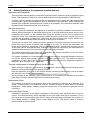
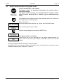
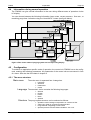
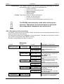
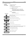
User's manual Pressurized enclosure system F850U manual rev.1 F850U Table of contents Page 2 ° Contents 1 1.1 1.2 2 GENERAL ........................................................................................................................................................4 General safety guidelines .............................................................................................................................4 Safety Guidelines for explosion proofed devices .........................................................................................5 INTRODUCTION: PRESSURIZED ENCLOSURE SYSTEM F850U ..............................................................6 2.1 Explosion protection: pressurized enclosure................................................................................................6 2.2 Pressurized enclosure system F850U..........................................................................................................6 2.2.1 F850U operation without solenoid valve ...............................................................................................6 2.2.2 F850U operation using a solenoid valve ...............................................................................................7 2.2.3 Integrating versus time based purging method .....................................................................................8 2.2.4 Pressurization using Continuous flow ...................................................................................................9 2.3 Peripherals..................................................................................................................................................10 3 INSTALLING THE UNIT/ GETTING STARTED ............................................................................................11 3.1 Classification...............................................................................................................................................11 3.2 General requirements according to NFPA 496 ..........................................................................................11 3.2.1 Enclosure.............................................................................................................................................11 3.2.2 Protective gas system .........................................................................................................................11 3.2.3 Power equipment.................................................................................................................................11 3.2.4 Type X Pressurizing ............................................................................................................................11 3.3 Mounting .....................................................................................................................................................12 3.3.1 Control unit FS850U ............................................................................................................................12 3.3.2 Operation only with nozzle, without solenoid valve.............................................................................12 3.3.3 Solenoid valves ...................................................................................................................................13 3.3.4 Operator panel BT851 .........................................................................................................................13 3.3.5 Protective gas supply ..........................................................................................................................13 3.4 Connecting and Commissioning.................................................................................................................14 3.4.1 Intrinsically safe connectors of FS850U ..............................................................................................15 3.4.2 Connection table FS850U and DW812 ...............................................................................................15 3.4.3 Power terminals of FS850U ................................................................................................................16 3.5 Default parameters .....................................................................................................................................16 3.5.1 Reset ...................................................................................................................................................16 3.6 Automatic Purging process.........................................................................................................................17 3.7 Maintenance ...............................................................................................................................................17 3.8 Repairs........................................................................................................................................................17 4 4.1 4.2 4.3 4.4 4.5 4.6 OPERATION ..................................................................................................................................................18 Display ........................................................................................................................................................18 Keyboard.....................................................................................................................................................18 How to enter and leave the bypass mode ..................................................................................................19 Information during normal operation...........................................................................................................20 Configuration ..............................................................................................................................................20 Alarm and malfunction indications..............................................................................................................25 5 FLOW CHARTS.............................................................................................................................................26 6 ANNEX ...........................................................................................................................................................31 6.1 Tables .........................................................................................................................................................31 6.1.1 Size of orifice plate ..............................................................................................................................31 6.1.2 Table: Resulting Flow rates by Nozzle and pre pressure ...................................................................31 6.1.3 Table: Plate orifice Selection ...............................................................................................................31 6.2 Technical Details ........................................................................................................................................32 6.3 Intrinsically safe ports .................................................................................................................................32 6.4 Block diagrams ...........................................................................................................................................33 6.5 Dimensions .................................................................................................................................................34 6.6 Shut off schematic ......................................................................................................................................35 6.7 Control drawing...........................................................................................................................................36 6.8 List of Parameters.......................................................................................................................................37 Gönnheimer Elektronic GmbH phone: +49 (6321) 49919-0; fax: -41 Email: [email protected] F850U Table of contents Page 3 Device overview: 1 2 3 6 4 5 7 8 9 12a 12b 10 11 13 13 1: Intrinsically safe connector – BT851 2: Intrinsically safe connector - Peripherals 3: Housing - Intrinsically safe control unit / pneumatic devices 4: Connector reference pressure (environment) 5: Purge gas outlet 6: LC-Display Gönnheimer Elektronic GmbH 7: Purge gas inlet 8: Push buttons 9: Explosion proof housing - Clamping / power section 10: Earth connection 11: Solenoid valve fuse 12a: Terminals 11-18; 12b: Terminals 19 - 24 13: Threads ½ inch NPT for cable gland/conduit phone: +49 (6321) 49919-0; fax: -41 Email: [email protected] F850U 1 Safety Guidelines Page 4 General The symbols WARNING, CAUTION, NOTE This symbol warns of a serious hazard. Failure to observe this warning may result in injury, death or the destruction of property. This symbol warns of a possible failure. Failure to observe this caution may result in the total failure of the device, the system or even the whole application to which it is connected. This symbol highlights important information. 1.1 General safety guidelines To ensure safe and reliable operation, the notes and warnings contained in this manual must be observed. Caution, this device uses mains voltage! Failure to observe these warnings may result in serious personal injury or damage to property. The commissioning of this device may only be carried out by technically qualified personnel who must observe local safety regulations. Attention: Follow regulations for handling and installation of explosion proof devices in hazardous areas! Gönnheimer Elektronic GmbH phone: +49 (6321) 49919-0; fax: -41 Email: [email protected] F850U 1.2 2 Introduction: Pressurized enclosure system F850U Page 5 Safety Guidelines for explosion proofed devices Application and Standards This instruction manual applies to explosion protected control systems of type of protection types below. This apparatus is only to be used as defined and meets requirements of NEC500-516. It can be used in hazardous locations which are hazardous due to gases and vapours according to the explosion group and temperature class as stipulated on the type label. When installing and operating the explosion protected device as well as its periphery, the respective nationally valid regulations and requirements have to be observed. General Instructions Work on electrical installations and apparatus in operation is generally forbidden in hazardous locations, with the exception of intrinsically safe circuits. In special cases work can be done on nonintrinsically safe circuits, on the condition that during the duration of such work no explosive atmosphere exists. Only explosion protected certified measuring instruments may be used to ensure that the apparatus is voltage-free. Grounding and short circuiting may only be carried out, if there is no explosion hazard at the grounding or short circuit connection. The control unit has to have a back-up fuse as stipulated. The mains connection must have a sufficient short circuit current to ensure safe breaking of the fuse. To achieve an impeccable and safety device operation, please take care for adept transportation, storage and mounting, as well as accurate service and maintenance. Operation of this device should only be implemented by authorised persons and in strict accordance with local safety standards. The electrical data on the type plate and if applicable, the "special conditions" of the test certificate of UL of the FS850U have to be observed. ! For outdoor installation it is recommended to protect the explosion protected distribution and control system against direct climatic influence, e.g. with a protective roof. The maximum ambient temperature is 140°F (60°C) at T4, if not stipulated otherwise (please note temperature classes of hazardous area and refer to UL- certificate) Terminal compartment in explosion proof housing (Ex-d) When closing the explosion proof housing, please ensure, that all gaskets of the housing remain effective, and that all threads are in proper condition. Keep the explosion proof -box of the system always completely closed during normal operation and secure the top cover against loosening. Unused entries at the explosion proof -housing have to be closed with adequate and certified blind plugs, which are secured against self-loosening and turning. Maintenance Work The gaskets of all parts of the housings have to be checked for damages and replaced, if required. Terminals have to be tightened correctly. Possible changes in colour point to increased temperature. Cable glands, stopping plugs and flanges have to be tested for tightness and secure fitting. Intrinsically Safe Circuits Installation instructions in the testing certificates of intrinsically safe apparatus have to be observed. The electrical safety values stipulated on the type plate must not be exceeded. This is also important at the intrinsically safe circuits. When interconnecting intrinsically safe circuits it is to be tested, whether a voltage and/or current addition occurs. The intrinsic safety of interconnected circuits is to be ensured! Gönnheimer Elektronic GmbH phone: +49 (6321) 49919-0; fax: -41 Email: [email protected] F850U 2 Introduction: Pressurized enclosure system F850U 2 Introduction: Pressurized enclosure system F850U 2.1 Explosion protection: pressurized enclosure Page 6 The use of pressurized enclosures allows the operation of ‘non explosion protected’ devices in hazardous areas inside division 1 or division 2 areas according to NEC 500. The protection type ‘pressurisation’ is based on the principle of maintaining a constant pressure using air or a protective gas to prevent an explosive mixture forming near the device inside the pressurized enclosure. Before start-up, the pressurized enclosure must be purged with air or protective gas to remove any explosive mixture that may be inside the enclosure. After this purging period the pressurized enclosure system has to monitor the pressure inside the cabinet. If this pressure drops below (at least) 0.8 mbar the control unit switches off the line voltage to secure the devices inside the cabinet. Therefore the devices inside the pressurized enclosure have to be wired according the shut off schematic in section 6.6. 2.2 Pressurized enclosure system F850U The pressurized enclosure system F850U contains at least the control unit FS850U and an inlet nozzle or solenoid valve. The FS850U can be mounted in- or outside the enclosure. Furthermore, an operator panel is available for remote control. It is also possible to connect intrinsically safe peripherals (e.g. temperature, pressure sensors, switches) to the control unit FS850U. The pressurized enclosure system F850U can be configured in different modes. The following table gives a survey: Only nozzle, (no solenoid valve) Using solenoid valve and nozzle in line Manual mode Simple mode Automatic mode Pressure control mode Manual operated valve Simple inlet nozzle D-solenoid valve P-solenoid valve Table 1: Survey of operation modes 2.2.1 F850U operation without solenoid valve 2.2.1.1 Simple mode - Pressurization The easiest way is to have only a nozzle at the inlet of the cabinet. So a permanent airflow through the cabinet is achieved and after the programmed amount of air has passed the cabinet the control unit enables the output contacts. The disadvantage of this solution is the constant high usage of compressed air or protective gas. 2.2.1.2 Manual mode - Pressurization This configuration uses two nozzles and a manually operated valve. The small and the bigger nozzle are mounted in parallel and the valve is used to shut the bigger nozzle off. So for purging the valve is opened by the operator, a huge stream of air is flowing through the cabinet and purges it. After the programmed amount of air has passed the cabinet and the control unit has enabled the output contacts the operator can close the valve. So only a small stream of air is entering the cabinet trough the small nozzle to maintain the required overpressure. The advantage of this method is that after purging, the airflow is limited by the small nozzle and the use of purge medium over time is much lower than it would be without valve (see 2.2.1.1). Gönnheimer Elektronic GmbH phone: +49 (6321) 49919-0; fax: -41 Email: [email protected] F850U 2 Introduction: Pressurized enclosure system F850U Page 7 2.2.2 F850U operation using a solenoid valve This configuration is nearly the same as the one in section 2.2.1.2, only the manually operated valve is replaced by a solenoid valve operated by the control unit. So the change between small and big nozzle is done automatically. The advantage of this is the operator free operation of the system. After power up, the control unit will purge the cabinet, close the solenoid valve afterwards and maintain the overpressure in the cabinet through the small nozzle. After purging, the control unit FS850U holds the pressure inside the enclosure at a minimum of 0.3 inH2O (80 Pa). Two different solenoid vale techniques are available: digital working solenoid valve (SVD) technique or proportional working solenoid valve (SVP) technique. 2.2.2.1 Automatic mode - Pressurization (digital solenoid valve technique) While purging, the SVD is activated and a large amount of purge medium flows into the enclosure through a nozzle with a large cross section. After purging, the control unit turns off the SVD. The leakage compensation is done by a bypass choke, with a very small adjustable cross section (diameter 12 mil (0.3 mm) up to 40 mil (1 mm), inside the valve. The protective medium flowing into the enclosure is adequate to maintain a pressure of at least 0.3 inH2O (80 Pa). The pressure is monitored by the control unit FS850U by a proportional working pressure sensor. The maximum and minimum pressure of the enclosure is programmable within the configuration menu. If leakage losses grow up (e.g. by aging of cabinet’s seals) and cannot be compensated by the bypass, the enclosure is shut down! The FS850S works in automatic mode with time based purging method as well as with integrating purging method. These methods are illustrated in section 2.2.3. 2.2.2.2 Pressure control mode – Pressurization (proportional solenoid valve technique) The internal proportional working pressure sensors also allow the use of a proportional solenoid inlet valve. This valve is used as the actuator of a digital-working FS850U PID-control loop for the inner pressure of the cabinet. The benefits of pressure feedback control are: 1. Dramatically decreased consumption of purge gas. 2. Increased availability of the application, based on constant pressure inside Ex-p-housing; higher leakages e.g. by aging of gaskets etc. will be compensated. Æ Adaptive compensation of leakage losses of the Ex p encapsulation! 3. Minimization of streaming noise. 4. Easy adjustment of pressure levels to specifications of Ex-certificate. Further advantages are: 1. Exact regulation of pressure also during purging phase. 2. By defined pressure inside cabinet, pressure sensible parts like foil keyboards, windows etc. will not be damaged. Gönnheimer Elektronic GmbH phone: +49 (6321) 49919-0; fax: -41 Email: [email protected] F850U 2 Introduction: Pressurized enclosure system F850U Page 8 Increased system availability by PID controlled cabinet pressure! Pressure sensitive parts (e.g. windows, front foils) will be saved. 2.2.3 Integrating versus time based purging method For purging in automatic mode (see section 2.2.2.1), a conventional (time based) as well as an improved integrating purging method (integration of real flow) are available: 1. Using the conventional method, the purge quantity is based on the product of a monitored minimum flow rate at the enclosure outlet and time. The flow rate depends on the size of the valve’s nozzle (diameter 40 mil (1 mm) ...240 mil (6 mm)) and supply pressure. This has to be calculated using a formula or a pressure-nozzle diagram. The conventional purging method using a digital valve has a considerable disadvantage: During purging phase and also while normal operation, a constant rate of protective gas is needed. For getting system availability the inflow rate has to be selected bigger than the leakage losses of the enclosure. Inflow volume – leakage losses of cabinet > preselected minimum flow rate! Wastage of protection gas will pollute environment and cause high costs dur- Durchfluss Flow ing application’s life time! A1+A2: berücksichtigte A1+A2: considered purge Spülmittelmenge gas volume with “integrating” purge method ! beim integrierenden Vorspül-Verfahren A2 Minimum Durchflussflow minimum A1 Pmin A2: unberücksichtigte A2: unconsidered purge gas volume Spülmittelmenge (wastage) (Verschwendung) A1: considered purge gas A1: berücksichtigte volume at conventional Spülmittelmenge bei (time-based) purging herkömmlichem Vorspülen Prepressure valve Vordruck amat Ventil Pmax Figure 1: Wastage of protective gas by detection of flow threshold and fixed purging time. 2. Using the improved integrating purging method, the FS850U unit measures the real flow rate at the enclosure outlet and integrates the signal to get the real purged volume. Additionally, a minimum flow rate is monitored to ensure a safe purging phase. If the flow rate sinks below the minimum, the integration will be stopped and continues automatically by rising above the minimum. Gönnheimer Elektronic GmbH phone: +49 (6321) 49919-0; fax: -41 Email: [email protected] F850U 2 Introduction: Pressurized enclosure system F850U Page 9 Increased inflow volume into the cabinet automatically leads to a shortening of time for purging when using the integrating purge method. This fast and efficient purge method enables shortest start-up times! 2.2.4 Pressurization using Continuous flow All modes above support also the operation mode „continuous flow“. This operation mode is used, for so called “containment systems”, where flammable gases or liquids will be emitted into the inner of the cabinet during normal operation (e.g. at analysers). After the purging phase, a continuous, PID controlled flow rate will be kept during normal operation. This continuous flow rate is used for thinning flammable gases or vapours below their “lower explosion concentration”. In Continuous flow operation mode, an adjustable minimum flow rate (additional F850U- parameter) will be monitored by purging and in normal operation. Gönnheimer Elektronic GmbH phone: +49 (6321) 49919-0; fax: -41 Email: [email protected] F850U 2.3 2 Introduction: Pressurized enclosure system F850U Page 10 Peripherals 2.3.1 Additional Pressure monitor DW812 Separate monitoring of two cabinets using an additional pressure monitor DW812 The FS850U is able to monitor two different cabinets separately and simultaneously. This application can be used e.g. at analyzers, using two different purge mediums. The first enclosure is monitored by the FS850U itself, the second enclosure is monitored by the pressure monitor DW812, connected to the separate inputs of the FS850U. The pressure monitor will be installed, like a control unit, as a purge medium drain on the second cabinet. For this, the DW812 has to be connected to the intrinsically safe plug connector 2 of the control unit FS850U (see chapter 3.4.1) and has to be initialized into it’s configuration menu. See the schematics in Figure 2. 0123 DW 812 1 2 F2 monitored flow rate Caption Connection table FS850U and DW812 FS850U DW812 Ex i Plug2 terminals FS850U F1 monitored flow rate VPurge 2 Prop. Valve1 valve 2.1 2.2 2.3 2.4 3 0 2 1 VPurge 1 21 22 19 20 Solenoid valve 2 Solenoid valvel 1 Ex p cabinet 2 Ex p cabinet 1 Figure 2 Monitoring of two Ex p cabinets The purging time respectively purging volume of both enclosures can be calculated and entered separately. By reason of principle, the integrating purging method as well as the PIDcontrolled cabinet pressure cannot be used at the cabinet monitored by the DW812. 2.3.2 Operator panel BT851 For the control unit FS850U an optional operator panel for remote control and visualization is available. The panel is based on the explosion protection class 'intrinsically safety' and offers an improved operator access when the FS850U control unit is mounted inside the cabinet. The operator panel BT851 indicates operation and malfunction status as plain text via LC-display. Four front-sided push-buttons offer total command of the FS850U unit. Status, momentary pressure, flow rate as well as remaining purge volume/time are available. The connection to the control unit is based on serial communication, using only 3 wires (max. distance 20m). Gönnheimer Elektronic GmbH phone: +49 (6321) 49919-0; fax: -41 Email: [email protected] F850U 3 3 Installation Page 11 Installing the unit/ Getting started This chapter contains important steps for mounting, connecting and starting. 3.1 Classification The UL has classified the FS850U for use in Class I, Division I, Groups BCD and it is a Type X system through NFPA 496 3.2 General requirements according to NFPA 496 3.2.1 Enclosure The protected enclosure, including windows, shall be constructed of material that is not likely to be damaged under the conditions to which it may be subjected. Precautions shall be taken to protect the enclosure from excessive pressure of the protective gas supply. In Division I and Zone I locations, where the conduit or raceway entry into a pressurized enclosure is not pressurized as part of the protective system, an explosion-proof conduit seal shall be installed as close as practicable to, but not more than 450mm (18 in.) from, the pressurized enclosure. 3.2.2 Protective gas system The protective gas shall be essentially free of contaminants or foreign matter and shall contain no more than trace amounts of flammable vapour or gas. All protective gas supplies shall be designed to minimize changes for contamination. Air of normal instrument air quality, nitrogen, or other non-flammable gas shall be permitted as a protective gas. Piping for the protective gas shall be protected against mechanical damage. Where compressed air is used, compressor intake shall be located in an unclassified location. Where the compressor intake line passes through a classified location, it shall be constructed of non-combustible material, designed to prevent leakage of flammable gases, vapors, or dusts into the protective gas, and protected against mechanical damage and corrosion. The electrical power for the protective gas supply (Blower, compressor, etc.) shall be supplied either from a separated power source or from the protected enclosure power supply before any service disconnectors to the protected enclosure. Where “double pressurization” is used, the protective gas supplies shall be independent. 3.2.3 Power equipment Enclosures containing power equipment shall be substantially non-combustible construction and shall be reasonably tight, Gaskets shall be permitted. 3.2.4 Type X Pressurizing No valves shall be permitted between the cutoff switch and the protected enclosure. Equipment, such as motors or transformers, that may be overloaded shall be provided with devices to detect any increase in temperature of the equipment beyond its design limits and shall de-energize the equipment automatically. For ventilated equipment, the flow of protective gas shall provide sufficient cooling even during overload conditions, or the equipment subject to overloading shall be provided with devices to de- Gönnheimer Elektronic GmbH phone: +49 (6321) 49919-0; fax: -41 Email: [email protected] F850U 3 Installation Page 12 tect any increase in temperature beyond its design limits and to de-energize that equipment automatically. 3.3 Mounting 3.3.1 Control unit FS850U The control unit FS850U can be placed directly inside hazardous area. The location (inside or outside the enclosure) as well as the position is variable and can be fitted to customers specific requirements. If possible, arrange the in- and outlet of the control unit on a horizontal axis. See also Figure 15 in the Appendix. The control unit can be fitted to the cabinet or to a mounting plate using the 4 integrated, rear sided fixing points. In most applications, the FS850U is fixed using the 1 inch screw connection of inlet or outlet. The solenoid inlet valve(s) (or inlet nozzle) should be mounted as far away from the control unit FS850U as possible, to achieve safe purging! (E.g. diagonal arrangement, see Figure 15). Watch local safety guidelines and NEC 500-516! For Class I Groups B, C & D Conduit Seals are required within 18”. If the FS850U is mounted inside the enclosure this conduit seals are also required. 3.3.2 Operation only with nozzle, without solenoid valve The inlet nozzle has to be mounted into a drilling into the pressurized housing using a counter nut with a protective gas supply adapter. It is not allowed to mount the nozzle on a bushing inside the pressurized enclosure. Figure 3 Mounting the nozzle into the housing. [inch (mm)] Please see table in section 6.1.2 to choose the adapted nozzle diameter to your system. Gönnheimer Elektronic GmbH phone: +49 (6321) 49919-0; fax: -41 Email: [email protected] F850U 3 Installation Page 13 3.3.3 Solenoid valves Mounting position of solenoid valve is free. It can be mounted inside or outside the cabinet. For mounting hints, see additional manufacturer's guide of solenoid valve. The solenoid valve is not part of the UL Classification. 3.3.4 Operator panel BT851 The operator panel BT851.0 can be integrated directly into the enclosures outer skin. The BT851.5 has a separate housing for mounting on a plate or wall. For location and drill sizes see Figure 16: Dimensions and templates of BT851 in annex. 3.3.5 Protective gas supply The costumer has to supply restricted (or regulated) pre- pressure to the inlet nozzle. Please see table in section 6.1.2 to choose the adapted nozzle diameter, pre-pressure to your system. Gönnheimer Elektronic GmbH phone: +49 (6321) 49919-0; fax: -41 Email: [email protected] F850U 3.4 3 Installation Page 14 Connecting and Commissioning After mounting the FS850U, connect the power supply lines, the valve lines and other non- intrinsically safe lines to the terminals 11-24 into the explosion proof enclosure of the control unit FS850U. HIGH VOLTAGE! Beware of high voltages and currents when handling this device or power lines! Electric shocks can injure or kill! Ensure your installation is compliant to the following: NEC 500-516, certification and description documents of FS850U. Do not exceed terminal safety limits of each terminal. See limits in technical details or declarations of conformity. FOR CLASS I GROUPS B, C & D CONDUIT SEALS ARE REQUIRED WITHIN 18”. BT 851 1 2 3 1.1 1.2 1.3 1.4 Control unit FS850U Ex em[ib] IIC T6 control circuits terminal 1-10 intrinsically safe 24 - - Digital valve 1 Standard valve 22 Digital valve 2/ Alarm contact additional valve by continous flow 20 Proportional valve for pressure or flow rate regulation 25 26 Valve fuse + 21 2.1 2.2 2.3 2.4 Bypass key switch On/off switch External alarm loop - + 23 + 19 - + 15 16 17 18 main voltage 11 12 13 14 working current circuit Figure 4: Block diagram FS850U If an external key switch is used for enabling the bypass function, it can be helpful to set the bypass code at the FS850U to 9999 to prevent a secondary bypass function by bypass code from the control unit. The external key switch for the bypass function has to be connected to terminals 2.1 and 2.2 of the FS850U. Gönnheimer Elektronic GmbH phone: +49 (6321) 49919-0; fax: -41 Email: [email protected] F850U 3 Installation Page 15 It is possible to switch on and off the internal devices of the cabinet using the On/Off key at the FS850U control unit or at the BT851 operator panel. If this function should not be used, it is possible to short cut terminals 2.1 and 2.3 of the FS850U, to enable an automatic power on after purging phase. In this case, the On/Off-buttons at the control unit FS850U and BT851 are disabled. 3.4.1 Intrinsically safe connectors of FS850U Figure 5: Intrinsically safe connectors of FS850U (socket on FS850U) Connector FS850U 1.1 1.2 1.3 1.4 2.1 2.2 2.3 2.4 BT 851 Description 1 2 3 Terminals exclusively for connecting the operating panel BT 851 NC (+) signal for all Inputs below Input for external bypass key switch Input for external On/Off switch Input for external alarm loop 3.4.2 Connection table FS850U and DW812 To achieve separate monitoring of two cabinets using an additional pressure monitor DW812. Intrinsically safe connector 2 on FS850U Terminals on DW812 2.1 3 2.2 0 2.3 2 2.4 1 Gönnheimer Elektronic GmbH phone: +49 (6321) 49919-0; fax: -41 Email: [email protected] F850U 3 Installation Page 16 3.4.3 Power terminals of FS850U 3.5 Terminal FS850U Description 11,12 13,14 15,16 17,18 19,20 +,21,22 +,23,24 +,- Working current circuit 1 Working current circuit 2 Line voltage, neutral conductor Line voltage, outer conductor at AC Terminals for proportional solenoid valve Terminals for additional digital solenoid valve 2 Terminals for digital solenoid valve 1 Default parameters The following parameters are preset after connecting the FS850U to mains supply for the first time or after a reset of the control unit: Parameter Language Structure Pressure and flow Codes Display Comment English Mode: leakage compensation Type of valve: proportional External DW812: No Purging volume Min. flow while purging Min. pressure inside enclosure Max. pressure inside enclosure Set-point pressure while purging Set-point pressure while operating Signal pressure Main menu (M-Code) Bypass (By-Code) On/Off-Code (On/Off-C.) 000500 l 00.9 l/s 0.3 inH2O 6 inH2O 4 inH2O 0.8 inH2O 0.3 inH2O 0001 0002 0000 Shut down value for integration Shut down values (limits) for pressure inside housing Only at optional signalling contact The setting 0000 disables the code protection (not possible at M-Code) The setting 9999 disables bypass button at FS850U and BT851 3.5.1 Reset Hold red button ENTER-Button down, while powering on the FS850U to reset all parameters to default values in table 3.5. The Reset can not be made using the BT851! Gönnheimer Elektronic GmbH phone: +49 (6321) 49919-0; fax: -41 Email: [email protected] F850U 3.6 3 Installation Page 17 Automatic Purging process The control unit FS850U starts the purging process immediately after start up, if the minimum pressure of 0.3 inH2O (80 Pa) can be built up inside Ex p cabinet. Minimum pressure and minimum flow rate will be monitored simultaneously to ensure a safe purging process. If the purging flow rate drops below its minimum (e.g. temporary interrupt of air supply or temporary shut of the outlet), the purging process will be interrupted and the control unit continues purging, after the disturbance is removed. If purging pressure exceeds the min or max limits, the purging process will be terminated and the control unit will restart with a new purging process automatically after achieving purging conditions. The table below shows the minimum flow rate in accordance of the used orifice plate. Orifice plate in control unit 3.7 ∅ = 0.16 inch (4 mm) Monitored minimum flow rate 0,1 liters /sec. ∅ = 0.24 inch (6 mm) 0,2 liters /sec. ∅ = 0.39 inch (10 mm) 0,4 liters /sec. ∅ = 0.55 inch (14 mm) 0,9 liters /sec. ∅ = 0.71 inch (18 mm) 1,3 liters /sec. Maintenance Depending on the cleanness of the used purging gas, the pneumatic inlet and outlet parts of the FS850U as well as the solenoid valve and optional DW812 have to be checked regularly for pollution by e.g. oil, dust, etc. or corrosion to ensure a safe work of the application. 3.8 Repairs Repairs or maintenance at the FS850U or its peripheral parts may only be done by Gönnheimer Elektronic GmbH. Gönnheimer Elektronic GmbH phone: +49 (6321) 49919-0; fax: -41 Email: [email protected] F850U 4 4 Operation Page 18 Operation The user can interact with the FS850U purge control unit via the four front sided push buttons and LC- display respectively by using the external operator panel BT851. 4.1 Display The built-in display indicates menus, operation modes, present pressure or flow rate data, as well as malfunction. 4.2 Keyboard The four front sided keys have different functions depending on the present mode of operation. Key On/Off „Shift right“button BYPASS Mode Function normal operation Toggles the cabinet’s electronic devices on and off, if purging system state is ready running menu Shift cursor one position to right. normal operation Activates Bypass. Only for maintenance of the cabinet! Only allowed if no hazardous atmosphere is present! „Up“-button INFO /P/Q/T running menu normal operation „Down“-button MENU „Enter“-button running menu normal operation running menu Gönnheimer Elektronic GmbH Get menu next item Changes information shown on the display: present pressure, flow rate, remaining purge time respectively purge volume and present state of the purging system. Get previous menu item Enter or leave menu Initiates and confirms parameter input phone: +49 (6321) 49919-0; fax: -41 Email: [email protected] F850U 4.3 4 Operation Page 19 How to enter and leave the bypass mode Only for maintenance of the cabinet! Set bypass only if no hazardous atmosphere is present inside or around the cabinet! The bypass mode is denied, if it is possible that an explosive atmosphere can arise inside the Ex p- cabinet! (e.g. at containments systems) It is possible to enter bypass mode in each operation sate of the control unit. The origin state is normal operation. Press „Up“-button By-CODE 0002 Enter the bypass code using the “up”, “down” and “shift right” button. The ex works bypass code is ‘0002’. Confirm the right bypass code using the ENTER- key. Bypass Or On The bypass mode is now active. If the control unit is set to “automatic on” the display toggles between “bypass” and “On” and the relay contacts (Terminals 11,12 and 13,14) are closed. Leaving of bypass mode is done by the same procedure. Alternative to the use of the push buttons, the bypass mode can be called by using a key switch between intrinsically safe connector 2.1 and 2.2 Gönnheimer Elektronic GmbH phone: +49 (6321) 49919-0; fax: -41 Email: [email protected] F850U 4.4 4 Operation Page 20 Information during normal operation The FS850U can give several information to the user during different sates of operation via the LC-display. You can choose between the following information items: state, current pressure-, flow rate-, or remaining purge time- indication using the “down/INFO”- button (see figure below). Figure 6 Flow chart: states of purging system and corresponding display 4.5 Configuration To achieve an application specific mode of operation, the control unit FS850U has to be configured, entering the following parameters. All parameters of the control unit are structured in form of a menu. See also the flow charts in chapter 5. 4.5.1 The menu structure Main menu Language Structure Gönnheimer Elektronic GmbH The main menu is separated into 4 categories: • • • • Language Structure Parameters Codes The standard device contains the following languages: • • • • • German English French Dutch Spanish The purge system structure can be selected as follows: • • • • Operation mode: leakage compensation or continuous flow Valve type: digital or proportional solenoid valve Purge method: Integrating or time based Optional pressure monitor DW812 installed: Yes or No phone: +49 (6321) 49919-0; fax: -41 Email: [email protected] F850U 4 Operation Parameters This category contains the necessary parameters depending on the defined structure above. Examples for parameters are: • • • • • Codes Page 21 Purging volume/time Minimum flow while purging process Minimum pressure Maximum pressure Signal pressure The control unit has 3 different code words: • M-Code: to enter main menu • By-Code: to activate Bypass • E/A-Code: to switch encapsulated components on or off The FS850U enters stand by mode while running menu structure. That means: the solenoid valve is closed and the encapsulated components are switched off. 4.5.2 Description of the menu items The display of the control unit contains 8 digits. All names of structures and parameters will be shown in clear text or abbreviations. The table below shows some explanation of the menu items. The table can be used as a reference guide for programming the FS850U correctly. See also corresponding flow charts in section 5. Hierarchy 1.Level Structure 2.Level 3.Level Valves DW Ext. P-Valve D-Valve digital solenoid valve is connected. DW Ext. Y. DW Ext.N. Integra. Integ. Y Integ. N. Cont.Flow C. Flow Y. C. Flow N. Param. Gönnheimer Elektronic GmbH Pur. Time Description, Explanation Selecting 'valves’ specifies weather a proportional solenoid valve or a ............................... phone: +49 (6321) 49919-0; fax: -41 Integrates an additional pressure monitor DW812 to the purging system. (DW 812, Yes) DW 812, No No additional pressure monitor is used. Integrating purging method, Yes Chooses integrating purging method. Integration Purging method, No Selects time based purging method. Continuous Flow, Yes Activates the operation mode ‘continuous flow'. Continuous Flow, No Activates the operation mode ‘leakage compensation’. Purge time - Enter a fixed purge time in h/min/sec. (The purge time only appears, if the time based Email: [email protected] F850U 4 Operation Pur. Vol. ................................ Min.Fl. P. ................................ Min.Fl .O. ................................ Rated Fl. Min.Pres. Max.Pres. R. Pre. Pu. Rated Pr. Sig. press. Codes M-Code By-Code On/Off-C. Gönnheimer Elektronic GmbH Page 22 purging method is chosen) Purge volume – Enter a fixed volume in litres. (The purge volume only appears, if integration purging method is chosen; e.g. 5 x cabinet volume) Minimum flow rate during purging phase Minimum flow rate during normal operation (only at continuous flow) ................................ Flow rate set-point - At operation mode ‘continuous flow’ this flow rate will be regulated, while normal operation. ................................ Minimum pressure inside enclosure Only values above ≥ 0.3 inH2O can be entered. ................................ Maximum pressure inside enclosure Maximum pressure ≤ 11 inch H2O ................................ Pressure set-point during purging, This pressure value will be regulated during purging process. ................................ Pressure set-point during normal operation, This pressure value will be regulated during normal operation. ………………………. Pressure set-point , at under-run of this value, the signalling output relay opens (terminals 21,22). ................................ Menu code - Code to enter menu and leaving normal operation mode. The M-code could not switched of by setting M-Code =„0000“! ............................... Bypass code - Code to activate the bypass. The bypass code can be switched off by setting „0000“. The bypass code „9999“ blocks the bypass function. In that case a bypass can only be activated by key switch connected to intrinsically safe connectors 2.1 and 2.2. ................................ On/ Off code, enables switching on or off the encapsulated devices. The On/Off code word can be switched off, entering „0000“. phone: +49 (6321) 49919-0; fax: -41 Email: [email protected] F850U 4 Operation Page 23 4.5.3 Configuration Example ExampleEx p-System ⇒ Enclosure volume: 500 l ⇒ Language : English ⇒ Structure : • Operation mode: leakage compensation • Proportional solenoid valve ⇒ Parameters • • • • • Purging volume: 2500 l Minimum pressure of enclosure: 0.3 inH2O (80 Pa) Maximum pressure of enclosure: 6 inH2O (1500 Pa) Set-point pressure purging process: 4 inH2O (1000 Pa) Set-point pressure normal operation: 0.8 inH2O (200 Pa) ⇒ Codes • M- Code: 0001 • By-Code: 0002 • E/A-Code: 0000 (switched off) Procedure: M-Code Press the “Enter”-button to start main menu. The control unit calls for the M-code to be entered. The ex works M-code is ‘0001’. Press the “Enter”-button to enter M-Code. _000 Display shows ‘0000’, the far left digit is flashing. Use right key to step between the digits. to enter code ‘0001’, 0001 (the present M-Code). Confirm the code input by pressing “Enter”-button Sprache The main menu is active now. The first sub menu ‘Language’ appears on the display. The default language of ex works is German. To alter the language, press “Enter”. English On the left appears the word ‘English Press the “Enter”-key to confirm. Structure Gönnheimer Elektronic GmbH Category ‘Structure’ appears. phone: +49 (6321) 49919-0; fax: -41 Email: [email protected] F850U 4 Operation Page 24 Press the “Enter”-key to configure the Ex p-system structure. Valves The first item of the structure menu is the choice of the solenoid valve. Press the “Enter”-key to change state. D-Valve The present state is digital solenoid valve. Change the state by pressing “Up”-key - P-Valve The new state is now ’Proportional solenoid valve’. Confirm the change by pressing “Enter”-key. Cont.Flow This item is the operational mode 'continuous flow' or 'leakage compensation'. The ex works state is 'leakage compensation'. So skip this item by pressing the “Up”- key. Param. The structure menu is now finished. The main menu automatically continues with the pre-selected parameters. Start the parameter category by pressing the “Enter”- key. Pur. Vol. The first menu item ‘Purging volume’ appears. Press the “Enter”- key to enter the desired volume of ‘2500 l’. _00500 l To enter ‘2500 l’, use the input sequence as follows: 00_500 l 002500 l Confirm the input by pressing the “Enter”- key. Min Fl. P. The minimum flow while purging can be increased for special applications. In the sample, the default value should be kept. Min.Pres The desired minimum pressure of 0.3 inH2O (80 Pa) is already adjusted ex works. Continue skipping this menu item by pressing the “Up”- key or indicate it by pressing the “Enter”- key. Now enter the desired value for the maximum pressure. Modify the present parameter as shown above. Max.Pres. Gönnheimer Elektronic GmbH phone: +49 (6321) 49919-0; fax: -41 Email: [email protected] F850U 4 Operation 4 inH2O Page 25 The desired maximum pressure is 4 inH2O (1000 Pa) Codes The desired set-point pressure during purging process of 4 inH2O is already adjusted ex works. Continue passing this menu item by pressing the “Up”- key. The desired set-point pressure during normal operation must be adjusted. Modify the present parameter to 0.8 inH2O (200 Pa) as shown above. The parameter setting is completed now. The main menu continuous automatically with the sub menu codes. M-Code Modify M-Code to ‘0001’ as shown above. Please note: the M-Code cannot be set to ‘0000’. By-Code Modify bypass code to ‘0002’ as shown above. On/Off-C. Set the on/off code to switch the encapsulated devices on or off to ‘0000’. This code is disabled from now on. R. Pre. Pu Rated Pre. End The main menu settings are now completed. After pressing the Enter- key, the purging system is ready for operation. 4.6 Alarm and malfunction indications Alarm Ext.Alar Error message Error E. Gönnheimer Elektronic GmbH Cause Actions The external alarm occurred, i.e. the (If the external alarm loop is not external alarm loop is broken or acti- used, disable the external alarm vated by an additional safety device. loop by a shorting bridge) Cause Remedy EEPROM Read Error Restart the FS850U. If the error Stored configuration data is incom- remains, the unit has to be checked by manufacturer. plete or corrupt. phone: +49 (6321) 49919-0; fax: -41 Email: [email protected] F850U 5 5 Flow charts Page 26 Flow charts Figure 7 Flow chart: main menu Gönnheimer Elektronic GmbH phone: +49 (6321) 49919-0; fax: -41 Email: [email protected] F850U 5 Flow charts Page 27 Figure 8 Flow chart: language menu Gönnheimer Elektronic GmbH phone: +49 (6321) 49919-0; fax: -41 Email: [email protected] F850U 5 Flow charts Page 28 Figure 9 Flow chart: structure category Gönnheimer Elektronic GmbH phone: +49 (6321) 49919-0; fax: -41 Email: [email protected] F850U 5 Flow charts Page 29 End of menu. Codes Sig. Pres. Enter Signal pressure Rated Pr. Enter rated pressure during operation mode Min. Fl. O. Operation mode leakage compensation selected Enter minimum flow during operation mode Operation mode continous flow selected R. Pre. Pu. R. Pre. Pu. Enter rated pressure during purge mode Enter rated pressure during purge mode Operation mode continous flow and P-Valves selected Min. Fl. P. Purge method medium integration selected else P-Valves selected Max. Pres. Enter minimum flow during purge mode Enter Setpoint pressure monitor maximun Time based purge method selected Min. Pres. Enter Setpoint pressure monitor minimum Pur. Time Pur. Vol. Enter purge time Enter purge volume time based Purge method selected Purge method medium integration selected Rated Fl. else Enter rated flow Operation mode continous flow and P-Valves selected Submenu Parameter Gönnheimer Elektronic GmbH End of menu. Structur phone: +49 (6321) 49919-0; fax: -41 Email: [email protected] F850U 5 Flow charts Page 30 Figure 10 Flow chart: parameter category Figure 11 Flow chart: code category Gönnheimer Elektronic GmbH phone: +49 (6321) 49919-0; fax: -41 Email: [email protected] F850U 6 Annex 6 Annex 6.1 Tables Page 31 6.1.1 Size of orifice plate Orifice plate ∅ = 0.16 inch (4 mm) Flow rate is about 0.14 .. 0.31 liters /sec. ∅ = 0.24 inch (6 mm) 0.31 .. 0.75 liters /sec. ∅ = 0.39 inch (10 mm) 0.69 .. 1.81 liters /sec. ∅ = 0.55 inch (14 mm) 1.67 .. 3.06 liters /sec. ∅ = 0.71 inch (18 mm) 2.5 .. 4.12 liters /sec. The right diameter of the orifice plate depends on the desired flow rate through the enclosure. In case of digital solenoid valve, the flow rate is mainly given by the built in nozzle diameter and pre pressure. 6.1.2 Table: Resulting Flow rates by Nozzle and pre pressure The air flow into the housing is a function of the pre pressure and the diameter of the nozzle. The table below shows the resulting air flow by given pre pressure and nozzle diameter. Flow in [l/s] pre pressure [bar] [100000Pa] 1,5 2 2,5 3 3,5 4 5 ρ Air = 1,293 g/liter pre pressure [inH2O] 602,2 802,9 1003,7 1204,4 1405,1 1605,9 2007,4 1,5 0,7 0,8 1,0 1,1 1,2 1,3 1,5 Nozzle diameter [mm] 2 3 1,2 2,7 1,5 3,4 1,7 3,9 1,9 4,4 2,1 2,3 2,6 4 4,9 6.1.3 Table: Plate orifice Selection Dependent on the air flow in the table 6.1.2 above it is recommended, to use a minimum size of the orifice plate. The table 6.1.3 is similar to table 6.1.1. The customer can choose the plate orifice in correspondence to given pre pressure and nozzle diameter. Plate orifice [mm] pre pressure [bar] [100000Pa] 1,5 2 2,5 3 3,5 4 5 pre pressure [inH2O] 602,2 802,9 1003,7 1204,4 1405,1 1605,9 2007,4 Gönnheimer Elektronic GmbH 1,5 min. 6 min. 6 min. 10 min. 10 min. 10 min. 10 min. 10 Nozzle diameter [mm] 2 3 min. 10 min. 14 min. 10 min. 14 min. 10 min. 18 min. 14 min. 18 min. 14 min. 14 min. 14 phone: +49 (6321) 49919-0; fax: -41 4 min. 18 Email: [email protected] F850U 6.2 6 Annex Page 32 Technical Details Control unit FS850U General Housing Electrical specifications Mounting Ex protection class Environment protection Dimensions Material Power consumption Main voltage Pneumatic Mounting Ex p Configuration Working circuits Terminal 11, 12, 13, 14 Control circuits, Plugs for peripheral components Pressure range Flow rate range Position Environment temperature Humidity Parameter input Parameter storage 6.3 inside hazardous area Explosion proof with I.S. Outputs, Class I, Division 1, Groups B, C, D, T6, Purged Type X NEMA 4X / IP65 H x W x D: 10.51 inch x 5.24 inch x 4.33 inch 267 mm x 133 mm x 110 mm Aluminum, lacquered, light grey (RAL 7035) About 2.5 VA (without peripherals) 110V AC, 120V AC, 230V AC 48 ... 62 Hz AC: U ≤ 250VAC, I ≤ 16A at cos ϕ > 0,7 DC: U ≤ 30 VDC, I ≤ 7 A, P ≤ 150 W Ex protection class: intrinsically safe, see declaration of conformity in UL certificate for further details 0 ... 7 inH2O (0 .. 1744 Pa) 0.14 .. 4.17 l/s, dependent upon orifice plate size Position independent, only intake and outlet of the control unit should be lined up on a horizontal axis. -10°C ...+50°C at T6 -10°C ...+60°C at T4 5-95%, non-condensing LC-Display, menu guided Different languages : German, English, French, Dutch, Spanish by EEPROM double saved with CRC Intrinsically safe ports Intrinsically safe inputs and outputs Terminal Voltage U0 Current I0 Power P0 C0, L0 8.61V 51mA 108.4mW 100nF, 1.1 40µH 8.61V 51mA 108.4mW 100nF, 1.2 40µH 1.3 2.1 8.61V 1.93mA 4.16mW 0nF, 40µH 2.2 8.61V 1.93mA 4.16mW 0nF, 40µH 2.3 8.61V 1.93mA 4.16mW 0nF, 40µH 2.4 Comment Supply BT851 Data BT851 Gnd BT851 Power supply Bypass-Input, Ext Q > min On/Off-Input, Ext P > min External alarm input, Ext P > max Table 2: Intrinsically safe ports Gönnheimer Elektronic GmbH phone: +49 (6321) 49919-0; fax: -41 Email: [email protected] F850U 6.4 6 Annex Page 33 Block diagrams Figure 12 Electrical block diagram Mech. valve Orifice plate Ex p- enclosure Spark lattice q.-prop. p.-prop. Terminals on FS850U Terminals on FS850U 20 19 A P Nozzle Operation mode leakage compensation using proportional solenoid valve 23 24 A Nozzle P Bypass-choke Operation mode: leakage compensation using digital solenoid valve Figure 13 Pneumatic block diagram Dimensions Gönnheimer Elektronic GmbH phone: +49 (6321) 49919-0; fax: -41 Email: [email protected] F850U 6.5 6 Annex Page 34 Dimensions Units: inch (mm) Figure 14: Dimensions FS850U Figure 15: Mounting examples Figure 16: Dimensions and template BT851.0 Figure 17: Dimensions and template BT851.5 Figure 18: Dimensions digital solenoid valve Gönnheimer Elektronic GmbH Figure 19: Dimensions proportional solenoid valve phone: +49 (6321) 49919-0; fax: -41 Email: [email protected] F850U 6.6 6 Annex Page 35 Shut off schematic If this pressure drops below (at least) 0.8 mbar the control unit FS850U switches off the line voltage to secure the devices inside the cabinet. The shut off of the ignition capable devices has to be done on both wired (Outer nad neutral) according the schematic below Do not exceed the maximum switching power of FS850U relay contacts in technical details table in section 6.2. Gönnheimer Elektronic GmbH phone: +49 (6321) 49919-0; fax: -41 Email: [email protected] F850U 6.7 6 Annex Page 36 Control drawing Figure 20: Control drawing - F850U.901 Gönnheimer Elektronic GmbH phone: +49 (6321) 49919-0; fax: -41 Email: [email protected] F850U 6.8 6 Annex Page 37 List of Parameters System identification Installation no.: Date: FS850U. . Production no.: Solenoid valve Inputs Description Language F850S language Display Value/ state Language Structure Valve Solenoid valve type used with this purging system? Valves P-Valve D-Valve DW Ext. Y. DW Ext. N. Integ. Y. Integ. N. C. Flow Y. C. Flow N, Tick box additional DW 812 Use of an additional DW 812? DW Ext. Tick box Purging Time based purging method method (Integ N.) or integration purging method (Integ. Y.) N.) Cont. Flow Tick box Purge time Pur. Time Purge volume Pur. Vol. Minimum flow rate during purging procedure Min. Fl. P. Minimum flow rate during normal operation by op. mode continuous flow Set-point flow rate by operation mode continuous flow Min.Fl. O. Pressure monitor, minimum pressure Min. Pres. Pressure monitor, maximum pressure Max. Pres Set-point pressure during purging R. Pre. Pu. Set-point pressure during normal operation Rated Pr. Pressure monitor, alarm pressure Codes Integra. Tick box Operational Continuous flow (C. flow Y.) or mode leakage compensation (C. flow Parameters Rated Fl. Sig. Pr. Code for main menu M-Code Code for bypass By-Code Code to enable switching ignition-capable device On/Off-C. Gönnheimer Elektronic GmbH BT851 Yes - No phone: +49 (6321) 49919-0; fax: -41 Email: [email protected]