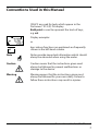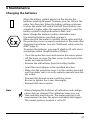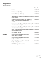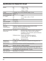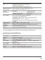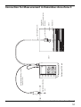
1
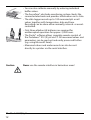
User Manual Portamess® 913 pH and Portamess® 913 X pH Warranty Defects occurring within 3 years from delivery date shall be remedied free of charge at our plant (carriage and insurance paid by sender). Sensors and accessories: 1 year. Subject to change without notice. Return of products Please contact our Service Team. Ship the cleaned device to the address you have been given. If the device has been in contact with process fluids, it must be decontaminated/disinfected before shipment. In that case, please attach a corresponding certificate, for the health and safety of our service personnel. Disposal Please observe the applicable local or national regulations concerning the disposal of “waste electrical and electronic equipment”. Knick Elektronische Messgeräte GmbH & Co. KG Beuckestr. 22 14163 Berlin, Germany Tel. +49-30-80191-0 Fax +49-30-80191-200 Internet: http://www.knick.de [email protected] Changes for Software Version 3 In addition to one- and two-point calibration, the meter can perform a threepoint calibration. Three-point calibration must be activated in a new configuration step (3P-CAL On/OFF, see page 20). During calibration, you can stop the procedure after each completed buffer evaluation by pressing the meas key. Depending on the number of buffer evaluations made, the meter performs a one-, two-, or three-point calibration. With three-point calibration the zero and slope are calculated using a mean straight line (to DIN 19268). Therefore, there is still only one zero point and one slope for Sensoface® evaluation. The calibration record has been supplemented by the third buffer. 3 Safety Precautions Be sure to read and follow these instructions! If you have to open the Portamess® 913 X pH to change the batteries, make sure that it is outside the hazardous area. If repairs are necessary, the meter must be sent in to the factory. Never operate the remote interface or printer within a hazardous area. Whenever it is likely that the protection has been impaired, the meter shall be made inoperative and secured against unintended operation. The protection is likely to be impaired if, for example: • the meter shows visible damage • the meter fails to perform the intended measurements • after prolonged storage at temperatures above 70 °C • after severe transport stresses Before recommissioning the meter, a professional routine test according to EN 61 010-1 shall be performed. This test should be carried out at our factory. Information 4 Safety Information Additional safety notes for ATEX The Portamess® 91. X pH portable pH meter has been designed and manufactured under consideration of the valid European standards and regulations and is suitable for use in areas with an explosion hazard. Compliance with the harmonized European standards for use in hazardous areas is confirmed by the declaration of conformity and the EC-type-test certificate. These are included in the user manual. When using the Portamess® 91. X pH portable pH meter, the conditions of EN 60079-14 “Electrical systems in hazardous areas” must be observed. Prerequisite to safe use of the equipment is the observance of the specified ambient conditions and temperature ranges. Never open the meter inside a hazardous area. Warning For applications in hazardous locations, only use the battery types listed in the table below. The batteries must be from the same manufacturer and of identical type and capacity. Never use new and used batteries together. Batteries for applications in hazardous locations Batteries (3 x each) Temp. class Ambient temperature range Duracell MN1500 T4 –10 °C ≤ Ta ≤ +40 °C Energizer E91 T3 –10 °C ≤ Ta ≤ +50 °C Power One 4106 T3 –10 °C ≤ Ta ≤ +50 °C Panasonic Pro Power LR6 T3 –10 °C ≤ Ta ≤ +50 °C Additional safety notes for ATEX 5 Application in hazardous locations of Zone 0 Warning When using the equipment in hazardous locations of Zone 0, there is a danger of releasing explosive atmosphere and penetration by flames from outside into the hazardous area Zone 0. The following should therefore be observed: The Model ZU 6979 X0 pH/Pt1000 combination electrode, connected to the pH/temperature measuring loop of the Model 91. X portable pH meter, may only be used briefly in portable application in containers with Zone 0. The Model ZU 6979 X0 pH/Pt1000 combination electrode may only be used for portable application in the hazardous area Zone 0 when the ground terminal is connected to the local equipotential bonding (see page 53). The Portamess® 91. X pH portable pH meter itself (handheld unit) may only be used in hazardous areas Zone 1. Application in Hazardous Locations of Zone 0 6 Conventions Used in this Manual ITALICS are used for texts which appear in the Portamess® 913 (X) PH display. Bold print is used to represent the texts of keys, e.g. cal. Display examples or keys whose functions are explained are frequently shown in the left-hand column. Note Notes provide important information which should always be observed when using the meter. Caution Caution means that the instructions given must always be followed to prevent malfunctions or damage to the device. Warning Warning means that the instructions given must always be followed for your own safety. Failure to follow these instructions may result in injuries. Conventions Used in this Manual 7 Table of Contents Safety Precautions.......................................................................... 4 Be sure to read and follow these instructions!.......................................4 Additional safety notes for ATEX..................................................................5 Application in hazardous locations of Zone 0........................................6 Conventions Used in this Manual.................................................. 7 1 The Model 913 (X) pH ................................................................ 11 Package contents ...........................................................................................11 Intended use / Short description . ............................................................11 2 Operation ................................................................................... 13 Meter design ....................................................................................................13 Display ................................................................................................................14 Keypad . ..............................................................................................................14 Sensoface® electrode monitoring ............................................................16 Connection and start-up .............................................................................16 Configuration ...................................................................................................18 Calibration..........................................................................................................22 Measurement....................................................................................................27 Data memory.....................................................................................................28 Data logger........................................................................................................29 Clock mode........................................................................................................31 Serial interface..................................................................................................32 Standard settings for ZU 0244 Lab Printer.............................................33 Printing measured values and records....................................................33 3 Troubleshooting ........................................................................ 35 Sensoface® electrode monitoring..............................................................35 Error messages..................................................................................................36 4 Maintenance .............................................................................. 41 Changing the batteries . ...............................................................................41 Cleaning the meter ........................................................................................42 Table of Contents 8 Appendix ....................................................................................... 43 Accessories.........................................................................................................43 Specifications for Model 913 (X) pH.........................................................44 Specifications for ZU 0244 Printer.............................................................45 EC-Type-Examination Certificate................................................................46 Statement of Conformity..............................................................................49 EC Declaration of Conformity......................................................................50 Connection for Measurement in Hazardous Area Zone 0................53 5 General Information on Measurement .................................... 54 Notes on pH measurement..........................................................................54 Glossary.......................................................................................... 60 Index .............................................................................................. 62 Table of Contents 9 10 1 The Model 913 (X) pH Package contents Please check the completeness of the shipment after unpacking. The package should include: • Portamess® 913 (X) pH incl. batteries and sensor quiver • Carrying strap • User manual • Quickstart instructions in German, English and French • Interface cable incl. adapter • Paraly® transfer program Intended use / Short description • • • • • • The Portamess® 913 (X) pH is used for pH and temperature measurement in industry, environment, food processing and waste-water treatment. Operation of the Portamess® 913 X pH is also permitted in hazardous areas Zone 1. The meter meets the EMC requirements of 89/336/ EEC and the recommendations as per NAMUR NE 21. The meter is IP 66 protected to EN 60 529 (jet water from all directions). Temperature compensation is automatic with a Pt 1000 temperature detector, an NTC 30 kΩ (automatic recognition during power-on) or through manual temperature input. Calibration can be carried out with buffer solutions from various, preselectable buffer sets. The buffer is then automatically recognized by the Calimatic®. The Model 913 (X) pH 11 • You can also calibrate manually by entering individual buffer values. • The Sensoface® electrode monitoring system checks the connected electrode and provides information on its state. • The data logger records up to 100 measured pH or mV values together with temperature, date and time. Recording can be done either manually, interval- or eventcontrolled. • Only three alkaline AA batteries are required for uninterrupted operation for approx. 2,000 hours. • The Paraly® software allows complete remote control of the Portamess® 913 (X) pH via PC. All measured values and parameters can be read out and easily processed further (e.g. using Microsoft Excel). • Measured values and meter record can also be sent directly to a printer via the serial interface. Caution Never use the remote interface in hazardous areas! The Model 913(X) pH 12 2 Operation Meter design 1 3 2, 3 4 5 Electrode connection Reference electrode connection Temperature probe connection PC/printer interface connection Sensor quiver Operation 13 Display Rinse electrode Stir buffer Battery solution empty Electrode response time Wait, cal timer, electrode response Press cal key Measurement units Senso face® Temperature detection using Pt1000/ NTC Clock Zero/ slope Error message Read memory Secondary Write display memory Main display Manual temperature detection Keypad Pressing on/off switches the meter on or off. When the meter is switched off, one of the Sensoface® status indicators is visible in the display. After power-on, the meter automatically performs a self test and checks which temperature detector is connected. After that, it automatically goes to pH measuring mode. Note You can also switch the meter on by pressing meas. However, in this case only a short test is performed and the temperature detector is not identified. The meter assumes that the last temperature detector identified is used. Pressing meas returns the meter to measuring mode from any function. Pressing meas while in measuring mode selects the desired measured variable (pH or mV) for the main display. Operation 14 ▲ ▼ For manual temperature specification (no temperature detector connected), the temperature is set using and . These keys are also used to set the clock, to select the memory locations and to edit selected parameters. Pressing cal starts calibration. With calibration, the meter is adjusted to the electrode. You can choose between one or two-point calibration either using Calimatic® automatic buffer recognition or with manual buffer entry. Pressing clock switches the meter into the clock mode. All measurement processes are canceled and battery consumption is reduced to a minimum. Pressing STO activates the data memory for writing measured values. Pressing RCL activates the data memory for reading measured values. Pressing print sends the currently measured value to a printer or PC. Pressing RCL and print prints out the data stored in memory. Pressing cal and print prints out the meter record. + Note Pressing cal + on/off simultaneously when the meter is switched off, opens the configuration menu. Keep the cal key depressed and then press the on/off key. When pressing two keys at the same time, make sure that the key shown on the left is pressed first. Operation 15 Sensoface® electrode monitoring The Sensoface® automatic electrode monitoring system provides information on the electrode state. Zero point, slope, response time, impedance and drying out are evaluated. In addition, Sensoface® reminds you to regularly calibrate the meter. For more detailed information on the displayed electrode state and the individual evaluations of the parameters, please see chapter “Troubleshooting and Maintenance” (page 35). Connection and start-up Sensor connection Commercially available electrodes with a nominal electrode zero point of pH 7 and the following plugs can be connected: – Coaxial standard plug to DIN 19 262 and/or – 4-mm banana plug. Connection assignment Connection.................................................. Socket Combination electrode..................................................... 1 Single measuring electrode............................................ 1 Single reference electrode............................................... 3 Integrated temperature detector of combination electrodes.................................................... 2 Separate temperature probe......................................2, 3 Remote interface................................................................. 4 Operation 16 If no temperature detector has been connected, the meter operates with the manually set temperature and man appears in the display. Note If the Portamess® 913 (X) pH is connected to a PC and is used to take measurements in grounded liquid, measuring errors may result. Note Prior to first measurement, the buffer set to be used must be selected and the meter calibrated. If required, the clock must be set. Start-up With the meter switched-off, one of the Sensoface® status indicators is always visible. Note Even with the meter switched off, the calibration data and the contents of the data memory remain permanently stored. Pressing on/off switches the meter into measuring mode. After power-on, the meter determines the connected temperature detector and performs a self test: • Simultaneous appearance of all display segments, symbols and Sensoface® indicators • Display of Model No. 913 • Display of software version • Display of selected buffer set Note The temperature detector is only recognized during the power-on procedure after pressing on/off. Note The meter can also be switched on with meas. However, in this case only a short test is performed and the temperature detector is not identified. The meter assumes that the last temperature detector identified is used. Operation 17 Configuration Note If you calibrate using the Knick buffer set, generally you do not have to change the configuration. The following basic settings can be changed in the configuration: • Calibration timer interval • Automatic calibration (Calimatic®) on or off (manual), buffer set for automatic calibration • Three-point calibration on or off • Automatic switch-off after 1 hour or 12 hours • Remote interface: Printer output on/off, baud rate • Temperature display °C or °F • Date and time format 24 hours and day, month, year or 12 hours (am/pm) and month, day, year To activate the configuration, hold down cal with the meter switched off and then press on/off. + The menu items of the configuration menu are worked through in sequence. ▲ ▼ To change the setting of the respective menu item, press or . Pressing STO switches to the next menu item and saves the displayed settings. Pressing meas exits the configuration menu at any time. The value last displayed and possibly hanged will then not be saved. Operation 18 Calibration timer Automatic or manual calibration With the calibration timer, the period of time can be specified within which calibration should occur. The interval range is 0 to 1,000 hours. When approx. 80 % of the preset interval has passed, the calibration timer switches the Sensoface® display from to . When the total interval has run out, the display is set to . The timer is reset with a calibration. To switch off the calibration timer, enter 0 as the interval. (Factory setting: calibration timer off ). You can select whether you wish to calibrate with the Calimatic® automatic buffer recognition system or with manual entry of the individual buffer values. When calibrating with Calimatic® automatic buffer recognition (AutCal On), you only have to enter the buffer set used once in the configuration menu. The buffer values are stored at the correct temperature. During calibration the meter then automatically recognizes the buffer used (factory setting: automatic calibration on, Knick technical buffers). Select the buffer set with the buffers used in the buffer set selection. Various calibration buffer sets are stored in the Portamess® 913 (X) pH. The following buffer sets are permanently stored in the meter: BUFFER –00– Knick technical buffers pH 2.00 4.01 7.00 9.21 BUFFER –01– Mettler Toledo technical buffers (former Ingold) pH 2.00 4.01 7.00 9.21 BUFFER –02– Merck/Riedel pH 2.00 4.00 7.00 9.00 12.00 BUFFER –03– DIN 19 267 pH 1.09 4.65 6.79 9.23 12.75 BUFFER –04– Ciba (94) pH 2.06 4.00 7.00 10.0 Operation 19 BUFFER –05– BUFFER –06– BUFFER –07– Note Three-point calibration on/off Operation 20 NIST pH 1.68 4.00 7.00 10.01 12.46 DIN 19 266 and NIST (NBS) pH 1.679 4.006 6.865 9.180 HACH pH 4.00 7.00 10.18 The meter can only operate properly if the buffer solutions used correspond to the selected, activated buffer set. Other buffer solutions, even those with the same nominal values, demonstrate a different temperature behavior. This leads to measurement errors. For manual buffer specification (AutCal OFF), the pH value of the buffer solution must be entered for the correct temperature. This allows calibration using any other buffer solutions. You can choose whether you want to perform threepoint calibration in addition to one- or two-point calibration. With three-point calibration turned on (3P-Cal On), you can calibrate with a third buffer solution after twopoint calibration has been completed. The sequence of the buffer solutions is unimportant. With three-point calibration zero point and slope are calculated using a mean straight line (to DIN 19268). With three-point calibration turned off (3P-Cal OFF), only one- or two-point calibration is possible (default setting: (3P-Cal OFF). Automatic switch-off Interface Temperature display Time and date format To protect the batteries, the meter switches off automatically when not operated for a longer time. You can select whether switch-off is to take place after one hour or after twelve hours (factory setting: 1 hour). If the data logger is active and during remote interface operation, the auto switch-off feature is disabled. If the Portamess® 913 (X) pH is controlled by a PC and interface conflicts occur when the print key is pressed, you should deactivate the print function (Print OFF) (factory setting: Print On, 4,800 bauds). The transmission speed can be set to 600, 1200, 2400, 4800 or 9600 bauds. The transmission speed must correspond to that set in the printer or PC. Data format and protocol are permanently set to 7 bits, one stop bit, even parity and XON/XOFF protocol (NAMUR NE28). The temperature can be displayed either in °C or °F (factory setting: °C). The time and date format can be set to either 24 hours and day.month.year or 12 hours am/pm and month.day (factory setting: 24 hours and day.month.year). Operation 21 Calibration By calibration, the pH meter is adjusted to zero point and slope of the electrode used. Calimatic® automatic calibration For calibration using Calimatic® automatic buffer recognition, you only have to enter the buffer set used once in the configuration menu. With the patented Calimatic® system, the meter automatically recognizes the buffer solutions, calculates the electrode zero point and slope (based on 25 °C) and carries out the corresponding adjustment. It does not matter which buffer solution is taken first. Note The meter can only operate properly when the buffer solutions used correspond with the buffer set selected in the configuration menu. Other buffer solutions, even with the same nominal values, may demonstrate different temperature behavior, which leads to measurement errors. Pressing cal activates calibration. Calibration can be exited by pressing meas. If exited prior to entry of the first calibration point, zero and slope of the last calibration are displayed for a moment. Immerse electrode and temperature detector in the first buffer solution. This can be any of the selected solutions. Press cal again to calibrate to the first buffer solution. If you do not want to calibrate, press meas to cancel the process. During buffer recognition the lower line indicates the temperature while the hourglass indicator flashes. The nominal value of the recognized buffer solution is displayed for approx. 5 s. Electrode and temperature detector must remain in the first buffer solution until the display prompts for the second buffer. Operation 22 Note The response times of electrode and temperature detector are considerably reduced if you first move the electrode in the buffer solution and then keep it still to read the values. This provides stable values more quickly. The electrode stability is checked and the measured mV value displayed. Stability check can be overridden by pressing cal. However, this reduces calibration accuracy. Calibration with the first buffer is complete. Remove electrode and temperature detector from the first buffer solution and rinse off both thoroughly. • If you want to perform one-point calibration, press meas to terminate the calibration now. The meter then shows the newly determined zero point in the main display and the old slope in the lower display and returns to pH measuring mode. • For two-point calibration, immerse the electrode and temperature detector in the second buffer solution. Press cal to continue the calibration. The calibration process runs again as for the first buffer. Note Only with three-point calibration turned on (3P-CAL On, see page 20), the calibration menu offers the possibility to evaluate a third buffer solution after two-point calibration has been completed. With three-point calibration turned off (3P-CAL OFF, see page 20), the calibration procedure is automatically ended at this point. With three-point calibration turned on (3P-CAL On), you can now evaluate a third buffer solution. • For two-point calibration, press meas to terminate the calibration. The meter then shows the newly determined zero point in the main display and the new slope in the lower display and returns to pH measuring mode. Operation 23 • If you want to perform a three-point calibration, immerse the electrode and temperature detector in the third buffer solution. Press cal to continue the calibration. The calibration process runs again as for the previous buffers and is automatically terminated. Zero and slope are calculated using a mean straight line (DIN 19268). At the end of the calibration, the zero point and slope (based on 25 °C) of the electrode are displayed. Then the meter switches back to measuring mode. Manual calibration For calibration with manual buffer entry, you must first disable the Calimatic. Then, you must enter the pH value of the buffer solution used for the correct temperature. This allows to calibrate with any buffer solution. Pressing cal activates calibration. Calibration can be exited by pressing meas. In that case, zero and slope of the last calibration are displayed for a moment. Enter the temperature-corrected pH of your buffer solution using and . Press cal to start calibration. The buffer value set is stored so that you do not have to enter it for the next calibration (which must be performed at the same temperature). If the temperature has changed, the pH value must be adjusted before proceeding. Note The response times of electrode and temperature detector are considerably reduced if you first move the electrode in the buffer solution and then keep it still to read the values. This provides stable values more quickly. The electrode stability is checked and the measured mV value displayed. Stability check can be overridden by pressing cal. However, this reduces calibration accuracy. Operation 24 Calibration with the first buffer is complete. Remove electrode and temperature detector from the first buffer solution and rinse off both thoroughly. • If you want to perform one-point calibration, press meas to terminate the calibration now. The meter then shows the newly determined zero point in the main display and the old slope in the lower display and returns to pH measuring mode. • For two-point calibration, immerse the electrode and temperature detector in the second buffer solution. Enter the pH value of the second buffer solution. Press cal to continue the calibration. The calibration process runs again as for the first buffer. Note Only with three-point calibration turned on (3P-CAL On, see page 20), the calibration menu offers the possibility to evaluate a third buffer solution after two-point calibration has been completed. With three-point calibration turned off (3P-CAL OFF, see page 20), the calibration procedure is automatically exited at this point. With three-point calibration turned on (3P-CAL On), you can now evaluate a third buffer solution. • For two-point calibration, press meas to terminate the calibration. The meter then shows the newly determined zero point in the main display and the new slope in the lower display and returns to pH measuring mode. • If you want to perform a three-point calibration, immerse the electrode and temperature detector in the third buffer solution. Enter the pH value of the third buffer solution. Press cal to continue the calibration. The calibration process runs again as for the previous buffers and is automatically terminated. Zero and slope are calculated using a mean straight line (to DIN 19268). At the end of the calibration, the zero point and slope (based on 25 °C) of the electrode are displayed. Then, the meter switches back to measuring mode. Operation 25 Converting slope % –> mV/pH Operation 26 % mV/pH % mV/pH 8 7 79 80 81 82 83 84 85 86 87 88 89 90 46.2 46.8 47.4 48.0 48.5 49.1 49.7 50.3 50.9 51.5 52.1 52.7 53.3 91 92 93 94 95 96 97 98 99 100 101 102 103 53.9 54.5 55.1 55.6 56.2 56.8 57.4 58.0 58.6 59.2 59.8 60.4 61.0 Measurement Measuring mode Pressing meas accesses the measuring mode from all functions. In the measuring mode, the main display indicates the measured variable and the secondary display shows the temperature. The measured variable is selected with meas. You can choose between the following variables: • pH • Electrode potential [mV] Note The response times of electrode and temperature detector are considerably reduced if you first move the electrode in the buffer solution and then keep it still to read the values. This provides stable values more quickly. Manual temperature specification The man indicator signals that no temperature detector is connected. The meter operates with the manually specified temperature. The specified temperature can be edited using and . Operation 27 Data memory Up to one hundred measured values can be stored in the data memory together with temperature, date and time. Storage is performed either manually or automatically using the data logger. The currently measured value (pH or mV) is stored Write memory At pressing STO, the currently measured value is shown in the display (HOLD). Now you can select any memory location using and . Press STO to store the measured value in the selected memory location. After storing, the memory location number is automatically incremented and the meter returns to measuring mode. Read memory Pressing RCL displays the last measured values stored. Now you can select any memory location using and . Pressing RCL switches between the measured value and time/date of storage. This allows, for example, searching for a value that was stored at a certain time. Pressing meas returns to measuring mode. Clear memory To clear the entire data memory, press STO to access memory mode and then clock to access data logger mode. Select Clear (Clr) using or . By confirming this with STO, the entire memory area is cleared. If you do not want to clear the memory, press meas to cancel. Operation 28 Data logger Data logger The data logger records up to 100 measured values together with temperature, time and date. Data storage is performed either manually (at the press of a key), interval- or event-controlled. The data logger always saves the currently measured variable (pH or mV). Press STO to access memory mode and then clock to access data logger mode. Now, choose between three different recording modes and the parameter setting of the data logger using or . Pressing STO confirms the selected mode. In the Continue and Start mode this also starts the data logger. The current memory location is shown in the display. If ”Clear“ has been selected, all memory locations are cleared and the meter returns to measuring mode. Pressing meas exits the data logger mode. Data logging modes After pressing STO, logging is continued after the memory location in which the last measured value was stored (continue). Press meas to exit logging. After pressing STO, the entire data memory is cleared without starting the data logger (clear). After pressing STO, the entire data memory is cleared. Storage begins from memory location “00” (start). Press meas to exit logging. Operation 29 Setting the data logger parameters In the parameter setting mode, you select whether data logging is to be interval-controlled, event-controlled or manual. Press STO to access the logging functions. To select interval-controlled logging of measured values, press STO and set the interval in which the recording is to take place using and . The interval range is between 5 seconds and 60 minutes. Default time (factory-set) is 2 minutes. After selecting your interval time, press STO to enter the value. With event-controlled data logging, a measured value is not saved until it deviates from the last memory value by the preset differential value. Using the time which is also stored, you can determine when the value has changed. The differential value is entered in the subsequent parameter-setting step. Note The differential value is always based on the currently set measured variable (pH or mV). This means that if differential pH values are to be logged, the meter must be set to pH measurement prior to parameter setting and data logging. With manual data logging, the measured values are saved by pressing STO. After selecting the above parameters, select “Continue” or “Start” using the and keys and then press STO to commence logging. Note Operation 30 The data logger does not stop after reaching the last memory location (99). Recording is automatically continued with memory location number 00. To avoid losing data by overwriting, download stored data and clear the logger before beginning a new set of data. Be aware of this when using interval-controlled data logging. Clock mode Pressing clock activates the clock mode. The time and date are displayed. In this mode, the battery consumption of the meter is reduced to a minimum. Setting the clock: To set the time or date, the clock mode must be activated. Press STO and clock simultaneously to set the clock. The time display flashes. The time can be set using and . When the correct time is displayed, press STO. Then set the date. When the correct date is displayed, press STO. Then set the year. Press STO to confirm the year. The meter returns to clock mode. Press the meas key to return to measuring mode. Operation 31 Serial interface Note If the Portamess® 913 (X) pH has been connected to a PC and measurement are taken in a grounded liquid, measurement errors may result. With the remote interface, you can directly send data to a printer with serial port or set up a direct connection to a computer. Via the computer, the meter can be completely remote controlled and all data and parameters can be read. Using the printer (e.g. Model ZU 0244), you can directly print measured values, stored data and records. Interface parameters The RS 232 interface can be defined for all common baud rates. Setting is carried out in the configuration menu • Baud rate: 600 Bd 1,200 Bd 2,400 Bd 4,800 Bd (default setting) 9,600 Bd Data format and protocol are permanently set to: • 7 data bits • even parity • one stop bit • XON/XOFF protocol Note For the command set of the Portamess® 913 (X) pH, refer to the online help of the Paraly® transfer software. Operation 32 Interface cable Printer PC Only one interface cable is required to operate a printer or PC. By simply turning the plug around on the Portamess® 913 (X) pH, the cable can be used to connect to either a printer or a PC. Connection assignment Standard settings for ZU 0244 Lab Printer Meter configuration Parameter Baud rate Printer Setting 4800 On Printing measured values and records Note Make sure that the print function is activated in the configuration (Print On) and the baud rate corresponds to that of the printer. Printing measured values Press print while in measuring mode to print out the currently measured value. The measured value is printed with temperature, date, time and a three-digit identification number. The identification number is reset when the meter is switched off. Printing the memory Press RCL and then print to print out the stored data. All data points are printed with temperature, date, time and memory location number (Sxx). Printing individual data points Press RCL. Select the desired data point using Press print to start printing. and . Operation 33 Note If Sensoface® was during data logging, the memory location will be marked with *, and if the measurement range (pH, mV, °C) was exceeded, it will be marked with #. Printing the record To print out the meter record, press cal, then print. The record printout contains: • a calibration record with the exact data from the last calibration, • the settings of the configuration menu, • a record of the last self-test and • a list of the current Sensoface® criteria. Operation 34 3 Troubleshooting Sensoface® electrode monitoring The automatic Sensoface® electrode monitoring system provides information on the electrode state. It evaluates zero point, slope and response time of the electrode. In addition, Sensoface® requests calibration at regular intervals. Note Sensoface® is specially designed for monitoring pH electrodes. Note The deterioration of the electrode condition is signified by or of the Sensoface® indicator (”smiley”). can only This evaluation is permanent. An improvement take place after a calibration. This Sensoface® indicator provides information on the electrode response time, i.e. on the amount of time an electrode requires to supply a stable measured value. The value is determined during calibration. Due to wear, aging and as the result of incorrect handling, e.g. drying out, the swelling layer of the glass membrane of an electrode may recede. This leads to a longer response time and the electrode becomes sluggish. The electrode response is slow. You should consider maintaining or replacing the electrode. It may be possible to achieve an improvement by cleaning or, for an electrode returned to duty after dry storage, by rehydrating. The electrode response is very slow. Correct measurement is no longer ensured. The electrode should be maintained. If appropriate maintenance fails to remedy the situation, the electrode should be replaced. Troubleshooting 35 This Sensoface® display provides information on the electrode zero point and the slope. Zero and slope of the electrode are still okay, however the electrode should be maintained or replaced soon. Zero and/or slope of the electrode have reached values which no longer ensure proper calibration. It is advisable to replace the electrode. Note The zero and slope values are determined during calibration. Therefore, the condition for accurate information is proper calibration. For this reason, always use fresh buffer solutions. Using the calibration timer, you can set an interval within which calibration should take place. The calibration timer continues to run with the meter switched off. Zero and slope of the electrode are still okay, however the electrode should be maintained or replaced soon. Zero and/or slope of the electrode have reached values which no longer ensure proper calibration. It is advisable to replace the electrode. Troubleshooting 36 Error messages Sensor problems ERROR 1 If there are problems with a sensor, an error message appears and the measured-value display flashes. Problem with the electrode Possible causes: • Electrode defective • Too little electrolyte in the electrode • Electrode not connected • Break in electrode cable • Wrong electrode connected • Measured pH less than –2 or greater than +16 ERROR 2 Problem with the electrode Possible causes: • Electrode defective • Electrode not connected • Break in electrode cable • Measured electrode potential is less than -1,300 mV or greater than +1,300 mV ERROR 3 Problem with the temperature detector Possible causes: • Temperature detector defective • Short circuit in temperature detector • Wrong temperature detector connected • Measured temperature less than -20 °C or greater than +120 °C Note When changing the temperature detector (also for electrodes with integrated temperature detector), note that the temperature detector type (Pt 1000/NTC 30 kΩ) is only recognized when the meter is switched on with on/off. Troubleshooting 37 Calibration If errors occur during calibration, or if the determined electrode data are outside the valid range, an error message error messages appears (ERROR 4 ... ERROR 11). ERROR 4 The electrode zero point determined during calibration is outside the permissible range. The zero point is less than pH 6 or greater than pH 8. This message appears in measuring mode following a calibration. It can only be remedied by recalibration with fresh buffer solutions. Possible causes: • Electrode ”worn out“ • Buffer solutions unusable or falsified • Buffer does not belong to configured buffer set • Temperature detector not immersed in buffer solution (for automatic temperature compensation) • Wrong buffer temperature set (for manual temperature specification) • Electrode used has different nominal zero point ERROR 5 The electrode slope determined during calibration lies outside the permissible range. The slope is less than 78 % or greater than 103 %. This message appears in measuring mode following a calibration. It can only be remedied by recalibration with fresh buffer solutions. Possible causes: • Electrode ”worn out“ • Buffer solutions unusable or falsified • Buffer does not belong to configured buffer set • Temperature detector not immersed in buffer solution (for automatic temperature compensation) • Wrong buffer temperature set (for manual temperature specification) • Electrode used has different nominal slope Troubleshooting 38 ERROR 8 The meter has recognized two identical buffer solutions. This message is only displayed during calibration. Calibration must be repeated with fresh buffer solutions. Possible causes: • Same or similar buffer solution was used for both calibration steps • Buffer solutions unusable or falsified • Electrode defective • Electrode not connected • Break or short circuit in electrode cable ERROR 9 The meter cannot recognize the buffer solution used. This message is only displayed during calibration. Calibration must be repeated with fresh buffer solutions. Possible causes: • Buffer does not belong to configured buffer set • Electrode defective • Electrode not connected • Break in electrode cable • Wrong buffer temperature set (for manual temperature specification) During manual calibration, the buffer solutions were not used in the specified order. Calibration must be repeated. ERROR 10 ERROR 11 Calibration was cancelled after approx. 2 minutes because the electrode drift was too large. This message is only displayed during calibration. Calibration must be repeated with fresh buffer solutions. Possible causes: • Electrode defective or dirty • No electrolyte in the electrode • Electrode cable insufficiently shielded or defective • Strong electric fields influencing the measurement • Major temperature fluctuation of the buffer solution • No buffer solution or extremely diluted Troubleshooting 39 ERROR 14 If the clock has not been set, e.g. after battery replacement, this error message is displayed. To clear the message, set the clock (see page 31). ERROR 15 If errors occur during transmission via the RS 232 interface, this error message appears. This message will not occur if ”Printer On“ is configured. Possible causes: • No valid end character transmitted (receiver overflow) • Wrong transmission rate (baud rate) set (see page 21) • Error during transmission • Wrong data format (see page 21) e.g. parity bit ERROR 18 If the meter detects an error during the self-test, this error message appears. Possible causes: • Configuration or calibration data are defective. Completely reconfigure and recalibrate the meter. Error in the factory settings or system memory. FAIL appears in the display. Possible causes: • EPROM or RAM defective • Error in meter factory settings ERROR 19 Note This error message should normally not occur as the data are protected from loss by multiple safety functions. Should this error message nevertheless appear, no remedy is available. The meter must be repaired and recalibrated at the factory. Troubleshooting 40 4 Maintenance Changing the batteries When the battery symbol appears in the display, the batteries need replacement. However, you can still use the meter for a few days. When the battery voltage continues to drop, the meter will switch itself off. (Since battery consumption is higher when the remote interface is used, the battery symbol is displayed earlier in that case.) Never change the batteries within a hazardous area. Use only the batteries specified on page 5. Make sure that the meter is carefully closed again and that the protective cover is properly mounted on the meter after changing the batteries (see also “Additional safety notes for ATEX“, page 5). To replace the batteries, you need 3 alkaline AA cells and a screwdriver (either straight-blade or Philips). • Close the protective cover and remove the sensor quiver. • Lift the hook, unscrew the four screws on the back of the meter and remove the lid. • Remove the old batteries from the battery holder. • Insert the new batteries in the specified direction. • Make sure the protective cover is in the notches provided and the rubber seal is correctly seated, especially near the pH socket. • Remount the lid and secure it with the screws. Be sure to tighten the screws thoroughly. • Remount the sensor quiver. Note When changing the batteries, all calibration and configuration data are retained. The calibration timer runs out. Time and date must be reset. The meter switches to pH measurement (as does the event-controlled data logger). The current memory location is set to 00. Maintenance 41 Caution If you want to store the meter for a longer time, the batteries must always be removed beforehand. Leaky batteries may damage the meter. Cleaning the meter To remove dust and dirt, the external surfaces of the meter may be cleaned with water, and also with a mild household cleaner if necessary. Caution Maintenance 42 Beware of electrostatic charging when using the meter in hazardous areas! For example, never wipe the meter with a dry cloth. Appendix Accessories Ref. No. Printer ZU 0244 Printer paper (5 rolls) ZU 0249 Printer ribbon (5 ribbons) ZU 0250 Sensor quiver, 5 pieces (for leak-proof storage ZU 0262 of pH sensor) Calibration buffer set with 250 ml each of Knick technical buffer solutions pH 4, 7, 9 and KCl ZU 0261 Knick technical buffer pH 4 (set of 30 bags for ZU 0263 one calibration each) Knick technical buffer pH 7 (set of 30 bags for ZU 0264 one calibration each) Knick technical buffer pH 9 (set of 30 bags for ZU 0265 one calibration each) Sensors KCl solution, 250 ml ZU 0062 pH/Pt 1000 combination electrode Body: plastic, 110 mm SE 101N pH/Pt 1000 combination electrode Body: glass, 110 mm SE 102N pH combination puncture electrode Body: plastic, 99 mm SE 104N Pt 1000 temperature probe ZU 0156 Appendix 43 Specifications for Model 913 (X) pH Ranges pH: –2.00 to +16.00 mV: –1,300 to +1,300 °C: –20.0 to +120.0 Display LC display 35 x 67 mm, character height 15 mm Measurement cycle Approx. 1 s Measurement error (+ 1 count) pH: < 0.01 mV: < 0.1 % meas. value + 0.3 mV °C: < 0.3 K Input DIN 19 262 Input resistance > 1 x 10¹² Ω Input current (20 °C) < 1 x 10–12 A Electrode standardization Calimatic® automatic calibration with automatic buffer recognition (German patent 29 37 227) Manual electrode standardization Meter and electrode Sensoface®: monitoring evaluates the calibration interval, zero point, electrode slope, response time and glass impedance of the electrode, optical indication good/average/poor Calibration timer: monitors the calibration intervals, configurable from 1 to 1,000 hours, can be disabled Meter self test: during power-on Temperature compensation Pt 1000 / NTC 30 kΩ (automatic recognition during power-on) or manual Data memory 100 memory locations: pH/mV, temp, time, date Data logger Manual, interval- or event-controlled Remote interface Serial RS 232 interface, bidirectional, asynchronous, baud rate user-definable, can be used as either printer or computer interface Data retention Configuration and calibration data >10 years Auto switch-off After either 1 or 12 hours Appendix 44 EMC Emitted interference: EN 61326 Class B Immunity to interference: EN 61326, EN 63326/A1 and NAMUR NE 21 Explosion protection II 2(1)G Ex ia IIC T3/T4 Ga, PTB 01 ATEX 2162 X (913 X pH only) FM: IS, Class I Div 2 Group A, B, C, D, T4 Ambient temperature Operation: –10 to +50 °C (T3) –10 to +40 °C (T4) Transport and storage: –20 to +70 °C Power supply 3 AA (LR 6) batteries, alkaline-manganese For hazardous-area applications: Temperature class T4 (–10 ... +40 °C): Duracell MN1500 Temperature class T3 (–10 ... +50 °C): Energizer E91, Power One 4106, Panasonic Pro Power LR6 See page 5 Operating time approx. 2,000 h1), clock mode > 2 years Enclosure Material: PA, IP 66 protected, with integrated sensor quiver Dimensions 133 x 160 x 30 mm (w x h x d) Weight Approx. 560 g including batteries 1) Due to storage, the service life of the included batteries may be shorter. Specifications for ZU 0244 Printer Printer type Matrix printer Interface Serial RS 232 interface Paper Normal paper, width 57.5 mm (2.25 inches) Data transfer Baud rate: 4,800 bauds, data bits: 7, stop bits: 1, parity: even, protocol: no Power supply 230 V AC ± 10 % Dimensions 197 x 73 x 153 mm (w x h x d) Weight Approx. 1.2 kg including plug-in power pack Appendix 45 EC-Type-Examination Certificate 46 EC-Type-Examination Certificate 47 EC-Type-Examination Certificate 48 Statement of Conformity 49 EC Declaration of Conformity 50 EC Declaration of Conformity 51 52 Portamess 913 X pH Equipotential bonding Portamess 913 913 XXpH Portamess pH Equipotential bonding cable from ZU6979X0 Zone 1 Fluid level Zone 0 ZU 6979X0 pH/Pt1000 combination electrode Cable length max. 3 m Anschluß beim Einsatz im Gefahrenbereich Zone 0 0 Connection for Measurement in Hazardous Area Zone Measurement in Hazardous Area Zone 0 53 5 General Information on Measurement Note The chapter “General Information on Measurement” provides a summary of the most important points to be observed during pH measurement. You can skip this chapter if you are sufficiently familiar with the practice of pH measurement. Notes on pH measurement General information Two electrodes, a glass electrode and a reference electrode, are required for electrometric pH measurement. They are usually offered combined in a glass or plastic body as a so-called combination electrode. During pH measurement, simultaneous temperature detection is required. For a correct pH value, you must always specify the respective measurement temperature, e.g. pH25°C = 7.15. Using a temperature detector together with the electrode allows to optimally use the advantages of the microprocessor-controlled pH meter. Combination electrodes with integrated temperature detector, e.g. Model SE 101N or SE 102N, are particularly advantageous. Calibration and The measuring characteristics of pH electrodes are difmeasurement ferent for each electrode, are variable and temperaturedependent. Therefore, the meter must be adjusted to the characteristics of the current electrode. This process is called calibration. For calibration, you take measurements of buffer solutions. These are solutions with exactly defined pH values. The Portamess® 913 (X) pH provides two calibration modes: automatic calibration using Calimatic® and manual calibration. Information on Measurement 54 Calimatic® automatic calibration In the Portamess® 913 (X) pH, the table values of various buffer sets are stored for the correct temperatures. Simply select and enter the buffer set once during initial start-up (see page 20). Then, the patented Calimatic® will calibrate the meter at the press of a key. Calibration is conducted with two different buffer solutions from the selected buffer set. The sequence of buffers is irrelevant. The pH meter measures the electrode voltages and the temperatures and compares them with the programmed pH temperature tables for the buffer solutions. From the measured values, the meter calculates the zero point and slope of the electrode. This type of calibration with two buffer solutions is a two-point calibration. For a one-point calibration, only one buffer solution is used and the calibration process is discontinued after the first calibration step. Only zero point is adjusted. The previous slope value is retained. The Portamess® 913 (X) pH also allows performing a three-point calibration. Here, three buffer solutions are required. Zero point and slope are calculated using a mean straight line (to DIN 19268). Note The buffer solutions used for calibration must always correspond to the buffer set selected in the meter. Manual calibration If you want to work with special buffer solutions not included in the stored buffer sets, select manual calibration (see page 19). Here, you enter your individual buffer value at the correct temperature (pH at calibration temperature). Values entered once remain stored. During the next calibration the meter will suggest these values. That means you do not have to enter the values once more provided that the sequence of the last calibration is retained. Note Make sure that the buffer values are entered for the proper temperature. Do not enter the nominal buffer value but instead the pH of the buffer solution at the calibration temperature. Information on Measurement 55 Calibration intervals Observe the following: Note The calibration interval is highly dependent on the conditions under which measurements are taken. As a result, no generally valid interval can be given here. However, the calibration can be repeated frequently at the beginning. If the calibration values (electrode zero and slope) show only minor differences, the time between calibrations can be increased. For measurements under constant conditions, weekly calibration may be sufficient. On the other hand, calibration may be necessary prior to each measurement when measuring in media with large temperature or pH differences. For monitoring the calibration interval, you should configure the calibration timer (see page 19). • For electrodes with liquid electrolyte, open the KCl filling hole for calibration, measurement and cleaning. • Immerse the electrode in the buffer solution ensuring that the junction is completely immersed. • Electrode response time is considerably reduced if you first move the electrode in the buffer solution and then keep it still to read the values. • Always rinse the electrode with deionized water before immersing it in the buffer solution. • If you calibrate without a temperature detector, make sure that the manually set temperature matches the actual temperature of the buffer solutions and the substance to be measured. For additional information, refer to the electrode instruction manual. Information on Measurement 56 Design of a combination electrode with liquid electrolyte: filling hole reference electrolyte junction glass membrane Buffer solutions Two buffer solutions are required for a two-point calibration. The pH values of the buffer solutions should differ by at least two pH units and bracket the expected measured value. Note To ensure measurement accuracy, the buffer solutions should be fresh. • Therefore, never pour used buffer solution back into the storage container. Never use used buffer solution. • Never immerse the electrode directly in the storage container. • Always keep the storage container closed. The carbon dioxide from the air can lead to incorrect buffer solution values. Note The problems described above can be avoided by using buffer bags (see Accessories on page 43). Note Make sure that the buffer values are entered for the proper temperature. Do not enter the nominal buffer value but instead the pH of the buffer solution at the calibration temperature. Information on Measurement 57 Electrodes Today, combination electrodes are commonly used due to the simpler handling involved. When using individual electrodes, make sure that they are connected to form a symmetrical system: • The dissipation systems of glass and reference electrodes have the same potential (e.g. both Ag/AgCl, KCl 3 mol/l, AgCl saturated or both “calomel“, KCl saturated). • Only combine Thalamide glass electrodes with Thalamide reference electrodes. The nominal zero point of commercially available electrodes is pH 7. Note For additional information, refer to the appropriate electrode instruction manual. Electrode care Proper cleaning and care increases electrode service life and measurement accuracy. Therefore, you should observe the following points: • When not in use, store electrodes in KCl solution (reference electrolyte). Never store them dry. For a few hours the electrode can also remain in the sensor quiver, without liquid. • Soak dry electrodes in KCl solution for up to 12 hours prior to initial use. • For electrodes with liquid electrolyte, open the KCl filling hole for calibration, measurement and cleaning. • Make sure the electrolyte in the electrode is always at least 2 cm (1”) higher than the medium to be measured. Top up the KCl solution if necessary. Use the KCl solution specified by the manufacturer. For example, for the SE 102N electrode use only KCl solution 3 mol/l (contained in calibration buffer set). To remove grease or oil, you can use hot water and a household dishwashing liquid; strong pollutions can carefully be removed using household scouring agent. Information on Measurement 58 Protein contaminations can be removed by soaking the electrode in a pepsin-hydrochloric acid solution (electrode cleaner) for one hour. • Do not rub the electrode dry with a cloth or fleece, as this will cause electric charging which may later result in incorrect measurements or even make them impossible. Temperature compensation The temperature compensation takes the temperature dependency of the electrode slope into account. Reference temperature for zero and slope of the meter is 25 °C. The pH of the medium to be measured is also temperature-dependent. This temperature dependence is unknown and depends on the composition of the measured medium. As a result, this temperature dependence cannot be compensated. Therefore, always indicate the measuring temperature together with the pH (observe when comparing measured pH values!). Note In the case of a major temperature difference between the calibration and measuring temperature, an additional temperature effect on the electrode zero may affect the electrode performance. These effects are not subject to any general rules (in contrast to the temperature dependence of the slope). To achieve a particularly high degree of measurement accuracy, this error can be eliminated by calibrating at the measuring temperature (recommended by DIN 19268). The temperature dependence of the calibration buffer pH values is automatically taken into consideration during calibration with Calimatic®. Information on Measurement 59 Glossary Auto switch-off To protect the batteries, the meter switches off automatically when not operated for a longer period. Switch-off can take place after either one hour or twelve hours. When data logger or remote interface are active, the auto switch-off feature is disabled. Buffer set Contains selected buffer solutions which can be used for automatic calibration with the Knick Calimatic®. The buffer set must be selected prior to initial calibration. Buffer solution Solution with an exactly defined pH for calibrating a pH measuring instrument. cal Key for activating calibration. Calibration Adjustment of the pH measuring unit to the current electrode characteristics. The zero point and slope are adjusted. Either a one or two-point calibration can be carried out. With one-point calibration only the zero point is adjusted. Calibration See buffer set. buffer set Calimatic® Automatic buffer recognition. Before the first calibration, the buffer set used must be activated once. The patented Calimatic® then automatically recognizes the buffer solution used during calibration. Combination Combination of glass and reference electrode in one electrode body. Data logger The data logger records up to 100 measured values (pH or mV) together with the temperature, date and time in the data memory. Recording takes place either interval- or event-controlled (measured-value difference) or manually at the press of a key. Data memory Up to 100 measured values (pH or mV) can be stored in the data memory together with temperature, time and date. Electrode slope Is indicated in % of the theoretical slope (59.2 mV/pH at 25 °C). The electrode slope is different for every electrode and changes with age and wear. Glossary 60 Electrode zero point GLP meas NAMUR One-point calibration pH electrode system Response time Sensoface® Slope Three-point calibration Two-point calibration Zero point The voltage which a pH electrode gives off at a pH of 7. The electrode zero point is different for every electrode and changes with age and wear. Good Laboratory Practice: Rules for conducting and documenting measurements in the laboratory. This key is used to return to measurement mode from all other levels. In measuring mode it switches between mV and pH. German committee for measurement and control standards in the chemical industry… Calibration with which only the electrode zero point is taken into consideration. The previous slope value is retained. Only one buffer solution is required for a onepoint calibration. A pH electrode system consists of glass and reference electrode. If they are combined in one body, they are referred to as combination electrode. Time from the start of a calibration step to the stabilization of the electrode potential. Automatic electrode monitoring. The Sensoface® indicators provide information on the status of the electrode and the meter. Calibration interval, zero, slope and response time of the electrode are evaluated. See electrode slope. Calibration in which the electrode zero and slope are taken into consideration. Three buffer solutions are required for three-point calibration. Zero point and slope are calculated using a mean straight line (to DIN 19268). Calibration in which the electrode zero and slope are taken into consideration. Two buffer solutions are required for two-point calibration. See electrode zero point Glossary 61 Index 35 A Accessories 43 Approvals 45 Automatic calibration 22 Automatic calibration, configuration 19 Automatic switch-off, configuration 21 B Batteries for hazardous-area applications 5 Battery replacement 41 Baud rate, setting 21 Buffer handling 57 Buffer selection 19 Buffer sets 19 C Calibration error messages 38 Calibration, general information 54 Calibration mode 22 Calibration timer, configuration 19 Calimatic automatic calibration 22 Certificate of Conformity 46 Changing the batteries 41 Cleaning the electrode 58 Cleaning the meter 42 Clear memory 28 Clock mode 31 Combination electrode 57 Computer cable 33 Configuration 18 Index 62 Connecting the sensors 16 Connections, overview 13 Converting the slope values 26 D Data logger 29 Data logger, configuration 30 Data memory 28 Data memory, printout 33 Date format 21 Date, setting 31 Declaration of Conformity 50 Diagnostics, Sensoface 35 Display 14 Disposal 2 E EC Declaration of Conformity 50 EC-Type-Examination Certificate 46 Electrode care 58 Electrode connection 16 Electrode monitoring in brief 16 Electrode monitoring, smileys 35 Electrodes, general 58 Error messages 37 Event-controlled logging 30 Explosion protection 5 G General information on measurement 54 Glossary 60 H Hazardous-area application 5 Hazardous-area application, Zone 0 53 I Printing measured values 33 Printing the memory 33 Printing the record 34 Icons 14 Intended use 11 Interface cable 33 Interface conflicts 21 Interface parameters 32 Interval-controlled logging 30 R K S Keypad 14 Read memory 28 Record printout 34 Remote interface 32 Safety precautions 4 Safety precautions for hazardous areas 5 Maintenance 41 Saving measured values 28 Manual calibration 24 Sensoface electrode monitoring in Manual calibration, configuration brief 16 19 Sensoface messages 35 Manual data logging 30 Sensor connection 16 Manual temperature specification 27 Sensor problems 37 Measuring mode 27 Sensor references 43 Memory function 28 Serial interface 32 mV measurement 27 Short description 11 Slope values 26 O One-point calibration, automatic 23 Socket assignment 16 One-point calibration, manual 25 Specifications 44 Operation 13 Start-up 17 Order information 43 Statement of Conformity 49 Storing the meter 42 P Package contents 11 T Paraly software 12 Technical data 44 pH measurement, general 54 Technical terms 60 Plugs 16 Temperature compensation 59 Printer cable 33 Temperature display °C / °F 21 Printer settings 33 Temperature, manual 27 Printer specifications 45 Temperature probe connection 16 M Index 63 Three-point calibration, automatic 23 Three-point calibration, configuration 20 Three-point calibration, manual 25 Time format 21 Time, setting 31 Troubleshooting 35 Two-point calibration, automatic 23 Two-point calibration, manual 25 W Warranty 2 Write memory 28 Z Zone 0 connection 53 Zone 0, precautions 6 Index 64 65 66 084088 TA–193.104–KNE05 20120919 Software version: 3.x