1
ZDUE-GSM-PLUS-IV
ZDUE-GPRS-PLUS-IV
ZDUE-LAN-PLUS-IV
User Manual
Copyright Statement
The information contained in this publication is protected by copyright. Translations, reproduction,
copying and storage in data processing systems require the explicit approval of Dr. Neuhaus
Telekommunikation GmbH.
© 2011 by Dr. Neuhaus Telekommunikation GmbH
All rights reserved.
Dr. Neuhaus Telekommunikation GmbH
Papenreye 65, D-22453 Hamburg
Phone: +49 (40) 55304-0
Fax.:
+49 (40) 55304-180
Internet: http://www.neuhaus.de
Specifications are subject to change without notice.
All trademarks and product names are trademarks, registered trademarks or product names of the
respective title holders.
All deliveries and services are provided by Dr. Neuhaus Telekommunikation GmbH on the basis of the
current version of General Terms of Business of Dr. Neuhaus Telekommunikation GmbH. All data are
based on manufacturer’s specifications. No guarantee or responsibility for incorrect or omitted entries.
The contents of this manual and the technical specifications may be changed without prior notice.
The description of the specifications in this manual does not constitute a contract.
Product no. DNT8125 / DNT8140
Doc. no. 8125AD002, Version 2.4
Firmware-Version V1.310 or higher (ZDUE-GSM-PLUS-IV)
Firmware-Version V2.031 or higher (ZDUE-GPRS-PLUS-IV)
Firmware-Version V.1.000 or higher (ZDUE-LAN-PLUS-IV)
Page 2 of 92
ZDUE-GSM-PLUS-IV / ZDUE-GPRS-PLUS-IV / ZDUE-LAN-PLUS-IV
!
Safety Precautions ZDUE-GSM-PLUS-IV / ZDUE-GPRS-PLUS-IV
General: The ZDUE-GSM-PLUS-IV and ZDUE-GPRS-PLUS-IV products comply with European norm
EN60950, 05.2003, Safety of Information Technology Equipment.
The ZDUE-GSM-PLUS-IV and ZDUE-GPRS-PLUS-IV are intended exclusively for fixed installation which
must be carried out only by qualified electricians in accordance with the generally acknowledged technical
regulations and stipulations governing the setting up of telecommunications facilities/terminals.
The ZDUE-GSM-PLUS-IV and ZDUE-GPRS-PLUS-IV are not suitable for connection to IT systems of the
electrical power supply.
Read the installation instructions carefully before using the device.
Disconnecting the ZDUE-GSM-PLUS-IV / ZDUE-GPRS-PLUS-IV from the power supply circuit:
In the installation an easily accessible, all-pole disconnecting device is required in the power supply circuit.
Alternatively, a 1-pole disconnecting device in the phase conductor of the power supply circuit must be
used if a unique neutral conductor is inserted in the power supply circuit. In Germany, the disconnecting
device must at least meet the requirements of the 0100-series DIN VDE standard.
Installation fusing:
In the installation, fusing in accordance with the 0100-series DIN VDE standard is to be provided which is
adapted to the cable cross-section of the power supply cable. The additional short-circuit protection must
have a fuse rating of I > 1500A.
Strain relief:
In the installation, suitable strain relief must be provided for the cables leading to the ZDUE-GSM-PLUS-IV
or ZDUE-GPRS-PLUS-IV.
Installing the antenna:
When installing the supplied antenna outdoors it is essential that the antenna is fitted to the installation
bracket correctly by qualified personnel.
Lightning Protection Standard VDE V 0185 Sections 1 to 4, in its current version and further standards
must be observed.
Please observe the following:
Lightning protection category for buildings: For outdoor installation, antennas may be fitted only within the
lightning protection zones O/E or 1. These lightning protection zones are prescribed by the lightning
protection spherical radius.
The EMV lightning protection zone concept is to be observed. To avoid large induction loops a lightning
protection equipotential bonding is to be used. If the antenna or antenna cable is installed near to the
lightning protection system the minimum distances to the lightning protection system must be observed. If
this is not possible, insulated installation as described in the Lightning Protection Standard VDE V 0185
Sections 1 to 4, in its current version, is essential.
Purpose of the devices:
ZDUE-GSM-PLUS-IV and ZDUE-GPRS-PLUS-IV are meter data transfer devices. They serve to perform
the remote readout and remote monitoring of electricity, heat, gas and water meters. They are intended for
operation in GSM networks.
!
Warning !
Please note that data packets are also exchanged each time a connection is (re-)established, an attempt is
made to connect with the receiver (e.g. server switched off, incorrect destination address, etc.) and for
keeping the connection alive. This is particularly important when you are using networks that levy a perpacket charge!
ZDUE-GSM-PLUS-IV / ZDUE-GPRS-PLUS-IV / ZDUE-LAN-PLUS-IV
Page 3 of 92
!
Safety Precautions ZDUE-LAN-PLUS-IV
General: The ZDUE-LAN-PLUS-IV product complies with European norm EN60950, 05.2003, Safety of
Information Technology Equipment.
The ZDUE-LAN-PLUS-IV is intended exclusively for fixed installation which must be carried out only by
qualified electricians in accordance with the generally acknowledged technical regulations and stipulations
governing the setting up of telecommunications facilities/terminals.
The ZDUE-LAN-PLUS-IV is not suitable for connection to IT systems of the electrical power supply.
Read the installation instructions carefully before using the device.
Disconnecting the ZDUE-LAN-PLUS-IV from the power supply circuit:
In the installation an easily accessible, all-pole disconnecting device is required in the power supply circuit.
Alternatively, a 1-pole disconnecting device in the phase conductor of the power supply circuit must be
used if a unique neutral conductor is inserted in the power supply circuit. In Germany, the disconnecting
device must at least meet the requirements of the 0100-series DIN VDE standard.
Installation fusing:
In the installation, fusing in accordance with the 0100-series DIN VDE standard is to be provided which is
adapted to the cable cross-section of the power supply cable. The additional short-circuit protection must
have a fuse rating of I > 1500A.
Strain relief:
In the installation, suitable strain relief must be provided for the cables leading to the
ZDUE-LAN-PLUS-IV.
LAN interface, Ethernet connection, 10 BASE-T:
The Ethernet interface 10 BASE-T with the RJ45 socket is a safety circuit with extra-low voltage (Safety
Extra Low Voltage, SELV). SELV circuits should only be connected to other SELV circuits. Connection to
telephone network voltage (TNV) circuits is not permitted.
In installations where transient overvoltages cannot be ruled out, surge protection for low voltage in
accordance with VDE 0845-3-1 or DIN EN 61643-21, IEC 61643-21 is to be used.
Purpose of the device:
The ZDUE-LAN-PLUS-IV is a meter data transfer devices. It serves to perform the remote readout and
remote monitoring of electricity, heat, gas and water meters. It is intended for operation in Ethernet
networks.
!
Warning !
Please note that data packets are also exchanged each time a connection is (re-)established, an attempt is
made to connect with the receiver (e.g. server switched off, incorrect destination address, etc.) and for
keeping the connection alive. This is particularly important when you are using networks that levy a perpacket charge!
Page 4 of 92
ZDUE-GSM-PLUS-IV / ZDUE-GPRS-PLUS-IV / ZDUE-LAN-PLUS-IV
Contents
Contents
1
2
Introduction ...................................................................................................................................................... 7
ZDUE-GSM-PLUS-IV ........................................................................................................................................ 8
2.2
2.3
2.4
2.5
2.6
2.1.1 The interfaces of the ZDUE-GSM-PLUS-IV .................................................................. 9
2.1.2 Access protection......................................................................................................... 10
2.1.3 GSM log ....................................................................................................................... 10
2.1.4 Real-time clock for time-controlled functions and module reset .................................. 10
2.1.5 Configuration (parameterisation) and firmware update ............................................... 10
Operating elements and function indicators .......................................................................... 11
Putting the device into operation............................................................................................ 12
2.3.1 Inserting the SIM card .................................................................................................. 12
2.3.2 Screw-clamp terminal block connections .................................................................... 13
2.3.2.1 Connecting meters ....................................................................................... 14
2.3.2.2 Connecting the ZDUE-GSM-PLUS-IV to the power supply ......................... 15
2.3.3 Attaching and connecting the antenna ........................................................................ 15
2.3.4 Configuring the device where required ........................................................................ 16
Operation ............................................................................................................................... 17
2.4.1 The GSM interface ....................................................................................................... 17
2.4.2 Time management with real-time clock ....................................................................... 17
2.4.3 Controlling communication .......................................................................................... 17
2.4.4 Meter interfaces ........................................................................................................... 18
2.4.5 Switching between interfaces during remote readout.................................................. 21
2.4.6 Load profile for meters at the pulse inputs .................................................................. 23
2.4.7 Effects on the load profile of power failure or change in time or measurement period 23
Configuration .......................................................................................................................... 25
2.5.1 Configuration by parameterisation ............................................................................... 25
2.5.2 Saving the configuration in the file para.ini .................................................................. 26
2.5.3 Parameters and classes, class numbers ..................................................................... 29
2.5.4 Parameters sorted according to classes; notation....................................................... 29
2.5.4.1 Parameter class 51 [Mobile_Config] / [CSD_CONFIG]................................ 30
2.5.4.2 Parameter class 52 [LS] ............................................................................... 31
2.5.4.3 Parameter class 53 [DEVICE_CONFIG] ...................................................... 32
2.5.4.4 Parameter class 54 [CLOCK_CONFIG] ....................................................... 33
2.5.4.5 Parameter class 55 [RS232D] ...................................................................... 34
2.5.4.6 Parameter class 56 [CL1] ............................................................................. 35
2.5.4.7 Parameter class 57 [RS485_MBUS] ............................................................ 36
2.5.4.8 Parameter class 58 [LPRF] .......................................................................... 37
2.5.5 Billing data of the ZDUE devices ................................................................................. 38
2.5.5.1 General ......................................................................................................... 38
2.5.5.2 Format of the error status ............................................................................. 39
2.5.6 Communication commands in acc. with DIN EN 62056-21 ......................................... 40
2.5.6.1 Error messages ............................................................................................ 41
2.5.6.2 Set password ................................................................................................ 41
2.5.6.3 Load profile commands ................................................................................ 42
2.5.6.4 Parameter commands .................................................................................. 43
2.5.6.5 Parameter transfer command....................................................................... 44
2.5.6.6 Time / date commands ................................................................................. 45
2.5.6.7 Status commands ......................................................................................... 45
2.5.6.8 Service commands ....................................................................................... 46
The GSM log .......................................................................................................................... 49
2.6.1 Causes for an entry in the GSM log............................................................................. 49
2.6.2 EDIS index no. of the GSM log .................................................................................... 50
2.6.3 Readout of the GSM log with R5 commands .............................................................. 50
2.6.4 Readout of the GSM log in blockettes with R6 commands ......................................... 53
2.6.5 Deleting the GSM log with the W5 command .............................................................. 54
ZDUE-GSM-PLUS-IV / ZDUE-GPRS-PLUS-IV / ZDUE-LAN-PLUS-IV
Page 5 of 92
Contents
2.7
2.8
3
ZDUE-GPRS-PLUS-IV and ZDUE-LAN-PLUS-IV........................................................................................... 61
3.1
3.2
3.3
4
5
Updating the firmware ............................................................................................................ 55
ZDUE-GSM-PLUS-IV with the 4-wire RS-485 ....................................................................... 56
2.8.1 Product description ...................................................................................................... 56
2.8.2 Deviations in the default configuration ......................................................................... 56
2.8.3 RS-485 4-wire interface ............................................................................................... 57
2.8.4 Operating elements and function indicators ................................................................ 58
2.8.5 AT commands supported ............................................................................................. 59
Introduction ............................................................................................................................ 61
3.1.1 Connection Routes ...................................................................................................... 62
ZDUE-GPRS-PLUS-IV ........................................................................................................... 65
3.2.1 General ........................................................................................................................ 65
3.2.2 Operating elements and function indicators ................................................................ 67
3.2.3 Upgrading the ZDUE-GSM-PLUS-IV for the GPRS mode .......................................... 68
3.2.4 Configure the device where required ........................................................................... 68
3.2.5 Additional sections in the para.ini parameter file ......................................................... 70
3.2.6 Parameters and classes, class numbers ..................................................................... 72
3.2.6.1 Parameter classes 60 – 69 [GPRS access parameters] .............................. 73
3.2.6.2 Parameter-Class 70 [GPRS general parameters] ........................................ 74
3.2.6.3 Updating the firmware of the ZDUE-GPRS-PLUS-IV................................... 75
ZDUE-LAN-PLUS-IV .............................................................................................................. 76
3.3.1 General ........................................................................................................................ 76
3.3.2 Operating elements and function indicators ................................................................ 77
3.3.3 Putting the device into operation ................................................................................. 78
3.3.3.1 Connecting the ZDUE-LAN-PLUS-IV to the network (LAN) ......................... 78
3.3.4 Configuring the device ................................................................................................. 79
3.3.5 The parameter file para.ini ........................................................................................... 80
3.3.6 Parameters and classes, class numbers of the ZDUE-LAN-PLUS-IV ........................ 83
3.3.6.1 Parameter class 52 [LS] ............................................................................... 83
3.3.6.2 Parameter class 53 [DEVICE_CONFIG] ...................................................... 84
3.3.6.3 Parameter class 75 [IP_CONFIG], [SERVER_CONFIG] ............................. 85
3.3.6.4 Parameter class 76 [IP_CONFIG], [SERVER_CONFIG] ............................. 85
3.3.6.5 Parameter class 77 [LAN], [GSMLOG_CONFIG] ........................................ 86
3.3.6.6 Parameter class 78 [LAN], [IP_CONFIG] ..................................................... 87
3.3.7 Service commands ...................................................................................................... 87
3.3.8 The LAN log ................................................................................................................. 88
3.3.8.1 Causes for an entry in the LAN log .............................................................. 88
3.3.9 Updating the firmware of the ZDUE-LAN-PLUS-IV ..................................................... 89
Technical Data ZDUE-GSM-PLUS-IV / ZDUE-GPRS-PLUS-IV ..................................................................... 90
Technical Data ZDUE-LAN-PLUS-IV ............................................................................................................. 91
Page 6 of 92
ZDUE-GSM-PLUS-IV / ZDUE-GPRS-PLUS-IV / ZDUE-LAN-PLUS-IV
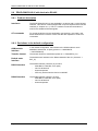
Introduction
1 Introduction
Purpose of the
device
ZDUE-GSM-PLUS-IV, ZDUE-GPRS-PLUS-IV and ZDUE-LAN-PLUS-IV are
meter data transfer devices. They serve to perform the remote readout and
remote monitoring of electricity, heat, gas and water meters with an interface
in accordance with DIN EN62056-21 (formerly: DIN EN61107 and IEC 1107).
The ZDUE devices are designed in such a way that the communication with
the connected meter is identical, e.g. the RS-232 interface of the ZDUEGPRS-PLUS-IV is identical to the RS-232 interface of the ZDUE-LAN-PLUSIV.
Differences between the devices exist mainly concerning the communication
networks used and the different connection options and settings and/or
setting options due to the different communication networks.
The data (remote readout and remote monitoring) are transmitted via:
a common GSM network (ZDUE-GSM-PLUS-IV)
a common GPRS network (ZDUE-GPRS-PLUS-IV)
an Intranet (LAN) or Internet (ZDUE-LAN-PLUS-IV).
This manual starts with instructions on the ZDUE-GSM-PLUS-IV.
Information on the ZDUE-GSM-PLUS-IV with 4-wire RS-485, the ZDUEGPRS-PLUS-IV and the ZDUE-LAN-PLUS-IV - connection options,
parameters etc. that differ from and/or are additional to those of the ZDUEGSM-PLUS-IV - follows thereafter (see ZDUE-GSM-PLUS-IV with the 4-wire
RS-485, ZDUE-GPRS-PLUS-IV and ZDUE-LAN-PLUS-IV).
ZDUE-GSM-PLUS-IV / ZDUE-GPRS-PLUS-IV / ZDUE-LAN-PLUS-IV
Page 7 of 92
ZDUE-GSM-PLUS-IV
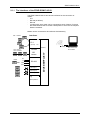
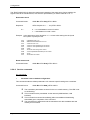
2 ZDUE-GSM-PLUS-IV
Overview
With ZDUE-GSM-PLUS-IV the data transfer for remote readout and remote
monitoring takes place via one of the standard GSM networks.
Meter
Modem
ZDUE-GSM-PLUS-IV
Control center
with
communication
software
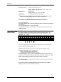
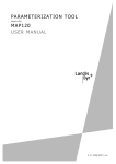
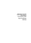
The ZDUE-GSM-PLUS-IV has the following interfaces for the connection of
meters: CL1, RS-232, RS-485 (or M-Bus) and 3 pulse inputs. The maximum
permissible number of meters can be connected simultaneously to each of
the interfaces.
For the remote readout of meters by the control centre the ZDUE-GSMPLUS-IV can connect all the connected meters successively to the control
centre during a single connection, as well as allowing the load profile of the
pulse inputs to be read out. The modem of the ZDUE-GSM-PLUS-IV works
transparently.
How does it work?
The integrated modem of the ZDUE-GSM-PLUS-IV takes data calls from the
GSM network that have been initiated from the control centre.
The control centre can call
from the GSM network via a GSM modem (up to 9600 bps)
from the fixed network via an analogue modem (up to V.32; 9600 bps)
from the fixed network via an ISDN terminal (V.110).
When called, the ZDUE-GSM-PLUS-IV reacts to the telegrams sent by the
control centre as follows:
It connects to the meters that are connected to its interfaces (CL1,
RS-232, RS-485 (or M-Bus)).
It connects to the stored load profile in order to transfer it to the control
centre. The load profile records the consumption data of the meters that
are connected to the pulse inputs of the ZDUE-GSM-PLUS-IV.
It receives parameter commands and carries them out.
Page 8 of 92
ZDUE-GSM-PLUS-IV / ZDUE-GPRS-PLUS-IV / ZDUE-LAN-PLUS-IV
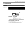
ZDUE-GSM-PLUS-IV
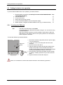
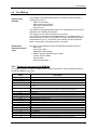
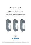
2.1.1 The interfaces of the ZDUE-GSM-PLUS-IV
The ZDUE-GSM-PLUS-IV has various interfaces for the connection of
meters:
CL1
RS-485 (or M-Bus)
RS-232
3 pulse inputs. One meter can be connected to each of these. For these
the ZDUE-GSM-PLUS-IV creates a load profile in which the consumption
data are recorded.
Meters can be connected to all interfaces simultaneously.
Interfaces
max. 4 meters
CL0
CL1
(20 mA)
CS
Modem
OR
M-Bus
1 meter
Rx
Tx
GND
RS-232
DTR
Pulse input 1
Pulse input 2
Control centre
with communication software
ZDUE-GSM-PLUS-IV
RS-485
max. 1000 m
max. 32 meters
Modem
Pulse input 3
Log
GSM operation
ZDUE-GSM-PLUS-IV / ZDUE-GPRS-PLUS-IV / ZDUE-LAN-PLUS-IV
Seite 9 von 92
ZDUE-GSM-PLUS-IV
2.1.2 Access protection
Access protection The ZDUE-GSM-PLUS-IV can be configured so that it accepts calls only at
certain times.
... by time windows
and / or
... by password or
password callback
function
A password query can be configured to protect against unauthorised access.
The ZDUE-GSM-PLUS-IV then asks the calling device for the agreed
password that must be transmitted within the preconfigured time (password
timeout). If the password is incorrect or the timeout is exceeded the ZDUEGSM-PLUS-IV closes the connection.
The password callback function can also be activated. This works as follows:
after a successful password check the ZDUE-GSM-PLUS-IV closes the
connection, then itself makes a new connection to the control centre (the
number of which must have been previously configured).
2.1.3 GSM log
The ZDUE-GSM-PLUS-IV keeps a log which records key events and status
changes that occur in
GSM communication
the GSM operating parameters
local communication with the connected meters
special events.
The GSM log can be used to determine error sources.
2.1.4 Real-time clock for time-controlled functions and module reset
The integrated real-time clock contains a calendar that takes the changes in
day, month, year and leap year into consideration - based on a configurable
state table which is valid for 10 years.
The clock is used for time-controlled functions:
correct storage of the load profile of the meters connected to the pulse
inputs
for access protection by time windows (see above)
regular reset of the GSM module.
The power reserve of the clock bridges a period of up to 2 days during a
power failure (buffering through supercap).
2.1.5 Configuration (parameterisation) and firmware update
Configuration by
parameterisation
Firmware update
Page 10 of 92
Configuration is done using the configuration software, which transmits
parameterisation commands to the ZDUE-GSM-PLUS-IV.
The parameterisation commands can be transmitted to the ZDUE-GSMPLUS-IV via the GSM network (remote configuration) or direct via the RS232 interface (local configuration).
A firmware update can be made via the GSM network using the configuration
software. It is also possible to load new firmware into the device from a
computer that is locally connected direct to the RS-232 interface of the
ZDUE-GSM-PLUS-IV.
ZDUE-GSM-PLUS-IV / ZDUE-GPRS-PLUS-IV / ZDUE-LAN-PLUS-IV
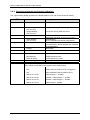
Operating elements and function indicators
2.2
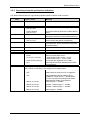
Operating elements and function indicators
The ZDUE-GSM-PLUS-IV has no manual operating elements such as switches or buttons.
Communication with the device takes place exclusively via software command.
To monitor the operating status the device is fitted with 4 LEDs. These serve to indicate the currently
active functions and the current status.
LED
Colour / action
Meaning
Power
Green
Power is on
Status
Red flashing
(0.5 / 0.5 sec)
Orange flashing
(0.5 / 0.5 sec)
Red
PIN / SIM error (no SIM or wrong PIN)
Connection build-up (GSM) active
Orange
Malfunction
(parameter checksum wrong, Data Flash error).
Reinitialisation
(device works with default configuration).
Normal operation
(no malfunction, device works with customised
parameterisation).
Boot phase
Off
No communication (meter/GSM interface)
Green
(on for min. 0.25 sec)
Serial communication active:
- data transfer control centre -> meter
- data transfer meter -> control centre
Green flashing
(0.5 / 0.5 sec)
Green
Communication
GSM status
Beginning of display:
When mobile is switched on and logged into the GSM network.
Off
GSM module off or not logged in.
On
CSD connect
flashes 1x in 2 sec
field strength <= -98 dBm
flashes 2x in 2 sec
-98 dBm < field strength <= -83 dBm
flashes 3x in 2 sec
-83 dBm < field strength <= -68 dBm
LED flashes 4x in 2 sec
field strength > -68 dBm
ZDUE-GSM-PLUS-IV / ZDUE-GPRS-PLUS-IV / ZDUE-LAN-PLUS-IV
Seite 11 von 92
Putting the device into operation
2.3
Putting the device into operation
To put the ZDUE-GSM-PLUS-IV into operation, proceed as follows:
1. Read the safety precautions (see Safety Precautions ZDUE-GSM-PLUS-IV Page
/ ZDUE-GPRS-PLUS-IV)
2. Insert the SIM card
12
3. Connect the meters
13
4. Attach and connect the antenna
15
5. Connect the ZDUE-GSM-PLUS-IV to the power supply
15
6. Where required, configure the ZDUE-GSM-PLUS-IV (e.g. set date and time)
16
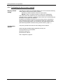
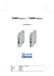
2.3.1 Inserting the SIM card
PIN
The PIN on the SIM card must be 0000.
If your SIM card has a different PIN, please change it. You can do this using
a mobile telephone.
With some network operators it is also possible to deactivate the SIM card
PIN request. In this case the PIN can be anything because it is deactivated
and the request is irrelevant.
To insert the SIM card, proceed as follows:
SIM card
holder
1. Disconnect the device (all poles) from the power supply
if it is connected to it.
2. Loosen the screw of the clamp lid and remove the
clamp lid.
3. Remove the lid of the device.
4. Open the SIM card holder and slide the SIM card into
the flap of the holder. When the SIM card holder is
closed the gold-plated contacts of the SIM card must be
touching the gold-plated contacts of the holder.
5. Close the flap of the SIM card holder and lock the flap
by sliding it carefully upwards until you feel it click into
place.
6. Replace the device lid and the clamp lid.
Under no circumstances must the SIM card be inserted or removed during operation!
Page 12 of 92
ZDUE-GSM-PLUS-IV / ZDUE-GPRS-PLUS-IV / ZDUE-LAN-PLUS-IV
Putting the device into operation
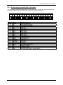
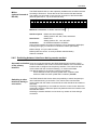
2.3.2 Screw-clamp terminal block connections
The connection of the ZDUE-GSM-PLUS-IV to the power supply and the connection of the meters to
the ZDUE-GSM-PLUS-IV are made via the 18-pin screw-clamp terminal block.
L1
PIN No.
1
2
3
4
5
6
7
8
9
10
11
12
13
14
15
16
17
18
N
LP1- LP1+ LP2- LP2+ LP3- LP3+ RTX- RTX+ RT-
Signal
L1
N
LP1LP1+
LP2LP2+
LP3LP3+
RTXRTX+
RT-/MXRT+/MX+
GND
Tx
Rx
DTR
RT+
GND
TX
RX
DTR
Function/comment
Mains voltage connection
Mains voltage connection
Not wired
Pulse input 1 Pulse input 1 +
Pulse input 2 Pulse input 2 +
Pulse input 3 Pulse input 3 +
Current loop CL1 Current loop CL1 +
RS-485 RTRS-485 RT+
Not wired
Signal GND / cable shield
RS-232 Tx (Output)
RS-232 Rx (Input)
RS-232 DTR (to supply a terminal device)
ZDUE-GSM-PLUS-IV / ZDUE-GPRS-PLUS-IV / ZDUE-LAN-PLUS-IV
Seite 13 von 92
Putting the device into operation
2.3.2.1 Connecting meters
The meter interfaces of the ZDUE-GSM-PLUS-IV are listed below. Connect the meters to the terminal
block as illustrated. All interfaces can be used simultaneously.
3 Pulse inputs
For the connection of electricity meters
with pulse outputs. These can be
operated simultaneously.
The pulses of the meters are counted by
the ZDUE-GSM-PLUS-IV and stored in a
load profile. This can then be read out
from the control centre via a GSM
connection.
Further information: page 20
CL1 interface
This 20mA current loop interface is for
the connection of meters with current
loops in accordance with DIN EN 6205621.
About 4 meters can be connected to this
interface.
Meter 1
Meter 2
Meter 3
LP1- / LP1+
ZDUE
LP2- / LP2+
LP3- / LP3+
CL1Meter 1
ZDUE
Meter 2
Meter n
CL1+
Meter 1
TX
RX
DTR
Further information: page 18
RS-232 interface
For the connection of a meter with an
interface in accordance with V.24/V.28
A maximum of 1 meter can be connected
to this interface.
ZDUE
GND
Further information: page 19
RS-485 interface
For the connection of meters with an
RS485 interface.
A maximum of 32 transceivers (meters)
can be operated at the bus.
Communication takes place on a halfduplex basis.
The bus connection is terminated to
Z=120 Ω (nominal) (RT+ to RT-) and the
cable length limited to 1,000 metres.
The interface is potential separated from
the mains connection.
Meter 1
RTRT+
ZDUE
Meter 2
Meter n
Further information: page 19
Page 14 of 92
ZDUE-GSM-PLUS-IV / ZDUE-GPRS-PLUS-IV / ZDUE-LAN-PLUS-IV
Putting the device into operation
M-Bus interface (optional instead of RS-485)
This serves to connect meters with an MBus interface. A maximum of 25 M-Bus
standard loads can be operated.
Communication takes place on a halfduplex basis.
Further information: page 19
MXMX+
Meter 1
ZDUE
Meter 2
Meter n
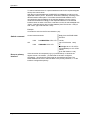
2.3.2.2 Connecting the ZDUE-GSM-PLUS-IV to the power supply
The connection to the supply voltage is made via clamps L1 and N of the terminal block. These
clamps are designed for cables with a cross-section of up to 1.5 mm².
L1
N
LP1- LP1+ LP2- LP2+ LP3- LP3+ RTX- RTX+ RT-
RT+
GND
TX
RX
DTR
The ZDUE-GSM-PLUS-IV can be operated with either alternating current or direct current. The device
complies with Protection Class 2. The supply of the interfaces is galvanically separated from the
electronics.
Supply voltage
AC voltage:
Nominal values
Maximum values
100VAC to 230VAC without
76VAC to 253VAC
switching (50/60 Hz)
DC voltage (protected against
60VDC to 100VDC without
54VDC to 110VDC
polarity reversal):
switching
The device complies with Protection Class 2. The power supply of the interfaces is separated
galvanically from the electronics.
2.3.3 Attaching and connecting the antenna
Antenna connector
The antenna is connected to the FME antenna
socket.
The antenna should be installed so that sufficient
signal quality is attained. Make sure that there are
no large metal objects near the antenna (e.g.
reinforced concrete) as these have a negative
effect on signal quality.
When an external antenna is installed
outdoors it must be grounded against
lightning on the installation bracket. This must
be done by a qualified technician.
Please consult the instructions included with your
antenna.
ZDUE-GSM-PLUS-IV / ZDUE-GPRS-PLUS-IV / ZDUE-LAN-PLUS-IV
Seite 15 von 92
Putting the device into operation
2.3.4 Configuring the device where required
Delivery default
setting
Configuration
options
The default pre-setting of the ZDUE-GSM-PLUS-IV is such that the following
meter interface serves as the primary interface:
CL1 during a GSM connection with the control centre
RS-232 if there is no GSM connection (to the local configuration)
This means that meter readouts by the control centre are automatically
directed to the CL1 interface so that the control centre can communicate with
the meters connected to this interface.
During the same GSM connection the control centre can be connected to
other interfaces and the meters connected there when the control centre
sends a corresponding switch-over command to the ZDUE-GSM-PLUS-IV.
(See Switching between interfaces during remote readout, page 21.)
The primary interface and various other settings can be altered.
Other important possible settings regarding security are:
access protection by time window
password request and
password with callback
See Configuration, page 25.
Page 16 of 92
ZDUE-GSM-PLUS-IV / ZDUE-GPRS-PLUS-IV / ZDUE-LAN-PLUS-IV
Operation
2.4
Operation
2.4.1 The GSM interface
Properties
Communication with the GSM network takes place via a GSM/GPRS module
from Sagem. Data transfer takes place according to the following standards:
GSM Rec. 7.02 asynchronous, RLP in acc. with GSM Rec. 4.22,
ISDN type V.110, analogue modem type V.32
Default setting for the internal GSM module interface:
Transmission speed: 19200 Bps
Data format: 7E1 (optional 8N1 configurable)
Flow control: Hardware (RTS/CTS)
The device can be set up for communication via GPRS.
2.4.2 Time management with real-time clock
The ZDUE-GSM-PLUS-IV has a real-time clock. A supercap bridges a power
failure of up to 2 days.
The real-time clock contains a calendar that takes the changes in day,
month, year and leap year into consideration. Automatic switching between
summer and winter time is based on a configurable state table which is valid
for 10 years.
The control centre has to set the time when putting the device into operation
and also after a power failure of 2 days or longer.
The clock is used for
correct recording of the load profile,
time-controlled call acceptance, if activated,
periodic resets of the GSM module (default: 1xdaily, 23 h),
time stamp in the GSM logbook.
2.4.3 Controlling communication
Control properties
Detection
of the end of a
communication
cycle
The ZDUE-GSM-PLUS-IV controls communication between the control
centre and the meters connected to the ZDUE-GSM-PLUS-IV in accordance
with Protocol EN 62056-21 (Annex A):
- in mode A/C,
- in data readout and programming mode,
- including data backup (reception) and acknowledgement.
The start baud rate and the data format can be adjusted for the following
interfaces: CL1 (Current Loop Interface), RS-232, RS-485/M-Bus
In ModeC operation, the baud rate is switched according to the baud rate
ID received in the acknowledge telegram from the control centre.
During the data readout the end of a communication cycle is detected when
- no meter data are received for >= 3 seconds (mode A/C timeout)
- the sequence ‘CR LF ETX‘ is detected (mode C normal end)
In programming mode the end of a communication cycle is detected when
- a ‘break‘ telegram is recognised (mode A/C break).
Once a communication cycle is completed the connection is closed and the
baud rate of the serial interface driver of the meter interfaces is reset to the
parameterised start value.
ZDUE-GSM-PLUS-IV / ZDUE-GPRS-PLUS-IV / ZDUE-LAN-PLUS-IV
Seite 17 von 92
Operation
Normal connection
release
Connection release after transfer timeout:
The ZDUE-GSM-PLUS-IV ends a normal data connection following expiry of
the transfer timeout. This means that if no data transfer takes place between
the control centre and the ZDUE-GSM-PLUS-IV or the meters connected to
the ZDUE-GSM-PLUS-IV during an existing connection within the fixed
timeout (standard: 20 seconds), the ZDUE-GSM-PLUS-IV closes the
connection.
Connection release by the control centre:
The control centre can terminate the connection at any time.
Connection
terminated due to
errors
If a connection is terminated during a meter readout due to errors (e.g.
network failure), the ZDUE-GSM-PLUS-IV ends data output by means of a
'break' as described in the VDEW specifications.
If a meter does not support this feature it may happen that, after the
connection has been re-established, the control centre wishes to
communicate with an external meter, but this meter is still in 'data transfer'
status. In this case, the request telegram for the (one) external meter is
rejected and the communication cycle is ended by timeout.
2.4.4 Meter interfaces
CL1
The interface CL1 corresponds to the current loop interface in accordance
with DIN EN 62056-21.
It is an active 20 mA interface with a 2-wire connection via the clamps RTXand RTX+ (clamps 10 and 11) on the terminal block.
L1
N
LP1- LP1+ LP2- LP2+ LP3- LP3+ RTX RTX RT- RT+
GND TX
RX DTR
Maximum connectable: 4 meters
The interface is separated from the modem via an optocoupler.
Default: 7E1
Setting options: 7E1, 7O1, 8N1, 8E1
No hardware/software handshake.
Data format:
Handshake:
Default: 300 baud (mode C)
Setting options: 300, 600, 1200, 2400, 4800, 9600,
19200 baud.
When communicating with the connected meters the following methods are
possible:
Interface speed:
Fixed baud rate
The speed is fixed to a particular value by parameterisation. The
communicating meter and the control centre connected via modem
exchange data at the selected speed, i.e. the ZDUE-GSM-PLUS-IV
works transparently. The speed is the same as or slower than the GSM
speed (9600bps).
Variable baud rate
Corresponds to baud rate switching in accordance with Mode C as per
Page 18 of 92
ZDUE-GSM-PLUS-IV / ZDUE-GPRS-PLUS-IV / ZDUE-LAN-PLUS-IV
Operation
DIN EN 62056-21.
The starting speed is 300 baud. The speed is increased when the
communicating meter requests this from the CL1 interface and the
interface confirms the requested baud rate. If there is no confirmation,
communication is continued at the current speed.
The speed of the meter interface should not exceed the speed of the
GSM connection (9600bps) as this could cause transfer problems.
During a meter readout all the characters sent to the meter are sent back as
an echo via the CL1 interface. These characters are normally transferred to
the superordinated system. The echo is suppressed by the modem.
RS-485
The meters are connected to the clamps RT- and RT+ (clamps 12, 13) of the
terminal block via a 2-wire bus connection.
L1
N
LP1- LP1+ LP2- LP2+ LP3- LP3+ RTX RTX RT- RT+
GND TX
RX DTR
Maximum connectable: 32 meters
Interface speed:
Default: 300 baud (mode C)
Data format:
Setting options: 300, 600, 1200, 2400, 4800, 9600,
19200 baud
Default: 7E1
Setting options: 7E1, 7O1, 8N1, 8E1
No hardware/software handshake
Handshake
The speed of the meter interface should not exceed the speed of the
GSM connection (9600bps) as this could cause data loss.
Communication can take place as with the CL1 interface.
Communication takes place on a half-duplex basis.
The bus connection has been terminated to 120 ohms and the cable length
limited to 1,000 metres.
The interface is potential separated from the mains connection.
RS-232
The interface corresponds to the V.24 / V.28 specification.
A meter is connected to the RS-232 interface by a 3 or 4-wire connection via
the clamps RX, TX, GND and DTR (clamps 15, 16, 17, 18) of the terminal
block.
L1
N
LP1- LP1 LP2- LP2 LP3- LP3 RTX RTX RT- RT+
GND TX
RX DTR
Maximum connectable: 1 meter
Use a shielded cable. The connection of the signal ground and of the cable
shield is made at GND, the cores for the reception data at RX, for
transmission at TX.
In addition, the ZDUE-GSM-PLUS-IV can signal to the connected meter via
the signal DTR whether it is connected to the control centre.
ZDUE-GSM-PLUS-IV / ZDUE-GPRS-PLUS-IV / ZDUE-LAN-PLUS-IV
Seite 19 von 92
Operation
Interface speed:
Default: 300 baud (mode C)
Data format:
Setting options: 300, 600, 1200, 2400, 4800, 9600,
19200, 38400, 57600 baud
Default: 7E1
Setting options: 7E1, 7O1, 8N1, 8E1
No hardware/software handshake
Handshake:
The speed of the meter interface should not exceed the speed of the
GSM connection (9600bps) as this could cause data loss.
The interface is potential separated from the mains connection.
Local configuration:
The ZDUE-GSM-PLUS-IV can be configured using a computer connected to
this interface.
The appropriate setting is: 19200 baud, 8N1.
The RS-232 interface is automatically set to these values when there is no
GSM connection.
Pulse inputs (load
profile inputs)
The pulse inputs correspond to DIN EN 62053-31 Class B.
The ZDUE-GSM-PLUS-IV has 3 pulse inputs (load profile inputs). The
connection is made via the clamps LP1-,LP1+; LP2-, LP2+; LP3-,LP3+
(clamps 4, 5; 6, 7; 8, 9).
L1
N
LP1- LP1+ LP2- LP2+ LP3- LP3+ RTX RTX RT- RT+
GND TX
RX DTR
The incoming pulses are recorded in the load profile (see Load profile for
meters at the pulse inputs, page 23).
Different kinds of pulse sources can be used as the following can be
configured separately for each pulse input:
active pulse edge (rising, falling) and
minimum pulse duration (10ms to 150ms).
If the pulse edge is 'rising', pulse counting takes place upon closure of the
electrical circuit through the pulse output. With an active, 'falling' pulse edge,
pulse counting takes place when the electrical circuit is opened.
The pulse duration setting should be at least 20 ms less than the actual
pulse duration.
The pulse inputs are potential separated from the mains and, all taken
together, have a common reference potential.
Page 20 of 92
ZDUE-GSM-PLUS-IV / ZDUE-GPRS-PLUS-IV / ZDUE-LAN-PLUS-IV
Operation
The ZDUE-GSM-PLUS-IV is also optionally available with an M-Bus interface
M-Bus
according to EN1434-3. These devices do not have the RS-485 interface.
(optional instead of
The meters are connected via a 2-wire bus connection to the MX and MX+
RS-485)
terminals (terminal 12, 13) on the terminal strip.
L1
N
LP1- LP1+ LP2- LP2+ LP3- LP3+ RTX- RTX+ MX- MX+
GND TX
RX DTR
Maximum connection: 25 M-Bus standard loads
Interface speed:
Default: 300 baud (ModeC)
Setting options: 300, 600, 1200, 2400 baud
Default: 7E1
Data format:
Setting options: 7E1, 7O1, 8N1, 8E1
No hardware/software handshake
Handshake
Active 2-wire interface according to EN1434-3 up to 2400 baud, half-duplex,
including the supply of a maximum of 25 M-Bus meters (Minimaster)
M-Bus voltage: 31V (core without load)
M-Bus quiescent current: 37.5mA (25 M-Bus standard loads)
Galvanic insulation
2.4.5 Switching between interfaces during remote readout
Automatic activation Once the connection between the ZDUE-GSM-PLUS-IV and the control
centre is established, the modem of the ZDUE-GSM-PLUS-IV activates the
of the primary
interface that is configured as the primary interface. The control can then
interface
communicate with the connected meter(s), i.e. read out their data.
The default setting for the primary interface is as follows:
with a GSM connection (Connect) (GSM online condition): CL1
without a GSM connection (GSM offline condition): RS-232
Switching to other
interfaces during a
connection
The ZDUE-GSM-PLUS-IV also offers the possibility to switch temporarily to
other interfaces during a connection. The control centre can then also
communicate with the meters connected to the other interfaces and read out
their data.
Switching is triggered by a command sent from the control centre. When the
command is sent the parameters previously determined for the interface now
selected take effect.
Switching to another interface can be done any number of times during a
connection.
ZDUE-GSM-PLUS-IV / ZDUE-GPRS-PLUS-IV / ZDUE-LAN-PLUS-IV
Seite 21 von 92
Operation
To switch interfaces there is a special address mode for the request telegram
sent by the control centre.
With the two special addresses COMPORT# and DM600# as well as of the
appended number (1=CL1, 2=RS-232, 3=RS-485, 4=M-Bus), switching to the
desired interface takes place. This means that the ZDUE-GSM-PLUS-IV
recognises this special address in the request telegram from the control
centre and switches accordingly to the requested interface. If the desired
interface does not exist or if there is a transfer error this is acknowledged with
<NAK>, otherwise with a dummy billing dataset (from FW-Version 1.205) or
with <ACK> (up to FW-Version 1.204).
Example:
Command to switch to the RS-232 interface (=2):
Switch command
Control centre transmits:
HHU
Reply from the ZDUE-GSMPLUS-IV:
/?COMPORT#2!<CR><LF>
<ACK>
(up to FW-Version 1.204)
HHU /?DM600#2!<CR><LF>
or
/ABB5\@4.20<cr><lf><STX>
F.F(00000000)<cr><lf><ETX>
<BCC>
(from FW-Version 1.205)
If the connection is interrupted (e.g. by a power failure) or closed in the
regular manner, the modem - provided that it has been configured
accordingly - can transmit a break signal to the interface last used. The
ZDUE-GSM-PLUS-IV then switches back to the primary interface, i.e. to the
interface configured as primary.
OR
Reset to primary
interface
Page 22 of 92
ZDUE-GSM-PLUS-IV / ZDUE-GPRS-PLUS-IV / ZDUE-LAN-PLUS-IV
Operation
2.4.6 Load profile for meters at the pulse inputs
For the three pulse inputs the ZDUE-GSM-PLUS-IV records an internal load
profile indicating the consumption measured by the meter concerned. The
memory for the load profile is implemented as a circulating memory, i.e.
when the end of the memory is reached the oldest load profile entry is
overwritten.
The recording of the load profile and the load profile status takes place in
accordance with the parameterised measurement period pattern. The control
centre provides the measurement period values for the readout in VDEW
format (for 3 channels in each case).
The following parameters can be set:
- Pulse duration 10-150ms
- Flank rising or falling
- Measurement period duration: 1, 5, 15, 30, 60 minutes
- ID and unit in acc. with EDIS
- Medium acc. with EDIS (ZDUE-GSM-PLUS-IV from FW-Version 1.210 /
07.12.2004)
Load profile
specifications
Protocol depth:
min. 40 days with 15-minute measurement period,
No. of channels: 3
Meter width:
6 decades (without decimal places)
Meter mode:
feed
In addition to the measuring values a status byte is stored at every
measuring point in the circulating memory in which the following events
relevant to the load profile are recorded:
- time switching (summer winter time (standard time))
- measurement period changed (deletes the entire load profile)
- incomplete measurement period
- power failure (when power returns all affected entries are completed and
the current measurement period marked accordingly - see page 23)
- time reset.
The bit coding of the status byte is described in the section Status
commands, page 45.
2.4.7 Effects on the load profile of power failure or change in time or
measurement period
Power failure
In the event of a power failure the current measurement period is not
completed. When power returns the measurement period interrupted by the
power failure is continued and completed by the measurement period pattern
determined by the device's clock. The meter values attained during the
measurement period up to the power failure are lost, as are meter pulses
during the power failure. At the first measuring point after power returns only
the meter pulses between the return of power and the measuring point are
stored. Immediately after power returns and at the first measuring point after
this a timestamp is entered in the load profile.
ZDUE-GSM-PLUS-IV / ZDUE-GPRS-PLUS-IV / ZDUE-LAN-PLUS-IV
Seite 23 von 92
Operation
In the event of a power failure between 2 measuring points the current
measurement period is marked with the status entry ‘Power failure‘.
In the event of a power failure skipping one or more measuring points no
measurement periods are entered subsequently. The current measurement
period (from return of power to measuring point) is given the status entry
‘Power failure‘.
Setting the clock
Putting the clock forward/back without exceeding a measuring point:
If the device's clock is changed (put forward/back) without exceeding a
measuring point, this has no influence on the measurement value recording.
At the next measuring point the status entry 'Time reset' is recorded.
Putting the clock forward/back in excess of one measuring point:
Forward:
The device's clock is, for example, put forward in excess of one
measuring point from 13:12:10 to 13:16:00 given a 15-minute
measurement period.
A recording with a new date/time (i.e. 13:16:00 here) is immediately prompted
and given the status entry 'Time reset' in the load profile. The next recording
then takes place in the measurement period raster, i.e. at 13:30:00.
Back:
The device's clock is, for example, put back by more than one
measuring point from 11:02:05 to 10:59:00 given a 15-minute
measurement period.
The last entry in the circulating memory (11:00:00) is deleted, and the meter
values of this entry are added to the current values and registered at the next
measuring point (11:00:00) with the entry 'Time reset' in the load profile
memory.
Putting the clock forward/back in excess of several measuring points:
Example:
The device's clock is put forward or back in excess of several
measuring points (e.g. from 13:12.10 to 13:32:00 given a 15-minute
measurement period).
When putting the clock forward or back in excess of several measuring points,
no changes are made in the circulating memory. The next recording (here:
13:45:00) is made with the status entry ‘Time reset‘.
Changing between Change summer time winter time
summer and winter In the course of the automatic change from summer to winter time (standard
time) - the clock is put back by 1 hour - the measurement period which ends at
time
the time of the change is given the status entry ‘Time change‘.
Measurement period sequence:
02:00 02:15 02:30 02:45 02:00 02:15 02:30 02:45 03:00.
Change winter time summer time
In the course of the automatic change from summer to standard (= winter)
time - the clock is put forward by 1 hour - the measurement period which ends
at the time of the change is given the status entry ‘Time change‘ (03:00). No
measurement periods are entered subsequently (as with status 'Power
failure').
Measurement period sequence:
01:30 01:45 03:00 03:15 03:30.
Measurement
period sequence
Page 24 of 92
Altering the measurement period duration automatically results in the deletion
of the entire load profile and meter value registers.
ZDUE-GSM-PLUS-IV / ZDUE-GPRS-PLUS-IV / ZDUE-LAN-PLUS-IV
Configuration
2.5
Configuration
The most important Security settings
Time window
configurable
Password
settings and
Password callback function
functions
Device time
Primary interface
Data format and transfer rates of the different interfaces
Module reset
2.5.1 Configuration by parameterisation
Configuration is done with the software that is used to operate the control
centres. Parameter commands are transferred to the ZDUE-GSM-PLUS-IV
using this software.
The software commands are described on page 29 ff.
The parameter commands can be transferred to the ZDUE-GSM-PLUS-IV
via the GSM network (remote configuration) or direct via the RS-232 interface
(local configuration).
Remote configuration is performed by the control centre which sends
Remote
parameter commands to the ZDUE-GSM-PLUS-IV via the GSM network.
configuration via the Transfer takes place in accordance with DIN EN 62056-21 using a BCC
GSM network
protocol. The parameter commands must be sent explicitly to the address of
the ZDUE-GSM-PLUS-IV.
The default device address is as follows: 99999999
The device address is configurable. It has 16 digits; numbers and letters are
permissible.
Local configuration The device can also be configured using a computer that is connected direct
via its COM port to the RS-232 interface of the ZDUE-GSM-PLUS-IV.
Prerequisite:
There is no active GSM connection between the ZDUEGSM-PLUS-IV and the control centre.
GSM offline status: RS-232 interface settings
As soon as there is no active GSM connection the RS-232 interface is set by
default to the following settings:
19200 baud
8 data bits, no parity, 1 stop bit
Make sure that the settings of the COM port being used on the connected
configuration computer correspond to the above settings and switch off any
flow control (hardware (RTS/CTS), XON-XOFF).
When the computer connected to the RS-232 interface sends request
telegrams with the device address of the ZDUE-GSM-PLUS-IV (default:
99999999), the ZDUE-GSM-PLUS-IV reacts exactly as if it were receiving the
ZDUE-GSM-PLUS-IV / ZDUE-GPRS-PLUS-IV / ZDUE-LAN-PLUS-IV
Seite 25 von 92
Configuration
request telegrams from the remote control centre via the GSM network.
During local configuration via the RS-232 interface the ZDUE-GSM-PLUS-IV
will not accept calls from the GSM network.
GSM online status: RS-232 interface settings
As soon as a GSM connection is established the RS-232 interface is set by
default to the following settings:
19200 baud
7 data bits, even parity, 1 stop bit
These settings remain in effect for the duration of the GSM connection.
The settings of the RS-232 interface for GSM online status are
configurable.
2.5.2 Saving the configuration in the file para.ini
All the settings of the ZDUE-GSM-PLUS-IV are stored in the file para.ini.
The parameter file para.ini illustrated below shows
the adjustable parameters (settings)
their explanations and
their possible values.
The parameter file, para.ini, is divided into sections ([SEKTION]). The parameter classes in
communication according to DIN EN 62056-21 on these sections is illustration in the table on page 29.
The parameter classes (C51 to C58) are to be indicated in parameter commands.
[MOBILE_CONFIG]
SIMPIN=pin_number
RESTART_TIME=hh:mm
RESTART_IV=hh
BAUDRATE=9600 | 19200 | 38400 | 57600
DATABITS=7 | 8
STOPBITS=1
PARITY=NO | EVEN | ODD
;For SIM cards with activated PIN function the PIN number
;must be
;entered here (max. 9 digits)
;GSM Location Area Identification Number of the network
;operator
;under which the module is to book itself in (e.g. '26201‘ for
;D1)
;Interval [05..99 minutes] that determines how often an
attempt is
;made to reset the operator (if parameterised and if the
;current operator differs from the parameterised operator).
;Bearer service type (AT+CBST=), default: 7 (9600 bps
;(V.32)):
; 0 = autobauding
; 7 = 9600 bit/sec (V.32)
; 14 = 14400 bit/sec (V.34)
; 71 = 9600 bit/sec (V.110)
; 75 = 14400 bit/sec (V.110)
;Start time for module reset (default: 23:00)
;Interval for module reset (01 .. 48 hours, default: 24 hours)
;Baud rate of the serial mobile interface driver (max. 6 digits)
;No. of data bits (max. 1 digit and only numbers permitted)
;No. of stop bits (only ‘1‘ permitted)
;Parity (only NO, EVEN or ODD permitted)
CCFC_QUERY=YES | NO
;Status query Perform call forwarding
OPERATOR=network_operator
OP_SET_DELAY=operator_select_interval
BEARER_SERVICE=0 | 7 | 14 | 71 | 75
Internally generated entries:
SIMSTATE=SIM_PROBLEM | SIM_ERROR
Page 26 of 92
;Entry is only created by the mobile handler when the first
;(SIM_PROBLEM) or second (SIM_ERROR) PIN handoff to
;the mobile is acknowledged as an ERROR.
ZDUE-GSM-PLUS-IV / ZDUE-GPRS-PLUS-IV / ZDUE-LAN-PLUS-IV
Configuration
NEW_SIMPIN=new_pin_number
STEADY_IMSI_CHECK=mode
[GSMLOG_CONFIG]
KENNZIFFER=50..98
;Entry is only created by the application when a new PIN is
;to be set in the mobile. Mobile handler checks after each
;disconnect (NO CARRIER) for this entry and
;changes the PIN in the mobile. After successful execution,
;parameter SIMPIN is set on the new PIN and the parameter
;NEW_SIMPIN is deleted.
;Controls the functionality of the cyclical (per second) IMSI
;poll ;(AT+CIMI)
ENABLED=YES | NO
TIMEOUT=2..15
;Index no. of the GSM logbook in communications
;(default: '98')
;Record in the GSM logbook active/inactive
;Timeout to generate cyclical GSM logbook entries [min.]
[CSD_CONFIG]
CSD_DIAL_STRING= number
;CSD-Parameter
;Control centre number (max. 30 characters)
[LS]
PROTECTION= NO | PASSWORD | CALLBACK
;Control centre parameters
PASSWORD=control_centre_password
TRANSFER_TO=10 .. 99
[DEVICE_CONFIG]
IEC_ADR=iec_address_ZDUE
IEC_IDENT=identification_ZDUE
IEC_SET_PW=set_password_ZDUE
IEC_TA=2 ... 20
IEC_TR=2 ... 20
EXT_IF=CL1 | RS232 | RS485 | M_BUS
EVU_IDENT=property_no
[CLOCK_CONFIG]
SOWI_TIME1=date_time
SOWI_TIME2=date_time
SOWI_TIME3=date_time
:
= :
SOWI_TIME20=date_time
TIME_WINDOW=hh:mm hh:mm
[RS232D]
BAUDRATE=300 ...115200
DATABITS=7 | 8
STOPBITS=1 | 2
PARITY=NO | EVEN | ODD
BREAK= YES | NO
BREAK_TIME=20...3000
MODE=MODEC | TRANSPARENT
DTR_MODE=ALWAYS | ONLINE
[CL1]
BAUDRATE=300 ...19200
DATABITS=7 | 8
;NO: no password protection, PASSWORD: password
;callback, CALLBACK: password with callback
;Control centre password (max. 16 characters)
;If inactivity for > timeout [sec] => close connection
;(from V1.207 in area 10 .. 99 sec adjustable, formerly to
;max. ;60sec)
;IEC address of ZDUE (max. 16 characters,
;def.: ‘99999999‘)
;Device identification of ZDUE
;(max. 16 characters, def.: TBD)
;Set password of ZDUE (max. 16 characters,
;def.: ‘00000000‘)
;ta in acc. with EN 62056-21 (default: 9 [sec],
;ZDUE-GSM-PLUS-IV from V1.210 : 15 sec).
;tr in acc. with EN 62056-21 (default: 9 [sec] ],
;ZDUE-GSM-PLUS-IV from V1.210 : 15 sec).
;Determination of external interface (meter interface)
;Property no of the ZDUE-GSM-PLUS-IV for invoicing data
;record (ZDUE-GSM-PLUS-IV from V1.210)
;Next switch time summer/winter time
; e.g.: SOWI_TIME1=28.10.2002 03:00
; 2nd switch time summer/winter time (3,03,30,2)
; 3rd switch time summer/winter time (3,10,26,3)
;20th switch time summer/winter time (12,03,25,2)
;Call acceptance time window, e.g. 03:00 to 05:40
;RS232 section for ZDUE
;Start baud rate in acc. with EN 62056-21 (ModeC)
;No. of data bits (max. 1 digit and only numbers permitted)
;No. of stop bits (max. 1 digit and only numbers permitted)
;Parity (only NO, EVEN or ODD permitted)
;No=do not send physical break in case of GSM disconnect
;Yes=send physical break in case of GSM disconnect
;Duration of physical break in msec (Def.: 300 msec)
;ModeC monitoring (Def.) or direct transparent (without baud
;rate switching)
;DTR-activation: always active | only when device is online
;(Def.)
;Current Loop Interface (active)
;Start baud rate in acc. with EN 62056-21 (ModeC)
;No. of data bits (max. 1 digit and only numbers permitted)
ZDUE-GSM-PLUS-IV / ZDUE-GPRS-PLUS-IV / ZDUE-LAN-PLUS-IV
Seite 27 von 92
Configuration
STOPBITS=1 | 2
PARITY=NO | EVEN | ODD
BREAK= YES | NO
BREAK_TIME=20...3000
MODE=MODEC | TRANSPARENT
[RS485_MBUS]
BAUDRATE=300 ...57600
DATABITS=7 | 8
STOPBITS=1 | 2
PARITY=NO | EVEN | ODD
BREAK= YES | NO
BREAK_TIME=20...3000
MODE=MODEC | TRANSPARENT
[LPRF]
MEASURE_PERIOD=5 | 15 | 30 | 60
ACTIVE_EDGE_LP1=FALL | RISE
ACTIVE_EDGE_LP2=FALL | RISE
ACTIVE_EDGE_LP3=FALL | RISE
ACTIVE_TIME_LP1=10...150
ACTIVE_TIME_LP2=10...150
ACTIVE_TIME_LP3=10...150
EDIS_KZ_LP1=edis_index_no._channel1
EDIS_KZ_LP2=edis_index_no._channel2
EDIS_KZ_LP3=edis_index_no._channel3
EDIS_MWE_LP1=edis_measuring_unit1
EDIS_MWE_LP2=edis_measuring_unit2
EDIS_MWE_LP3=edis_measuring _unit3
MEDIUM_LP1=medium channel 1
MEDIUM_LP2=medium channel 2
MEDIUM_LP3=medium channel 3
LP3_FUNCTION=IMPULS | SYNC
[GENERAL]
PAR_STATUS=DEFAULT | USER
PAR_VERSION=002
SEASON=WINTER | SUMMER
PLATFORM=ZDUE_CSD
Page 28 of 92
;No. of stop bits (max. 1 digit and only numbers permitted)
;Parity (only NO, EVEN or ODD permitted)
;No=do not send physical break in case of GSM disconnect
;Yes=send physical break in case of GSM disconnect (Def.)
;Duration of physical break in msec (Def.: 300 msec)
;ModeC monitoring (Def.) or direct transparent (without baud
;rate switching)
;RS485-/M-Bus Interface
;Start baud rate in acc. with EN 62056-21 (ModeC)
;No. of data bits (max. 1 digit and only numbers permitted)
;No. of stop bits (max. 1 digit and only numbers permitted)
;Parity (only NO, EVEN or ODD permitted)
;No=do not send physical break in case of GSM disconnect
;Yes=send physical break in case of GSM disconnect (Def.)
;Duration of physical break in msec (Def.: 300 msec)
;ModeC monitoring (Def.) or direct transparent (without baud
;rate switching)
;LPRF = Load profile
;Measurement period duration (5 / 15 / 30 / 60 [minutes])
;Active edge LP1
;Active edge LP2
;Active edge LP3
;Minimum pulse duration LP1 (10 ... 150 [msec])
;Minimum pulse duration LP2 (10 ... 150 [msec])
;Minimum pulse duration LP3 (10 ... 150 [msec])
;EDIS index no. channel 1 (LP1) (e.g.: ‘1.5‘, max. 7
;characters)
;EDIS index no. channel 2 (LP2) (e.g.: ‘1.5‘, max. 7
;characters)
;EDIS index no. channel 3 (LP3) (e.g.: ‘1.5‘, max. 7
;characters)
;Measuring unit channel1 (e.g.: ‘kW‘, max. 7 characters)
;Measuring unit channel2 (e.g.: ‘kW‘, max. 7 characters)
;Measuring unit channel 3 (e.g.: ‘kW‘, max. 7 characters)
;Medium for channel (e.g.: '1-', max. 4 characters)
;(ZDUE-GSM-PLUS-IV from V1.210)
; Medium for channel (e.g.: '1-', max. 4 characters)
;(ZDUE-GSM-PLUS-IV from V1.210)
; Medium for channel (e.g.: '1-', max. 4 characters)
;(ZDUE-GSM-PLUS-IV from V1.210)
;LP3 can be used as a pulse input (def.) or as a
;synchronisation input (MP termination)
;System works with default configuration / user
;parameterisation (may only be changed by the system)
;parameter version no.
;Winter/summer time active
;System-dependent parameter (must not be changed)
ZDUE-GSM-PLUS-IV / ZDUE-GPRS-PLUS-IV / ZDUE-LAN-PLUS-IV
Configuration
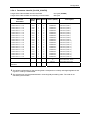
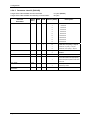
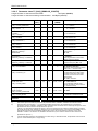
2.5.3 Parameters and classes, class numbers
The following table shows the section, i.e. classes contained in the parameter file para.ini. Numbers
are assigned to these classes and must be included in the parameter commands.
Class
Permitted access
types
(R=Read/W=Write)
[MOBILE_CONFIG]
[CSD_CONFIG]
51
R/W
[LS]
52
R/W
[DEVICE_CONFIG]
53
R/W
[CLOCK_CONFIG]
54
R/W
[RS232D]
55
R/W
[CL1]
56
R/W
[RS485_MBUS]
57
R/W
[LPRF]
58
R/W
[GENERAL]
59
R
Section in ‘para.ini‘
The writing of parameters can only be done by writing a complete class (offset and length must be
given as ‘0000‘).
When extending a class the new parameters must be appended in order to guarantee downward
compatibility.
The parameter checksum in the RAM is checked hourly. If there are checksum deviations in the nonvolatile memory the parameters are reloaded from the non-volatile memory. This check does not take
place during an active communication and is performed, where appropriate, following communication.
A deviation in the checksums is entered in the operating status word (parameter reload from the nonvolatile memory).
Each parameter class embraces a reserved area for possible extensions. Parameter extensions
covered by this reserve area do not result in incompatibility between different firmware versions. If the
space for extensions is not sufficient a new parameter class must be created. This also does not lead
to incompatibility because a command to set/read this new parameter class would be acknowledged
with ERROR by an older firmware version. The reserved parameter areas are filled with ‘0‘ (0x30)
during communication.
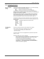
2.5.4 Parameters sorted according to classes; notation
In the following, the parameters are sorted according to classes in a way that corresponds to their
notation in parameter commands. Default configuration: the default configuration is highlighted in
bold face. The terms Offset, RAM, COM and Values (ASCII) require explanation:
Offset
RAM
COM
Values
(ASCII)
Contains the relative address of a parameter within the parameter class with regard
to the RAM structure.
Indicates the memory length required for a parameter in the RAM. With string
parameters the length of the string is always listed as a separate parameter.
Indicates the number of ASCII characters required to signify the parameter during
communication. With strings only the fixed number of ASCII characters determined as
the 'string length' is significant (decimal coded); any unused string area must be filled.
Contains permissible values (areas) for the individual parameters when writing (W1
command) and reading by means of an R3 command.
ZDUE-GSM-PLUS-IV / ZDUE-GPRS-PLUS-IV / ZDUE-LAN-PLUS-IV
Seite 29 von 92
Configuration
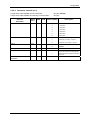
2.5.4.1 Parameter class 51 [Mobile_Config] / [CSD_CONFIG]
Length of the Class 51 data record in the RAM:
Length of the Class 51 data record during communication:
Class 51
Parameter
BAUD RATE
DATA FORMAT
Offset
(hex.)
RAM
COM
0x00
1
1
0x01
1
1
84 bytes (0x0054)
90 bytes
Values (ASCII)
Description
‘5‘
9600 baud
‘6‘
19200 baud
‘7‘
38400 baud
‘8‘
57600 baud
‘9‘
115200 baud
‘0‘
7 data bits, even parity, 1 stop bit
‘1‘
8 data bits, no parity, 1 stop bit
‘2‘
7 data bits, even parity, 1 stop bit
(software emulation via 8N1)
String length SIMPIN
0x02
1
1
‘0‘ .. ‘9‘
SIMPIN
0x03
9
9
Max. 9 numbers
OP_SET_DELAY
0x0C
1
2
‘05‘ .. ‘99‘
[minutes] Interval for module request
‘Operator Select‘, when
parameterised and actual operator
are different.
(Def.: ‘15‘)
String length OPERATOR
0x0D
1
1
‘0‘ .. ‘5‘
String length of network operator ID
(Def.: ‘0‘)
OPERATOR
0x0E
5
5
Max. 5 numbers
BEARER_SERVICE
0x13
1
2
‘00‘, ‘07‘, ‘14‘, ‘71‘,
‘75‘
RESTART_TIME
0x14
2
4
‘0000‘ .. ‘2359‘
Start time for the module reset cycle
(hhmm), default: 23:00
RESTART_IV
0x16
1
2
‘01‘ .. ‘24‘
Interval for the module reset [hours]
default: 24
String length
CSD_DIAL_STRING
0x17
1
2
‘00‘ .. ‘30‘
Length of CSD dial string (control
centre number) (Def.: ‘00‘)
CSD_DIAL_STRING
0x18
30
30
Reserved for additional
parameters
0x3A
26
24
Page 30 of 92
Length of SIMPIN (Def.: ‘4‘)
SIMPIN
(Def.: ‘0000‘)
Network operator ID (Def.: ‘empty ‘)
GSM speed:
00=autobauding,
07=9600bps(V.32),
14=14400bps(V.34),
71=9600bps(V.110),
75=14400bps(V.110)
Max. 30 characters CSD dial string (control centre
'0' to '9', '*', '#', '+' 'A', number) (Def.: ‘empty ‘)
'B' und 'C
TBD
TBD
ZDUE-GSM-PLUS-IV / ZDUE-GPRS-PLUS-IV / ZDUE-LAN-PLUS-IV
Configuration
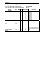
2.5.4.2 Parameter class 52 [LS]
Length of the Class 52 data record in the RAM:
Length of the Class 52 data record during communication:
Class 52
Parameter
PROTECTION
39 bytes (0x0027)
41 bytes
Offset
(hex.)
RAM
COM
Values (ASCII)
0x00
1
1
‘0‘
No access protection
‘1‘
Password
‘2‘
TRANSFER_TO
0x01
1
2
‘10‘ .. ‘99‘
String length PASSWORD
0x02
1
2
‘00‘ .. ‘16‘
PASSWORD
0x03
16
16
Max. 16 characters
Reserved for additional
parameters
0x13
20
20
TBD
Description
Password with callback
Transfer timeout (Def.: 20 sec)
(from V1.207, old 10..60sec)
String length password
Password
(Def.: ‘00‘)
(Def.: empty)
TBD
If the parameter PROTECTION is set to ‘1‘ a PASSWORD must previously have been determined
or have been set in the same W1 command (string length != 0). Otherwise the W1 command is
acknowledged with ERROR.
If the parameter PROTECTION is set to ‘2‘ a PASSWORD must previously have been determined
or have been set in the same W1 command (string length != 0). In addition, a control centre
number (CSD_DIAL_STRING, see section Parameter class 51 [Mobile_Config] / [CSD_CONFIG],
page 30) must have been determined. Otherwise the W1 command is acknowledged with ERROR.
ZDUE-GSM-PLUS-IV / ZDUE-GPRS-PLUS-IV / ZDUE-LAN-PLUS-IV
Seite 31 von 92
Configuration
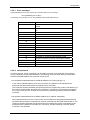
2.5.4.3 Parameter class 53 [DEVICE_CONFIG]
Length of the Class 53 data record in the RAM:
Length of the Class 53 data record during communication:
Class 53
74 bytes (0x004A)
79 bytes
Offset
(hex.)
RAM
COM
Values (ASCII)
String length IEC_ADR
0x00
1
2
‘01‘ .. ‘16‘
Length of IEC address
default: ‘08‘
IEC_ADR
0x01
16
16
Max. 16 characters
(‘0‘ .. ‘9‘, ‘a‘ .. ‘z‘,
‘A‘ .. ‘Z‘)
IEC address of ZDUE
default: ‘99999999‘
String length
length IEC_ IDENT
0x11
1
2
‘01‘ .. ‘16‘
IEC_ IDENT
0x12
16
16
Parameter
Description
Default: ‘15‘
Max. 16 characters Default: ‘1KGL922920R0001‘
[‘ ‘ .. ‘~‘ (20h .. 7Eh)] The last four digits are codes for the
interface variants:
0000: Hardware-Detection-Error
0001: ZDUE-Standard (1MB)
(CL1-, RS232-, RS485-IF)
0002: ZDUE-Standard (2MB)
(2MB Flash/512kB RAM)
(CL1-, RS232-, RS485-IF)
0102: ZDUE-GPRS-Standard
(CL1-, RS232-, RS485-IF)
0012: ZDUE-GPRS-4WRS485
(RS232-, 4-W-RS485-IF)
1002: ZDUE-GPRS-MBus
(CL1-, RS232-, M-Bus-IF)
String length IEC_SET_PW
0x22
1
2
‘00‘ .. ‘16‘
IEC_SET_PW
0x23
16
16
Max. 16 characters
[‘ ‘ .. ‘~‘ (20h .. 7Eh)
without ‘(‘ , ‘)‘]
Default: ‘08‘
IEC_TA
0x33
1
2
‘02‘ .. ‘20‘
Timeout Ta in acc. with EN 62056-21,
Default: ‘15‘ (from V1.210, old ‘09‘)
IEC_TR
0x34
1
2
‘02‘ .. ‘20‘
Timeout Tr in acc. with EN 62056-21,
Default: ‘15‘ (from V1.210, old ‘09‘)
EXT_IF
0x35
1
1
‘0‘
Current Loop (CL1)
‘1‘
RS232
‘2‘
RS485
‘3‘
M-Bus
Default: ‘00000000‘
Meter interface for remote reading
String length EVU_IDENT
0x36
1
2
‘00‘ .. ‘16‘
EVU_IDENT
0x37
16
16
Max. 16 characters
[‘ ‘ .. ‘~‘ (20h .. 7Eh)
without ‘(‘ , ‘)‘]
Reserved for additional
parameters
0x36
20
20
TBD
Default: ‘08‘
Default: ‘00000000‘
Property number of the ZDUE-GSMPLUS-IV in the billing data record
TBD
If, when writing this class, the control centre selects an external COM interface which is not
physically present in the device (e.g. M-Bus) the write command (W1 C5300000000) is
acknowledged with ‘ERROR13‘.
When setting the IEC_ IDENT the firmware of the ZDUE-GSM-PLUS-IV always sets the last four
digits (referring to the string length of the IEC_ IDENT) to the values specified by the hardware
identification.
Page 32 of 92
ZDUE-GSM-PLUS-IV / ZDUE-GPRS-PLUS-IV / ZDUE-LAN-PLUS-IV
Configuration
2.5.4.4 Parameter class 54 [CLOCK_CONFIG]
Length of the Class 54 data record in the RAM:
Length of the Class 54 data record during communication:
Class 54
104 bytes (0x0068)
188 bytes
Offset
(hex.)
RAM
COM
Values (ASCII)
1. Switch time Su <-> Wi
0x00
4
8
‘YYMMDDhh‘
Switch time (Index 0)
2. Switch time Su <-> Wi
0x04
4
8
‘YYMMDDhh‘
Switch time (Index 1)
3. Switch time Su <-> Wi
0x08
4
8
‘YYMMDDhh‘
Switch time (Index 2)
4. Switch time Su <-> Wi
0x0C
4
8
‘YYMMDDhh‘
Switch time (Index 3)
5. Switch time Su <-> Wi
0x10
4
8
‘YYMMDDhh‘
Switch time (Index 4)
6. Switch time Su <-> Wi
0x14
4
8
‘YYMMDDhh‘
Switch time (Index 5)
7. Switch time Su <-> Wi
0x18
4
8
‘YYMMDDhh‘
Switch time (Index 6)
8. Switch time Su <-> Wi
0x1C
4
8
‘YYMMDDhh‘
Switch time (Index 7)
9. Switch time Su <-> Wi
0x20
4
8
‘YYMMDDhh‘
Switch time (Index 8)
10. Switch time Su <-> Wi
0x24
4
8
‘YYMMDDhh‘
Switch time (Index 9)
11. Switch time Su <-> Wi
0x28
4
8
‘YYMMDDhh‘
Switch time (Index 10)
12. Switch time Su <-> Wi
0x2C
4
8
‘YYMMDDhh‘
Switch time (Index 11)
13. Switch time Su <-> Wi
0x30
4
8
‘YYMMDDhh‘
Switch time (Index 12)
14. Switch time Su <-> Wi
0x34
4
8
‘YYMMDDhh‘
Switch time (Index 13)
15. Switch time Su <-> Wi
0x38
4
8
‘YYMMDDhh‘
Switch time (Index 14)
16. Switch time Su <-> Wi
0x3C
4
8
‘YYMMDDhh‘
Switch time (Index 15)
17. Switch time Su <-> Wi
0x40
4
8
‘YYMMDDhh‘
Switch time (Index 16)
18. Switch time Su <-> Wi
0x44
4
8
‘YYMMDDhh‘
Switch time (Index 17)
19. Switch time Su <-> Wi
0x48
4
8
‘YYMMDDhh‘
Switch time (Index 18)
20. Switch time Su <-> Wi
0x4C
4
8
‘YYMMDDhh‘
Time window for call acceptance
0x50
4
8
Hhmmstart
to
hhmmend
Reserved for additional
parameters
0x54
20
20
TBD
Parameter
Description
Switch time (Index 19)
Default configuration: ‘00002400‘
(time window start: 00:00
time window end: 24:00)
TBD
The default configuration for the switching table corresponds to currently valid legal regulations and
is given in code by a default table.
The switch times must be parameterised in chronologically ascending order. The order is not
checked by the firmware!
ZDUE-GSM-PLUS-IV / ZDUE-GPRS-PLUS-IV / ZDUE-LAN-PLUS-IV
Seite 33 von 92
Configuration
2.5.4.5 Parameter class 55 [RS232D]
Length of the Class 55 data record in the RAM:
Length of the Class 55 data record during communication:
Class 55
Parameter
BAUD RATE
DATA FORMAT
17 bytes (0x0011)
19 bytes
Offset
(hex.)
RAM
COM
Values (ASCII)
0x00
1
1
‘0‘
300 baud
‘1‘
600 baud
‘2‘
1200 baud
‘3‘
2400 baud
‘4‘
4800 baud
0x01
1
1
Description
‘5‘
9600 baud
‘6‘
19200 baud
‘7‘
38400 baud
‘8‘
57600 baud
‘9‘
115200 baud
‘0‘
7 data bits, even parity, 1 stop bit
‘1‘
8 data bits, no parity, 1 stop bit
‘2‘
8 data bits, even parity, 1 stop bit
BREAK
0x02
1
1
’0’
Disabled
BREAK_TIME
0x03
2
4
‘0020’ to ‘3000’
20 to 3000 msec, default: 300msec
MODE
0x05
1
1
‘0‘
Mode C monitor (EN 62056-21)
(switch baud rate where appropriate)
‘1‘
Direct transparent operation with fixed
baud rate.
DTR only active when online
‘1’
DTR_MODE
0x06
1
1
‘0‘
Reserved for additional
parameters
0x07
10
10
TBD
‘1‘
Page 34 of 92
Enabled
DTR always active
TBD
ZDUE-GSM-PLUS-IV / ZDUE-GPRS-PLUS-IV / ZDUE-LAN-PLUS-IV
Configuration
2.5.4.6 Parameter class 56 [CL1]
Length of the Class 56 data record in the RAM:
Length of the Class 56 data record during communication:
Class 56
Parameter
BAUD RATE
DATA FORMAT
BREAK
16 bytes (0x0010)
18 bytes
Offset
(hex.)
RAM
COM
Values (ASCII)
0x00
1
1
‘0‘
300 baud
‘1‘
600 baud
‘2‘
1200 baud
‘3‘
2400 baud
‘4‘
4800 baud
0x01
0x02
1
1
1
1
Description
‘5‘
9600 baud
‘6‘
19200 baud
‘0‘
7 data bits, even parity, 1 stop bit
‘1‘
8 data bits, no parity, 1 stop bit
‘2‘
8 data bits, even parity, 1 stop bit
’0’
disabled
‘1’
enabled
BREAK_TIME
0x03
2
4
‘0020’ to ‘3000’
20 to 3000 msec, default: 300msec
MODE
0x05
1
1
‘0‘
Mode C monitor (EN 62056-21)
(switch baud rate where appropriate)
‘1‘
Direct transparent operation with fixed
baud rate.
Reserved for additional
parameters
0x06
10
10
TBD
ZDUE-GSM-PLUS-IV / ZDUE-GPRS-PLUS-IV / ZDUE-LAN-PLUS-IV
TBD
Seite 35 von 92
Configuration
2.5.4.7 Parameter class 57 [RS485_MBUS]
Length of the Class 57 data record in the RAM:
Length of the Class 57 data record during communication:
Class 57
Parameter
BAUD RATE
DATA FORMAT
BREAK
16 bytes (0x0010)
18 bytes
Offset
(hex.)
RAM
COM
Values (ASCII)
0x00
1
1
‘0‘
300 baud
‘1‘
600 baud
‘2‘
1200 baud
‘3‘
2400 baud
‘4‘
4800 baud
0x01
0x02
1
1
1
1
Description
‘5‘
9600 baud
‘6‘
19200 baud
‘7‘
38400 baud
‘8‘
57600 baud
‘0‘
7 data bits, even parity, 1 stop bit
‘1‘
8 data bits, no parity, 1 stop bit
‘2‘
8 data bits, even parity, 1 stop bit
’0’
disabled
‘1’
enabled
BREAK_TIME
0x03
2
4
‘0020’ to ‘3000’
20 to 3000 msec, default: 300msec
MODE
0x05
1
1
‘0‘
Mode C monitor (EN 62056-21)
(switch baud rate where appropriate)
‘1‘
Direct transparent operation with fixed
baud rate.
Reserved for additional
parameters
Page 36 of 92
0x06
10
10
TBD
TBD
ZDUE-GSM-PLUS-IV / ZDUE-GPRS-PLUS-IV / ZDUE-LAN-PLUS-IV
Configuration
2.5.4.8 Parameter class 58 [LPRF]
Length of the Class 58 data record in the RAM:
Length of the Class 58 data record during communication:
Class 58
Parameter
MEASUREMENT PERIOD
Offset
(hex.)
RAM
COM
0x00
1
2
86 bytes (0x0056)
93 bytes
Values (ASCII)
Description
‘05‘
5 minutes
‘15‘
15 minutes
‘30‘
30 minutes
‘60‘
60 minutes
ACTIVE PULSE EDGE LP1
0x01
1
1
‘0‘
Falling edge
‘1‘
Rising edge
ACTIVE PULSE EDGE LP2
0x02
1
1
‘0‘
Falling edge
‘1‘
Rising edge
ACTIVE PULSE EDGE LP3
0x03
1
1
‘0‘
Falling edge
‘1‘
Rising edge
MINIMUM PULSE DURATION
LP1
0x04
1
3
‘010‘ to ‘150‘
Default configuration: 20 msec
MINIMUM PULSE DURATION
LP2
0x05
1
3
‘010‘ to ‘150‘
Default configuration: 20 msec
MINIMUM PULSE DURATION
LP3
0x06
1
3
‘010‘ to ‘150‘
Default configuration: 20 msec
Length of EDIS INDEX NO. LP1
0x07
1
1
‘1‘ .. ‘7‘
EDIS INDEX NO. LP1
0x08
7
7
Max. 7 characters
(20h .. 7Eh)
Length of MEASURING UNIT LP1
0x0F
1
1
‘1‘ .. ‘7‘
MEASURING UNIT LP1
0x10
7
7
Max. 7 characters
(20h .. 7Eh)
Length of EDIS INDEX NO. LP2
0x17
1
1
‘1‘ .. ‘7‘
EDIS INDEX NO. LP2
0x18
7
7
Max. 7 characters
(20h .. 7Eh)
Length of MEASURING UNIT LP2
0x1F
1
1
‘1‘ .. ‘7‘
MEASURING UNIT LP2
0x20
7
7
Max. 7 characters
(20h .. 7Eh)
Length of EDIS INDEX NO. LP3
0x27
1
1
‘1‘ .. ‘7‘
EDIS INDEX NO. LP3
0x28
7
7
Max. 7 characters
(20h .. 7Eh)
Length of MEASURING UNIT LP3
0x2F
1
1
‘1‘ .. ‘7‘
MEASURING UNIT LP3
0x30
7
7
Max. 7 characters
(20h .. 7Eh)
LP3-FUNCTION
0x37
1
1
‘0‘
Pulse input
‘1‘
Sync input for load profile
Length MEDIUM LP1
0x38
1
1
‘0‘ .. ‘4‘
Default configuration: ‘3‘
MEDIUM LP1
0x39
4
4
Max. 4 characters
(0x20h .. 0x7E)
Length MEDIUM LP2
0x3D
1
1
‘0‘ .. ‘4‘
MEDIUM LP2
0x3E
4
4
Max. 4 characters
(0x20h .. 0x7E)
Length MEDIUM LP3
0x42
1
1
‘0‘ .. ‘4‘
MEDIUM LP3
0x43
4
4
Max. 4 characters
(0x20h .. 0x7E)
Reserved for additional
parameters
0x38
30
30
TBD
ZDUE-GSM-PLUS-IV / ZDUE-GPRS-PLUS-IV / ZDUE-LAN-PLUS-IV
Default configuration: ‘3‘
Default configuration: ‘1.5‘
Default configuration: ‘2‘
Default configuration: ‘kW‘
Default configuration: ‘3‘
Default configuration: ‘1.5‘
Default configuration: ‘2‘
Default configuration: ‘kW‘
Default configuration: ‘3‘
Default configuration: ‘1.5‘
Default configuration: ‘2‘
Default configuration: ‘kW‘
Default configuration: ‘1.5‘
Default configuration: ‘2‘
Default configuration: ‘kW‘
Default configuration: ‘3‘
Default configuration: ‘1.5‘
TBD
Seite 37 von 92
Configuration
2.5.5 Billing data of the ZDUE devices
2.5.5.1 General
If the control centre responds to the ZDUE’s identification telegram with the following answer telegram
‘<ACK>0Z0<CR><LF>‘, the ZDUE sends its billing data record. This billing data record is structured
in accordance with the subsequent table:
EDIS index no.
Field length
1-1:F.F
1-1:0.0.0
1-1:0.2.0
1-1:0.9.1
1-1:0.9.2
2)
Parameterisation
8
16 (Def. 8)
8
6
6
10
Format
hexadecimal
Character string
Character string
hhmmss
jjmmtt
Number
2)
Parameterisation 10
Number
2)
Parameterisation 10
Number
1-1:C.90.1
15
Number
1-1:C.90.2
15
Number
1-1:C.91.0
15
Character string
1-1:C.92.0
3
Number
Connection data (ZDUE-GPRS-PLUS-IV only)
1-1:C.93.1
20
Number
1-1:C.93.2
20
Number
1-1:C.94.1
20
Number
1-1:C.94.2
20
Number
1-1:C.95.1
20
Number
1-1:C.95.2
20
Number
Function
Error status
Property no. of the ZDUE 1)
Program version
Time
Date
Meter reading 1 (current measurement
period)
Meter reading 2 (current measurement
period)
Meter reading 3 (current measurement
period)
MAC address of the ZDUE-LAN-PLUS IV or
IMEI of the ZDUE-GSM-PLUS-IV/ZDUEGPRS-PLUS-IV
IMSI with ZDUE-GSM-PLUS-IV/ZDUEGPRS-PLUS-IV; otherwise empty
Version of GSM module when ZDUE-GSMPLUS-IV/ZDUE-GPRS-PLUS-IV; otherwise
empty
GSM signal strength when ZDUE-GSMPLUS-IV/ZDUE-GPRS-PLUS-IV; otherwise
empty
Tx-Bytes, current month when using ZDUEGPRS-PLUS-IV; otherwise empty
Rx-Bytes, current month when using ZDUEGPRS-PLUS-IV; otherwise empty
Tx-Bytes, previous month when using
ZDUE-GPRS-PLUS-IV; otherwise empty
Rx-Bytes, previous month when using
ZDUE-GPRS-PLUS-IV; otherwise empty
Tx-Bytes, total when using ZDUE-GPRSPLUS-IV; otherwise empty
Rx-Bytes, total when using ZDUE-GPRSPLUS-IV; otherwise empty
1)
The property number provided in the billing data record is being gathered from the parameter entry
EVU_IDENT in class 53.
2)
The EDIS index nos. for the meter readings are being gathered from the parameterisation (class 58),
LP1-LP3). They are structured as follows: ‘<Medium LPx><EDIS index no. LPx>‘
Example (Default parameterisation):
‘1-1.5‘
Page 38 of 92
ZDUE-GSM-PLUS-IV / ZDUE-GPRS-PLUS-IV / ZDUE-LAN-PLUS-IV
Configuration
2.5.5.2 Format of the error status
The error status is a hexadecimal-coded 32-bit number, which consists of the following status bits
(displayed in brackets is the Bit no. in the operating status word of the ZDUE, see section Status
commands):
Bit 0
(Bit 08): Return of power
Bit 1
(Bit 09): Load profile memory deleted
Bit 2
(Bit 10): Parameter reloaded
Bit 8
(Bit 04): Parameter checksum incorrect
Bit 16 (Bit 05): Parameter write / read error
Bit 17 (Bit 06): AVR read/write error
Bit 18 (Bit 07): Data Flash write / read error
Bit 24 (Bit 00): Time difference while setting up the clock larger than 1 minute
Bit 25 (Bit 01): Clock is reset to default due to depleted power reserve
Bit 26 (Bit 02): Switching between winter and summer time
Example: Billing data of the ZDUE-LAN-PLUS IV
1-1:F.F(00000001)
1-1:0.0.0(12345678)
1-1:0.2.0( 1.000)
1-1:0.9.1(182305)
1-1:0.9.2(050823)
1-1.5(0000000000)
1-1.5(0000000000)
1-1.5(0000000000)
1-1:C.90.1( 00604CC7100B)
1-1:C.90.2( )
1-1:C.91.0( )
1-1:C.92.0( )
1-1:C.93.1( )
1-1:C.93.2( )
1-1:C.94.1( )
1-1:C.94.2( )
1-1:C.95.1( )
1-1:C.95.2( )
Error status
Property no. of ZDUE
Firmware version ZDUE-LAN-PLUS IV
Time (hhmmss)
Date (yymmdd)
Current meter reading LP1
Current meter reading LP2
Current meter reading LP3
MAC address (right-aligned, 12 digits, without ‘ : ‘)
[ IMSI ]
[ Firmware version GSM module ]
[ Field strength ]
ZDUE-GSM-PLUS-IV / ZDUE-GPRS-PLUS-IV / ZDUE-LAN-PLUS-IV
Seite 39 von 92
Configuration
2.5.6 Communication commands in acc. with DIN EN 62056-21
The following sections document the commands supported by the ZDUE-GSM-PLUS-IV. The data
record elements they contain are described in the following.
The command descriptions use symbolic data record elements (e.g. for timestamps). Their structure is
the same for all command categories.
1.
Timestamp ZSTs13:
2.
Timestamp ZSTs11:
3.
Timestamp ZS7:
4.
Timestamp DS7:
5.
Set password:
6.
7.
n:
KZ:
8.
S:
yYYMMDDhhmmss
y
= time zone
(0=winter time, 1 =summer time)
YY
= year
(00..99)
MM
= month
(01..12)
DD
= day
(01..31)
hh
= hour
(00..23)
mm
= minute
(00..59)
ss
= second
(00..59)
yYYMMDDhhmm
y
= time zone
(0=winter time, 1=summer time)
YY
= year
(00..99)
MM
= month
(01..12)
DD
= day
(01..31)
hh
= hour
(00..23)
mm
= minute
(00..59
yhhmmss
y
= time zone
(0=winter time, 1=summer time)
hh
= hour
(00..23)
mm
= minute
(00..59)
ss
= second
(00..59)
yYYMMDD
y
= time zone
(0=winter time, 1=summer time)
YY
= year
(00..99)
MM
= month
(01..12)
DD
= day
(01..31)
String with max. 16 characters excluding the characters '(', ')', '/', '!' or
empty string
Blockette length in R6 commands (1 .. 99)
EDIS index no.:
‘P.01‘ for load profile
‘0.9.1‘ for time
‘0.9.2‘ for date
Profile status word (bit-coded, bit 7 ..... bit 0)
Bit
B7
B6
B5
B4
B3
B2
B1
B0
9. RP:
10. z:
11. KZn :
12. En :
13. Mwn :
Page 40 of 92
Meaning
Power failure
Return of power
Time reset
Measurement period changed
Time switch (winter time <-> summer time)
Incomplete measurement period
reserved
Fatal error
Registration period
No. of different measured values in a registration period
Index nos. of measured values (not giving rate / previous value index
no.)
Unit of measured values
Measured values
ZDUE-GSM-PLUS-IV / ZDUE-GPRS-PLUS-IV / ZDUE-LAN-PLUS-IV
Configuration
2.5.6.1 Error messages
The ZDUE-GSM-PLUS-IV may respond to a command with an error message:
<STX>(ERRORnn)<ETX><BCC>
The following error numbers ‘nn‘ can be generated by the ZDUE-GSM-PLUS-IV:
Error numbers (nn)
00
02
03
04
05
06
07
08
09
10
11
12
13
14
Error
Command invalid (construction / contents of data
record)
Command unknown (command ID, command type
ID)
Class invalid
Time/date invalid (inadmissible values)
Parameter for ‘External COM interface‘ invalid
Maximum numbers of service commands exceeded
99
Malfunction when executing a debug command
01
2.5.6.2 Set password
In order to execute various commands it is necessary to transfer a set password (as a 2nd data
record). Depending on the parameterisation, the following cases can arise during communication
between the ZDUE-GSM-PLUS-IV and the control centre:
No set password parameterised in the ZDUE-GSM-PLUS-IV (string length = 0):
In this case the ZDUE-GSM-PLUS-IV will not perform an evaluation of the transferred set
passwords (all password-protected commands can be executed).
The request to send the password (P0-Operand) when the programming mode is activated may in
this case be answered with the password command (P1 command, any password). Alternatively,
the control centre can also continue communication by transferring another permissible VDEW
command.
Set password parameterised in the ZDUE-GSM-PLUS-IV (default: ‘00000000‘)
All the passwords sent from the control centre must correspond to the parameterised password,
otherwise communication is interrupted by a break command from the ZDUE-GSM-PLUS-IV. The
request to send the password (P0-Operand) when the programming mode is activated must be
answered with the password command (P1 command). The direct sending of another VDEW
command is not permitted.
ZDUE-GSM-PLUS-IV / ZDUE-GPRS-PLUS-IV / ZDUE-LAN-PLUS-IV
Seite 41 von 92
Configuration
2.5.6.3 Load profile commands
R5 commands:
1.
Read load profile (time domain)
Command format:
<SOH>R5<STX>P.01(ZSTs11;ZSTs11)<ETX><BCC>
2.
Read load profile (from a start time to the end of recording)
Command format:
<SOH>R5<STX>P.01(ZSTs11;)<ETX><BCC>
3.
Read load profile (from the beginning of recording to an end time)
Command format:
<SOH>R5<STX>P.01(;ZSTs11)<ETX><BCC>
4.
Read load profile (complete load profile)
Command format:
<SOH>R5<STX>P.01(;)<ETX><BCC>
The season ID ‘y‘ is ignored when requesting data.
R6 commands:
1.
Read load profile in blockettes (time domain)
Command format:
<SOH>R6<STX>P.01(ZSTs11;ZSTs11;n)<ETX><BCC>
Answer format:
<STX>KZ(ZSTs13)(S)(RP)(z)(KZ1)(E1)...(KZz)(Ez)(Mw1)....(Mwz)
Example: Readout of load profile from 26.08.2000 13:30.00 to end of recording (here
27.08.2000 00:30.00) in blockettes @ 4 lines:
HHU
MTM
HHU
MTM
HHU
MTM
HHU
Page 42 of 92
<SOH>R6<STX>P.01(10008261330;;4)<ETX><BCC>
<STX>P.01(1000826133000)(00)(15)(3)(1.5)(kW)(1.5)(kW)(1.5)(kW)<CR><LF>
(000000)(000124)(001521)<CR><LF>
(000000)(000098)(000952)<CR><LF>
(000000)(000128)(001232)<CR><LF>
<EOT><BCC>
<ACK>
(000000)(000324)(001961)<CR><LF>
(000000)(000498)(003052)<CR><LF>
(000000)(000428)(002132)<CR><LF>
(000000)(000299)(002143)<CR><LF>
<EOT><BCC>
<ACK>
:
:
:
<STX>P.01(1000827001500)(00)(15)(3)(1.5)(kW)(1.5)(kW)(1.5)(kW)<CR><LF>
(000000)(000124)(001521)<CR><LF>
(000000)(000098)(000952)<CR><LF>
<ETX><BCC>
<ACK>
ZDUE-GSM-PLUS-IV / ZDUE-GPRS-PLUS-IV / ZDUE-LAN-PLUS-IV
Configuration
2.
Read load profile (from a start time to the end of recording)
Command format:
<SOH>R6<STX>P.01(ZSTs11;;n)<ETX><BCC>
3.
Read load profile (from the beginning of recording to an end time)
Command format:
<SOH>R6<STX>P.01(;ZSTs11;n)<ETX><BCC>
4.
Read load profile (complete load profile)
Command format:
<SOH>R6<STX>P.01(;;n)<ETX><BCC>
n: no. of elements per blockette
W5 commands:
1.
Delete load profile (completely)
Command format:
<SOH>W5<STX>P.01(;)(set password)<ETX><BCC>
2.5.6.4 Parameter commands
Setting and reading parameters is done via W1 / R3 commands (ASCII-code characters).
With Class the individual parameter segments are selected, with the command parameters ‘Offset‘
and ‘Length‘ individual parameters or parameter areas in a class can be accessed. This, however, is
not supported by the ZDUE-GSM-PLUS-IV; the classes can only be written or read completely (Class
‘Offset‘ and ‘Length‘ equals ‘0000‘).
W1 commands:
Write class (completely)
Command format:
<SOH>W1<STX>C<class>00000000(<data>)(set password)<ETX><BCC>
Example: Setting the parameters of the subgroup [DEVICE_CONFIG] (Class 53) to the following values:
Device address:
Communication ID:
Set password:
IEC timeout Ta:
IEC timeout Tr:
External interface:
‘12345678‘
‘1KGL922920R0102‘
‘87654321‘
‘09‘
‘09‘
‘1‘
(device with CL1 and RS-232)
(RS-232 interface)
HHU
/?99999999!<CR><LF>
MTM
/ABB61KGL922470R0002<CR><LF>
HHU
<ACK>061<CR><LF>
MTM
<SOH>P0<STX>(00000001)<ETX><BCC>
HHU
<SOH>P1<STX>(00000000)<ETX><BCC>
MTM
<ACK>
HHU
<SOH>W1<STX>C5300000000(081234567800000000151KGL922920R01020
0887654321000000000909108000000000000000000)(00000000)<ETX><BCC>
MTM
<ACK>
HHU
<SOH>B0<ETX><BCC>
ZDUE-GSM-PLUS-IV / ZDUE-GPRS-PLUS-IV / ZDUE-LAN-PLUS-IV
Seite 43 von 92
Configuration
R3 commands:
1.
Read class in blockettes
Command format:
<SOH>R3<STX>C<class<00000000( )<ETX><BCC>
Answer format:
<STX>0000(<data record>)[<EOT> | <ETX>]<BCC>
0000
<data record>
Example:
HHU
MTM
HHU
MTM
HHU
MTM
HHU
MTM
HHU
Example:
HHU
MTM
HHU
MTM
HHU
MTM
HHU
MTM
HHU
MTM
HHU
MTM
HHU
MTM
HHU
= offset (ASCII characters hexadecimal-coded)
= class data (max. 64 ASCII characters per blockette)
Reading Class 55 with offset ‘0000‘, length ‘0000‘ (reading of RS232-/RS485
parameters):
/?99999999!<CR><LF>
/ABB61KGL922920R0002<CR><LF>
<ACK>061<CR><LF>
<SOH>P0<STX>(00000001)<ETX><BCC>
<SOH>P1<STX>(00000000)<ETX><BCC>
<ACK>
<SOH>R3<STX>C5500000000( )<ETX><BCC>
<STX>0000(6010300000000000000)<ETX><BCC>
<ACK>
Reading Class 54 with offset ‘0000‘, length ‘0000‘ (reading clock parameters ->
several blockettes required, repetition of the last blockette due to transfer error):
/?99999999!<CR><LF>
/ABB61KGL922920R0002<CR><LF>
<ACK>061<CR><LF>
<SOH>P0<STX>(00000001)<ETX><BCC>
<SOH>P1<STX>(00000000)<ETX><BCC>
<ACK>
<SOH>R3<STX>C5400000000( )<ETX><BCC>
<STX>0000(0110280302033102021028030303300203102603040328020410310305032702)<EOT><BCC>
<ACK>
<STX>0040(0510300306032602061029030703250207102803080330020810260309032902)<EOT><BCC>
<ACK>
<STX>0080(091025031003280210103103110327020000240000000000000000000000)<ETX><BCC>
<NAK>
<STX>0080(091025031003280210103103110327020000240000000000000000000000)<ETX><BCC>
<ACK>
2.5.6.5 Parameter transfer command
In order for newly written parameters to be adopted at a particular time the following command is
defined.
With the execution of this command the data of the previously transferred "Write class" commands are
transferred to the non-volatile memory.
Until this command is executed the old parameters remain active.
A readout of the data prior to acceptance by means of the command outputs the old values.
Sending a Break deletes the temporary data set in the device by "Write class" commands. In this way,
incorrect "Write class" commands can be undone as long as the W1 command defined here has not
been given. The temporary data are also deleted by a disconnect or an inactivity timeout (60 s).
Command format:
Page 44 of 92
<SOH>W1<STX>P01()(set password)<ETX><BCC>
ZDUE-GSM-PLUS-IV / ZDUE-GPRS-PLUS-IV / ZDUE-LAN-PLUS-IV
Configuration
2.5.6.6 Time / date commands
Set time:
Command format:
<SOH>W5<STX>0.9.1(ZS7)(set password)<ETX><BCC>
Set data:
Command format:
<SOH>W5<STX>0.9.2(DS7) (set password) <ETX><BCC>
Read time:
Command format:
Response format:
<SOH>R5<STX>0.9.1()<ETX><BCC>
<STX>0.9.1(ZS7)<ETX><BCC>
Read date:
Command format:
Response format:
<SOH>R5<STX>0.9.2()<ETX><BCC>
<STX>0.9.2(DS7)<ETX><BCC>
2.5.6.7 Status commands
Events and error messages are recorded in the ZDUE-GSM-PLUS-IV in an operating status word.
This is stored in the volatile SRAM, i.e. it is lost in the event of a power failure.
The status word can be read out of the device in order to determine the current operating status.
Bit in status
word
Bit 0
Bit 1
Bit 2
Bit 3
Bit 4
Bit 5
Bit 6
Bit 7
Bit 8
Bit 9
Bit 10
Bit 11
Bit 12
Bit 13
Bit 14
Bit 15
Displayed error condition / event
Deviation > +/- 1 minute when setting clock
Device clock initialised to 01.01.2000 00:00.00 due to
exhausted power reserve
Time switch-over (summer time <-> standard time)
Reserved
Parameter checksum incorrect (Data Flash)
Parameter write / read error
Reserved (e.g. AVR write / read error)
Data Flash error
Return of power
Load profile memory deleted
Parameter reload from non-volatile memory
Error status
(LED red)
No
No
No
Yes
Yes
Yes
Yes
No
No
No
Reserved
Reserved
Reserved
Reserved
Reserved
Other status information that can be read out of the ZDUE are:
- GSM field strength
- GSM network operator (z. B. MOVISTAR)
- GSM location area ID
- GSM cell ID
- IMEI (International Mobile station Equipment Identity): serial number of the GSM module
- IMSI (International Mobile Subscriber Identity): ID number of the SIM card
ZDUE-GSM-PLUS-IV / ZDUE-GPRS-PLUS-IV / ZDUE-LAN-PLUS-IV
Seite 45 von 92
Configuration
The ZDUE-GSM-PLUS-IV allows the readout and resetting of the status word. During reading the
highest-value bit is transferred first, with each bit represented by an ASCII character ‘0‘ or ‘1‘.
Read status word:
Command format:
<SOH>R3<STX>S70()<ETX><BCC>
Response:
<STX>S70(b16b15b14 ...... b00)<ETX><BCC>
bnn :
‘0‘ = no event/status occurred / inactive
‘1‘ = event/status occurred / active
Example: In the status word, bit 0 (deviation >+/- 1 minute when setting the clock) and
bit 8 (return of power) are set.
HHU
MTM
HHU
MTM
HHU
MTM
HHU
MTM
MTM
HHU
/?99999999!<CR><LF>
/ABB61KGL922920R0002<CR><LF>
<ACK>061<CR><LF>
<SOH>P0<STX>(00000001)<ETX><BCC>
<SOH>P1<STX>(00000000)<ETX><BCC>
<ACK>
<SOH>R3<STX>S70()<ETX><BCC>
<STX>S70(0000000100000001)<ETX><BCC>
<ACK>
<SOH>B0<ETX><BCC>
Reset status word:
Command format:
<SOH>W1<STX>S70()<ETX><BCC>
2.5.6.8 Service commands
W1 commands:
1.
Parameter reset to default configuration:
This command loads the default parameters. All customer-specific settings are overwritten.
Command format:
<SOH>W1<STX>S98( )<ETX><BCC>
The overwritten parameters are stored in the non-volatile memory. The LED is set
to 'red flashing'.
This command is also permissible via the network (GSM interface, LAN
Page 46 of 92
interface).
This command is executed immediately (without an additional break being
transmitted) upon completion of the command.
The manufacturer's passwords and the manufacturer's device address are not
reset by this command.
ZDUE-GSM-PLUS-IV / ZDUE-GPRS-PLUS-IV / ZDUE-LAN-PLUS-IV
Configuration
R3 commands:
1. Readout parameter checksum:
Command format:
<SOH>R3<STX>S61( )<ETX><BCC>
Response:
cccc :
<STX>S61(cccc)<ETX><BCC>
Hex-coded 16-bit parameter checksum
2. Readout current status of load profile pulse inputs:
Command format:
Response:
<SOH>R3<STX>S62( )<ETX><BCC>
<STX>S62(S1S2S3)<ETX><BCC>
S1 = status of pulse input 1:
S2 = status of pulse input 2:
S3 = status of pulse input 3:
‘0’ = open, ‘1’ = closed
‘0’ = open, ‘1’ = closed
‘0’ = open, ‘1’ = closed
3. Readout firmware version of ZDUE:
Command format:
<SOH>R3<STX>S63( )<ETX><BCC>
Response:
<STX>S63(DNT8109_V1.320)<ETX><BCC>
4. Read firmware version of GSM module:
Command format:
<SOH>R3<STX>S64( )<ETX><BCC>
Response (examples): <STX>S64(03.10)<ETX><BCC>
<STX>S64(Sagem KY3,XG)<ETX><BCC>
or
5. Read GSM operating/module parameters:
Command format:
<SOH>R3<STX>S65( )<ETX><BCC>
With this command the following GSM operating/module parameters can be requested:
GSM field strength (3-digit, decimally coded, e.g. ‘078’ => -78dBm, ‘na’ => not
available)
Mobile handler supplies field strength as ‘Char’ (module format) -> conversion
necessary.
GSM network operator (max. 20 characters, alphanumerical format, e.g. ‘D1Telekom’),
GSM location area ID (max. 8-digit, hex-coded),
GSM cell ID (max. 8-digit, hex-coded),
IMEI (International Mobile station Equipment Identity):
serial number of GSM module (max. 25 characters),
IMSI (International Mobile Subscriber Identity):
ID number of SIM card (max. 25 characters).
Response: <STX>S65(078)(D1Telekom)(43AC)(8AD1)(500031283001278)(73427464820212334)<ETX><BCC>
This command is also permissible via the GSM interface.
ZDUE-GSM-PLUS-IV / ZDUE-GPRS-PLUS-IV / ZDUE-LAN-PLUS-IV
Seite 47 von 92
Configuration
6.
Readout most recent measurement period values:
Command format:
Response:
Page 48 of 92
<SOH>R3<STX>S90( )<ETX><BCC>
<STX>S90(000000090000001200000023)<ETX><BCC>
-------------MP value LP1 (decimal)
------------MP value LP2 (decimal)
------------- MP value LP3 (decimal)
ZDUE-GSM-PLUS-IV / ZDUE-GPRS-PLUS-IV / ZDUE-LAN-PLUS-IV
The GSM log
2.6
The GSM log
Purpose and
benefits
Information
elements of each
entry
In the GSM log the ZDUE-GSM-PLUS-IV records key events and status
changes that occur in
GSM communication
GSM operating parameters
local meter communication
special events.
The readout of the GSM log takes place in acc. with DIN EN 61107 and the
definitions of the VDEW specifications.
The GSM log can be used to ascertain error sources.
The memory for the load profile is implemented as a circulating memory, i.e.
when the end of the memory is reached a new entry overwrites the oldest
load profile entry. Up to 1,372 entries can be stored. This is equivalent to
about 14 days given a recording period of 15 minutes.
Each entry in the GSM log contains the following information elements:
Date / time
Cause of the entry
Registration status (GSM)
Network operator (alphanumerical, GSM)
Location area ID (GSM)
Cell ID (GSM)
Field strength (GSM)
2.6.1 Causes for an entry in the GSM log
The following events or condition changes result in a log entry (fields on a grey background apply to
the ZDUE-GPRS-PLUS-IV only):
Cause
Description
GSM operating parameters
001
002
003
004
005
GSM/GPRS communication
101
102
103
Change / init of the registration status.
Change of Cell ID and / or Location Area.
Change of operator / addition of operator after every module reset / PowerUp.
PIN change (successful): the command to change the PIN (AT+CPWD=) was acknowledged
with OK.
PIN error: the PIN parameterised in ‘para.ini‘ does not match the one on the SIM card. This
entry is generated following the 2nd PIN transfer with ERROR acknowledgement.
Incoming call
CSD connect
Outgoing call
104
105
106
107
108
109
110
GPRS-CONNECT (ATD*99***1#)
Mobile handler received ‘NO CARRIER‘ from the mobile or carrier signal loss
Socket-CONNECT
Socket-DISCONNECT
TSC-CONNECT
TSC-DISCONNECT
Watchdog-packet sent to TSC (currently marked as commentary only)
111
112
113
114
PPP-CONNECT
PPP-DISCONNECT
RING from TSC (from V2.031)
CONNECT between control centre and DM600-GPRS via TSC (from V2.031)
ZDUE-GSM-PLUS-IV / ZDUE-GPRS-PLUS-IV / ZDUE-LAN-PLUS-IV
Seite 49 von 92
The GSM log
115
Local communication
201
202
203
204
205
206
207
208
DISCONNECT between control centre and DM600-GPRS via TSC (from V2.031)
Meter communication:
billing data readout successful.
Meter communication:
data readout in programming mode without using P1 command.
Meter communication:
data readout in manufacturer mode without using P1 command.
Meter communication:
communication closed after acknowledgement telegram (data readout).
Meter communication:
communication closed after acknowledgement telegram (programming mode).
Meter communication:
communication closed after acknowledgement telegram (manufacturer-specific)
Meter communication:
communication closed after identification telegram of meter
Meter communication:
communication closed after request telegram from control centre
Parameterisation /
firmware updates
301
302
303
Time / date
401
402
403
Device parameterised (ZDUE: execution of parameter transfer command).
Firmware update carried out successfully.
Operating status word of ZDUE reset by control centre.
Automatic entry due to timeout (by default every 10 minutes if no other event occurs).
Time reset in device (RTC).
Date reset in device (RTC).
Although events 201 to 208 are registered in the online phase the log entry does not take place until
the connection is established. If there are several communication cycles during the online
(transparent) phase the CAUSE therefore describes only the sequence of the last cycle.
2.6.2 EDIS index no. of the GSM log
Default setting: P.98 The GSM log is treated like a profile. The default setting for the index number
for the GSM log is “98". This index number can be parameterised between
50 and 98. In the following sections the default value 98 is always used.
In accordance with draft DIN 43863-3 : 1998-12 (EDIS), section 6.2 the index
numbers 50 to 89 are manufacturer-specific.
2.6.3 Readout of the GSM log with R5 commands
The readout of the GSM log is done via the formatted commands "R5" or
"R6". As supplements to DIN EN 62056-21 these are determined as follows:
Page 50 of 92
R5
triggers the output of a log formatted with EDIS in programming mode.
The answer generated by the ZDUE is given as a closed telegram.
R6
corresponds to the command "R5", with the answer split into
blockettes to enable blockette-wise readouts.
ZDUE-GSM-PLUS-IV / ZDUE-GPRS-PLUS-IV / ZDUE-LAN-PLUS-IV
The GSM log
Command "R5", GSM log:
Analogous to the load profile readout, the GSM log is transferred:
Task
Readout
GSM log
EDIS index
number;
template:
GG.AA
Required parameters
(the brackets are the separators
in acc. with DIN EN 62056-21)
Index no.:
Readout of the full operating log
available in the ZDUE-GSM-PLUS-IV:
GG P
AA 98.
(;)
Remarks
1) The semicolon must also be
transferred as a special separator.
2) The timestamp before the semicolon
marks the beginning of the interval to
be read out.
Readout of an interval:
( ZSTs11 ; ZSTs11 )
3) The timestamp after the semicolon
Readout from the beginning of the log
recording to an end time:
( ; ZSTs11 )
marks the end of the interval to be
read out.
4) Both timestamps are within the
Readout from a start time to the end of
the recording in the ZDUE-GSMPLUS-IV:
interval limits.
5) If a timestamp is omitted (the
( ZST11 ; )
separators brackets and semicolon
follow in direct succession or vice
versa) the beginning or the end of
the log recording in the device is
used as the interval limit.
Table: Log readout with R5
The telegram supplied as the answer corresponds to the form, given in EDIS, of a log profile.
If the task requests a time zone for which there are no entries the ZDUE replies with "P.98 (ERROR)".
Examples of the command "R5", GSM log:
Task sent to the ZDUE-GSM-PLUS-IV:
SOH R 5 STX
P.98
(
"Supply all entries in the recorded GSM log"
;
)
ETX
BCC
Response from the ZDUE-GSM-PLUS-IV (output of profile):
STX
Log profile
ETX
BCC
Response from the ZDUE-GSM-PLUS-IV (values not available):
STX
P.98
( ERROR )
Task sent to the ZDUE-GSM-PLUS-IV:
SOH R 5 STX
P.98
(
ETX
BCC
"Supply an extract of the GSM log"
ZSTs11
;
ZSTs11
)
ETX
BCC
Response from the ZDUE-GSM-PLUS-IV:
STX
Extract of the log profile
ETX
BCC
ZDUE-GSM-PLUS-IV / ZDUE-GPRS-PLUS-IV / ZDUE-LAN-PLUS-IV
Seite 51 von 92
The GSM log
The section described as "log profile" is composed from a chain of log entries. As with profiles in
general, the number of these entries cannot be recognised at the beginning of the telegram. Each log
entry is structured as followed:
KZ (ZSTs13) (BS) ( )
(6)
(KZ1)(E1) ... (KZ6)(E6)
Log entry header
(Element
1)
...
(Element
6)
Log entry content
KZ
EDIS index no. ‘P.98’,
ZSTs13
timestamp of log entry,
BS
operating status word of the ZDUE-GSM-PLUS-IV
()
corresponds to "RP" in load profiles; not required here,
6
no. of elements in a log entry, fixed at ‘6‘
KZ1
index no. of the element ‘(cause)’ of the log entry:
E1
unit of the element ‘(cause)’ of the log entry:
()
KZ2
index no. of the element ‘(field strength)’ of the log entry:
()
E2
unit of the element ‘(field strength)’ of the log entry:
(dBm)
KZ3
index no. of the element ‘(registration status)’ of the log entry:
()
E3
unit of the element ‘(registration status)’ of the log entry:
()
KZ4
index no. of the element ‘(location area ID)’ of the log entry:
()
E4
unit of the element ‘(location area ID)’ of the log entry:
()
KZ5
index no. of the element ‘(cell ID)’ of the log entry:
()
E5
unit of the element ‘(cell ID)’ of the log entry:
()
KZ6
index no. of the element ‘(network operator)’ of the log entry:
()
E6
unit of the element ‘(network operator)’ of the log entry:
()
Element 1
cause
[ e.g.: (001) ]
Element 2
field strength
[ e.g.: (068) ]
Element 3
registration status
[ e.g.: (1) ]
Element 4
location area ID
[ e.g.: (A0C8) ]
Element 5
cell ID
[ e.g.: (20BE) ]
Element 6
network operator
[ e.g.: (T-D1) ]
()
The total length of the response telegram depends on the magnitude of the desired interval.
Page 52 of 92
ZDUE-GSM-PLUS-IV / ZDUE-GPRS-PLUS-IV / ZDUE-LAN-PLUS-IV
The GSM log
Example: GSM log output:
<STX>P.98(1030604132509)(0100)( )(6)( ) ( )( ) (dBm)( )( )( )( )( )( )( )( )(001)(-068)(1)(A0C8)(20BE)(T-D1)<cr><lf>
P.98(1030604133006)( 0100)( )(6)( )( )( )(dBm)( )( )( )( )( )( )( )( )(003)(-067)(1)(A0C8)(20BE)(T-D1) <cr><lf>
P.98(1030604133528)( 0100)( )(6)( )( )( )(dBm)( )( )( )( )( )( )( )( )(002)(-063)(1)(A0C8)(22D1)(T-D1) <cr><lf>
P.98(1030604134528)( 0100)( )(6)( )( )( )(dBm)( )( )( )( )( )( )( )( )(401)(-065)(1)(A0C8)(22D1)(T-D1) <cr><lf>
P.98(1030604135528)( 0100)( )(6)( )( )( )(dBm)( )( )( )( )( )( )( )( )(401)(-065)(1)(A0C8)(22D1)(T-D1) <cr><lf>
P.98(1030604140343)( 0100)( )(6)( )( )( )(dBm)( )( )( )( )( )( )( )( )(101)(-063)(1)(A0C8)(22D1)(T-D1) <cr><lf>
P.98(1030604140354)( 0100)( )(6)( )( )( )(dBm)( )( )( )( )( )( )( )( )(102)(-067)(1)(A0C8)(22D1)(T-D1) <cr><lf>
P.98(1030604140622)( 0100)( )(6)( )( )( )(dBm)( )( )( )( )( )( )( )( )(204)(-067)(1)(A0C8)(22D1)(T-D1) <cr><lf>
P.98(1030604141622)( 0100)( )(6)( )( )( )(dBm)( )( )( )( )( )( )( )( )(401)(-067)(1)(A0C8)(22D1)(T-D1) <cr><lf>
<ETX><BCC>
2.6.4 Readout of the GSM log in blockettes with R6 commands
Command "R6", readout of profiles using blockettes:
The following tasks can be sent to the ZDUE-GSM-PLUS-IV:
Task
EDIS index
number;
template:
GG.AA
Blockette
readout of GSM
log
See
Table: Log
readout with R5,
page 51
Required parameters
(the brackets are the separators in
acc. with
DIN EN 62056-21)
Remarks
The structure and significance of the
timestamps correspond to the agreements
given with "Readout GSM log".
1) Both semicolons must
also be transferred as
special separators.
In addition, a third parameter is added to the
timestamps via a further semicolon.
2) The text under
'Readout of operating
log' applies to the
timestamps.
Here the parameter entries marked 'Option' in
the table on page 51 are to be transferred
analogously.
Example:
"Readout of an interval"
( ZSTs11 ; ZSTs11 ; n )
3) The third parameter 'n'
indicates the number of
elements per blockette.
Element means exactly
one GSM log entry.
The answers to both tasks correspond to the answers to the tasks described under "R5". The answer
telegrams agreed there of indeterminate length are transferred here in blockettes each containing 'n'
elements. The principle corresponds to DIN EN 62056-21, chapter. 5.4.6, "Communication using
blockettes".
ZDUE-GSM-PLUS-IV / ZDUE-GPRS-PLUS-IV / ZDUE-LAN-PLUS-IV
Seite 53 von 92
The GSM log
2.6.5 Deleting the GSM log with the W5 command
Command "W5":
The tasks listed below can be sent to the ZDUE:
Task
EDIS index
number;
template:
GG.AA
Delete all GSM
log entries
Required parameters
(the brackets are the
separators in acc. with
DIN EN 62056-21)
Index no.:
Remarks
See ‘Readout log' (page 50)
with additionally appended
password;
GG P,
AA 98.
See ‘Readout log’
(page 50)
only the complete deletion of
the GSM log is permissible.
"( ; )"
The password is appended in acc. with the following telegram structure:
SOH
W
5
STX
P.98
(
;
)
(
Password
)
ETX
BCC
The password is also required as a character chain in accordance with password agreement of DIN
EN 62056-21. Following execution of the command, regardless of whether it is successful or not, the
lock opened with the password is reactivated.
An 'ACL', a 'NAK' in acc. with DIN EN 62056-21 Mode C or a telegram containing a character chain is
given as an answer. ‘ACK’ documents the positive confirmation of the delete action and 'NAK' signifies
a transmission error. The character chain containing the text "ERROR" is always sent as an answer if
no section could be deleted (e.g. because the GSM logbook in the required section is empty or the
interval limits given are not permissible).
Example of command "W5":
Task sent to the ZDUE: "Delete the GSM log"
SOH
W
5
STX
P.98
(
;
)
(
Password ) ETX
BCC
Response from the ZDUE if the command could not be executed (example):
STX
P.98
Page 54 of 92
( ERROR )
ETX
BCC
ZDUE-GSM-PLUS-IV / ZDUE-GPRS-PLUS-IV / ZDUE-LAN-PLUS-IV
Updating the firmware
2.7
Updating the firmware
Firmware update by The latest firmware can be transferred to the ZDUE-GSM-PLUS-IV
from the control centre via the GSM network or
control centre
from a computer that is connected direct to the RS-232 interface of the
(remote) or local
ZDUE-GSM-PLUS-IV.
The same conditions apply as for configuration: See
Remote configuration via the GSM network, page 25 and
Local configuration, page 25.
Procedure
Command to upload the firmware:
<SOH>W1<STX>S97()(set password)>ETX><BCC>
The ZDUE-GSM-PLUS-IV acknowledges the correct reception of this
command with <ACK>. Then the ZDUE-GSM-PLUS-IV switches the data
format of the interface to the GSM module from 7E to 8N where applicable.
Then, after a delay of 250 msec, the transfer begins, using the XMODEM 1k
protocol. The ZDUE-GSM-PLUS-IV sends ‘C‘ 10 times at intervals of 4 sec.
Following reception of a 'C' the XMODEM driver of the computer from which
the firmware update is being conducted sends the first blockette that is
secured by a CRC 16 checksum.
The protocol data unit is stored by the ZDUE-GSM-PLUS-IV in a non-volatile
intermediate memory and checked for validity and correct checksum
following complete transfer. If the download was successful the successful
reception of the firmware is acknowledged by the following text:
<CR><LF>
- Download successful ! -<CR><LF><LF>
- Starting disconnect and reboot procedure -<CR><LF>
The ZDUE-GSM-PLUS-IV closes the connection and begins, after a reboot,
to write the firmware data from the non-volatile intermediate memory into the
program flash.
The blockette size for the XMODEM protocol is fixed at 1024 bytes. Due
to its superior error recognition only the variant with CRC-16 is supported
(no blockette checksum).
If an error occurs during transfer of the file (e.g. if no 'ACK' is transferred
even after the nth repetition of a blockette, if a data overrun occurs in the
ZDUE-GSM-PLUS-IV or if the file is damaged following the transfer) the
ZDUE-GSM-PLUS-IV will immediately close the GSM connection where
applicable.
As long as the new firmware has not been completely transferred to the
flash a new programming attempt will be launched following a possible
breakdown in operating power. Following a successful update the file is
deleted in the non-volatile memory and a restart is executed.
ZDUE-GSM-PLUS-IV / ZDUE-GPRS-PLUS-IV / ZDUE-LAN-PLUS-IV
Seite 55 von 92
ZDUE-GSM-PLUS-IV with the 4-wire RS-485
2.8
ZDUE-GSM-PLUS-IV with the 4-wire RS-485
2.8.1 Product description
Interfaces
AT commands
The ZDUE-GSM-PLUS-IV is also available in a version with a 4-wire RS-485
interface. This version is also equipped with 3 impulse inputs and the RS-232
interface (cf. Chapter 2.1.1). The CL1 interface connection terminals are
used for the additional RS-485 signals.
To control the device from the application connected (e.g. the meter), the
ZDUE-GSM-PLUS-IV with the 4-wire -RS-485 also responds to a set of AT
commands.
2.8.2 Deviations in the default configuration
GSM module
interface
Transfer timeout
Default meter
interface
RS232 interface
RS485 interface
Page 56 of 92
In the default configuration, the interface to the GSM module is set to
9600Baud, 8 data bits, no parity (Class 51 -> BAUDRATE,
-> DATAFORMAT).
The transfer timeout is deactivated (Class 52 -> TRANSFER_TO).
The default meter interface is the RS232 instead of the CL1 (Class 53 ->
EXT_IF)
The RS232 interface (Class 55) is pre-set to
- 9600 Baud, 8 data bits, even parity
- send no break and
- direct transparent
- DTR only active when the device is ONLINE.
The RS485 interface (Class 57) is set to
- 9600 Baud, 8 data bits, even parity
- send no break and
- direct transparent.
ZDUE-GSM-PLUS-IV / ZDUE-GPRS-PLUS-IV / ZDUE-LAN-PLUS-IV
ZDUE-GSM-PLUS-IV with the 4-wire RS-485
2.8.3 RS-485 4-wire interface
4-wire RS-485
PIN allocation
The meter is connected via a 4-wire bus connection to the terminals R-, R+,
T-, T+ (terminals 10, 11,12, 13) on the terminal strip.
L1
N
LP1- LP1+ LP2- LP2+ LP3- LP3+
Meter 1
Interface speed:
Data format:
R-
R+
T+
TR+
R+
RT+
R-
T-
T-
T+
GND TX
RX
DTR
ZDUE
Default: 9600 Baud
Setting options: 300, 600, 1200, 2400, 4800, 9600,
19200 Baud
Default: 8E1
Setting options: 7E1, 7O1, 8N1, 8E1
The speed of the meter interface should not exceed the speed of the
GSM connection (9600 bps) as this could result in data loss.
Communication takes place on a full duplex basis.
The bus connection was actively terminated on 120 ohms (nominally) and
the cable length limited to 1000m.
The interface is potential separated from the mains connection.
ZDUE-GSM-PLUS-IV / ZDUE-GPRS-PLUS-IV / ZDUE-LAN-PLUS-IV
Seite 57 von 92
ZDUE-GSM-PLUS-IV with the 4-wire RS-485
2.8.4 Operating elements and function indicators
The 4 light-emitting diodes operate on the ZDUE-GSM-PLUS-IV with 4-wire RS-485 as follows:
LED
Colour/action
Meaning
Power
Green
Power is on
Status
Red flashing
(0.5 / 0.5 sec)
PIN / SIM error (no SIM or wrong PIN)
Orange flashing
(0.5 / 0.5 sec)
Red
Connection set-up (CSD call) active
Orange
Malfunction
(Parameter checksum incorrect, Error-error).
Reinitialisation
(device operates with default configuration).
Normal operation
(no malfunctions, device operates with customer
parameterisation).
Boot phase
OFF
No communication (meter interface)
Red flickering
Green flickering
Outgoing data to meter
Incoming data from meter
Red flickering
Outgoing/incoming data on meter interface
Green flashing
(0.5 / 0.5 sec)
Green
Communication
GSM status
Page 58 of 92
Beginning of the display:
When mobile is switched on and logged into the GSM network.
OFF
GSM module is switched off or not logged in
ON
CSD-CONNECT (ZDUE-GSM-PLUS-IV)
flashes 1x in 2 sec
Field strength <= -98 dBm
flashes 2x in 2 sec
-98 dBm < field strength <= -83 dBm
flashes 3x in 2 sec
-83 dBm < field strength <= -68 dBm
flashes 4x in 2 sec
Field strength > -68 dBm
ZDUE-GSM-PLUS-IV / ZDUE-GPRS-PLUS-IV / ZDUE-LAN-PLUS-IV
ZDUE-GSM-PLUS-IV with the 4-wire RS-485
2.8.5
AT commands supported
Allgemeine Funktionen / General Purpose Commands
Function
Kommando /
Command
Funktion
AT+CGMI
Request manufacturer identification
Abfrage der Herstellerinformation
AT+CGMM
AT+CGMR
AT+CGSN
AT+CIMI
AT+CFUN
AT+CPAS
AT+CMEE
AT&V
ATI
Request model identification
Request revision identification
Request of serial number (IMEI)
Request of SIM IMSI
Set phone functionality
Modem activity status
Report mobile equipment errors
Shows the configuration
Request identification information
Abfrage der Modellinformation
Abfrage der Revisionsinformation
Abfrage der Seriennummer (IMEI)
Abfrage der IMSI des eingelegten SIM
Setzen der Funktionalität im Sleep Mode
Abfrage des Verbindungsstatus
Setzen des Ausgabeformats für Result Codes
Anzeigen der Konfiguration
Abfrage der Geräte-Identifikation
Rufkontrolle / Call Control Commands
Function
Kommando /
Command
Funktion
ATD
ATH
ATDL
ATS0
Wählen einer Rufnummer
Verbindung beenden
Wiederwahl der letzten Rufnummer
Automatische Rufannahme
Dial a number
Terminate a call
Dial last number
Automatic answer mode
GSM-Netz Konfiguration / GSM Network Commands
Function
Kommando /
Command
Funktion
AT+CSQ
AT+COPS
AT+CREG
AT+CPOL
AT+COPN
Abfrage der Signalqualität
Auswahl des Netzbetreibers
Abfrage des Netzwerkstatus des Telefons
Liste der bevorzugten Netzbetreiber
Liste der Netzbetreiber anzeigen
Request of signal quality value
Operator selection
Request of network registration
Preferred operators list
Read operator name
Sicherheitseinstellungen / Security Commands
Function
Kommando /
Command
AT+CPIN
AT+CLCK
AT+CPWD
Sets PIN
Lock and unlock device and network
functions (SC, AO, OI, AI)
Change Password (PIN)
Funktion
Setzen der PIN
Sperren und Freischalten von Geräte- und
Netzwerkfunktionen (SC, AO, OI, AI)
Passwort ändern (PIN)
Konfiguration von Zusatzdiensten / GSM Supplementary Services Commands
Function
Funktion
Kommando /
Command
AT+CCFC
AT+CCWA
AT+CLIR
AT+CLIP
AT+COLP
AT+CAOC
AT+CPUC
AT+CHLD
AT+CLCC
AT+CSSN
Number and conditions for callforwarding
Holds a call
Caller Id. restriction
Caller Id. presentation
Connected line presentations
Call charge advise
Price per unit and currency table
Call hold and multiparty
List current call
Notifies Supplementary Services
Rufnummern und Bedingungen für
Anrufweiterleitung
Halten eines Rufes
Anonym anrufen
Anzeige der anrufenden Rufnummer
Anzeige der verbundenen Rufnummer
Gebührenanzeige
Gebühreneinheit und Währungstabelle
Ruf halten und Multi-Party
Anzeige der aktiver Verbindungen
Spontane Meldungen zu Supplementary Services
ZDUE-GSM-PLUS-IV / ZDUE-GPRS-PLUS-IV / ZDUE-LAN-PLUS-IV
Seite 59 von 92
ZDUE-GSM-PLUS-IV with the 4-wire RS-485
Konfiguration der Datenübertragung / Data Commands
Function
Funktion
Kommando /
Command
AT+CBST
AT+CR
Select bearer service type
Service reporting control on/off
AT+CRLP
AT+IPR
Select radio link protocol parameter
Sets Baudrate of local interface
AT+ICF
AT+IFC
ATQ
ATV
ATZ
Sets Dataformat / Parity of local
interface
Sets flow-control: Only XON/XOFF
No result codes on/off
Set result code format mode
Recalls a stored configurations
AT&W
ATE
AT&F
Saves the configuration
Local echo on/off
Return to factory settings
Dienstauswahl für den nächsten Datenruf
Detaillierte Rückmeldung während des
Verbindungsaufbaus an/aus
Auswahl Radio link protocol parameter
Einstellen der Baudrate auf der
Zählerschnittstelle
Einstellen des Datenformats / Parität auf der
Zählerschnittstelle
Setzen der Flusskontrolle: Nur XON/XOFF
Rückmeldungen an/aus
Format der Rückmeldungen einstellen
Zurücksetzen auf die gespeicherte
Konfiguration
Speichern der aktuellen Konfiguration
Lokales Echo an/aus
Werkskonfiguration laden
Konfiguration des Datenformats / Data Format Local Interface
Function
Funktion
Kommando /
Command
AT+ZICF
AT+ZIF
Page 60 of 92
Set the data format and baudrate on Setzen des Datenformats und der Baudrate auf der
Zähler-Schnittstelle
metering interface
Setzen der Zählerschnittstelle für Fernzugriff
Set the metering-interface for
remote access
ZDUE-GSM-PLUS-IV / ZDUE-GPRS-PLUS-IV / ZDUE-LAN-PLUS-IV
ZDUE-GPRS-PLUS-IV and ZDUE-LAN-PLUS-IV
3 ZDUE-GPRS-PLUS-IV and ZDUE-LAN-PLUS-IV
3.1
Introduction
The meter modems ZDUE-GPRS-PLUS-IV and ZDUE-LAN-PLUS-IV are part of TAINY Connect, a
transmission system for wired and wireless M2M (Machine to Machine) communication based on IP
networks.
Made up of several TAINY Connect terminal devices – a number of different AT, meter and leased-line
modems for TCP/IP networks - and a central “switching center” – the TAINY SwitchingCenter
respectively the TAINY ModemServer – this system uses wired and wireless TCP/IP networks for
transfer of the data.
Using the TAINY SwitchingCenter / TAINY ModemServer and the TAINY Connect terminal devices –
based on hard and software - it is possible to set up an individual “TCP/IP private branch exchange”,
which machines, programmable logic controllers (PLC), vending machines, meters, control centres
and other devices can use to communicate with one another – with connections all over the world,
anywhere where there is access to a TCP/IP network (Internet, Intranet or GPRS ).
The machines, PLCs, vending machines, meters and control centres, etc., are connected to the
TAINY Connect terminal devices via their serial interfaces. The TAINY Connect terminal devices
respond just like conventional analogue or GSM modems that are connected to public switching
centres or private branch exchanges. The connection is established in combination with the TAINY
SwitchingCenter/ModemServer, whereby the TAINY SwitchingCenter or TAINY ModemServer serves
as a switching centre and allows data exchange between the devices via leased line or dial-up
connection.
Example:
Data communication Process <-> Control centre
Previously
Today
LAN
ZDUEGSMModem
ZDUE
GPRSModem
GSM
Machine, meter,
vending machine
Telephone /
fixed network
Machine, meter,
vending machine
Modem
Machine, meter,
vending machine
GPRS
TCP/IPnetworks
Modem
ZDUE
LANModem
Control centre
TAINY
LANModem
Machine, meter,
vending machine
PC with control
centre software
LAN
TAINY
SwitchingCenter
/ TAINY
ModemServer
Control centre PC
with
TAINY-Connect
Softmodem
ZDUE-GPRS-PLUS-IV: The ZDUE-GPRS-PLUS-IV establishes bi-directional data connections via
the GPRS (General Packet Radio Service) of a GSM network (Global
GPRS data
System for Mobile Communications).
communication
ZDUE-LAN-PLUS-IV:
data communication
via LAN
TCP/IP data
communication for
machines that do not
support TCP/IP
The ZDUE-LAN-PLUS IV establishes bi-directional data connections via
such wired TCP/IP networks as the Intranet and/or the Internet.
The communication required via TCP/IP protocol is provided by the ZDUEGPRS-PLUS-IV and/or ZDUE-LAN-PLUS-IV. They transmit the data from
electricity, gas and water meters that are not TCP/IP compatible.
Both devices - ZDUE-GPRS-PLUS-IV and the ZDUE-LAN-PLUS-IVoperate more or less in the same way as the ZDUE-GSM-PLUS-IV
described in the above. The special features are described in the following
sections.
ZDUE-GSM-PLUS-IV / ZDUE-GPRS-PLUS-IV / ZDUE-LAN-PLUS-IV
Seite 61 von 92
ZDUE-GPRS-PLUS-IV and ZDUE-LAN-PLUS-IV
3.1.1 Connection Routes
Connection routes via the TAINY SwitchingCenter / TAINY ModemServer:
The TAINY SwitchingCenter / TAINY ModemServer can be used for data
communication via the TCP/IP protocol in the following ways:
Application Control centre and Application Application
serial
TAINY
LANModem
TAINY
GPRSModem
Application:
gauging station
Control center computer
with proprietary
operating system
OR
GPRS
TCP/IP
networks
Application:
energy/gas/water
meter
Application:
energy/gas/water
meter
serial
Application:
Machine, PLC,
vending machine
TAINY
SwitchingCenter
or
TAINY
ModemServer
Page 62 of 92
TCP/IP
Control center computer with
Windows operating system
and TAINY ComPortClient
TAINY
SwitchingCenter/
TAINY
ModemServer
Router with
switch / hub
TAINY
LANModem
LAN /
Intranet
(TCP/IP)
Applikation:
Energie-/Gas/Wasser-Zähler
All the connections made by the ZDUE-GSM-PLUS-IV are directed via a PC
with access to the Internet/Intranet as the switching centre. This PC executes
the TAINY SwitchingCenter / TAINY ModemServer. These software versions
each function in practically the same way as a telecom private branch
exchange: they can be used to establish dial-up connections or leased lines
between any TAINY Connect clients. TAINY Connect clients include other
ZDUE-GPRS-PLUS-IV, ZDUE-LAN-PLUS-IV, TAINY LMOD-S1, TAINY
GMOD-Sx (with wireless connection via GPRS) or a PC with control centre
software and a TAINY ComPortClient (CPC) installed. It makes no difference
whether the TAINY Connect clients can be reached via GPRS, Internet or
Intranet.
A PC with control-centre software and the TAINY ComPortClient (CPC)
installed is able to establish a connection to any active ZDUE-GPRS-PLUS-IV/
ZDUE-LAN-PLUS-IV via TSC and read out the desired data from the meter(s)
connected.
ZDUE-GSM-PLUS-IV / ZDUE-GPRS-PLUS-IV / ZDUE-LAN-PLUS-IV
ZDUE-GPRS-PLUS-IV and ZDUE-LAN-PLUS-IV
Control centre
CS Dial-up
connection mode
LL dedicated line
mode
Creating the
connection to the
TSC
There are two options with respect to the control centre:
The control centre software is executed on a PC running on a Windows operating
system.
In this case, the PC also executes the TAINY ComPortClient (CPC). This
software provides the control centre software with up to 255 virtual COM ports.
These ports are used as before to access the remote applications, but now they
do so via TCP/IP-based networks (Intranet, Internet, GPRS), via dial-up
connection or via leased line, switched through the TAINY SwitchingCenter /
TAINY ModemServer.
The control centre software is installed on a computer without a Windows
operating system (using a proprietary operating system).
In this case, a TAINY LMOD-S1 is connected to the computer’s serial interface to
connect the computer, or rather the control centre software executed on it, to the
TAINY SwitchingCenter/TAINY ModemServer via the TCP/IP network and the
computer can now communicate via dial-up connections or leased lines.
A (TSC) call number is assigned to every ZDUE-GPRS-PLUS-IV/ZDUELAN-PLUS-IV registered at the TAINY SwitchingCenter or TAINY
ModemServer. The control centre dials the (TSC) call number of the ZDUEGPRS-PLUS-IV and is then connected with this device.
The data communication that follows is almost the same as that for a GSM
connection.
In this case, the ZDUE-GPRS-PLUS-IV/ZDUE-LAN-PLUS-IV operates in the
CS (Circuit Switched) dial-up mode.
It is also possible to use the TAINY SwitchingCenter or TAINY ModemServer
to establish a dedicated line between a ZDUE-GPRS-PLUS-IV/ZDUE-LANPLUS-IV and a control centre. In this case, the ZDUE-GPRS-PLUSIV/ZDUE-LAN-PLUS-IV operates in the dedicated line mode - LL (Leased
Line). Each time the ZDUE-GPRS-PLUS-IV/ZDUE-LAN-PLUS-IV is
restarted, the connection will be established automatically.
The connection to the TAINY SwitchingCenter or TAINY ModemServer is
established automatically each time the device is restarted.
To establish a successful connection, you will have to configure the
appropriate access data in their respective classes. For information please
see the product descriptions:
ZDUE-GPRS-PLUS-IV
ZDUE-LAN-PLUS-IV
!
Important !
TAINY
SwitchingCenter Further information
Please note that data packets are also exchanged each time a
connection is (re-)established, an attempt is made to connect with the
receiver (e.g. server switched off, incorrect destination address, etc.)
and for keeping the connection alive. This is particularly important
when you are using networks that levy a per-packet charge!
For more information on the features and functioning of the TAINY
SwitchingCenter and the TAINY ModemServer, please refer to the
information provided in “The TAINY SwitchingCenter (TSC)”.
ZDUE-GSM-PLUS-IV / ZDUE-GPRS-PLUS-IV / ZDUE-LAN-PLUS-IV
Seite 63 von 92
ZDUE-GPRS-PLUS-IV and ZDUE-LAN-PLUS-IV
Connection routes via the TAINY ComPortServer (CPS):
The TAINY ComPortServer can be used for data communication via the TCP/IP protocol in the
following ways:
Application Control centre
serial
Application:
gauging station
TAINY
GPRSModem
GPRS
Intranet /
Internet
Application:
energy/gas/water
meters
Control center computer with
Windows operating system
and TAINY ComPortServer
Application:
energy/gas/water
meters
seriell
TCP/IP
Router with
switch / hub
TAINY
LANModem
Application:
machine, PLC,
vending machine
Any application connected to the ZDUE-GPRS-PLUS-IV/ZDUE-LAN-PLUS-IV can communicate with
the control centre – and vice versa. The TCP/IP connection is routed via the Intranet and/or Internet.
The receiver for the ZDUE-GPRS-PLUS-IV/ZDUE-LAN-PLUS-IV is a computer
with Internet access on which the TAINY ComPortServer (CPS) is executed. This
software provides the control centre software with up to 255 virtual COM ports.
These ports are used as before to access the remote applications, but now they
do so via TCP/IP-based networks (Intranet, Internet, GPRS).
LL dedicated
line mode
Page 64 of 92
A leased line connection is established virtually between the
ZDUE-GPRS-PLUS-IV/ZDUE-LAN-PLUS-IV and the control centre computer on
which the TAINY ComPortServer is installed. The ZDUE-GPRS-PLUS-IV/ZDUELAN-PLUS-IV is operating in LL (LL = Leased Line).
ZDUE-GSM-PLUS-IV / ZDUE-GPRS-PLUS-IV / ZDUE-LAN-PLUS-IV
ZDUE-GPRS-PLUS-IV
3.2
ZDUE-GPRS-PLUS-IV
3.2.1 General
GPRS data
communications
Creating the
connection to the
TSC
The ZDUE-GPRS-PLUS-IV establishes bi-directional data connections via
the GPRS (General Packet Radio Service) of a GSM network (Global System
for Mobile Communications).
The connection to the TAINY SwitchingCenter or TAINY ModemServer is
established automatically each time the device is restarted.
To establish a successful connection, you will first have to configure the
GPRS access data in the parameter class 60 – 69:
- Provider (select the GPRS network operator, e.g. T-D1, Vodafone)
- PDP_Context (GPRS network operator’s access parameter)
- APN (GPRS network operator’s access parameter)
- USER (user name for registration in the GPRS network)
- PASSWORD (password for registration in the GPRS network)
- DNS1 (primary domain name server in the GPRS network)
- DNS2 (secondary domain name server in the GPRS network;
optional)
After that, you will have to configure the access data to the TAINY
SwitchingCenter (TSC) or TAINY ModemServer (TMS) in the parameter
class 70:
- IP (IP address of the TSC/TMS or its host name )
- DESTPORT (port number of the TSC/TMS)
- USER (device’s registered user name for the TSC/TMS)
- PASSWORD (device’s registered password for the TSC/TMS)
- MODE (select dial-up or leased-line mode).
!
Important !
GSM data
communications
Switching between
the GPRS and GSM
mode
Please note that data packets are also exchanged each time a
connection is (re-)established, an attempt is made to connect with the
receiver (e.g. server switched off, incorrect destination address, etc.)
and for keeping the connection alive. This is particularly important
when you are using networks that levy a per-packet charge!
As an alternative (should the GPRS connection fail) or in addition, the ZDUEGPRS-PLUS-IV can also provide for communication via the GSM network
using CSD calls (CircuitSwitchedData calls).
In this case, it works like a conventional ZDUE-GSM-PLUS-IV to transmit
data via the GSM network to any other modem in the GSM or landline
network. In this GSM mode, the ZDUE-GPRS-PLUS-IV is able to accept
calls.
Switching between the GPRS and the GSM mode manually is not required.
GSM data calls will be accepted regardless of whether or not the ZDUEGPRS-PLUS-IV has established a GPRS connection. The GPRS line will be
disconnected in order to accept the GSM data call.
When the GSM data call has been completed, the device will automatically
set up the GPRS connection once again.
ZDUE-GSM-PLUS-IV / ZDUE-GPRS-PLUS-IV / ZDUE-LAN-PLUS-IV
Seite 65 von 92
ZDUE-GPRS-PLUS-IV
Remote
configuration via
the GSM data
connection
The remote configuration of the ZDUE-GPRS-PLUS-IV can also be done via
a GSM connection.
There may be restrictions on GPRS transmission for time-critical applications.
As a rule, the transmission time in the GPRS network only lasts a few 100 milliseconds, but because of the
packet-transmitting infrastructure of the GPRS network, individual data packets may take longer, i.e. they
may take up to several seconds.
This can also lead to problems when time-critical control centre software is used if this software expects a
response to commands it has transmitted within a specific time period.
Page 66 of 92
ZDUE-GSM-PLUS-IV / ZDUE-GPRS-PLUS-IV / ZDUE-LAN-PLUS-IV
ZDUE-GPRS-PLUS-IV
3.2.2 Operating elements and function indicators
The ZDUE-GPRS-PLUS-IV’s 4 light-emitting diodes operate in GPRS mode as follows:
LED
Colour / action
Meaning
Power
Green
Power is on.
Status
Red flashing
(0.5 / 0.5 sec)
PIN / SIM error (no SIM or wrong PIN)
Orange flashing
(0.5 / 0.5 sec)
Red
Orange
Connection build-up (CSD call or GPRS dial-In)
active
Malfunction
(parameter checksum wrong, Data Flash error).
Re-initialisation
(device works with default configuration)
Normal operation
(no malfunction, device works with customised
parameterisation)
Boot phase
OFF
No communication (meter/GPRS interface)
Green
(on for min. 0.25 sec)
Serial communication active:
- Data transfer control centre -> meter
- Data transfer meter -> control centre
Connected and registered at the TAINY
SwitchingCenter/TAINY ModemServer/TAINY
ComPortServer
Green flashing
(0.5 / 0.5 sec)
Green
Communication
Green flashing (every 8
sec)
GSM-status
Beginning of the display:
When mobile is switched on and logged into the GSM network.
OFF
GSM module is switched off or not logged in
ON
flashes 1x in 2 sec
CSD-CONNECT (ZDUE-GSM-PLUS-IV)
CONNECT control centre <-> ZDUE-GPRSPLUS-IV via TAINY SwitchingCenter/TAINY
ModemServer/TAINY ComPortServer
Field strength <= -98 dBm
flashes 2x in 2 sec
-98 dBm < field strength <= -83 dBm
flashes 3x in 2 sec
-83 dBm < field strength <= -68 dBm
flashes 4x in 2 sec
Field strength > -68 dBm
ZDUE-GSM-PLUS-IV / ZDUE-GPRS-PLUS-IV / ZDUE-LAN-PLUS-IV
Seite 67 von 92
ZDUE-GPRS-PLUS-IV
3.2.3 Upgrading the ZDUE-GSM-PLUS-IV for the GPRS mode
If you have bought ZDUE-GSM-PLUS-IV type devices that are already ready for GPRS service
(‘GPRS-prepared‘), you will have to perform the following steps before you can use the devices for
GPRS communications:
1.
2.
3.
4.
Update the device with GPRS-enabled firmware.
Have Dr. Neuhaus Telekommunikation GmbH activate the GPRS functionality (subject to a fee,
required for each device).
Operate the device with the SIM card of a network operator that supports GPRS.
Have the network operator activate GPRS for the user concerned.
3.2.4 Configure the device where required
Delivery default
setting
Configuration
options
The default pre-setting of the ZDUE-GPRS-PLUS-IV is such that the
following meter interface serves as the primary interface:
CL1
during a GPRS connection to the control centre
RS-232 if there is no GPRS connection (for local configuration)
This means that meter readouts by the control centre are automatically
directed to the CL1 interface so that the control centre can communicate with
the meters connected to this interface.
During the same GPRS connection, the control centre can be connected to
other interfaces and the meters connected there when the control centre
sends a corresponding switch-over command to the ZDUE-GPRS-PLUS-IV.
(See Switching between interfaces during remote readout, page 18.)
The primary interface and various other settings can be altered.
Other important setting options regarding security include:
access protection provided by time window and/or
password request
The ZDUE-GPRS-PLUS-IV is not equipped with the ‘password request with
callback’ function.
Local configuration The ZDUE-GPRS-PLUS-IV can be configured using a computer that is
connected direct via its COM port to its RS-232 interface – same as the
ZDUE-GSM-PLUS-IV – see Local configuration, page 25.
See ZDUE-GSM-PLUS-IV, Remote configuration via the GSM network, on
Remote
page 25.
configuration via the
GSM data
connection
Page 68 of 92
ZDUE-GSM-PLUS-IV / ZDUE-GPRS-PLUS-IV / ZDUE-LAN-PLUS-IV
ZDUE-GPRS-PLUS-IV
In addition to the aforementioned configuration methods, the ZDUE-GPRSRemote
PLUS-IV can also be configured via the TAINY SwitchingCenter/TAINY
configuration via
ModemServer or TAINY ComPortClient connection.
TAINY
SwitchingCenter /
Configuration is done with the software that is used to operate the control
TAINY ModemServer
centres or respective configuration software. This software transfers the
/ TAINY
parameter commands to the ZDUE-GPRS-PLUS-IV via the TAINY
ComPortServer
SwitchingCenter/TAINY ModemServer or TAINY ComPortClient.
Transfer takes place in accordance with DIN EN 62056-21 using a BCC
protocol.
The parameter commands must be sent explicitly to the address of the
ZDUE-GSM-PLUS-IV.
The default device address is as follows: 99999999
The device address is configurable. It has 16 digits; numbers and letters are
permissible
ZDUE-GSM-PLUS-IV / ZDUE-GPRS-PLUS-IV / ZDUE-LAN-PLUS-IV
Seite 69 von 92
ZDUE-GPRS-PLUS-IV
3.2.5 Additional sections in the para.ini parameter file
Compared to the ZDUE-GSM-PLUS-IV’s parameter file (cf. Section 2.5.2), the following sections have
been added to the ZDUE-GPRS-PLUS-IV’s parameter file:
[IP_CONFIG]
IP=
DESTPORT=26862
SOURCEPORT=26863
CONNECT_ATTEMPTS=05
[GPRS_CONFIG]
SPECIAL_CGATT=NO
RECONNECT_TIME=03
COLLECT_TO=20
Internally generated:
PROVIDER=CLASSx
[SERVER]
MODE=TSC | CPS
USER=user
PASSWORD=password
;e.g.: 62.225.63.6
;TCP-destination port
;TCP-source port: when the value is set to ‘RANDOM‘, the
;source port addresses is determined at random.
;Number of connection attempts until a module reset is
;performed
;Special GPRS disattach behaviour can be activated
;(Mobile restart instead of AT+CGATT=0)
;Waiting time in [min] before a new GPRS
;dial-up attempt in the event of an error or after
;connection loss.
;[10 msec]: The application sends meter data to the control
;centre when 1024 bytes were received or when no further
;meter data was received during the stipulated data collect
;timeout.
;Based on the first 5 number of the IMSI (= GSMNETID),
;the network operator was recognized and the GPRS
;access parameters were found in ‘CLASSx‘ (x = 0..9).
;TSC (TAINY SwitchingCenter) -> dial-up connection mode
;CPS (COM-Port-Server) -> leased-line mode (LL)
;User name for TSC/CPS login
;Password for TSC/CPS login
[CLASS0]
PROVIDER=T-D1
;Name of the network operator
GSMNETID=26201
;Operator’s GSM network ID (MCC, here 262 -> Germany)
USER=guest
;User name for GPRS dial-up
PASSWORD=guest
;Password for GPRS dial-up
PDP_CONTEXT=1,"IP","internet.t-d1.de","0.0.0.0",0,0 ;Network operator’s PDP context data
DNS1=193.254.160.001
;DomainNameServer 1 IP address
DNS2=194.025.002.131
;DomainNameServer 2 IP address
DIAL=*99***1#
;Dial string for GPRS dial-up
[CLASS1]
PROVIDER=VODAFONE
GSMNETID=26202
USER=guest
PASSWORD=guest
PDP_CONTEXT=1,"IP","web.vodafone.de","0.0.0.0",0,0
DNS1=139.007.030.125
DNS2=139.007.030.126
DIAL=*99***1#
[CLASS2]
PROVIDER=Eplus
GSMNETID=26203
Page 70 of 92
ZDUE-GSM-PLUS-IV / ZDUE-GPRS-PLUS-IV / ZDUE-LAN-PLUS-IV
ZDUE-GPRS-PLUS-IV
USER=guest
PASSWORD=guest
PDP_CONTEXT=1,"IP","internet.eplus.de","0.0.0.0",0,0
DNS1=212.023.097.002
DNS2=212.023.097.003
DIAL=*99***1#
[CLASS3]
PROVIDER=O2
GSMNETID=26207
USER= guest
PASSWORD= guest
PDP_CONTEXT=1,"IP","internet","0.0.0.0",0,0
DNS1=195.182.096.028
DNS2=195.182.096.061
DIAL=*99***1#
[CLASS4]
DNS1=000.000.000.000
DNS2=000.000.000.000
[CLASS5]
DNS1=000.000.000.000
DNS2=000.000.000.000
[CLASS6]
DNS1=000.000.000.000
DNS2=000.000.000.000
[CLASS7]
DNS1=000.000.000.000
DNS2=000.000.000.000
[CLASS8]
DNS1=000.000.000.000
DNS2=000.000.000.000
[CLASS9]
DNS1=000.000.000.000
DNS2=000.000.000.000
ZDUE-GSM-PLUS-IV / ZDUE-GPRS-PLUS-IV / ZDUE-LAN-PLUS-IV
Seite 71 von 92
ZDUE-GPRS-PLUS-IV
3.2.6 Parameters and classes, class numbers
The following table shows the section, i.e. classes contained in the parameter file para.ini. Numbers
are assigned to these classes and must be included in the parameter commands.
Class
Permitted access
types
(R=Read/W=Write)
[MOBILE_CONFIG]
[CSD_CONFIG]
51
R/W
[LS]
52
R/W
[DEVICE_CONFIG]
53
R/W
[CLOCK_CONFIG]
54
R/W
[RS232D]
55
R/W
Section in ‘para.ini‘
[CL1]
56
R/W
[RS485_MBUS]
57
R/W
[LPRF]
58
R/W
[GENERAL]
59
R
60-69
R/W
70
R/W
[CLASS1 … CLASS9]
[IP_CONFIG]
[GPRS_CONFIG]
[SERVER]
[MOBILE_CONFIG]
For information on classes 51 to 58, please see the description for the ZDUE-GSM-PLUS-IV.
Classes 60 to 70 – specific ZDUE-GPRS-PLUS-IV classes, are explained more closely in the sections
below.
Page 72 of 92
ZDUE-GSM-PLUS-IV / ZDUE-GPRS-PLUS-IV / ZDUE-LAN-PLUS-IV
ZDUE-GPRS-PLUS-IV
3.2.6.1 Parameter classes 60 – 69 [GPRS access parameters]
Length of Class 6* data record in the RAM:
Length of the Class 6* data record during communication:
321 bytes (0x0141)
327 bytes
Default configuration: The default configuration for Class60 (C60) is indicated in bold print.
Parameter
Offset
(hex.)
RAM
COM
Values (ASCII)
String length PROVIDERNAME
0x00
1
2
‘00‘ .. ‘32‘
PROVIDERNAME
0x01
32
32
Max. 32 characters
(‘0‘ .. ‘9‘, ‘a‘ .. ‘z‘,
‘A‘ .. ‘Z‘)
String length GSMNETID
0x21
1
1
‘1‘ .. ‘9‘
GSMNETID
[CLASS*] -> GSMNETID
0x22
9
9
Max. 9 characters
[‘0‘ .. ‘9‘]
[CLASS*] -> PROVIDER
Description
C60: ‘04‘
C60: ’T-D1’
C60: ‘5‘
C60: ‘26201‘ for T-MOBILE
String length PDP_CONTEXT
0x2B
1
3
‘000‘ .. ‘128‘
C60 : ‘039’
PDP_CONTEXT
0x2C
128
128
[(20h .. 7Eh)]
C60: ‘1,"IP","internet.td1.de","0.0.0.0",0,0
[CLASS*] -> PDPCONTEXT
String length APN-USERNAME
0xAC
1
2
‘00‘ .. ‘32‘
APN- USERNAME
0xAD
32
32
Max. 32 characters
(‘0‘ .. ‘9‘, ‘a‘ .. ‘z‘,
‘A‘ .. ‘Z‘)
[CLASS*] -> USER
String length APN-PASSWORD
0xCD
1
2
‘00‘ .. ‘32‘
APN-PASSWORD
0xCE
32
32
Max. 32 characters
(‘0‘ .. ‘9‘, ‘a‘ .. ‘z‘,
‘A‘ .. ‘Z‘)
[CLASS*] -> PASSWORD
C60: ‘04‘
C60: ‘guest’
C60: ‘04‘
C60: ‘guest’
String length DIAL
0xEE
1
2
‘00‘ .. ‘32‘
DIAL
0xEF
32
32
Max. 32 characters
(‘0‘ .. ‘9‘, ‘a‘ .. ‘z‘,
‘A‘ .. ‘Z‘)
0x10F
15
15
‘0‘ .. ‘9’ und ‘.’
C60: ‘193.254.160.001‘
0x11E
15
15
‘0‘ .. ‘9’ und ‘.’
C60: ‘194.025.002.131‘
0x12D
20
20
TBD
[CLASS*] -> DIAL
DNS1
C60: ‘08‘
C60: ‘*99***1#‘
[CLASS*] -> DNS1
DNS2
[CLASS*] -> DNS2
Reserved for additional parameters
TBD
In the parameter classes 60 to 69, it is possible to store up the provider-specific GPRS access
parameters for up to 10 different network providers. Based on the IMSI of the SIM card inserted into
the device, the firmware automatically recognises the GSMNETID (first 5 numbers of the IMSI) of the
provider responsible and searches for this GSMNETID in the sections [CLASS0] to [CLASS9]. If it
finds this information, the parameters contained in this section will be used and the section name (e.g.
‘CLASS0’) will be entered as the ‘PROVIDER’ parameter in the section [GPRS_CONFIG].
In the default configuration, the GPRS access parameters for 4 German network operators are
entered in Classes 60 to 63:
Class60 ( Section [CLASS0] ) contains the access parameters for T-D1.
Class61 ( Section [CLASS1] ) contains the access parameters for VODAFONE.
Class62 ( Section [CLASS2] ) contains the access parameters for E-PLUS.
Class63 ( Section [CLASS3] ) contains the access parameters for O2.
ZDUE-GSM-PLUS-IV / ZDUE-GPRS-PLUS-IV / ZDUE-LAN-PLUS-IV
Seite 73 von 92
ZDUE-GPRS-PLUS-IV
3.2.6.2 Parameter-Class 70 [GPRS general parameters]
Length of Class 70 data record in the RAM:
Length of Class 70 data record during communication
:
169 bytes (0x00A9)
181 bytes
Default configuration: The default configuration for Class70 is indicated in bold print.
Parameter
Offset
(hex.)
RAM
COM
Values
(ASCII)
Description
String length IP *
0x00
1
2
‘00‘ .. ‘64‘
Default: ‘00‘
IP *
[IP_CONFIG]
0x01
64
64
(‘0‘ .. ‘9‘, ‘a‘ .. ‘z‘,
‘A‘ .. ‘Z‘)
Default: leer
DESTPORT
[IP_CONFIG]
0x41
2
5
(‘0‘ .. ‘9’)
SOURCEPORT
[IP_CONFIG]
0x43
2
5
(‘0‘ .. ‘9’)
IP or host name of the TSC / TMS
e.g.: ‘172.068.255.003’/‘test.dyndns.org’
Default: ‘26862’
Port number of the TSC / TMS
Default: ‘26863’
Port number that announces the ZDUEGPRS-PLUS-IV.
The random function of the socket-IF is
activated with the source port ‘00000‘!
CONNECT_ATTEMPTS
[IP_CONFIG]
0x45
1
2
‘01‘ .. ‘99‘
Default: ‘05‘
Registration attempts at the TSC / TMS
RECONNECT_TIME
[GPRS_CONFIG]
0x46
1
2
‘00‘ .. ‘99‘
Default: ‘03‘ [minutes]
Delay for new GPRS attach
String length USER
0x47
1
2
‘00‘ .. ‘32‘
Default: ‘00‘
USER
[SERVER]
0x48
32
32
String length PASSWORD
0x68
1
2
PASSWORD
[SERVER]
0x69
32
32
MS_CLASS
[MOBILE_CONFIG]
0x89
1
2
SPECIAL_CGATT
[GPRS_CONFIG]
0x8A
1
1
‘0‘ | ‘1‘
Default: ‘0‘ = NO
Special GPRS attach
MODE
[SERVER]
0x8B
1
1
‘0‘ | ‘1‘
Default: ‘0‘
COLLECT_TO
[GPRS_CONFIG]
0x8C
Reserved for additional parameters
0x8E
*:
(‘0‘ .. ‘9‘, ‘a‘ .. ‘z‘, Default: blank
‘A‘ .. ‘Z‘)
User name for registration at the
TSC/TMS as entered at the TSC/TMS
‘01‘ .. ‘32‘
Default: ‘03‘
(‘0‘ .. ‘9‘, ‘a‘ .. ‘z‘, Default: ‘PW0’
‘A‘ .. ‘Z‘)
Password for registration at the
TSC/TMS as entered at the TSC/TMS
‘08‘ | ‘10’
Default: ‘08’
‘08’ = 4 Downlinks/ 1 Uplink
‘10’ = 3 Downlinks/ 2 Uplinks
GPRS link control
‘0‘ = Dial-up connection mode
‘1‘ = Leased-line mode
Depending on the operating mode used,
the parameters for the DM600 must be
set accordingly.
2
3
‘000’ ... ‘999’
Default: ‘020’ = 200 msec
Data-collect timeout [10msec]:
The application sends meter data to the
control centre when 1024 bytes have
been received or after a data-collect
timeout.
‘000’ = Feature deactivated !
27
26
TBD
TBD
If the IP destination address is parameterised as a ‘blank string’ or ‘000.000.000.000’, the
device will not make a GPRS attach (-> CSD operation).
If necessary, the firmware will automatically generate the ‘PROVIDER’ parameter in Section
[GPRS_CONFIG]. This parameter can be neither set nor read via communication.
Page 74 of 92
ZDUE-GSM-PLUS-IV / ZDUE-GPRS-PLUS-IV / ZDUE-LAN-PLUS-IV
ZDUE-GPRS-PLUS-IV
3.2.6.3 Updating the firmware of the ZDUE-GPRS-PLUS-IV
Firmware update by The latest firmware can be transferred to the ZDUE-GPRS-PLUS-IV
control centre
from a computer that is connected direct to the RS-232 interface of
(remote) or local
the ZDUE-GSM-PLUS-IV
from the control centre via the GSM network
from the control centre via the TAINY SwitchingCenter, TAINY
ModemServer, TAINY ComPortServer
The same conditions apply as for configuration: See chapter
Configure the device where required, page 68, and chapter Configuration by
parameterisation, page 23.
Procedure
The procedure is basically identical to that described for ZDUE-GSM-PLUSIV, see Updating the firmware, page 55.
ZDUE-GSM-PLUS-IV / ZDUE-GPRS-PLUS-IV / ZDUE-LAN-PLUS-IV
Seite 75 von 92
ZDUE-LAN-PLUS-IV
3.3
ZDUE-LAN-PLUS-IV
3.3.1 General
LAN data
communication
Creating the
connection to the
TSC
The ZDUE-LAN-PLUS-IV establishes bi-directional data connections via such
wired TCP/IP networks as the Intranet and/or the Internet.
The connection to the TAINY SwitchingCenter, TAINY ModemServer or
TAINY ComPortServer (CPS) is established automatically each time the
device is restarted.
To establish a successful connection, you will first have to configure the LAN
access data in parameter classes 77 (LAN parameters) and class 78 (Delay
parameters).
After that, you will have to configure the access data to the TAINY
SwitchingCenter, TAINY ModemServer or TAINY ComPortServer in the
parameter class 75:
-
!
Important !
Page 76 of 92
IP (IP address of the TSC/TMS or its host name )
DESTPORT (port number of the TSC/TMS)
USER (device’s registered user name for the TSC/TMS)
PASSWORD (device’s registered password for the TSC/TMS)
MODE (select dial-up or leased-line mode).
Please note that data packets are also exchanged each time a
connection is (re-)established, an attempt is made to connect with the
receiver (e.g. server switched off, incorrect destination address, etc.)
and for keeping the connection alive. This is particularly important
when you are using networks that levy a per-packet charge!
ZDUE-GSM-PLUS-IV / ZDUE-GPRS-PLUS-IV / ZDUE-LAN-PLUS-IV
ZDUE-LAN-PLUS-IV
3.3.2 Operating elements and function indicators
The ZDUE-LAN-PLUS IV’s 4 light-emitting diodes operate in GPRS mode as follows:
LED
Colour / action
Meaning
Power
Green
Power is on.
Status
Red flashing
(0,5 / 0,5 sec)
Network configuration error
Orange flashing
(0,5 / 0,5 sec)
Red
Connection build-up
Orange
Malfunction
(MAC address not available, parameter checksum
wrong, Data Flash error).
Reinitialisation
(device works with default configuration)
Normal operation
(no malfunction, device works with customised
parameterisation)
Boot phase
OFF
No communication (meter/LAN interface)
Green flashing
(0,5 / 0,5 sec)
Green
Communication
Serial communication active:
- Data transfer control centre -> meter
- Data transfer meter -> control centre
Green flashing (every 8 Connected and registered at the TAINY
sec)
SwitchingCenter/TAINY ModemServer/TAINY
ComPortServer
Green
(on for min. 0,25 sec)
LAN
OFF
No network connection
ON
CONNECT control centre <-> ZDUE-LAN-PLUS- IV
via TAINY SwitchingCenter/TAINY
ModemServer/TAINY ComPortServer
Waiting for network IP allocation (DHCP)
flashes 1x in 2 sec
flashes 2x in 2 sec
flashes 3x in 2 sec
IP address allocated (DHCP) or set,
no connection to server
Connection to server (TAINY SwitchingCenter,
TAINY ModemServer or TAINY ComPortServer)
ZDUE-GSM-PLUS-IV / ZDUE-GPRS-PLUS-IV / ZDUE-LAN-PLUS-IV
Seite 77 von 92
ZDUE-LAN-PLUS-IV
3.3.3 Putting the device into operation
To put the ZDUE-LAN-PLUS-IV into operation, proceed as follows:
1.
2.
3.
4.
5.
Read the safety precautions (see Safety Precautions ZDUE-LAN-PLUS-IV) Page
Connect the meters
13
Connect the ZDUE-LAN-PLUS-IV to the network (LAN)
78
Connect the ZDUE-LAN-PLUS-IV to the power supply
15
Configure the ZDUE-LAN-PLUS-IV (e.g. set LAN parameter, access data to
79
server, date and time)
3.3.3.1 Connecting the ZDUE-LAN-PLUS-IV to the network (LAN)
The ZDUE-LAN-PLUS-IV is equipped with an RJ45 interface to connect the
LAN:
To connect the device to device to the TCP/IP network (LAN) via Ethernet cable.
the TCP/IP network
ZDUE -LAN -PLUS -IV
Front view lower part of housing
RJ45
Position RJ45
Please make sure that the connection cable you use is a shielded
twisted pair (STP) cable.
Please also see chapter Technical Data ZDUE-LAN-PLUS-IV .
Page 78 of 92
ZDUE-GSM-PLUS-IV / ZDUE-GPRS-PLUS-IV / ZDUE-LAN-PLUS-IV
ZDUE-LAN-PLUS-IV
3.3.4 Configuring the device
Delivery default
setting
The default pre-setting of the ZDUE-LAN-PLUS IV is such that the following
meter interface serves as the primary interface:
CL1
during a connection to the control centre
RS-232 if there is no connection (for local configuration)
This means that meter readouts by the control centre are automatically
directed to the CL1 interface so that the control centre can communicate with
the meters connected to this interface.
During the same LAN connection, the control centre can be connected to
other interfaces and the meters connected there when the control centre
sends a corresponding switch-over command to the ZDUE-LAN-PLUS IV.
(See Switching between interfaces during remote readout, page 18.)
The default pre-setting of the network parameters (LAN) of the ZDUE-LANPLUS-IV are such that the device will retrieve the following parameters from
a DHCP server:
DHCP=1
get network parameters from DHCP server
LOCALIP no entry
SUBNET
no entry
GATEWAY no entry
DNS1
no entry
DNS2
no entry
Configuration
options
The primary interface and various other settings can be altered.
Other important setting options regarding security include:
access protection provided by time window and/or
password request
The ZDUE-LAN-PLUS IV is not equipped with the ‘password request with
callback’ function.
The ZDUE-LAN-PLUS-IV can be configured:
- using a computer that is connected direct via its COM port to the RS232 interface of the ZDUE-LAN-PLUS-IV – like the ZDUE-GSMPLUS-IV (see Local configuration, page 25) or
- via TAINY SwitchingCenter, TAINY ModemServer, TAINY
ComPortServer – like the ZDUE-GPRS-PLUS-IV (see Remote
configuration via TAINY SwitchingCenter / TAINY ModemServer /
TAINY ComPortServer, page 69).
ZDUE-GSM-PLUS-IV / ZDUE-GPRS-PLUS-IV / ZDUE-LAN-PLUS-IV
Seite 79 von 92
ZDUE-LAN-PLUS-IV
3.3.5 The parameter file para.ini
; ZDUE-LAN-PLUS IV Parameter File
[LS]
PROTECTION= NO | PASSWORD
PASSWORD=control_centre_password
TRANSFER_TO=10 .. 99
[DEVICE_CONFIG]
IEC_ADR=iec_adr_zdue_lan
IEC_IDENT=identification_zdue_lan
IEC_SET_PW=set_password_zdue_lan
IEC_TA=2 ... 20
IEC_TR=2 ... 20
EXT_IF=CL1 | RS232 | RS485 | M_BUS
EVU_IDENT=property_no_ZDUE_LAN
[CLOCK_CONFIG]
SOWI_TIME1=date_time
SOWI_TIME2=date_time
SOWI_TIME3=date_time
:
= :
SOWI_TIME20=date_time
TIME_WINDOW=hh:mm hh:mm
[RS232D]
BAUDRATE=300 ...115200
DATABITS=7 | 8
STOPBITS=1 | 2
PARITY=NO | EVEN | ODD
BREAK= YES | NO
BREAK_TIME=20...3000
MODE=MODEC | TRANSPARENT
DTR_MODE=ALWAYS | ONLINE
[CL1]
BAUDRATE=300 ...19200
DATABITS=7 | 8
STOPBITS=1 | 2
PARITY=NO | EVEN | ODD
BREAK= YES | NO
BREAK_TIME=20...3000
MODE=MODEC | TRANSPARENT
[RS485_MBUS]
BAUDRATE=300 ...115200
DATABITS=7 | 8
STOPBITS=1 | 2
PARITY=NO | EVEN | ODD
BREAK= YES | NO
BREAK_TIME=20...3000
MODE=MODEC | TRANSPARENT
Page 80 of 92
;Control centre parameters
;NO: no password protection, PASSWORD: password
;without callback
;Control centre password (max. 16 characters)
; If inactivity for > timeout [sec] => close connection
; IEC address of ZDUE-LAN-PLUS-IV (max. 16 ;characters,
;def.: ‘99999999‘)
; Device identification of ZDUE-LAN-PLUS IV
;(max. 16 characters, def.: TBD)
; Set password of the ZDUE-LAN-PLUS IV
;(max. 16 characters, def.: ‘00000000‘)
;ta in acc. with EN 62056-21 (default: 15 [sec]).
;tr in acc. with EN 62056-21 (default: 15 [sec]).
;Determination of external interface (meter interface)
;Property no for billing data record (type ‚String‘; fixed
;length) (def.: 00000000)
;Next switch time summer/winter time
;e.g.: SOWI_TIME1=28.10.2002 03:00
;2nd switch time summer/winter time (3,03,30,2)
;3rd switch time summer/winter time (3,10,26,3)
;20th switch time summer/winter time (12,03,25,2)
;Call acceptance time window, e.g. 03:00 to 05:40
;RS232 section for ZDUE-LAN-PLUS IV
;Start baud rate in acc. with EN 62056-21 (ModeC)
;No. of data bits (max. 1 digit and only numbers permitted)
;No. of stop bits (max. 1 digit and only numbers permitted)
;Parity (only NO, EVEN or ODD permitted)
;No=do not send physical break in case of GSM disconnect
;Yes=send physical break in case of GSM disconnect
;Duration of physical break in msec (Def.: 300 msec)
;ModeC monitoring (Def.) or direct transparent (without baud
;rate switching)
;DTR-activation: always active | only when device is online
;Current Loop Interface (active)
;Start baud rate in acc. with EN 62056-21 (ModeC)
;No. of data bits (max. 1 digit and only numbers permitted)
;No. of stop bits (max. 1 digit and only numbers permitted)
;Parity (only NO, EVEN or ODD permitted)
;No=do not send physical break in case of disconnect
;Yes=send physical break in case of disconnect
;Duration of physical break in msec
;ModeC monitoring or direct transparent (without baud ;rate
;switching)
;RS485-/M-Bus Interface
;Start baud rate in acc. with EN 62056-21 (ModeC)
;No. of data bits (max. 1 digit and only numbers permitted)
;No. of stop bits (max. 1 digit and only numbers permitted)
;Parity (only NO, EVEN or ODD permitted)
;No=do not send physical break in case of disconnect
;Yes=send physical break in case of disconnect
;Duration of physical break in msec
;ModeC monitoring or direct transparent (without baud rate
;switching)
ZDUE-GSM-PLUS-IV / ZDUE-GPRS-PLUS-IV / ZDUE-LAN-PLUS-IV
ZDUE-LAN-PLUS-IV
[LPRF]
MEASURE_PERIOD=5 | 15 | 30 | 60
ACTIVE_EDGE_LP1=FALL | RISE
ACTIVE_EDGE_LP2=FALL | RISE
ACTIVE_EDGE_LP3=FALL | RISE
ACTIVE_TIME_LP1=10...150
ACTIVE_TIME_LP2=10...150
ACTIVE_TIME_LP3=10...150
EDIS_KZ_LP1=edis_index_no._channel1
EDIS_KZ_LP2=edis_index_no._channel2
EDIS_KZ_LP3=edis_index_no._channel3
EDIS_MWE_LP1=edis_measuring_unit1
EDIS_MWE_LP2=edis_measuring_unit2
EDIS_MWE_LP3=edis_measuring _unit3
LP3_FUNCTION=IMPULS | SYNC
MEDIUM_LP1=medium channel 1
MEDIUM_LP2=medium channel 2
MEDIUM_LP3=medium channel 3
[IP_CONFIG]
IP=server_ip_address
DESTPORT=server_port_address
SOURCEPORT=zdue_lan_port_address
IP2=server2_ip_address
DESTPORT2=server2_port_address
SOURCEPORT2=zdue_lan_port_address
CONNECT_ATTEMPTS=1...99
RANDOM_DELAY=YES|NO
DELAY_TIME=T1,T2,T3,....T10
[SERVER]
MODE=TSC | CPS
USER=Username_for_Server_Login
PASSWORD= Password_for_Server_Login
USER2=Username_for_Server2_Login
PASSWORD2= Password_for_Server2_Login
[LAN]
PPPOE_ENABLE=YES | NO
DHCP=YES | NO
LOCALIP=IP_Address_of_zdue
SUBNET=Subnet_Mask
GATEWAY=Gateway_Address
DNS1=IP_Address_of_DomainNameServer1
DNS2=IP_Address_of_DomainNameServer2
DHCP_TIME=dhcp_time
DATAFORMAT=1 | 2
;LPRF = Load profile
;Measurement period duration (5 / 15 / 30 / 60 [minutes])
;Active edge LP1
;Active edge LP2
;Active edge LP3
;Minimum pulse duration LP1 (10 ... 150 [msec])
;Minimum pulse duration LP2 (10 ... 150 [msec])
;Minimum pulse duration LP3 (10 ... 150 [msec])
;EDIS index no. channel 1 (LP1) (e.g.: ‘1.5‘, max. 7
;characters)
;EDIS index no. channel 2 (LP2) (e.g.: ‘1.5‘, max. 7
;characters)
;EDIS index no. channel 3 (LP3) (e.g.: ‘1.5‘, max. 7
;characters)
;Measuring unit channel1 (e.g.: ‘kW‘, max. 7 characters)
;Measuring unit channel2 (e.g.: ‘kW‘, max. 7 characters)
;Measuring unit channel 3 (e.g.: ‘kW‘, max. 7 characters)
;LP3 can be used as a pulse input (def.) or as a
;synchronisation input (MP termination)
;Medium for channel (e.g.: '1-', max. 4 characters)
;Medium for channel (e.g.: '1-', max. 4 characters)
;Medium for channel (e.g.: '1-', max. 4 characters)
;IP address or hostname of the server
;TCP-destination port
;Port address of the ZDUE-LAN-PLUS-IV (source)
;IP address or hostname of the 2nd server
;TCP-destination port address of 2nd server
;Port address of the ZDUE-LAN-PLUS-IV (source)
;No. of connection attempts (DNS/socket/TSC) made
;directly in succession before the ZDUE-LAN-PLUS-IV waits
;the delay time
;Activate random delay before starting the socket IF
;Time ZDUE-LAN-PLUS-IV waits after
;CONNECT_ATTEMPS tries before starting another
;connection attempt
;TSC -> CS-Mode, CPS -> LL-Mode
;User name for server login (def.: MAC address)
;Password for server login
;Username for login to 2nd server
;Password for login to 2nd server
;LAN = Local Area Network
;activate/deactivate PPPoE (necessary when connected to a
;DSL modem)
;YES=the parameters LOCALIP, SUBNET, GATEWAY,
;DNS1 and DNS2 are automatically retrieved from a DHCP
;server. In this case the parameters are NOT stored in the
;para.ini file!
;No= the parameters have to be set by the configuration
;software
;IP address of the ZDUE_LAN
;subnet mask for the sub network in which the ZDUE-LAN is
;operated
;IP address of the gateway that allows the crossover to
;other (sub)networks
;IP address of one DomainNameServer
;IP address of one DomainNameServer
;Time (in seconds) the ZDUE-LAN waits before sending a
;new DHCP query to the DHCP server
;Data format during connection ZDUE-LAN <-> control
;centre
ZDUE-GSM-PLUS-IV / ZDUE-GPRS-PLUS-IV / ZDUE-LAN-PLUS-IV
Seite 81 von 92
ZDUE-LAN-PLUS-IV
COLLECT_TO=000 ... 999
PPPOE_USER=Username_for_PPPoE
PPPOE_PASSWORD= Password_for_PPPoE
PPPOE_MODE=STD
Parameter set internally:
ETH0_MAC=MAC_Address
[GSMLOG_CONFIG]
KENNZIFFER=50 .. 98
ENABLED=YES | NO
TIMEOUT=02 .. 15
;Timeout [10 msec]: The application sends meter data to the
;control centre when no further meter data was ;received
;during the stipulated data collect timeout.
;(def. ‘20‘ = 200 msec)
;User name for PPPoE (def.: MAC address)
;Password for PPPoE
;STD -> Standard (acc. to RFC2516)
;MAC (Media Access Control) address of the
;ZDUE-LAN-PLUS-IV
;Index no. of LAN logbook in IEC communication
;Record in the LAN logbook active/inactive
;Timeout to generate cyclical GSM logbook entries [min.]
;(def.: 10 min.)
LOG_UART_FILTER=1 2 3 4 5
LOG_FILE_FILTER=0 1 2 3 4 5
;general parameters that must not be changed
;System works with default configuration / user
;parameterisation (may only be changed by the system)
;parameter version no.
;System-dependent parameter
;System-dependent parameter
;Delay time [secs] between the occurrence of an event
;causing a reboot and the actual rebooting (0 = Reboot
;disabled)
;DEBUG: Filter for output on the service interface
;DEBUG: Filter for entries in the master logbook
SAISON=WINTER | SOMMER
;Winter/summer time active
[GENERAL]
PAR_STATUS=DEFAULT | USER
PAR_VERSION=002
PLATFORM=DM700 / ZDUE-LAN-PLUS IV
PRODUCT_CODE=DNT8140
REBOOT_TIME=xxx
Page 82 of 92
ZDUE-GSM-PLUS-IV / ZDUE-GPRS-PLUS-IV / ZDUE-LAN-PLUS-IV
ZDUE-LAN-PLUS-IV
3.3.6 Parameters and classes, class numbers of the ZDUE-LAN-PLUS-IV
The following table shows the section, i.e. classes contained in the parameter file para.ini of the
ZDUE-LAN-PLUS-IV. Numbers are assigned to these classes and must be included in the parameter
commands.
Class
Permitted access
types
(R=Read/W=Write)
[LS]
52
R/W
[DEVICE_CONFIG]
53
R/W
Section in ‘para.ini‘
[CLOCK_CONFIG]
54
R/W
[RS232D]
55
R/W
[CL1]
56
R/W
[RS485_MBUS]
57
R/W
[LPRF]
58
R/W
[GENERAL]
R
[IP_CONFIG]
[SERVER]
75
R/W
[IP_CONFIG]
[SERVER]
76
Reserved for future
applications
[LAN]
[GSMLOG_CONFIG]
77
R/W
[LAN]
[IP_CONFIG]
78
R/W
Classes 52 and 53:
For information on these classes in regard to the ZDUE-LAN-PLUS-IV, please see the following
sections. (Some parameters and/or parameter values within these classes deviate from those of the
ZDUE-GSM-PLUS-IV.)
Classes 54 to 58:
For information on these classes, please see the description for ZDUE-GSM-PLUS-IV.
Classes 75, 77 and 78:
These specific ZDUE-LAN-PLUS-IV classes, are explained more closely in the sections below.
3.3.6.1 Parameter class 52 [LS]
Length of the Class 52 data record in the RAM:
Length of the Class 52 data record during communication:
Parameter
PROTECTION
39 bytes (0x0027)
41 bytes
Offset
(hex.)
RAM
COM
Values (ASCII)
0x00
1
1
‘0‘
No access protection
‘1‘
Password
TRANSFER_TO
0x01
1
2
‘10‘ .. ‘99‘
String length PASSWORD
0x02
1
2
‘00‘ .. ‘16‘
PASSWORD
0x03
16
16
Max. 16 characters
Reserved for additional
parameters
0x13
20
20
TBD
ZDUE-GSM-PLUS-IV / ZDUE-GPRS-PLUS-IV / ZDUE-LAN-PLUS-IV
Description
Transfer-Timeout (Def.: 20 sec)
String length password
Password
(Def.: ‘00‘)
(Def.: empty)
TBD
Seite 83 von 92
ZDUE-LAN-PLUS-IV
If the parameter PROTECTION is set to ‘1‘ a PASSWORD must previously have been determined
or have been set in the same W1 command (string length != 0). Otherwise the W1 command is
acknowledged with ERROR.
3.3.6.2 Parameter class 53 [DEVICE_CONFIG]
Length of the Class 53 data record in the RAM:
Length of the Class 53 data record during communication:
74 Bytes (0x004A)
79 Bytes
Parameter
Offset
(hex.)
RAM
COM
Values (ASCII)
String length DEVICE ADDRESS
0x00
1
2
‘01‘ .. ‘16‘
Device address (ZDUE-LANPLUS IV)
(IEC_ADR)
0x01
16
16
Max. 16 characters
(‘0‘ .. ‘9‘, ‘a‘ .. ‘z‘,
‘A‘ .. ‘Z‘)
String length
COMMUNICATIONS-ID
0x11
1
2
‘01‘ .. ‘16‘
COMMUNICATIONS-ID
(IEC_IDENT)
0x12
16
16
String length SET-PASSWORD
0x22
1
2
‘00‘ .. ‘16‘
SETZ-PASSWORT
(IEC_SET_PW)
0x23
16
16
Max. 16 characters
[‘ ‘ .. ‘~‘ (20h .. 7Eh)
without ‘(‘ , ‘)‘]
IEC_TA
0x33
1
2
‘02‘ .. ‘20‘
Timeout Ta in acc. with EN 62056-21,
Default: ‘15‘
IEC_TR
0x34
1
2
‘02‘ .. ‘20‘
Timeout Tr in acc. with EN 62056-21,
Default: ‘15‘
External COM interface
0x35
1
1
‘0‘
Current-Loop (CL1)
‘1‘
RS232
‘2‘
RS485
0x36
1
2
EVU_IDENT
0x37
16
16
Reserved for additional
parameters
0x47
2
2
Length of IEC address
default: ‘08‘
IEC address of .ZDUE-LAN-PLUS-IV
default: ‘99999999‘
default: ‘15‘
Max. 16 characters Default: ‘1KGL923370R0002‘
[‘ ‘ .. ‘~‘ (20h .. 7Eh)] The last four digits are codes for the
interface variants:
0002: (Standard)
(CL1-, RS232-, RS485-IF)
1002: (CL1-, RS232-, M-Bus-IF)
2002: reserved
3002: (CL1, RS232-IF) +
Auxiliary voltage source
0012: reserved
0000: HW-Detection-Error
‘3‘
String length EVU_IDENT
Description
‘00‘ .. ‘16‘
Default: ‘08‘
Default: ‘00000000‘
M-Bus
Default: ‘08‘
16 characters
Default: ‘00000000‘
[‘ ‘ .. ‘~‘ (20h .. 7Eh)] Property number of the ZDUE-LANPLUS IV in the invoicing data record.
TBD
TBD
If, when writing this class, the control centre selects an external COM interface which is not
physically present in the device (e.g. M-Bus) the write command (W1 C5300000000) is
acknowledged with ‘ERROR13‘.
When setting the COMMUNICATIONS-ID (IEC_ IDENT) the firmware of the ZDUE-LAN-PLUS-IV
always sets the last four digits (referring to the string length of the IEC_ IDENT) to the values
specified by the hardware identification.
Page 84 of 92
ZDUE-GSM-PLUS-IV / ZDUE-GPRS-PLUS-IV / ZDUE-LAN-PLUS-IV
ZDUE-LAN-PLUS-IV
3.3.6.3 Parameter class 75 [IP_CONFIG], [SERVER_CONFIG]
Length of the Class 75 data record in the RAM:
Length of the Class 75 data record during communication:
Parameter
Offset RAM
(hex.)
COM
168 Bytes (0x00A8)
178 Bytes (0x00B2)
Values
(ASCII)
Description
String length IP
0x00
1
2
‘00‘ .. ‘64‘
IP address / Hostname of the server *
[IP_CONFIG] -> IP
0x01
64
64
(0x20 .. 0x7E)
Destination port
[IP_CONFIG] -> DESTPORT
0x41
2
5
(‘0‘ .. ‘9’)
Def: ‘26862’
Source port
[IP_CONFIG] -> SOURCEPORT
0x43
2
5
(‘0‘ .. ‘9’)
Def: ‘00000’ (=RANDOM)
Server mode
[SERVER] -> MODE
0x45
1
1
‘0‘ | ‘1‘
String length user name for server login
0x46
1
2
‘01‘ .. ‘32‘
User name for server login
[SERVER] -> USER
0x47
32
32
(0x20 .. 0x7E)
String length password for server login
0x67
1
2
‘01‘ .. ‘32‘
Password for server login
[SERVER] -> PASSWORD
0x68
32
32
(0x20 .. 0x7E)
No. of connection attempts
(DNS/socket/TSC) made directly in
succession before the ZDUE-LANPLUS-IV waits the delay time
[IP_CONFIG] ->
CONNECT_ATTEMPTS
0x88
1
2
‘01‘ .. ‘99‘
Activate random delay before starting
the socket IF
[IP_CONFIG] -> RANDOM_DELAY
0x89
1
1
‘0‘ | ‘1‘
Def: ‘00‘
IP or host name of the TSC / TMS
e.g.: ‘172.068.255.003’ or
‘test.dyndns.org’
Def: ‘empty‘
Def: ‘0‘ =
TSC(TAINYSwitch.Center)
‘1‘ = CPS(ComPortServer)
CS-Modus -> TSC
LL-Modus -> CPS
Def: ‘12‘
Def: ‘<MAC-address>’
The 12-digit MAC address of the
Ethernet controller is used as default
(e.g.: 00604CC71004)
Def: ‘03‘
Def: ‘PW0’
Def: ‘03‘
Activate random delay before
starting the socket IF to avoid
problems due to simultaneous
starting-up of many devices.
Def: ‘1‘ = activated
Reserved for additional parameters
0x8A
30
30
TBD
TBD
*: If the IP destination address is parameterised as a ‘blank string’ or ‘000.000.000.000’, a
connection to the server cannot be established.
3.3.6.4 Parameter class 76 [IP_CONFIG], [SERVER_CONFIG]
For future applications and/or functions some parameters have already been defined, e.g. IP2,
PASSWORD2, etc. However, these parameters are not yet supported.
Please do not set these parameters and/or do not change the default settings.
ZDUE-GSM-PLUS-IV / ZDUE-GPRS-PLUS-IV / ZDUE-LAN-PLUS-IV
Seite 85 von 92
ZDUE-LAN-PLUS-IV
3.3.6.5 Parameter class 77 [LAN], [GSMLOG_CONFIG]
Length of Class 77 data record in the RAM:
244 Bytes (0x00F4)
Length of Class 77 data record during communication: 249 Bytes (0x00F9)
Parameter
Offset
(hex.)
RAM
COM
Values
(ASCII)
Description
PPPoE-Enable
1)
[LAN] -> PPPOE_ENABLED
0x00
1
1
‘0‘ | ‘1‘
Def: ‘0‘ = Disabled
‘1‘ = Enabled
DynamicHostConfiguration-Protocol
2)
[LAN] -> DHCP
0x01
1
1
‘0‘ | ‘1‘
Def: ‘1‘ = Enabled
‘0‘ = Disabled
Local IP for the ZDUE_LAN if DHCP
is disabled
3)
[LAN] -> LOCALIP
0x02
15
15
‘0‘ .. ‘9’ und ‘.’
Def.: ‘000000000000000‘
e.g. 123.456.678.003
Subnet mask
3)
[LAN] -> SUBNET
0x11
15
15
‘0‘ .. ‘9’ und ‘.’
Def.: ‘000000000000000‘
e.g. 192.186.001.003
Gateway
3)
[LAN] -> GATEWAY
0x20
15
15
‘0‘ .. ‘9’ und ‘.’
Def.: ‘000000000000000‘
e.g. 123.456.678.003
DomainNameServer 1
3)
[LAN] -> DNS1
0x2F
15
15
‘0‘ .. ‘9’ und ‘.’
Def.: ‘000000000000000‘
e.g. 123.456.678.003
DomainNameServer 2
3)
[LAN] -> DNS2
0x3E
15
15
‘0‘ .. ‘9’ und ‘.’
Def.: ‘000000000000000‘
e.g. 123.456.678.003
EDIS index of LAN logbook
[GSMLOG_CONFIG] ->
KENNZIFFER
0x4D
1
2
‘50‘ .. ‘98‘
Record in the LAN logbook
active/inactive
[GSMLOG_CONFIG] -> ENABLED
0x4E
1
1
‘0‘ or ‘1‘
LAN logbook Timeout
[GSMLOG_CONFIG] -> TIMEOUT
0x4F
1
2
‘02‘ to ‘15‘
Data format LAN interface
[LAN] -> DATAFORMAT
0x50
1
1
‘1‘
‘2‘
Data-collect timeout
[LAN] -> COLLECT_TO
0x51
2
3
‘000‘..‘999‘
Data-collect timeout [10msec]:
The application sends meter data to
the control centre when 1024 bytes
have been received or after a datacollect timeout.
Def.: ‘020‘ = 200msec
String length user name for PPPoE
0x53
1
2
‘00‘ .. ‘64‘
Def: ‘12‘
PPPoE user name
[LAN] -> PPPOE_USER
0x54
64
64
(0x20 .. 0x7E)
String length password for PPPoE
0x94
1
2
‘00‘ .. ‘64‘
PPPoE password
[LAN] -> PPPOE_PASSWORD
0x95
64
64
(0x20 .. 0x7E)
PPPoE mode
[LAN] -> PPPOE_MODE
0xD5
1
1
‘0‘ or ‘1‘
Reserved for additional
parameters
0xD6
30
30
TBD
Index no. of LAN logbook in IEC
communication
Def.: ‘98‘
‘0‘ : Disabled
‘1‘ : Enabled
Refers to generation of new entries.
Readout is always possible.
Timeout to generate cyclical GSM
logbook entries [min.] Def.: ‘10‘
8N1
7E1 (Software emulation)
Data format during logical connection
ZDUE-LAN <-> Control centre
Def: ‘<MAC-address>’
The 12-digit MAC address of the
Ethernet controller is used as default
(e.g.: 00604CC71004)
Def: ‘03‘
Def: ‘PW0’
Def: ‘0‘ = RFC2516
‘1‘ : reserved for additional modes
TBD
1)
2)
With PPPoE (PPP over Ethernet) activated, the parameters DHCP, SUBNET, GATEWAY are without function.
When the DHC Protocol (value = ‘1‘) is activated the ZDUE-LAN-PLUS-IV will automatically try to retrieve the
parameters LOCALIP, SUBNET, GATEWAY, DNS1 and DNS2 from the DHCP server. Since they are dynamic, these
parameters will NOT be stored in the parameter file ‘para.ini‘!
If DHCP is not activated, the ZDUE-LAN-PLUS-IV has to be programmed with a fixed IP address ([LAN]->LOCALIP)
as well as the subnet mask, Gateway IP address and one or both DNS servers. If the LOCALIP and SUBNET are not
entered although the DCHP is deactivated, ZDUE-LAN-PLUS-IV will use the following values for LOCAL and
SUBNET: LOCALIP=192.168.001.100, SUBNET=255.255.255.0 (in this case the values are NOT stored in the
parameter file ‘para.ini‘ !)
3)
If the IP destination address is parameterised as a ‘blank string’ or ‘000.000.000.000’, the parameter value in the file
‘para.ini‘ will be deleted (value = empty string).
Page 86 of 92
ZDUE-GSM-PLUS-IV / ZDUE-GPRS-PLUS-IV / ZDUE-LAN-PLUS-IV
ZDUE-LAN-PLUS-IV
3.3.6.6 Parameter class 78 [LAN], [IP_CONFIG]
Length of Class 78 data record in the RAM:
Length of the Class 78 data record during communication:
Parameter
90 Bytes (0x005A)
150 Bytes (0x0096)
Offset
(hex.)
RAM
COM
Value (ASCII)
Description
Time the ZDUE-LAN waits before
sending a new DHCP query to the
DHCP server
1)
[LAN] -> DHCP_TIME
0x00
20
40
10 values, each
between
‘0000‘ and ‘9999‘
10 four-digit values [minutes]
Def:
‘0003000000000000000000000000000
000000000‘
Time ZDUE-LAN-PLUS-IV waits
after CONNECT_ATTEMPS tries
before starting another connection
attempt
1)
[IP_CONFIG] -> DELAY_TIME
0x14
20
40
10 values, each
between
‘0000‘ and ‘9999‘
10 four-digit values [minutes]
Def:
‘0003000000000000000000000000000
000000000‘
DELAY_TIME2 (Reserve)
0x28
20
40
10 values, each
between
‘0000‘ and ‘9999‘
Unused
Reserved for additional
parameters
0x3C
30
30
TBD
1)
TBD
The parameter DELAY-TIME consists of 10 four-digit values with a range for each single value of 0000 <= T <= 9999
minutes. If the 2nd to 10th value are equally set to ‘0000’ attempts to reconnect will follow a static time pattern
according to the first value entered. If different entries are made for the 2nd to 10th value, the reconnecting attempts
will follow a dynamical pattern, i.e. the reconnect time is increased dynamically, provided every subsequent value is
greater than its predecessor.
Example:
DELAY_TIME=0001000200050010003000600000000000000000
6 values have been entered: 1 minute, 2 minutes, 5 minutes, 10 minutes, 30 minutes and 60 minutes. If the first
connect attempt is not successful (after CONNECT_ATTEMPTS tries -> class 75), the socket interface waits for 1
minute before starting a further connect attempt „session“. If this also fails, the device will wait for 2 minutes, after that
for 5 minutes etc. If the 6th „session“ also fails, the device will then switch to a static pattern and will try every 60
minutes to connect to the server.
3.3.7 Service commands
For basic information on these commands, please see the instructions for the ZDUE-GSM-PLUS-IV.
On account of the different network interface of the ZDUE-LAN-PLUS-IV, the following commands
differ from those of the ZDUE-GSM-PLUS-IV:
4.
5.
Read chip ID and type of the Ethernet controller:
Command format:
<SOH>R3<STX>S64( )<ETX><BCC>
Response:
<STX>S64(0x630E)(CS8900A)<ETX><BCC>
Read the MAC address of the Ethernet controller:
Command format:
<SOH>R3<STX>S65( )<ETX><BCC>
Using this command, the MAC address of the Ethernet controller is requested:
Response:
<STX>S65(00604CC7100B)<ETX><BCC>
This command can also be sent via the LAN-Interface.
ZDUE-GSM-PLUS-IV / ZDUE-GPRS-PLUS-IV / ZDUE-LAN-PLUS-IV
Seite 87 von 92
ZDUE-LAN-PLUS-IV
3.3.8 The LAN log
Purpose and
benefits
In the LAN log the ZDUE-LAN-PLUS-IV records key events and status
changes that occur in
communication with the server (TAINY SwitchingCenter, TAINY
ModemServer, TAINY ComPortServer)
local meter communication
special events..
The LAN log is structured according to the GSM log. The readout is
performed identical to that of the GSM log, see chapter The GSM log, page
49 and following).
Parameter settings for the LAN log are described in chapter Parameter class
77 [LAN].
Information
elements of each
entry
Each entry in the LAN log contains the following information elements:
Date / time
Cause of the entry
Registration status (GSM)
Network operator (alphanumerical, GSM)
Location area ID (GSM)
Cell ID (GSM)
Field strength (GSM)
In order to achieve an identical structure in the log books of the different
ZDUE devices, the GSM-specific elements are also included in the LAN log.
The contents of these GSM-specific elements are represented in the LAN
log as follows:
Registration status (GSM) => ZDUE-LAN-PLUS-IV: (0)
Network-Operator (alphanumerical, GSM) => ZDUE-LAN-PLUS-IV: ()
Location Area ID (GSM) => ZDUE-LAN-PLUS-IV: (????)
Cell-ID (GSM) => ZDUE-LAN-PLUS-IV: (????)
Field strength (GSM) => ZDUE-LAN-PLUS-IV: (-113dBm).
3.3.8.1 Causes for an entry in the LAN log
The following events or condition changes result in a log entry:
Cause
LAN operating parameters
106
107
Description
Socket-CONNECT
Socket-DISCONNECT
108
109
111
112
113
114
115
TSC-CONNECT
TSC-DISCONNECT
PPP-CONNECT (PPPoE only)
PPP-DISCONNECT (PPPoE only)
RING from TSC
CONNECT Control centre <-> ZDUE-LAN-PLUS-IV via TSC/TMS/CPS
DISCONNECT Control centre <-> ZDUE-LAN-PLUS-IV via TSC/TMS/CPS
154
Parameter ScrambleMode, ConnectAttempts, Dest-Port, IP address/Hostname, User /
Password not available or wrong
Link not available (LAN)
Error on network layer (DHCP/DNS not available)
159
160
Local communication
Page 88 of 92
ZDUE-GSM-PLUS-IV / ZDUE-GPRS-PLUS-IV / ZDUE-LAN-PLUS-IV
ZDUE-LAN-PLUS-IV
201
Meter communication:
billing data readout successful.
202
Meter communication:
data readout in programming mode without using P1 command.
Meter communication:
data readout in manufacturer mode without using P1 command.
203
204
205
206
207
208
Parameterisation /
firmware updates
301
302
303
Time / date
401
402
403
Meter communication:
communication closed after acknowledgement telegram (data readout).
Meter communication:
communication closed after acknowledgement telegram (programming mode).
Meter communication:
communication closed after acknowledgement telegram (manufacturer-specific)
Meter communication:
communication closed after identification telegram of meter
Meter communication:
communication closed after request telegram from control centre
Device parameterised (ZDUE: execution of parameter transfer command).
Firmware update carried out successfully.
Operating status word of ZDUE reset by control centre.
Automatic entry due to timeout (by default every 10 minutes if no other event occurs).
Time reset in device (RTC).
Date reset in device (RTC).
Although events 201 to 208 are registered in the online phase the log entry does not take place until
the connection is established. If there are several communication cycles during the online
(transparent) phase the CAUSE therefore describes only the sequence of the last cycle.
3.3.9 Updating the firmware of the ZDUE-LAN-PLUS-IV
Firmware update by The latest firmware can be transferred to the ZDUE-LAN-PLUS-IV
- from a computer that is connected direct to the RS-232 interface of
control centre
the ZDUE-LAN-PLUS-IV
(remote) or local
-
AND
from the control centre via the TAINY SwitchingCenter, TAINY
ModemServer, TAINY ComPortServer
The same conditions apply as for configuration: See chapter
Configuring the device, page 89, and chapter Configuration by
parameterisation, page 25.
Procedure
The procedure is basically identical to that described for ZDUE-GSM-PLUSIV, Updating the firmware, page 55.
ZDUE-GSM-PLUS-IV / ZDUE-GPRS-PLUS-IV / ZDUE-LAN-PLUS-IV
Seite 89 von 92
Technical Data ZDUE-GSM-PLUS-IV / ZDUE-GPRS-PLUS-IV
4 Technical Data ZDUE-GSM-PLUS-IV / ZDUE-GPRS-PLUS-IV
Power supply:
Voltage 100 VAC -24% up to 230 VAC +10%, 50/60Hz
60 VDC –10% up to 100 VDC +10% (protected against polarity reversal)
Power consumption Approx. 10 VA active, approx 6 VA passive
GSM interface:
Standard GSM Rec. 7.02 asynchronous, non-transparent, 9.6 kbps, modem type V.32,
RLP in acc. with GSM Rec. 4.22, ISDN type V.110
small SIM card (3V)
Spectrum GSM-900 MHz (2W) and GSM-1800 MHz (1W)
PCS-1900 MHz (1W) optional
Antenna connection FME, approx. 50 Ohm
Meter interfaces:
Current loop interface CL1 (20mA) in acc. with DIN EN 62056-21, Mode A/C, up to 19,2 kbps
RS-232 Full duplex
Signals: Rx, Tx, DTR, GND
Interface speed: up to 57.600 Baud (max. length of cable < 3m)
Cable length: up to 15m
RS-485 Signals: RT+, RTTransceiver: up to 32
Interface speed: up to 19.200 Baud
Cable length: up to 1000m
RS-485 (4-wire) 4-wire, 19,2kBit/s, cable length up to 1000m (special variant)
M-Bus Max. 25 M-Bus standard loads
(optional instead of RS-485) Interface speed: max. 9.600 bit/s (in the case of optimal bus topology);
Pulse inputs 3 S0 input acc. to EN 62053-31-B (potential-free)
Configuration DIN EN 62056-21
Communication with meter Transparent
DIN EN 62056-21: Mode C, Mode A (corresponds to transparent)
Load profile memory:
Statistical load profile Flash memory (power failure-proof)
Internal real-time clock Power reserve
> 48 hours
Galvanic isolation:
Test voltage Power supply L1,N against all communication interfaces: 3kVAC, 50Hz, 1 min.
Between the communication interfaces: 500VAC, 50 Hz, 1min.
Ambient conditions:
Temperature Operating:
-20 ... +50 °C
Storage:
-25°C up to +85°C
Humidity 0 - 95 % relative, non-condensing
Housing:
Enclosure Standard enclosure for terminal block cover mounting, 3-point mounting acc.
to DIN 43857-7
Material Synthetic material, flammability acc. to UL94-V0
Protection type IP 51
Dimensions H=180mm, W=105mm, D=70mm
Weight Approx. 900g
Approvals:
CE marking Yes
GSM module GCF compatible; R&TTE
Interference resistance EN 55024; EN 61000-6-2; EN 61036
Emitted interference EN 55022 B
Electrical safety EN 60950, protection class 2
System requirements
TAINY SwitchingCenter, TAINY ModemServer or TAINY ComPortServer
ZDUE-GPRS-PLUS-IV
(CPS) or TAINY Connect compatible switching service
Page 90 of 92
ZDUE-GSM-PLUS-IV / ZDUE-GPRS-PLUS-IV / ZDUE-LAN-PLUS-IV
Technical Data ZDUE-LAN-PLUS-IV
5 Technical Data ZDUE-LAN-PLUS-IV
LAN interface
Meter interfaces
Standard
Speed
Current loop
interface
RS232 interface
RS485 interface
Pulse inputs
Configuration
Communication
with meter
10 BASE-T Ethernet IEEE 802.3; Socket: RJ45
10Mbit/s
CL1 (20mA) in acc. with DIN EN 62056-21, Mode A/C, up to 19,2 kbps
Full duplex
Signals: Rx, Tx, DTR, GND
Interface speed: up to 57.600 Baud (max. length of cable < 3m)
Cable length: up to 15m
Signals: RT+, RTTransceiver: up to 32
Interface speed: up to 19.200 Baud
Cable length: up to 1000m
3 S0 input acc. to EN 62053-31-B (potential-free)
DIN EN 62056-21
Transparent
DIN EN 62056-21: Mode C, Mode A (corresponds to transparent)
Flash memory (power failure-proof)
Statistical load
profile
Internal real-time Power reserve 48 hours
clock
Power supply
Input voltage
100 VAC -24% up to 230 VAC +10%, 50/60Hz
60 VDC –10% up to 100 VDC +10% (protected against polarity reversal)
Input current
Ityp. 26mA@230Vac, Ityp. 27mA@253Vac, Ityp. 49mA@76Vac
Galvanic isolation Test voltage
Power supply L1,N against all communication interfaces: 3kVAC, 50Hz,
1 min.
Between the communication interfaces: 500VAC, 50 Hz, 1min.
Ambient
Temperature
Operating: –20°C up to +70°C (>55°C derating)
conditions
range
Storage:
–25°C up to +85°C
Humidity
0 - 95 % relative, non-condensing
Mechanics
Enclosure
Standard enclosure for terminal block cover mounting, 3-point mounting
acc. to DIN 43857-7
Material
Synthetic material, flammability acc. to UL94-V0
Protection type
IP51
Dimensions
180 mm x 105 mm x 70 mm (H x W x D)
Weight
Approx. 900g
Approvals
CE marking
Yes
EMC directive
89/336/EWG
EMC / ESD
EN 55022, EN 61000-6-2,
Electrical safety
EN 60950, protection class 2
System
TAINY SwitchingCenter, TAINY ModemServer or TAINY ComPortServer (CPS) or TAINY
requirements
Connect compatible switching service
Load profile
memory
Deviating from above mentioned data:
M-Bus version
Meter interfaces
Current loop
interface
RS232 interface
M-Bus
Power supply
Pulse inputs
Input current
CL1 (20mA) in acc. with DIN EN 62056-21, Mode A/C, up to 19,2 kbps
Full duplex
Signals: Rx, Tx, DTR, GND
Interface speed: up to 57.600 Baud (max. length of cable < 3m)
Cable length: up to 15m
Max. 25 M-Bus standard loads
Interface speed: max. 9.600 bit/s (in the case of optimal bus topology)
3 S0 input acc. to EN 62053-31-B (potential-free)
Ityp. 46mA@230Vac, Ityp. 44mA@253Vac, Ityp. 100mA@76Vac
ZDUE-GSM-PLUS-IV / ZDUE-GPRS-PLUS-IV / ZDUE-LAN-PLUS-IV
Seite 91 von 92
Technical Data ZDUE-LAN-PLUS-IV
Version with auxiliary power source
Meter interfaces
Auxiliary power
source
Current loop
interface
RS232 interface
Pulse inputs
Output voltages
Output power
CL1 (20mA) in acc. with DIN EN 62056-21, Mode A/C, up to 19,2 kbps
Full duplex
Signals: Rx, Tx, DTR, GND
Interface speed: up to 57.600 Baud (max. length of cable < 3m)
Cable length: up to 15m
3 S0 input acc. to EN 62053-31-B (potential-free)
Optionally 5 VDC, 9 VDC, 12 VDC or 24 VDC
Max. 1,2W; Imax. 240mA@5V, 133mA@9V, 100mA@12V,
<50mA@24V,
LAN interface (RJ45) of the ZDUE-LAN-PLUS-IV
Use Shielded Twisted Pair (STP) cable for connecting.
RJ45 (shielded)
1
8
Page 92 of 92
Ethernet connection
10-BaseT
Pin1
Pin2
Pin3
Pin4
Pin5
Pin6
Pin7
Pin8
TD+
TDRD+
nc
nc
RDnc
nc
ZDUE-GSM-PLUS-IV / ZDUE-GPRS-PLUS-IV / ZDUE-LAN-PLUS-IV