1
FORMS4WORK
Version 1.5
User Manual
FORMS4WORK
User Manual
All rights reserved. No parts of this work may be reproduced in any form or by any means - graphic, electronic, or
mechanical, including photocopying, recording, taping, or information storage and retrieval systems - without the
written permission of the publisher.
Products that are referred to in this document may be either trademarks and/or registered trademarks of the
respective owners. The publisher and the author make no claim to these trademarks.
While every precaution has been taken in the preparation of this document, the publisher and the author assume no
responsibility for errors or omissions, or for damages resulting from the use of information contained in this document
or from the use of programs and source code that may accompany it. In no event shall the publisher and the author be
liable for any loss of profit or any other commercial damage caused or alleged to have been caused directly or
indirectly by this document.
Printed: Mai 2006
Contents
I
Table of Contents
1 Introduction
8
2 Requirements
8
3 Installation
8
4 Principles
9
4.1 Components
................................................................................................................................... 9
4.2 The Standard
...................................................................................................................................
Application
10
4.3 Input Interface
...................................................................................................................................
In Detail
10
4.4 Emulation
...................................................................................................................................
In Detail
10
4.5 Output Interface
...................................................................................................................................
In Detail
11
4.6 Variable Configuration
................................................................................................................................... 11
4.7 Processes
...................................................................................................................................
And Threads
11
4.8 Specimen...................................................................................................................................
Application
12
5 Program Components
12
5.1 System Service
................................................................................................................................... 12
5.2 Print Process
................................................................................................................................... 12
5.3 FORMS4WORK
...................................................................................................................................
reference
12
5.3.1
5.3.2
Starting FORMS4WORK
.........................................................................................................................................................
and logging in
12
Connecting
..................................................................................................................................................
to a server
13
Access levels
.................................................................................................................................................. 13
Logging in
.................................................................................................................................................. 14
The FORMS4WORK
.........................................................................................................................................................
Client Software
14
Setup and..................................................................................................................................................
Configuration
15
Server ........................................................................................................................................... 15
Common......................................................................................................................................
server settings
15
Connectivity
...................................................................................................................................... 15
Security ...................................................................................................................................... 16
Accounting
...................................................................................................................................... 17
Print Process
...........................................................................................................................................
Options
17
Common......................................................................................................................................
print process settings
18
Log levels
...................................................................................................................................... 18
Logical Printers
........................................................................................................................................... 19
Edit Logical
......................................................................................................................................
Printer
19
Test Logical
......................................................................................................................................
Printer
21
Run conversion
..................................................................................................................................................
and job monitoring
21
Job list ........................................................................................................................................... 21
Active Jobs
...................................................................................................................................... 22
Printed Jobs
...................................................................................................................................... 22
Job Properties
........................................................................................................................................... 22
Job Properties
...................................................................................................................................... 22
FORMS4WORK
Advanced
......................................................................................................................................
Reprint
23
Event view
..................................................................................................................................................
list
23
Menus .................................................................................................................................................. 24
File
........................................................................................................................................... 24
Job
........................................................................................................................................... 25
Setup
........................................................................................................................................... 26
Help
........................................................................................................................................... 27
Icon Bar .................................................................................................................................................. 27
Print Process
..................................................................................................................................................
Bar
27
Watch Print
..................................................................................................................................................
Devices
27
6 Configuration
28
6.1 Introduction
................................................................................................................................... 28
6.2 Input Interfaces
................................................................................................................................... 29
6.2.1
6.2.2
6.2.3
6.2.4
6.2.5
6.2.6
6.2.7
6.2.8
6.2.9
6.2.10
6.2.11
6.2.12
6.2.13
6.2.14
6.2.15
6.2.16
Overview ......................................................................................................................................................... 29
Properties......................................................................................................................................................... 29
Settings (Input
..................................................................................................................................................
Interface)
29
Sessions.................................................................................................................................................. 31
Data (Input
..................................................................................................................................................
Interface)
32
Data Type
.................................................................................................................................................. 32
Data Capturing
..................................................................................................................................................
(Input Interface)
33
Channel [ISA]
......................................................................................................................................................... 34
Channel [ISA]
..................................................................................................................................................
(Input Port)
34
Channel [PCI]
......................................................................................................................................................... 35
Channel [PCI]
..................................................................................................................................................
(Input Port)
35
System Device
......................................................................................................................................................... 37
System Device
..................................................................................................................................................
(Input Port)
37
Protocol (Input
..................................................................................................................................................
System Device)
39
ESCON ......................................................................................................................................................... 39
ESCON (Input)
.................................................................................................................................................. 39
File
......................................................................................................................................................... 39
File (Input)
.................................................................................................................................................. 40
Protocol (Input
..................................................................................................................................................
File Port)
40
LPD
......................................................................................................................................................... 40
Address (LPD
..................................................................................................................................................
Input)
40
Protocol (LPD
..................................................................................................................................................
Input)
41
Novell ......................................................................................................................................................... 41
Queue Polling
..................................................................................................................................................
(Novell Port)
41
ODBC
......................................................................................................................................................... 42
ODBC .................................................................................................................................................. 42
Parallel Input
......................................................................................................................................................... 43
Parallel (Input
..................................................................................................................................................
System Device)
43
POP3
......................................................................................................................................................... 44
POP3 Input
.................................................................................................................................................. 44
PPD
......................................................................................................................................................... 46
Address (PPD
..................................................................................................................................................
Input)
46
Protocol (PPD
..................................................................................................................................................
Input)
46
SNA LU1/LU3
......................................................................................................................................................... 47
SNA LU1/LU3
..................................................................................................................................................
Connection
47
Protocol (SNA
..................................................................................................................................................
Port LU1/LU3)
48
SNA LU 6.2
......................................................................................................................................................... 48
SNA LU 6.2
..................................................................................................................................................
Connection
48
Protocol (SNA
..................................................................................................................................................
Port LU 6.2)
49
TCP/IP ......................................................................................................................................................... 49
Contents
6.2.17
III
Address (TCP/IP
..................................................................................................................................................
Input)
49
Protocol (TCP/IP
..................................................................................................................................................
Input)
50
Twain
......................................................................................................................................................... 50
Twain (Input
..................................................................................................................................................
Port)
50
6.3 Emulations
................................................................................................................................... 51
6.3.1
6.3.2
6.3.3
6.3.4
6.3.5
6.3.6
6.3.7
6.3.8
6.3.9
6.3.10
Introduction
......................................................................................................................................................... 51
Performance
......................................................................................................................................................... 51
Resources
......................................................................................................................................................... 53
Barcode Label
.........................................................................................................................................................
Software
53
Overview.................................................................................................................................................. 53
Chained Emulations
......................................................................................................................................................... 53
Overview.................................................................................................................................................. 53
Channel Emulation
......................................................................................................................................................... 54
Overview.................................................................................................................................................. 54
Parameters
.................................................................................................................................................. 54
Printer Type
........................................................................................................................................... 54
Band ID ........................................................................................................................................... 56
Translation
...........................................................................................................................................
Table
56
Control Codes
........................................................................................................................................... 57
Bold Printing
........................................................................................................................................... 58
Download........................................................................................................................................... 59
FCB
........................................................................................................................................... 60
Job Management
........................................................................................................................................... 62
Performance
........................................................................................................................................... 63
Forms Overlay
.........................................................................................................................................................
Language
65
Overview.................................................................................................................................................. 65
Parameter
.................................................................................................................................................. 66
Printer Capabilities
........................................................................................................................................... 66
Paper
........................................................................................................................................... 68
Paper Assignment
...................................................................................................................................... 70
Page Properties
........................................................................................................................................... 71
Fonts
........................................................................................................................................... 72
Edit Default
......................................................................................................................................
Font
73
Performance
........................................................................................................................................... 74
Resources........................................................................................................................................... 75
Forms Processor
......................................................................................................................................................... 76
Overview.................................................................................................................................................. 76
Parameters
.................................................................................................................................................. 76
Miscellaneous
........................................................................................................................................... 76
Printer ........................................................................................................................................... 77
Job Definitions
........................................................................................................................................... 78
IPDS to PCL5
......................................................................................................................................................... 78
IPDS to PDF
......................................................................................................................................................... 78
Overview.................................................................................................................................................. 78
Parameters
.................................................................................................................................................. 79
IPDS to PCL
...........................................................................................................................................
Emulation
79
Overview...................................................................................................................................... 79
Parameters
...................................................................................................................................... 79
IPDS Printer
...................................................................................................................................... 79
Tray Alignment
...................................................................................................................................... 86
Printer Control
...................................................................................................................................... 87
PCL Output
...................................................................................................................................... 89
Input Trays
...................................................................................................................................... 91
Conversion
...................................................................................................................................... 93
Resources
...................................................................................................................................... 95
FORMS4WORK
6.3.11
6.3.12
6.3.13
6.3.14
6.3.15
6.3.16
6.3.17
Job Management
...................................................................................................................................... 96
Miscellaneous
...................................................................................................................................... 98
IPDS Overlay
......................................................................................................................................
Supplement
101
Overview
...................................................................................................................................... 101
Generating
......................................................................................................................................
Overlay Resources
101
Path to......................................................................................................................................
the IPDSOVER.INI file
101
Path of......................................................................................................................................
the Resources
102
Structure
......................................................................................................................................
of the IPDSOVER.INI file
102
Comments
...................................................................................................................................... 102
Commands
...................................................................................................................................... 102
Sheet and
......................................................................................................................................
page counter / Simplex and duplex printing
103
Definitions
...................................................................................................................................... 103
Rules ...................................................................................................................................... 104
Examples
......................................................................................................................................
for individual functions
107
Example
......................................................................................................................................
for an application
108
PCL5 to ...........................................................................................................................................
PDF Emulation
109
Overview
...................................................................................................................................... 109
Parameters
...................................................................................................................................... 109
PDF Common
...................................................................................................................................... 109
PDF Miscellaneous
...................................................................................................................................... 110
PDF Security
...................................................................................................................................... 111
PDF Signatures
...................................................................................................................................... 112
PCL Defaults
...................................................................................................................................... 112
Resources
...................................................................................................................................... 114
Job Controller
......................................................................................................................................................... 114
PCL to PDF
......................................................................................................................................................... 115
PCL5 to .........................................................................................................................................................
X-Metacode
115
Overview
.................................................................................................................................................. 115
Parameter
.................................................................................................................................................. 115
Emulation
........................................................................................................................................... 115
Resources
........................................................................................................................................... 118
Default Font
........................................................................................................................................... 118
Xerox Printer
........................................................................................................................................... 119
Trays ........................................................................................................................................... 120
Performance
........................................................................................................................................... 121
Color ........................................................................................................................................... 123
Prescribe
.........................................................................................................................................................
to PCL Emulation
125
Overview
.................................................................................................................................................. 125
Parameters
.................................................................................................................................................. 125
Prescribe...........................................................................................................................................
Defaults (FRPO)
125
Page Offsets
........................................................................................................................................... 126
Duplex Offsets
........................................................................................................................................... 127
Resources
........................................................................................................................................... 128
Miscellaneous
........................................................................................................................................... 128
Program.........................................................................................................................................................
Interface
129
Overview
.................................................................................................................................................. 129
Parameters
.................................................................................................................................................. 129
Miscellaneous
........................................................................................................................................... 129
Performance
........................................................................................................................................... 130
Raw to Raw
......................................................................................................................................................... 132
Overview
.................................................................................................................................................. 132
Parameters
.................................................................................................................................................. 132
Common...........................................................................................................................................
Behavior
132
Performance
........................................................................................................................................... 132
XES to PCL5
......................................................................................................................................................... 134
Contents
6.3.18
V
Overview
.................................................................................................................................................. 134
XES Commands
.................................................................................................................................................. 134
Supported
...........................................................................................................................................
commands
134
Not supported
...........................................................................................................................................
commands
135
Parameters
.................................................................................................................................................. 136
Common...........................................................................................................................................
Page Settings
136
Offsets...................................................................................................................................... 136
Scaling...................................................................................................................................... 138
Number......................................................................................................................................
Of Copies
139
Duplex Settings
........................................................................................................................................... 140
Page Layout
........................................................................................................................................... 140
PCL5 Printer
...........................................................................................................................................
Type
141
Tray Mapping
........................................................................................................................................... 143
Performance
........................................................................................................................................... 145
Emulation
........................................................................................................................................... 147
Resources
........................................................................................................................................... 149
Common...........................................................................................................................................
Behavior
152
X-Metacode
.........................................................................................................................................................
to PCL
153
Overview
.................................................................................................................................................. 153
Parameter
.................................................................................................................................................. 153
Start Command
........................................................................................................................................... 153
System Generation
........................................................................................................................................... 155
Miscellaneous
........................................................................................................................................... 156
Resources
........................................................................................................................................... 158
Messages
........................................................................................................................................... 158
Finisher ...........................................................................................................................................
Options
159
Color ........................................................................................................................................... 159
6.4 Filters ................................................................................................................................... 160
6.4.1
6.4.2
6.4.3
6.4.4
6.4.5
Overview
......................................................................................................................................................... 160
Barcode.........................................................................................................................................................
Filter
161
Application
.................................................................................................................................................. 161
Barcode..................................................................................................................................................
SIMM Emulation
161
Barcode..................................................................................................................................................
and Field Scanner
165
Codepage
.........................................................................................................................................................
Filter
168
Application
.................................................................................................................................................. 168
NT Language
..................................................................................................................................................
Pack
168
Configuration
.................................................................................................................................................. 169
Patch Table
.................................................................................................................................................. 169
Conditional
.........................................................................................................................................................
Stringchange Filter
170
Application
.................................................................................................................................................. 170
Configuration
.................................................................................................................................................. 170
Definition
..................................................................................................................................................
of a trigger
171
Definition
..................................................................................................................................................
of a replacement
172
Field Scanner
.........................................................................................................................................................
Filter
172
Application
.................................................................................................................................................. 172
Configuration
.................................................................................................................................................. 173
Triggered...........................................................................................................................................
Raw Byte Stream
176
Triggered...........................................................................................................................................
PCL Job
177
PCL Job...........................................................................................................................................
Scanned For Text Areas
179
CSV Formatted
...........................................................................................................................................
ASCII Data
181
ASCII Formatted
...........................................................................................................................................
With Fix Column Width
182
Reporting
...........................................................................................................................................
To Later Components
182
Saving To
...........................................................................................................................................
ODBC Database
183
Data Source
...................................................................................................................................... 183
Data Table
...................................................................................................................................... 183
FORMS4WORK
6.4.6
6.4.7
6.4.8
6.4.9
6.4.10
Data Fields
...................................................................................................................................... 184
Writing DOCUMENTS4WORK
...........................................................................................................................................
import files
184
General...................................................................................................................................... 185
Data Fields
...................................................................................................................................... 185
Job Copier
.........................................................................................................................................................
Filter
186
Application
.................................................................................................................................................. 186
Configuration
.................................................................................................................................................. 186
Job Separator
.........................................................................................................................................................
Filter
187
Application
.................................................................................................................................................. 187
Job Separation
.................................................................................................................................................. 187
Banner Pages
.................................................................................................................................................. 188
Miscellaneous
.................................................................................................................................................. 189
Recordchange
.........................................................................................................................................................
Filter
190
Application
.................................................................................................................................................. 190
Configuration
.................................................................................................................................................. 191
Stringchange
.........................................................................................................................................................
Filter
202
Application
.................................................................................................................................................. 202
Configuration
.................................................................................................................................................. 202
Definition
..................................................................................................................................................
of a replacement
203
Textextractor
.........................................................................................................................................................
Filter
203
Application
.................................................................................................................................................. 203
Configuration
.................................................................................................................................................. 204
Optimize........................................................................................................................................... 204
Delimiter........................................................................................................................................... 204
6.5 Overlay...................................................................................................................................
Manager
206
6.5.1
6.5.2
Overview
......................................................................................................................................................... 206
Configuration
......................................................................................................................................................... 206
ASCII / PCL
..................................................................................................................................................
Format
206
General.................................................................................................................................................. 206
Overlays.................................................................................................................................................. 209
Pages without
..................................................................................................................................................
overlay
211
Fonts .................................................................................................................................................. 211
6.6 Output Ports
................................................................................................................................... 212
6.6.1
6.6.2
6.6.3
6.6.4
6.6.5
6.6.6
6.6.7
6.6.8
Overview
......................................................................................................................................................... 212
Properties
......................................................................................................................................................... 212
Fiery .................................................................................................................................................. 212
Settings.................................................................................................................................................. 213
Device Assignment
.................................................................................................................................................. 214
Job Monitoring
.................................................................................................................................................. 215
Data (Output
..................................................................................................................................................
Port)
216
Data Capturing
..................................................................................................................................................
(Output Port)
217
Spooling.................................................................................................................................................. 218
Scheduled
..................................................................................................................................................
printing
219
Channel......................................................................................................................................................... 220
Channel..................................................................................................................................................
Output
220
System Device
......................................................................................................................................................... 220
System ..................................................................................................................................................
Device (Output Port)
220
File
......................................................................................................................................................... 221
Filename
..................................................................................................................................................
(Output File Port)
221
Printers ......................................................................................................................................................... 222
Printers .................................................................................................................................................. 222
SMTP ......................................................................................................................................................... 222
SMTP .................................................................................................................................................. 222
TCP/IP ......................................................................................................................................................... 223
Address..................................................................................................................................................
(TCP/IP Output)
223
Contents
6.6.9
VII
Protocol..................................................................................................................................................
(TCP/IP)
224
LPR Output
.................................................................................................................................................. 224
Fiery
......................................................................................................................................................... 225
Fiery Output
.................................................................................................................................................. 225
Index
227
FORMS4WORK Manual
1
Introduction
8
Introduction
FORMS4WORK connects printing systems of different performance classes to various LAN and host
topologies. The usage of an emulation enables conversion of various data streams into standard data
formats (such as PCL and PDF) which can be understood by the printing system.
FORMS4WORK therefore secures investments in expensive hardware and specially developed software.
Thus high performance printers can be used by non-compatible data sources as well.
Moreover, older printer models can be replaced with more powerful printing systems.
2
Requirements
System requirements for FORMS4WORK:
Hardware:
Monitor, keyboard, mouse, CD-ROM drive, 128MB RAM, TCP/IP connectivity over
Ethernet or Token Ring
Operating system:
Microsoft® Windows NT/2000/XP Server™ or NT/2000/XP Workstation™. Windows
NT requires Service Pack 6 or above (you can install Data Center on Windows
9x/Me but it is not recommended).
Microsoft®, MS-DOS™, Windows™, Windows NT™ and Windows 2000™ are either registered trademarks
or trademarks of the Microsoft Corporation in the USA and/or other countries.
FORMS4WORK uses Info-ZIP's compression utility. Info-ZIP's software (Zip, UnZip and related utilities) is
free and can be obtained as source code or executables from various anonymous-ftp sites, including
ftp.uu.net:/pub/archiving/zip/*.
All trademarks and tradenames are the sole property of the respective companies.
© Software of the companies named.
3
Installation
To install FORMS4WORK on your computer, it must be set up using an operating system supported by
FORMS4WORK. Before installing the software ensure that the hardware components for data
communication (network adapter, cables and other devices) have been installed correctly.
The following supplied components are required for the installation:
· The FORMS4WORK installation CD
· Your FORMS4WORK license number
Read the license agreement carefully before you install and use the software. If you use the software you
declare your agreement to the terms of the license agreement.
Follow the listed installation steps to set up FORMS4WORK properly on your computer. All the
information below refers to the use of FORMS4WORK with Windows NT/2000/XP.
The installation of FORMS4WORK essentially consists of six steps:
1
2
st
nd
step:
step:
Boot your computer. Log on with an account that has administrator rights.
Insert the supplied installation CD into the CD drive in your computer. If the installation
program does not start automatically, start Windows Explorer to install FORMS4WORK. Open
the CD directory FORMS4WORK/Basis using Explorer and from there start the program
FORMS4WORK.exe
FORMS4WORK Manual
3
4
5
6
rd
th
th
th
Installation
9
step:
Follow the instructions of the installation program. Enter your FORMS4WORK license number
as soon as you are asked to do so. You find the license number on the license card supplied
with the software.
step:
Reboot your computer as soon as you are asked to do so by the installation program. Log on
again with an account that has administrator rights.
step:
Start the FORMS4WORK system service by using the administration applet for Services from
the System Control. Select FORMS4WORK Server (TCP/IP) from the list of system services and
click on Start. To start FORMS4WORK automatically after a system start, you will have to
change the start options of the service from Manual to Automatic.
step:
As soon as the system service has been started, you can set up the print processes you
require using the FORMS4WORK Client application for setting up Input Ports, Emulations and
Output Ports (see Configuration).
4
Principles
4.1
Components
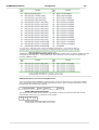
The concept behind FORMS4WORK is based on a modular element system of components. Each
component has connections, so-called ports, using which they can be combined with other components.
If we take the aim of FORMS4WORK as a basis, it can be divides as follows:
· Acceptance of print data
· Processing or emulation of print data
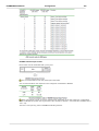
· Transfer of the processed print data
This initially leads to a rough distinction of components and splits all the modules of the system into three
main groups:
Input Interface
The input interface connects the FORMS4WORK system with the host computer. This component makes
the connection to the host computer or a data source using the hardware ports of the FORMS4WORK
system.
Possible ports include the following
· Network (for example Ethernet, Token Ring, SNA)
· Hardware options (for example channel adapters)
Emulation
This is where the print data are prepared for the output device.
Output Interface
When the print data has been processed by the emulation or passed through, they are passed on to the
output device using this component. In this case, too, the connection is made using the hardware ports of
the FORMS4WORK system.
FORMS4WORK Manual
4.2
Principles
10
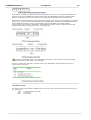
The Standard Application
The standard application of FORMS4WORK can be based on one component from each of the three main
groups:
· Input Interface
· Emulation
· Output Interface
The example describes the easiest way of outputting print data from a host computer on a printer using
FORMS4WORK. The following components are used for this purpose.
Input Interface
The input interface connects the FORMS4WORK system with the host computer. This component makes
the connection to the host computer or a data source using the hardware ports of the FORMS4WORK
system.
Possible ports include the following
· Network (for example Ethernet, Token Ring, SNA)
· Hardware options (for example channel adapters)
Emulation
This is where the print data from Host and/or network are prepared for the output device (e.g. PCL b/w
printers, PDF color printers, Internet, file, etc.).
Output Interface
When the print data have been processed by the emulation, they are passed on to the output device using
this component. In this case, too, the connection is made using the hardware ports of the FORMS4WORK
system.
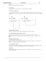
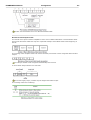
4.3
Input Interface In Detail
Depending on the type of port used, an Input Interface may be made up of several components. One
example of this is an Input port that receives print data with the PPD/PPR protocol via TCP/IP.
In this case the input interface, which we have previously regarded as a single entity, consists of a
transport component, namely the TCP/IP network protocol and the communication component, e.g. the
PPD/PPR protocol.
What components are offered or supported by the various input interfaces depends mainly on the
hardware port of the FORMS4WORK system that is used by the input interface.
Protocols for communication, however, are one of the most important types of components. These are
regarded in the FORMS4WORK system as a property of the input interfaces.
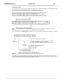
4.4
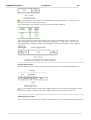
Emulation In Detail
An Emulation generally converts print data from one standard language - for example IPDS - into another
standard language - for example PDF. To allow as many applications as possible to use this facility, there is
an option to process the data using so-called Filters before and / or after the actual Emulation.
In other words the emulation component can be split into Pre Emulation Filter (= Input Filter), Emulation
and Post Emulation Filter (= Output Filter).
FORMS4WORK Manual
Principles
11
Examples of filter components include
·
·
·
·
Stringchange filter
Conditional Stringchange filter
Codepage Filter
Recordchange Filter
Special filters are:
· Barcode Filter
· Overlay Manager
Filters can be linked arbitrarily, in other words Input Filters A and B can be used as follows:
· A-B or B-A, the data pass through both filters in sequence
· A-B-A-B, it is possible to repeat the filters in the data flow
· A-B-C-D-etc., no limit to the number of filters used
The same applies, naturally enough, for Output Filters.
4.5
Output Interface In Detail
Output interfaces may be made up of several components, depending on the type of port used.
FORMS4WORK knows DOS devices, Files, TCP/IP with/without LPR protocol, SMTP, Printers and Fiery as
possible output interfaces.
What components are offered or supported by the various output interfaces, depends, as with the input
interface essentially on the hardware port of the FORMS4WORK systems that is used by the output
interface.
Protocols for communication are also regarded as a property of the output interfaces in the FORMS4WORK
system.
Another property of output interfaces is spooling. This is similar to the Protocol, and as such represents a
component of the output interfaces, which can be enabled or disabled as required.
4.6
Variable Configuration
The simple application is not always sufficient, but the concept of FORMS4WORK allows all components to
be combined almost arbitrarily.
4.7
Processes And Threads
The efficiency of a FORMS4WORK system is primarily dependent on the hardware. Nevertheless the
efficiency is also influenced by the configuration. FORMS4WORK is not just a program that is active on the
system, but is consists of a number of modules, as described in the section Components.
The operating system distinguishes between processes and threads when it allocates processor time. A
process corresponds to an application program that has been started, which in turn can start several
threads for the parallel processing of data.
All the configurations described above within a FORMS4WORK system can be configured in one process,
the Print Process.
This Print process uses several threads during its processing of print jobs. For example, several print jobs
that arrive at the same time are processed in parallel in several threads.
The efficiency of a process falls with the number of threads, however, and therefore, if a large amount of
printing has to be completed, it may be beneficial to distribute the whole print control over several
FORMS4WORK Manual
Principles
12
processes to achieve greater performance.
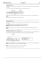
4.8
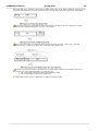
Specimen Application
The Situation
A global company (automobiles) is using IBM IPDS printers and wants to replace them with modern
network printers and high performance b/w printers.
The Problem
The new b/w printers process PCL data and must be connected to an Ethernet network. The host
applications, on the other hand, produce IPDS data.
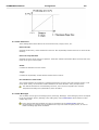
The Solution
FORMS4WORK provides the link between the host and the network printer in the form of a bridge. The
IPDS to PCL emulation allows the print data to be converted between the two printer languages. As a
result of the module structure of FORMS4WORK, two 110-page b/w printers can be used, and if necessary
other printing systems can also be added.
5
Program Components
5.1
System Service
The system service is the core part of the FORMS4WORK. It is used as an interface between the various
program components.
In Windows NT/2000/XP it is permanently available. It receives the commands from the Client application
through TCP/IP and sends them on to the print processes which it must start (emulation and input/output
interfaces). The system service must also serve the opposite route for status messages, error outputs and
dump information.
5.2
Print Process
The Print Process describes the processing of a print job within the FORMS4WORK print system. A Logical
Printer within a Print Process defines three distinctive yet inter-related components as follows:
· Input interface receives the print job from the sender (host computer),
· Emulation translates the print job from one printer language to another (e.g. IPDS to PCL5),
· Output interface transfers the final print job to the receiver (print server, printer, file).
5.3
FORMS4WORK reference
5.3.1
Starting FORMS4WORK and logging in
To start the FORMS4WORK, click the Windows Start button and choose FORMS4WORK from the Programs
menu; or, if you have created a shortcut to the FORMS4WORK application, double-click the FORMS4WORK
icon on the desktop.
Before you can monitor or administer FORMS4WORK, you must log in to the server using the
FORMS4WORK client software. By default the FORMS4WORK client software is installed on the same
FORMS4WORK Manual
Program Components
13
system where the FORMS4WORK server resides. However you can also install and run the client software
on a remote Windows workstation (default for the Linux version).
Connecting to a server
Access levels
Logging in
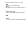
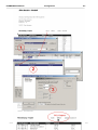
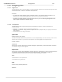
5.3.1.1
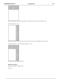
Connecting to a server
To connect to the FORMS4WORK server
1.
2.
3.
4.
5.
Double-click the FORMS4WORK icon on your desktop, or click Start, choose Programs, then
FORMS4WORK, and then FORMS4WORK. The Connect to FORMS4WORK Server dialog box appears.
Select a FORMS4WORK Server from the server list.
Click on the appropriate access level button.
Enter the password assigned to you by the administrator, and click Connect.
The FORMS4WORK user interface appears.
Server List
Displays the list of the available FORMS4WORK servers found in the same LAN (in this particular case in
the same IP subnet) and which are running.
Password
Access to a FORMS4WORK server can be restricted by means of three passwords. In this way the access
levels to the server are controlled dependent on the password given when logging in.
Connect
Click this button after you have selected a server from the server list.
Add...
Enter DNS name or IP address.
The Add button opens the Add Server dialog box where you can add an additional server to the server list.
Enter the domain name or IP address for the server that couldn't be found automatically. See Connecting
to a server for more information.
Remove
Remove selected server from server list.
The button will be disabled if you select a server that is currently connected or has been found
automatically.
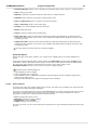
5.3.1.2
Access levels
The FORMS4WORK server software provides the choice of three access levels:
Administrator, Operator and Guest.
Administrator
Administrator access allows full management of the FORMS4WORK, including setup and configuration of
print processes as well as starting, ending, and monitoring of printing jobs. Administrator access is only
available on one computer at a time.
FORMS4WORK Manual
Program Components
14
Operator
Operator access allows starting, ending, and monitoring of printing jobs. As Operator, you can cancel or
restart printing jobs.
Guest
Guest access allows monitoring of printing jobs only.
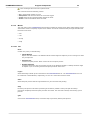
5.3.1.3
Logging in
Connect
Click this button after you have selected a server from the server list.
Add...
Enter DNS name or IP address.
The Add button opens the Add Server dialog box. In this dialog box you can add additional FORMS4WORK
server to the server list. If you do not automatically find a server in the list, you can manually add the
server DNS name or its IP address. See Connecting to a server for more information.
Remove
Remove selected server from server list.
The button will be disabled if you select a server that is currently connected or has been found
automatically.
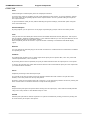
5.3.2
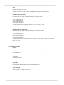
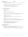
The FORMS4WORK Client Software
The FORMS4WORK client application main window is displayed the first time a connection to the
FORMS4WORK server is established. The main window displays the following sub-windows:
The Upper Window
The upper window displays the logical printers currently configured for this server.
The following describes the buttons at the top of the main window:
· Start Logical Printers Clicking this button starts the printing process. The Job List window appears.
You can not add or remove a logical printer.
· Stop Logical Printers When enabled, the Stop Logical Printers icon shows red. Click the button to stop
the printing process.
· Edit Logical Printer With a printer name highlighted, click this button to access the Edit Logical Printer
window, where you can edit properties for each of the characteristics of the printer.
· Add Logical Printer Click this button to add a new logical printer.
· Remove Logical Printer With a printer name highlighted, click this button to remove the printer.
The Events Window
The lower part of the main window shows a list of events. Initially, the Event view only shows the time that
the FORMS4WORK Client has been launched.
As soon as a connection has been made to the FORMS4WORK Server, any messages from the server and
its active logical printers will be shown in the Events window. The message color-coding indicates their
order of significance. A difference is made between the following levels:
· Error messages are shown in red.
FORMS4WORK Manual
Program Components
15
· Warning messages are shown in blue.
· Information is issued in black lettering.
· Debug messages are issued in gray.
5.3.2.1
Setup and Configuration
5.3.2.1.1 Server
From the 'Setup' menu select 'Server...' to access server configuration.
Server properties and options refer to the configuration of the FORMS4WORK server which is running as
system service. You must have administrator access to use this function.
You can view or modify
·
·
·
·
Common server settings
Connectivity
Security options
Accounting options
Common server settings
Start Logical Printers at server start
With this option enabled, as the FORMS4WORK Server starts, it will automatically activate the currently
configured Logical Printers.
Default: disabled
after a delay of
Used to delay the automatic start of Logical Printers by x number of seconds. Delaying the start of Logical
Printers might be necessary if more time is needed to load device drivers required by the FORMS4WORK.
Default: 0 seconds (no delay)
Restart not responding Logical Printers
Enabling this option will cause the FORMS4WORK to attempt to recover lost connections. If communication
with a print process and its Logical Printers is lost, the FORMS4WORK Server will attempt to re-establish
the connection.
Default: disabled
Size of event log files
Define maximum size of event log file (in kilobytes).
Default: 2048 KB
Connectivity
Server Address
Leave blank when the Print Server which runs FORMS4WORK server has only one IP address. If multiple IP
address's are used, enter the local IP address or DNS name of the network interface which is to be used
by FORMS4WORK server.
If you enter an IP address for this option and the Print Server's IP address changes at a later time.
You will lose communication with the FORMS4WORK Server. This option will need to be updated if the
Print Servers IP address changes.
FORMS4WORK Manual
Program Components
16
Port
Currently used TCP/IP port address.
For internal communication the FORMS4WORK server and client use the TCP port address 49110.
Default: 49110 (not changeable)
Timeout
Set timeout for communication between server and print processes.
If the FORMS4WORK server is heavily stressed, print processes might be displayed as not responding.
Increase this value to resolve this.
Default: 5000 milliseconds
DNS available
Enable if DNS is available in the network.
If enabled, DNS is used to resolve names to IP addresses.
If enabled although DNS is not available, system performance will be decreased.
Default: disabled
Security
The FORMS4WORK server software provides the choice of three access levels:
Administrator, Operator, and Guest.
Administrator Password
Enter password for administrator access.
Administrator access allows full management of the FORMS4WORK, including setup and configuration of
print processes as well as starting, ending, and monitoring of printing jobs. Administrator access is only
available on one computer at a time. You should have Administrator access on the Fiery.
Operator Password
Enter password for operator access.
Operator access allows starting, ending, and monitoring of printing jobs. As Operator, you can cancel or
restart printing jobs.
Guest Password
Enter password for monitoring access.
Guest access allows monitoring of printing jobs only.
By default, no passwords are set on the FORMS4WORK. If you do not specifically set passwords, all
users will have administrator privileges, which include access to important functions such as Setup
(including setting passwords), and job control. We strongly recommend that you set at least an
Administrator password to protect FORMS4WORK from random or accidental changes to Setup.
FORMS4WORK Manual
Program Components
17
Accounting
Active
When checked, the FORMS4WORK accounting system is activated and all jobs are processed within the
accounting system.
Retrieve Popup address from DNS
If the username of a print job does not correspond to the account name of the user, the address of the
Popup Tool may not be determined. Use this option to resolve the username by DNS. Only use this option,
if usernames can be resolved by DNS without errors. Otherwise DNS requests may take some time and
decrease the performance of the FORMS4WORK printing system.
Notify user when job has been printed
The user will be notified if the job has been printed successfully. This function is only available if the user
address is known by FORMS4WORK. This depends on the configuration and the input ports used. For
displaying the notifications the Accounting Popup Tool must be running on the printing client.
Notify user when printing failed
The user will be notified if the job could not be printed. This function is only available if the user address is
known by FORMS4WORK. This function is only available if the user address is known by FORMS4WORK.
This depends on the configuration and the input ports used. For displaying the notifications the Accounting
Popup Tool must be running on the printing client.
Find server automatically in network
If checked, the accounting server will be searched automatically by UDP broadcasts in the network.
Specify an address if you have more than one accounting server in your network or if the server can not
be reached by UDP broadcasts.
Connect timeout
Timeout in seconds to connect to the accounting server
Communication timeout
Timeout in seconds for communication with the accounting server
Idle timeout
The connection to the accounting server is dropped after the specified number of seconds.
Password
If a password has been setup at the accounting server it has to be entered here. Otherwise leave it blank.
Accounting must be installed separately and has to be licensed.
5.3.2.1.2 Print Process Options
Print process properties and options refer to the configuration of its common settings and event logging
behavior.
You must have administrator access to use this function.
FORMS4WORK Manual
Program Components
18
Common print process settings
Name
Define name of the print process.
Max. Concurrent Jobs
Enter maximum number of concurrent jobs.
This value limits the number of print jobs that can be processed at one time by the print process. If Job
Splitting is enabled, you might want to set this value to "1" to ensure job integrity. You might also change
this value if the print process has to process very large and complicated print jobs or if a very large
number of small print jobs occur at the same time.
Default: 0 (unlimited)
Delay job output
Define delay in job output.
If 'Max. Concurrent jobs' is set to 1, it is possible to define a delay in milliseconds which the print process
should wait after closing one job and before opening the next.
Default: 0 milliseconds
Log levels
Do not use event logging for this print process
Set if you do not want the print process events to be logged.
Log event entries for
The following options are available for event logging:
· Error messages: Logs messages which occur while processing a print job. These are displayed in red
in the Events Window. Error messages are always logged (default: enabled).
· Warning notes: Enable to log warning notes. Warning notes may require intervention and are shown in
blue (default: enabled).
· Basic information: Enable to log basic information. Displays basic job information in the Events
Window. These messages are displayed in black (default: enabled).
· Extended information: Enable to log extended information. Displays extended job information in the
Events Window. These messages are displayed in black. This information is more detailed than the
basic information (default: enabled).
· Debug information for troubleshooting: Enable to log debug information for troubleshooting. Use
only for program diagnostics. It is displayed in gray (default: disabled).
Depending on how many options you select, the volume of outputs of a log file and in the Events
Window will increase or fall. The use of debug information drastically reduces the processing speed of
print jobs and may even lead to rejection of print jobs.
FORMS4WORK Manual
Program Components
19
5.3.2.1.3 Logical Printers
Logical Printers allow print jobs that arrive at input port interfaces to be distributed to certain emulations
and output port interfaces. All defined Logical Printers are listed in the Logical Printers list in the main
window of the FORMS4WORK client.
The Logical Printers list contains all defined Logical Printers. In the simplest case, the Logical Printer list
contains a single Logical Printer which assigns all print jobs from one input interface to one emulation for
data conversion and one output to print the data.
Edit logical printer...
To edit the Logical Printer double click a selected row in the list or click the 'Edit Logical Printer...' button
allows.
Add Logical Printer...
Click 'Add Logical Printer' button or select 'Add Logical Printer...' from the 'Setup' menu to add a Logical
Printer (a new row) to the list.
Remove Logical Printer...
Click 'Remove Logical Printer' button or select 'Remove Logical Printer...' from the 'Setup' menu to remove
a Logical Printer (the highlighted row) from the list.
Input interface
Shows the type and properties of the input port interfaces and also its description. Used to configure the
input port for incoming print data.
Input Filter
Shows the input filters. Input filters compensate incompatibilities between the host and destination printing
system or incorrectly formatted commands of character strings before the conversion.
Data conversion
Shows the name of the assigned emulation for data conversion (e.g. IPDS to PCL5) and also its
description. Each emulation generally has different settings.
Output Filter
Shows the output filters. Output filters compensate incompatibilities between the host and destination
printing system or incorrectly formatted commands of character strings after the conversion.
Output interface
Shows the type and further properties of the assigned output port interface and also its description. Used
to configure the output for outgoing print data.
Edit Logical Printer
To edit a Logical Printer, double click on a selected row of the Logical Printers list or click the 'Edit Logical
Printer...' button above the Logical Printers list.
The 'Edit Logical Printer' window allows to edit the logical printer, consisting of:
FORMS4WORK Manual
·
·
·
·
Program Components
20
Input Interface
Condition of usage
Emulation
Output Interface
Input Interface
The required input interface for the print job is to be selected here. The list contains all the existing defined
by the user.
Condition of usage
In keeping with the selected condition, the required criterion is to be selected or entered here.
Emulation
The required emulation for the print job is to be selected here. The list contains all the existing defined by
the user.
Output Interface
The required output interface for the print job is to be selected here. The list contains all the existing
defined by the user.
Destination/Device
· Default device as configured in output port
No specific destination address is to be defined; instead the default destination defined in the output is to
be used.
· Device as delivered by protocol
Some input protocols supply a destination address in the data stream, at which the data are to be output.
If, for example data are received using the LPD/LPR protocol, the data stream contains the name of the
destination printer. If this is the actual name of the destination printer, it may be used. The destination
device at which the print job is finally output is therefore not decided until the system is running.
If the destination address supplied by the protocol is a virtual output device that does not really exist. this
option should not be selected. In this case, by selecting 'Default device as configured in output port' the
default destination defined in the output must be used or another destination chosen by selecting 'Specific
Device'.
· Specific Device
If this rule has been assigned to a specific output device, its name is displayed here. If a print job takes
this route, the destination address defined in the output is overwritten and replaced by the name defined
here. Depending on the output type you have selected, the appropriate destination address can be defined
here.
File port – Definition of a file name
DOS device – Definition of a port, for example COM1:
Printer – Definition of a printer that must be installed in Windows
TCP/IP port – Definition of an IP address and IP port number
If, for example, the output is a file port, the name of the output file can be defined here. The file name
defined in the file port is then ignored.
Use as default
FORMS4WORK Manual
Program Components
21
If this Logical Printer is to be used as the default printer for all print jobs that do not comply with a
criterion, this option is to be activated.
Only one Logical Printer can be marked as the default.
Test Logical Printer
A test job can be used to check the configuration of an emulation against the real printer. Additionally, by
sending a test job to the printer or the attached output port interface, it is possible to test the
communication between the output interface and the printer. There is no host system required while
printing a test job.
While in started state, select one of the listed test jobs. This job will be processed as soon as you press the
button 'Print'.
You can repeat this step as long as you do not leave this dialog using the 'Close' button.
5.3.2.2
Run conversion and job monitoring
Start
Click 'Start' button or select 'Start' from the 'File' menu to start FORMS4WORK. After it has been started
successfully, FORMS4WORK will be able to receive print jobs for data conversion.
While running in conversion mode, Logical Printers can only be viewed, but not edited nor added nor
removed.
Stop
Click 'Stop' button or select 'Stop' from the 'File' menu to stop FORMS4WORK from receiving print jobs.
In order to edit, add or remove a Logical Printer, the job conversion process must be stopped.
View Logical Printer
Click 'View Logical Printer' to view a Logical Printer. Select one from the list.
5.3.2.2.1 Job list
The Job list window is used to monitor and to manage print jobs. The list includes print jobs which are
waiting to print or they already have been printed. For every item in the list further information is
available:
· Name: shows job name. The name is extracted from the job itself or automatically created by
FORMS4WORK.
· Status: shows job status. Possible entries are: Deleting, Error, Canceled, Printed, Printing (Byte), Held,
Spooled, Connecting, Emulating, Receiving. Those entries can be added by: Paused, Delayed, Delayed
until (Date, Time), Kept.
· Converted: shows number of converted pages.
· Printed: shows number of printed pages.
· Size: shows size of print job.
· Created: shows when print job has been created.
Job management for spooled jobs is available after selection via the context menu or the job menu. It is
FORMS4WORK Manual
Program Components
22
possible to pause the printing of a job, to continue printing, to abort or re-start the print job.
Detailed information for a selected job are shown in the job properties frame on the right hand side.
Active Jobs
For every item in the Active Jobs list the following information is available:
· Name: shows job name. The name is extracted from the job itself or automatically created by
FORMS4WORK.
· Status: shows job status. Possible entries are: Deleting, Error, Canceled, Printed, Printing (Byte), Held,
Spooled, Connecting, Emulating, Receiving. Those entries can be added by: Paused, Delayed, Delayed
until (Date, Time), Kept.
· Converted: shows number of converted pages.
· Printed: shows number of printed pages.
· Size: shows size of print job.
· Created: shows when print job has been created.
Job management for spooled jobs is available after selection via the context menu or the job menu. It is
possible to pause the printing of a job, to continue printing, to abort or re-start the print job.
Detailed information for a selected job are shown in the job properties frame on the right hand side.
Printed Jobs
For every item in the Printed Jobs list the following information is available:
· Date/Time: shows the date and time when the job has been completely printed.
· Name: shows job name. The name is extracted from the job itself or automatically created by
FORMS4WORK.
· Status: shows job status. Possible entries are: Deleting, Error, Canceled, Printed, Printing (Byte), Held,
Spooled, Connecting, Emulating, Receiving. Those entries can be added by: Paused, Delayed, Delayed
until (Date, Time), Kept.
· Pages: shows number of printed pages.
· Printed: shows number of printed pages.
· Size: shows size of print job.
· User: shows name of the user (client) who has printed the job.
Detailed information for a selected job are shown in the job properties frame on the right hand side.
5.3.2.2.2 Job Properties
Job Properties
The job properties window is a dynamic status display of the job currently selected in the job list frame.
Besides the core job information, as its name, type, size, creation time and ownership, there are further
dynamically updated information about its state and available actions.
To view and modify the properties of several jobs at once, highlight the respective jobs.
Depending on its status, the following actions are applicable for one or more jobs:
· Print: (re-)print the spooled job(s)
FORMS4WORK Manual
Program Components
23
· Advanced Reprint: Reprint some or all pages of the spooled job(s) and/or redirect it to other printers
· View: viewing of job data
· Redirect: redirection of jobs from the last used device to a different device.
· Schedule: delay output of a print job to a specific date / time
· Pause / Undo Pause: pause or continue processing the job(s)
· Keep / Undo Keep: keep or remove the job(s)
· Printed: set or remove attribute 'printed' of the job
· Delete: delete the job(s)
· Cancel: cancel processing of the spooled job(s)
· Input Trace File: retrieve the file which contains the captured job data before the data have been
converted by the emulation. This action is only available if the Data Monitoring option was active while
processing job data.
· Output Trace File: retrieve the file which contains the captured job data after the data have been
converted by the emulation. This action is only available if the Data Monitoring option was active while
processing job data.
Only the actions are shown that can currently be applied.
Advanced Reprint
Define the pages of the job to reprint it or to send it to the original printer or an other destination or
printer.
In the page ranges table first define a range starting with From Page and ending with To Page for the
destination or printer. Depending on this range you can select an other printer to print the pages before
the range start and to print the pages after the end of the range. Select <Skip> in the
Destination/Printer column, if you do not want to print a range of pages.
Requirements for Advanced Reprint:
· Output Spooling must be enabled
· Login as Administrator or Operator
· Only available for PCL or ASCII data. Input Data Type Recognition must be enabled in Input Port to
detect data as ASCII or PCL
· If using the Raw-Emulation the option Count Pages must be enabled.
5.3.2.3
Event view list
The lower part of the main window shows a list of events. The Event view list initially only shows the start
time of the client after starting the application
As soon as a connection has been made to a FORMS4WORK Server, all the messages of the server and its
active print processes will be shown in this frame. The message color coding indicates their order of
significance. A distinction is made between the following levels:
·
·
·
·
Error messages are shown in red.
Warning messages are shown in blue.
Information is issued in black.
Debug messages are issued in gray.
See also Log Levels. You can control the types of messages to be given through the properties of the print
process.
FORMS4WORK Manual
Program Components
24
More messages also mean more system stress.
The event list shows the following criteria:
·
·
·
·
5.3.2.4
No.: Incremental number of event
Date/Time: Date and time when the event was logged
From: Name of the component which logged the event
Event: Textual information about the event
Menus
The main menu in the FORMS4WORK Client window contains the entries shown below which display menus
with further entries. Frequently required menu actions can also be reached directly through the button bar
below the main menu.
· File
· Job
· Setup
· Help
5.3.2.4.1 File
New...
Creates one (more) of the following:
·
Client Window
Opens new client window. An additional client window might be helpful if you are running more than
one print process.
·
Print Process
Creates new print process. Enter a name for the new print process.
·
Desktop Shortcut
Creates a shortcut for the current print process on the Windows desktop. A desktop shortcut might
be helpful if you are working with several print processes at the time.
Login...
Starts the dialog to build up the connection to the FORMS4WORK Server. The FORMS4WORK Server can
be monitored or administrated, respectively, as soon as a connection has been made.
Start
Starts the print process with its Logical Printers for job conversion and printing.
Stop
Ends the print process. No further processing of the data is possible. Active print jobs are always
processed completely before the print processes are ended. This can lead to delays when ending a print
process.
Quit
Closes down FORMS4WORK Client, but doesn't stop a previously started print process.
FORMS4WORK Manual
Program Components
25
5.3.2.4.2 Job
Print
Starts sending the selected print job to the output port interface.
As soon as the output is complete, the job will be deleted from the spooler. To prevent deletion, activate
the 'Keep' option in the spooling options of this output interface. This is a general setting for all jobs on
this output interface.
To prevent deletion of this job only without affecting the general settings, activate this option using the
menu command 'Keep'.
Advanced Reprint
By using Reprint you can print some or all pages of spooled job(s) and/or redirect it to other printers
View
View job data. PCL and ASCII jobs will be viewed as Portable Document Format (PDF) files. This requires
add-on software. Adobe® Acrobat® Reader™ is free software that lets you view and print PDF files. It can
be downloaded directly from the Adobe website.
None PCL/ASCII jobs will be viewed in a special window containing a hexadecimal and ASCII display
region.
Redirect
You can redirect the selected job(s) from the last used device to a different device. Redirection is available
for spooled jobs only.
Schedule
The setting Print at offers a way to delay output of the print job to a specific date / time. The job is held
until the specified date / time is reached.
By choosing Print as soon as possible, the print job will be delivered when its output port is not occupied.
To print a job manually, the option Hold must be selected. This means that the print job is not output until
you select the Print command.
Pause
Suspends processing of the selected print job.
The job will not be sent to output even if the therefore defined time has reached. The job will not be
deleted, even if the preset time to keep has passed.
If Pause is reset, the processing of the job is resumed, i.e. the job will be printed if its time for printing has
been reached earlier or deleted if the time to keep has already passed.
Keep
Keeps selected print job in the spooler after sending it to the output port, until it will be manually deleted
using menu entry 'Delete' or the attribute 'Keep' is reset.
Printed
Selected print jobs will be marked as printed. If a job was scheduled for printing, its time for printing will
be reset and the job is kept in the spooler.
FORMS4WORK Manual
Program Components
26
If Printed is reset, the job will be marked as 'Held, kept'.
Cancel
Stops processing of the selected print job. The 'Keep' attribute of a spooled job will be set automatically.
Delete
Stops output of the selected print job and deletes it. This function is available for spooled jobs only.
5.3.2.4.3 Setup
Edit Logical Printer...
Opens the 'Logical Printer' dialog for editing.
See edit Logical Printer.
Add Logical Printer...
Creates a new Logical Printer.
Click 'Add Logical Printer' button or select 'Add Logical Printer...' from the 'Setup' menu to add a Logical
Printer (a new row) to the list.
See add Logical Printer.
Remove Logical Printer...
Removes the highlighted Logical Printer(s).
Click 'Remove Logical Printer' button or select 'Remove Logical Printer...' from the 'Setup' menu to remove
a logical printer (the highlighted row) from the list. This may be necessary to add a new logical printer
component.
Print process
Opens Print process options.
See print process.
You must have administrator access to use this function.
Server
Opens Server options.
See server.
Backup
Saves or restores a complete configuration of a FORMS4WORK Server.
The backup includes a ZIP compatible archive file of the entire configuration of the server and all log files.
FORMS4WORK Manual
Program Components
27
5.3.2.4.4 Help
Index
Opens the FORMS4WORK online help with the index for information search by keywords.
Info
Displays version and copyright information for the FORMS4WORK application. Click on information window
to return to the program.
5.3.2.5
Icon Bar
Gives fast access to the most important commands:
·
·
·
·
·
·
·
5.3.2.6
Start Print Process
Stop Print Process
Edit Logical Printer
Add Logical Printer
Remove Logical Printer
View Logical Printers
Watch Print Devices
Print Process Bar
Shows the current print process with its Logical Printers and allows fast access to a print process via pulldown menu.
Choose one print process from the list and click "Go" to go to the chosen print process.
5.3.2.7
Watch Print Devices
The Print Device window is used to monitor printers as output devices, which are used by FORMS4WORK
to process the print jobs. The required information can be gained by
· SNMP (Simple Network Management Protocol) with continuously polling of the printer or by
· PJL (Printer Job Language) messages send by the printer during the printing of a job.
The way used to gain information from the output devices is set at the Output Port Interfaces
configuration.
In the windows list each printer is displayed as an item with a symbol. The color of the symbol indicates
the printers state.
·
·
·
·
Green
Yellow
Red
White
The printer is available and ready
Warning, i.g. low of paper
Not available because i.g. offline
Unknown or not available
The state of a printer is detected by existing or missing state information delivered by the printer. States
like i.g. 'low paper', 'out of paper', 'low toner', 'out of toner', 'door open', 'paper jam' and 'service required'
can be signaled by the printer. If multiple conditions are signaled by a printer, the color of the printers
symbol is signaling the most critical condition. If a printer i.g. signals 'low paper' (warning) and 'out of
toner' (error), the symbol will be displayed in red color. If a printer signals 'low paper' (warning) and 'low
toner' (warning), the symbol will be displayed in yellow color, because both conditions are warnings.
By double clicking a list entry, depending on the selected type of device monitoring, further information
about a printer will be shown in a separate dialog. Printers monitored by SNMP are responding with a
manufacturer dependent subset or all of the following types of information:
FORMS4WORK Manual
Program Components
28
Information
Description
IP Address
IP address, assigned to the printer.
MAC Address
MAC address of the printers network interface.
Hostname
Name, assigned to the printer for DNS resolution.
Model Type
Manufacturer dependent model type description.
System Location
Location of the printer.
System Contact
Email contact of the printers administrator.
Impressions
Number of printed impressions during lifetime or since last power on of the printer.
Running since
Time when the printer was powered on.
Input Trays
The amount of paper available in the paper trays. Amount of paper is given in
remaining percent as far as the printer is supporting this type of information.
Markers
The amount of toner available at the printer. Amount of toner is given in remaining
percent as far as the printer is supporting this type of information.
Printers monitored using PJL do not deliver a unique structure of information. The amount and extent of
information depends on manufacturer and model type.
6
Configuration
6.1
Introduction
Set up the FORMS4WORK Server
1. In the Main Window of the Client, open 'Setup' menu.
2. Click 'Server...'.
3. In the dialog configure the server options.
Set up a Print process
1. In the Main Window of the Client, open 'Setup' menu.
2. Click 'Print Process...'.
3. In the dialog configure the print process options.
Set up a Logical Printer
Define the Logical Printers using which the dispatcher distributes print jobs received by the FORMS4WORK
system. The configuration dialog contains several sections that are described in detail in the following:
· Input Interface: allows you to add and set up the required input port interfaces for a Logical Printer
within a print process.
· Input Filter: select and configure the input filters.
· Data Conversion: add and set up the required emulation for data conversion.
· Output Filter: select and configure the output filters.
· Output Interface: select and configure the output port interface.
FORMS4WORK Manual
6.2
Input Interfaces
6.2.1
Overview
Configuration
29
Input interfaces are used as reception ports for print data. FORMS4WORK supports different types of
inputs:
·
·
·
·
·
·
·
·
·
·
·
·
·
·
Channel [ISA]
Channel [PCI]
System Devices
ESCON
Files
LPD
Novell
ODBC
POP3
PPD
SNA LU1/LU3
SNA LU 6.2
TCP/IP / Local TCP
Twain
Parameters that are independent of the input type are described under the point headed Properties.
Special parameters are listed under the relevant input type.
To define a new input
To define a new input interface in the system, select Properties in the context menu of a print process and
go to the dialog page headed Input interface. On this page you can delete existing input interfaces by
selecting Delete or reconfigure them by selecting Configure. By selecting Add, the user can add a new
input interface. A list appears with the available input types, from which the required type must be
selected. After this the configuration dialog for the selected interface type appears automatically.
All the inputs defined in this way are automatically activated and can receive data when the print process
is started. Through which emulation the data pass and to which output they are finally sent is defined in
the Logical Printer editor. In principle there is no direct link between an input and a certain output, but
such a link may be created in the Logical Printer editor where print jobs can be assigned to defined outputs
on the basis of various criteria.
6.2.2
Properties
6.2.2.1
Settings (Input Interface)
Buffer
· Read block size
Enter block size for read operations in KB.
When data are received, the data are read in blocks of the specified size as long as the input port supports
this. With a file port, for example, the data are read and processed in blocks. The larger the block size, the
fewer read access operations are required. A large block size, however, increases the memory requirement
for job management.
Default: 32 KB
· Maximum size of receive buffer
Enter maximum size of the internal data buffer.
If the data that are received cannot be processed because, for example, the printer at the output is busy,
the data are nevertheless accepted and placed in a buffer. This value defines the maximum size of this
buffer. When the receive buffer is full, no more data can be accepted until the data can be processed and
FORMS4WORK Manual
Configuration
30
the buffer is thus emptied. If no value is entered here, the size of the buffer is only limited by the available
hard disk space. This setting is only available if 'Direct Read' is not activated.
Default: none (no entry possible)
· Direct Read
Enable to let the input data stream not be buffered and not be read directly from the input interface.
In most cases this setting will improve performance. If Channel Input is used in conjunction with very
small block sizes, the time needed for storing the data in a buffer would affect performance negatively. In
this case be sure that 'Direct Read' is activated. This setting is only available if no protocol is used.
Default: enabled
Timeouts
· Read Timeout
Enter timeout for data reception.
This value allows the time properties of FORMS4WORK for read operations to be influenced. This value
should only be changed by experienced users.
Default: 50 msec
· Write Timeout
Enter timeout for data output.
This value allows the time properties of FORMS4WORK for write operations to be influenced. This value
should only be changed by experienced users.
Default: 1000 msec
· Delay, if data received
Enter the time in milliseconds that a print job may be delayed in receiving data so that other print jobs can
be completed fluently.
Print jobs that arrive at the same time are processed in parallel. Each print job is allocated a certain
amount of processor time for this purpose, which it must share with other print jobs.
Default: 0 msec
· Delay, if no data received
Enter the time in milliseconds that a print job can be delayed if no data are currently being received for
this print job.
If no data are currently being received for a print job, the print job may be delayed and the available
processor time can be assigned to other print jobs.
Default: 10 msec
FORMS4WORK Manual
6.2.2.2
Configuration
31
Sessions
Maximum of input sessions
Enter maximum number of input sessions.
When this number of sessions has been reached, further connection requests by a host are rejected until
the number falls below the maximum level again. If no value is entered here or if 0 is entered, the number
of sessions is unlimited.
Default: 10
Maximum of pending jobs
Enter maximum number of pending jobs.
When the maximum number of pending jobs has been reached, further print jobs will not be processed. If
no value or 0 is entered here, there is no limit to the number of pending jobs.
If a very large number of print jobs is processed at the same time, this may have a major adverse
effect on the system performance.
Default: 10
Session Timeout
Enter session timeout interval (in seconds).
If no data are received from a connection (for example a TCP/IP session) for a certain time, FORMS4WORK
automatically terminates the connection. This time can be defined here (in seconds). No entry or a 0 in this
field prevents the automatic termination of a connection at the input by FORMS4WORK.
Default: none (empty)
Job Timeout
Enter job timeout interval (in seconds).
If several print jobs arrive at a connection (for example a TCP/IP session) in sequence, FORMS4WORK may
not recognize these as separate jobs. This may cause problems if, for example, the data are to be output
through the PPD/PPR protocol since this protocol must have access to the complete print job before it is
passed on to the printer. Therefore it is necessary to define a job timeout. If no data arrive at a connection
for a certain period of time, the current print job is terminated. All further data that arrives at this
connection will be assigned to a new print job. No entry or a 0 in this box will prevent print jobs from
being split automatically.
Another possibility of splitting a continuous flow of data into individual print jobs is to simulate the end
of the print job after a certain number of pages and to start a new print job with the following pages.
This setting is a property of the emulation that must support it. The appropriate possible settings are
given in the configuration dialogs of the emulations.
Default: empty (none)
Look for session every ...
Enter interval in milliseconds when input port shall monitor the input for receiving data (polling).
A file port, for example, checks the specified directory at regular intervals for new data so that it can then
process them.
Frequent monitoring increases the workload of the computer. The value should therefore not be made
too low. A higher value will only mean that a received job is identified a little later, so it is quite
FORMS4WORK Manual
Configuration
32
acceptable for this value to be several seconds.
Default: 1000 msec
Job start sound
Define a job start sound.
At arrival of a print job a sound can be played. Therefore the name of a sound defined in the Control
Panel, a wave file or '-1' for a short signal can be entered here. Leave this field empty for no sound.
Default: empty (no sound)
6.2.2.3
Data (Input Interface)
Decompress and decrypt data automatically
Enable to let FORMS4WORK decode compressed or encrypted data automatically that comes from another
FORMS4WORK system.
Default: disabled
· Password
Enter password used by the other FORMS4WORK system.
Use job information within data stream
(when receiving data from a FORMS4WORK output interface)
Enable to let the input interface interpret additional job information.
If data is received from a FORMS4WORK output interface, additional information about a job (e.g. job
name) can be transferred before the print data. If this option is enabled, the input interface interprets this
information. To use this feature, the corresponding option of the output interface must also be checked.
Default: disabled
6.2.2.4
Data Type
Input Data Type Recognition
Active
Enable to either determine the type of the incoming data automatically or assign it manually to the data
stream.
Default: disabled
· Always Assume
Set input data type to a certain incoming data stream.
If the type of the incoming data stream is known, there is no need to use the automatic detection. The
data type can be set manually to a fix value here.
Default: disabled (only available when Active is enabled)
· Auto Detect
Select input data type(s) that shall be detected automatically.
FORMS4WORK Manual
Configuration
33
The data type of the incoming data will be recognized automatically. Several types can be selected, for
which the incoming data is tested. Because under some circumstances the real data type might not be
recognized for sure, unused data types should be turned off to avoid misleading detection.
Default: disabled, no data tape selected (only available when Active is enabled)
6.2.2.5
Data Capturing (Input Interface)
Data Capturing
Data capturing allows to write incoming data to a file before the data is converted by the emulation. This
feature should only be used for testing purposes because it slows down the system performance.
Active
Enable to log sent data.
Default directory for the log file is [FORMS4WORK application path]\DATA\DSPPATHx, default name of the
log file is Ixxxx.DAT. Each job is placed in a separate file.
Default: disabled (not active)
· Without protocol data / With protocol data
Set if you want the protocol data to be saved to the log file, too.
Default: Without protocol data
· Maximum files to capture
Define the maximum number of files to be captured.
If the specified maximum number of files is reached, older files will be overwritten.
Default: 99
· Maximum size (MB)
Define the maximum number of megabytes per job to be captured.
Default: 0 (unlimited)
Maximum hours to keep
Files will be deleted after the specified number of hours.
Default: 720
· Add job name to captured filename
Enable if you want the job name to be added to the captured filename.
The job name will be added in parenthesis to the captured filename.
Default: enabled
FORMS4WORK Manual
6.2.3
Configuration
34
Channel [ISA]
The selection of a Channel as an input interface open up a dialog with the following tabs:
Channel Input Device
Settings
Sessions
Data Type
Data Capturing
You can choose between 2 channel input devices.
6.2.3.1
Channel [ISA] (Input Port)
A channel input device must be installed on your FORMS4WORK server in order to work with this
interface. To install device, execute ChannelInput.exe from the FORMS4WORK software package.
Options
Printer Emulation
Select a printer emulation from the pull-down menu.
Available printers are: IBM 3211, IBM 3825 (IPDS), IBM 4245, IBM 4248, IPDS Bridge, SNI 3338, SNI
3348, SNI 3365
Default: IBM 3211
This menu allows to select the type of printer which will be emulated by FORMS4WORK to the connected
host on the channel interface.
The printers IBM 3211, IBM 4245, IBM 4248, SNI 3338/39 and SNI 3348 are fanfold impact printers which
are equipped with exchangeable print bands.
The IBM 3825 is an IPDS printer. When using this emulation, the channel card makes a 'normal printer
restart' after the start of the channel driver.
The IPDS Bridge works with the IBM 3825 driver but makes no 'normal printer restart' after the start of
the channel driver.
The printer SNI 2050/2075/3365 are cut sheet laser printing systems which are able to print
simplex/duplex from several paper trays and to stack the paper into different output trays. Besides those
printers are able to use different fonts, forms and overlays when the required resources are stored on the
printers' hard disk drive before.
Channel Address
Enter channel address in hexadecimal code.
The channel address identifies the byte address of the emulated printer which is used with channel
protocol.
Default: AE (hex) for device 1, AF (hex) for device 2
Channel Timeout
Set timeout of the channel input device (in seconds).
Possible values: 0 - 300 sec
Default: 45 seconds
Don't stop channel input service when stopping print process
FORMS4WORK Manual
Configuration
35
Enable to keep from stopping the channel input service when stopping a print process.
When enabled, the Windows NT device will not be automatically stopped when closing the input interface.
If you are using two Channel Input devices, it is recommended to use this option for starting and stopping
the devices independently.
Default: disabled (single device), enabled (two devices)
Ignore suppress out
Enable to ignore the 'suppress out' signal.
With channel connection there is a signal called 'Suppress Out'. The host computer is using this signal to
inform the device that it should not activate the 'Request In' signal by itself. The 'Request In' signal usually
is used by the device to inform the host computer about a pending state message.
If 'Suppress Out' is set by the host, the host informs about the inconvenience of state messages. Using the
'Ignore suppress out' switch may change the behavior of the FORMS4WORK Channel Input concerning the
'Suppress Out' signal set by the host computer.
Default: disabled
Strip channel commands
Enable to strip channel commands.
This switch controls whether PCC bytes (PCC = Printer Control Character), i.e. control commands for line
feed and form feed, are passed to the emulation by the Channel Input or not. The Channel Emulation and
the X-Metacode to PCL emulation are in need of these PCC Bytes, the IPDS to PCL emulation does not
know about them because line feeds and form feeds are already present in the IPDS data.
Default: enabled
see also Settings
6.2.4
Channel [PCI]
The selection of a Channel as an input interface open up a dialog with the following tabs:
Channel Input Device
Settings
Sessions
Data Type
Data Capturing
You can choose between 2 channel input devices.
6.2.4.1
Channel [PCI] (Input Port)
A channel input device must be installed on your FORMS4WORK server in order to work with this
interface.
Driver settings
Channel Timeout
Set timeout of the channel input device (in seconds).
FORMS4WORK Manual
Configuration
36
Possible values: 0 - 300 sec
Default: 45 seconds
Don't stop channel input service when stopping print process
Enable to keep from stopping the channel input service when stopping a print process.
When enabled, the Windows NT device will not be automatically stopped when closing the input interface.
If you are using two Channel Input devices, it is recommended to use this option for starting and stopping
the devices independently.
Default: disabled (single device), enabled (two devices)
Options
Printer Emulation
Select a printer emulation from the pull-down menu.
Available printers are: IBM 3211, IBM 3203, IBM 3825 (IPDS), IBM 4245, IBM 4248, IPDS Bridge, SNI
3338, SNI 3348, SNI 3365
Default: IBM 3211
This menu allows to select the type of printer which will be emulated by FORMS4WORK to the connected
host on the channel interface.
The printers IBM 3211, IBM 4245, IBM 4248, SNI 3338/39 and SNI 3348 are fanfold impact printers which
are equipped with exchangeable print bands.
The IBM 3825 is an IPDS printer. When using this emulation, the channel card makes a 'normal printer
restart' after the start of the channel driver.
The IPDS Bridge works with the IBM 3825 driver but makes no 'normal printer restart' after the start of
the channel driver.
The printer SNI 2050/2075/3365 are cut sheet laser printing systems which are able to print
simplex/duplex from several paper trays and to stack the paper into different output trays. Besides those
printers are able to use different fonts, forms and overlays when the required resources are stored on the
printers' hard disk drive before.
Channel Address
Enter channel address in hexadecimal code.
The channel address identifies the byte address of the emulated printer which is used with channel
protocol.
Default: AE (hex) for device 1, AF (hex) for device 2
Strip channel commands
Enable to strip channel commands.
This switch controls whether PCC bytes (PCC = Printer Control Character), i.e. control commands for line
feed and form feed, are passed to the emulation by the Channel Input or not. The Channel Emulation and
the X-Metacode to PCL emulation are in need of these PCC Bytes, the IPDS to PCL emulation does not
know about them because line feeds and form feeds are already present in the IPDS data.
Default: enabled
FORMS4WORK Manual
6.2.5
Configuration
37
System Device
The selection of a System Device as an input interface open up a dialog with the following tabs:
Device
Settings
Sessions
Data
Data Type
Data Capturing
6.2.5.1
System Device (Input Port)
Device
Select required device or port from the pull-down menu.
The list contains all the known system devices on the system. If the required system device is not included
in the list, it can be entered manually.
Default: no device selected (empty)
Queue sizes
Device-internal buffer size for receiving and sending data. If read errors occur when data are being
received, it may be due to the fact that the data cannot be processed quickly enough which causes the
device-internal buffer to overflow. In this case the input buffer size should be increased. The buffer size of
the output is normally 0.
· Input
Enter device-internal buffer size for the Input.
Default: 128 KB
· Output
Enter device-internal buffer size for the Output.
Default: 0 KB
Serial Settings
Active
Enable to enter data for a serial connection (i.e. baud rate, number of data bits, parity, number of stop
bits, and handshake method).
If the system device is not a serial device, this setting must not be activated.
· Baud
Select a baud rate from the pull-down menu.
Available rates: 4800 - 115200
Default: empty (none)
· Databits
Select the number of databits from the pull-down menu.
FORMS4WORK Manual
Configuration
38
Available numbers: 5 - 8
Default: 8
· Parity
Select the parity from the pull-down menu.
Available values: none, odd, even, mark, space
Default: none
· Stopbits
Select the number of stopbits from the pull-down menu.
Available values: 1, 1.5, 2
Default: 1
· Communication
Select the handshake method from the pull-down menu.
Available values: none, RTS/CTS, RTS/CTS Handshake, RTS/CTS Toggle, XON/XOFF, unknown printer
Default: RTS/CTS Handshake
RTS/CTS handshake should be used wherever possible as the handshake method.
· Communication = XON/XOFF
If the XON/XOFF method is used, the XON and XOFF character should also be defined.
· XON-Limit
Enter the XON-Limit.
The XON limit defines the maximum number of bytes in the input buffer before the XON character is sent.
Default: 65535
· XOFF-Limit
Enter the XOFF-Limit.
The XOFF limit defines the maximum number of bytes in the input buffer before the XOFF character is
sent.
Default: 65535
· XON-Character
Define the XON-Character.
Default: 17
· XOFF-Character
FORMS4WORK Manual
Configuration
Define the XOFF-Character.
Default: 19
see also Settings
6.2.5.2
Protocol (Input System Device)
No suitable protocols are available for system devices.
6.2.6
ESCON
The selection of ESCON as input interface open up a dialog with the following tabs:
ESCON Input Device
Settings
Sessions
Data Type
Data Capturing
6.2.6.1
ESCON (Input)
Device
Define the ESCON device.
Default: \\.\ESCONIN-0
ESCON Address
Select ESCON address in hexadecimal code.
Default: 1A
Strip channel commands
Enable to strip channel commands.
This switch controls whether PCC bytes (PCC = Printer Control Character), i.e. control commands for line
feed and form feed, are passed to the emulation by the ESCON Input or not. The Channel Emulation and
the X-Metacode to PCL emulation are in need of these PCC Bytes, the IPDS to PCL emulation does not
know about them because line feeds and form feeds are already present in the IPDS data.
Default: enabled
see also Settings
6.2.7
File
The selection of File as input interface open up a dialog with the following tabs:
File
Settings
Sessions
Data
Data Type
Data Capturing
39
FORMS4WORK Manual
6.2.7.1
Configuration
40
File (Input)
Enter the file name from which the data is read.
Click on the button on the right-hand side to search for an Input Interface (pattern).
The input interface monitors the specified directory and starts to process the file as soon as it is available
and not locked by another process.
It is also possible to enter wildcards. For example, if you enter 'C:\FORMS4WORK\*.BIN', the system will
process all files with the extension '.BIN' in the directory 'C:\FORMS4WORK'.
Several patterns, separated by semicolon, can be used. For example,
'C:\FORMS4WORK\*.IN1;*.IN2;D:\INPUT\*.IN3;*.IN4' will process all files having extensions '.IN1' and
'.IN2' in the directory C:\FORMS4WORK and all files having extensions '.IN3' and '.IN4' in the directory
'D:\INPUT'.
Files can be excluded using a pattern starting with '^'. For example, '^*.txt' excludes all files ending with
'.txt'.
FORMS4WORK remembers the last entry you have made.
see also Settings
6.2.7.2
Protocol (Input File Port)
No suitable protocols are available for file ports.
6.2.8
LPD
The selection of LPD as input interface open up a dialog with the following tabs:
LPD
Settings
Sessions
Data
Data Type
Data Capturing
6.2.8.1
Address (LPD Input)
Microsoft Winsock 2 must be installed on the FORMS4WORK server! This is the case with Windows NT
4.0 Service Pack 3 or higher and Windows 98. With Windows 95 an update available from Microsoft is
necessary.
Address
· Local Address
Define the local IP address or DNS name of the network interface that is to receive the data. If the
computer has only one local address, the field may remain empty. If there are several local addresses, set
the one that should be used by the Input Port.
Default: empty (none)
Normally this field can remain blank.
FORMS4WORK Manual
Configuration
· Port
Define LPD port on which the data is to be received. With LPD connections using no protocol (direct
socket) usually port 515 is used, although selection of the port is free.
Default: 515
Input Buffer Size
Define size of input buffer. This is the internal buffer size for storage purposes when data is received. If
data arrives more quickly than it can be processed, it is placed in a buffer.
Default: 256 KB
see also Settings
6.2.8.2
Protocol (LPD Input)
LPD/LPR - Line Printer Daemon/Line Printer Remote printer protocol
6.2.9
Novell
The selection of Novell as input interface open up a dialog with the following tabs:
Novell
Settings
Sessions
Data Type
Data Capturing
6.2.9.1
Queue Polling (Novell Port)
The Netware Client 4.11a for Windows NT or higher from Novell Inc.® must be installed on the
FORMS4WORK server system. You can not use the Netware Client from Windows NT!
FORMS4WORK's Novell Input Interface can service queues on a Netware server. Arriving jobs will be
processed in a first-in-first-out basis. FORMS4WORK removes the jobs from the queue and sends it to an
emulation and/or printer.
At first create the queues on the Netware server, which should be serviced by FORMS4WORK.
Then create a print server which is used by FORMS4WORK to access the queues. This print server has to
be assigned to all queues which FORMS4WORK should serve. You may not want to assign other print
servers to this queues.
The Print Server has to be configured in Novell® Netware™ bindery compatible mode.
For more specific instructions on creating queues and print servers see your Netware™ documentation.
Queue Polling
· Tree / Server name
Enter the name of the Netware server, which is maintaining queues to be served by FORMS4WORK.
41
FORMS4WORK Manual
Configuration
42
· Print server name
Define the name of the print server that FORMS4WORK is using to access the server queues.
see also Settings
6.2.10 ODBC
The selection of ODBC as input interface open up a dialog with the following tabs:
ODBC
Sessions
6.2.10.1 ODBC
The source of data records is accessed as an ODBC data source. This has the advantage, that all database
applications, which support this interface, may be used to request data. There's no difference if the data
source is e.g. a local MS Access™ file or if you access a database server like SQL Server™ in your network.
Any database product supporting ODBC may be used.
The only restriction is that all data required for printing of a job has to be available in one table. If your
database table is organized with references to other tables, then you have to create a view using a join
statement, which will create a logical table containing all required fields from several physical tables. See
the documentation of your database application about views and joins.
Data Source
Define the database by selecting a data source name and a table name. A data source must be defined
prior using the ODBC Manager. You may either start this applet by using the ODBC Manager button or
using the system control applet for ODBC32. Open this applet and add a system or a user data source by
defining the driver e.g. MS Access™ and specify the database file and the name of the data source. This
name will be used as database name in the job definition tree.
· Name
This is the name of the data source as defined with the ODBC Manager applet.
· User Name
Enter the user name of the database account for access to the data source.
· Password
Enter the password of the database account for access to the data source.
· ODBC Manager...
Open the ODBC Manager to add, change or remove data source definitions.
· Connect
Establish a connection to the data source defined by the parameters. This is mandatory to view tables
Data Table
FORMS4WORK Manual
Configuration
43
· Table
Select an existing table or enter the name of a database table to be accessed. You may also use wildcards
as part of the name as e.g. 'JobId_*' or 'Data_Set_???'. The asterisk stands for any number of unknown
characters; the question mark represents one single unknown character.
· Report data to later components
If enabled, the data records retrieved from the data source are sent as print job data to any emulation
configured with this input port. Otherwise, the emulation is only informed about new records and needs to
access the data source by itself.
Default: disabled
· Delete records after processing
If enabled after successful output the detected data records are deleted from the database table.
Otherwise all records are left and the data table is continuously growing.
Default: enabled
· Delete table
If enabled after successful output the detected database table is deleted from the data source. Otherwise
the table is left and the data records may be optionally deleted.
Default: disabled
· Wait x seconds before processing new records
This value defines a time period. As long as no new records are added to matching tables, this input port
assumes the end of any inserts and starts processing the newly added records.
Default: 15 sec
6.2.11 Parallel Input
The selection of Parallel as input interface open up a dialog with the following tabs:
Parallel
Settings
Sessions
Data
Data Type
Data Capturing
6.2.11.1 Parallel (Input System Device)
Device
Select required system device or port from the pull-down menu.
The list contains all the known system devices on the system. If the required system device is not included
in the list, it can be entered manually.
Default: \\.\WT12101
For more information on the Parallel Input Device see the documentation of your parallel input card.
FORMS4WORK Manual
Configuration
44
6.2.12 POP3
The selection of POP3 as input interface open up a dialog with the following tabs:
POP3
Settings
Sessions
Data
Data Type
Data Capturing
6.2.12.1 POP3 Input
Microsoft Winsock 2 must be installed on the FORMS4WORK server! This is the case with Windows NT
4.0 Service Pack 3 or higher and Windows 98. With Windows 95 an update available from Microsoft is
necessary.
FORMS4WORK is able to receive print jobs as emails from a mail server. To do this, a POP3 account has to
be prepared on a mail server using POP3 protocol. All the required parameters to access these print jobs
are entered on this dialog page:
Mail Account (POP3)
· Hostname
Enter hostname or IP address of the mail server on which an account has been prepared for receiving print
jobs. If a hostname is entered here instead of an IP address, resolving via DNS must be guaranteed.
Default: empty (none)
· Port
Enter TCP port which is to be used for communication with the mail server. Usually port 110 is used, but
others are possible.
Default: 110
The required TCP port is defined by the mail server.
· Username
Enter username of the POP3 account at the mail server.
Default: empty (none)
· Password
Enter password of the POP3 account at the mail server.
Default: empty (none)
Print job data must be send as attachment in MIME or UUENCODED format. In the mail body definitions for
parameters of the print job can be added by using keywords. Each keyword is assigned a value:
<Keyword>=Value
An assignment as shown above must be entered within one line. The following keywords are supported:
FORMS4WORK Manual
Configuration
45
JOBNAME
Name of the print job as FORMS4WORK should uses.
DESTINATION
Destination where the print job should be sent to. You can uses this parameter for definition of rules with
rule type 'Destination Port/Queue'.
USER
Name of the users which the print job should be assigned to.
EXECUTION
Defines the time at which the print job should be printed. The defined value must be given in the following
format:
Day.Month.Year Hour:Minute[:Second] [UTC]
The number of seconds can be dropped. If UTC is not added, the time according to he local system time of
the FORMS4WORK Servers will be used.
DELAY
Defines an amount of time by which the output of the print job should be delayed. The value can be
specified using the format '<x> <unit>', where '<x>' is a integer and the unit is defined by one of the
keywords 'sec', 'hour', 'hours', 'day', 'days'.
Settings
· Print mail text and attachments
Select to process mail text and attachments as print jobs.
· Print only mail text
Select to process only the mail text as a print job. Attachments will be disregarded.
· Print only attachments
Select to process only attachments as print jobs. Mail text will be disregarded.
This is the default setting.
· Include header information
Enable to add header information of the mail before the mail text. This option is only available if 'Print mail
text and attachments' or 'Print only mail text' is activated.
Default: disabled
· Don't delete mails from server
Enable to keep mails on the mail server after they are processed. After a restart of FORMS4WORK Server
all mails residing on the mail server will be processed again. Therefore mails should be deleted from the
mail server manually or by another software after they are processed.
Default: disabled
see also Settings
FORMS4WORK Manual
Configuration
46
6.2.13 PPD
The selection of LPD as input interface open up a dialog with the following tabs:
PPD
Settings
Sessions
Data
Data Type
Data Capturing
6.2.13.1 Address (PPD Input)
Microsoft Winsock 2 must be installed on the FORMS4WORK server! This is the case with Windows NT
4.0 Service Pack 3 or higher and Windows 98. With Windows 95 an update available from Microsoft is
necessary.
Address
· Local Address
Define the local IP address or DNS name of the network interface that is used to receive the data. If the
computer has only one local address, the field may remain blank. If there are multiple local addresses, you
can limit to a single IP address. Leaving it blank in such a case makes FORMS4WORK receive data from all
IP addresses.
Default: empty (use all available IP addresses)
· Port
Define PPD port on which the data is to be received. With PPD connections using no protocol (direct
socket) usually port 5001 is used, although selection of the port is free.
Default: 5001
Input Buffer Size
Define size of input buffer. This is the internal buffer size for storage purposes when data is received. If
data arrives more quickly than it can be processed, it is placed in a buffer.
Default: 256 KB
see also Settings
6.2.13.2 Protocol (PPD Input)
PPD/PPR- AFP/IPDS printer protocoll
FORMS4WORK Manual
Configuration
47
6.2.14 SNA LU1/LU3
The selection of SNA LU1/LU3 as input interface open up a dialog with the following tabs:
SNA LU1/LU3
Settings
Sessions
Data Type
Data Capturing
6.2.14.1 SNA LU1/LU3 Connection
The Microsoft DLC protocol must be installed on the FORMS4WORK server!
SNA Connection
Host MAC Address
Define MAC address of the host system from which data is accepted.
Ask your network administrator for the correct Host MAC address.
Default: empty (none)
IDBLK
Set the IBM product number (Hex) which defines the type of the control unit and of the attached devices.
This value must refer to the VTAM definition at host side. For IBM printers InfoPrint 60, 3130, 3160, 3935
use value 071.
Possible range is 000 to FFF
Default: 017
IDNUM
Define the unique identification (Hex) of the control unit. It must be in conjunction with IDBLK the XID
value and refer to the VTAM definition at host side.
Possible range is 00000 to FFFFF.
Default: empty (none)
Adapter
Set the logical adapter number of the network interface in the FORMS4WORK Server system, which is to
be used for communication with the host system. If there is only one network interface, this value is to be
set to 0. With several interfaces installed, here you decide which one is to be used by the input port.
Default: 0
Connect timeout
Set the connection timeout (in seconds). After this interval is elapsed without having established a
connection, the FORMS4WORK client is no longer searching for a connection. An error message is
displayed.
Default: 30 seconds
FORMS4WORK Manual
Configuration
48
Retry connect after
Set the time (in seconds) after which the port will try again to get a connection.
Default: 30 seconds
see also Settings
6.2.14.2 Protocol (SNA Port LU1/LU3)
SNA LU1 / LU3 - Systems Network Architecture Protocol for Logical Units
6.2.15 SNA LU 6.2
The selection of SNA LU6.2 as input interface open up a dialog with the following tabs:
SNA LU6.2
Settings
Sessions
Data Type
Data Capturing
6.2.15.1 SNA LU 6.2 Connection
The Microsoft DLC protocol must be installed on the FORMS4WORK server!
Host MAC Address
Define MAC address of the host system from which data is accepted.
Ask your network administrator for the correct Host MAC address.
Default: empty (none)
IDBLK
Set the IBM product number (Hex) which defines the type of the control unit and of the attached devices.
This value must refer to the VTAM definition at host side. For IBM printers InfoPrint 60, 3130, 3160, 3935
use value 071.
Possible range is 000 to FFF.
Default: 017
IDNUM
Define the unique identification (Hex) of the control unit. It must be in conjunction with IDBLK the XID
value and refer to the VTAM definition at host side.
Possible range is 00000 to FFFFF.
Default: empty (none)
Adapter
FORMS4WORK Manual
Configuration
49
Set the logical adapter number of the network interface in the FORMS4WORK Server system, which is to
be used for communication with the host system. If there is only one network interface, this value is to be
set to 0. With several interfaces installed, here you decide which one is to be used by the input port.
Default: 0
Connect timeout
Set the connection timeout (in seconds). After this interval is elapsed without having established a
connection, the FORMS4WORK client is no longer searching for a connection. An error message is
displayed.
Default: 30 seconds
Retry connect after
Set the time (in seconds) after which the port will try again to get a connection.
Default: 30 seconds
Remote Network Identifier
Define the name of the network in which the printer resides. For AS/400 hosts use 'APPN'.
Default: empty (none)
Remote Control Point
Define the name the host is using for its application control point. For AS/400 hosts set the name of the
controller to be configured.
Default: empty (none)
see also Settings
6.2.15.2 Protocol (SNA Port LU 6.2)
SNA LU 6.2 (together with SNA port)
6.2.16 TCP/IP
The selection of TCP/IP as input interface open up a dialog with the following tabs:
TCP/IP
Settings
Sessions
Data
Data Type
Data Capturing
6.2.16.1 Address (TCP/IP Input)
Microsoft Winsock 2 must be installed on the FORMS4WORK server! This is the case with Windows NT
4.0 Service Pack 3 or higher and Windows 98. With Windows 95 an update available from Microsoft is
necessary.
Local Address
FORMS4WORK Manual
Configuration
50
Define the local IP address of the network interface that is used to receive the data. If the computer has
only one local address, the field may remain blank. For a computer with multiple network interfaces or
multiple IP addresses, you can limit to a single IP address. Leaving it blank in such a case makes
FORMS4WORK receive data from all IP addresses.
Default: empty (use all available IP addresses)
Port
Define TCP port on which the data is to be received. With TCP/IP connections using no protocol (direct
socket) usually port 9100 is used, although selection of the port is free.
If the incoming data was sent by a FORMS4WORK Local TCP Output Port, be sure to activate the
Decompress and decrypt data automatically option.
Default: 9100
Input Buffer Size
Define size of input buffer. This is the internal buffer size for storage purposes when data is received. If
data arrives more quickly than it can be processed, it is placed in a buffer.
Default: 256 KB
see also Settings
6.2.16.2 Protocol (TCP/IP Input)
· LPD/LPR - Line Printer Daemon/Line Printer Remote printer protocol
· PPD/PPR - AFP/IPDS printer protocoll
· PJL - Printer Job Language for status readback
6.2.17 Twain
The selection of Twain as an input interface open up a dialog with the following tabs:
Twain Input
Settings
Sessions
Data Type
Data Capturing
6.2.17.1 Twain (Input Port)
Twain Source
Selects the Twain Source / scanner.
All scans in a single job
All Twain scans will be collected in a single job. If a is defined, the job will automatically splitted.
If disabled, every Twain scan job will result in a single FORMS4WORK job.
Default: disabled
A Twain job may contain several pages if supported by the Twain source.
FORMS4WORK Manual
Configuration
51
Show user interface of the Twain Source
The user interface of the selected Twain Source will be shown before the scan starts. This user interface is
supplied by the manufacturer of the scanner and is not part of FORMS4WORK. In this user interface
various parameter can be defined. If it is supported by the scanner, the number of pages to scan can also
be defined.
Default: enabled
Maximum number of scan images in buffer
Memory buffer for scanned images. If the buffer is filled, scanning will be delayed until the images are
printed.
Default: 5
6.3
Emulations
6.3.1
Introduction
FORMS4WORK offers the following emulations for the conversion of print data:
·
·
·
·
·
·
·
·
·
·
·
·
·
·
·
·
Barcode Label Software
Chained Emulations
Channel Emulation
Comparex Line Mode
Forms Overlay Language
IGP to PCL
IPDS to PCL5 (Color)
IPDS to PDF (Color)
Job Controller
PCL to PDF
PCL5 to X-Metacode (Color)
Prescribe to PCL
Program Interface
Raw to Raw
XES to PCL5
X-Metacode to PCL5 (Color)
Filters can be placed before or after each emulation (input filters, output filters). This allows
incompatibilities between the host and destination printing system or incorrectly formatted commands of
character strings before and after the conversion to be compensated by the emulation.
6.3.2
Performance
Data Processing
· Max block size for reading
Define the maximum size in kilobytes which the emulation shall attempt to read at the Input port by
means of one read access.
If there are fewer data there, only so many bytes are read as actually exist. If there are already more data
there, the maximum number of data that will be read corresponds to this value, and the remaining data
are not read until the next read process.
Frequent read access attempts with few data will reduce the system performance.
Default: 32 KB
FORMS4WORK Manual
Configuration
52
· Block size for output buffering
Define the minimum number of kilobytes which must exist for output before a write access is attempted.
The data processed by the emulation are passed to the output port. To reduce the number of write access
attempts at the output port, a value can be entered here to define the minimum number of kilobytes which
must exist for output before a write access is attempted. To turn off buffering set the value to 0.
Frequent write access attempts with few data will reduce the system performance.
Default: 32 KB
Timing
· Delay before next try on read error
Define the delay before next try on read error.
If a problem occurs at the input port during reading the data, the emulation waits for the number of
milliseconds set here before its next read attempt.
This prevents a slow input port slowing down the system by frequently repeated read attempts.
Default: 1000 msec
· Delay before next try on write error
Define the delay before next try on write error.
If a problem occurs at the output port during writing the data, the emulation waits for the number of
milliseconds set here before its next write attempt.
This prevents a slow output port slowing down the system by frequently repeated write attempts.
Default: 10 msec
· Timeout for shutdown
Define the time in milliseconds which the Print process shall wait for completion of the emulation thread.
If the set time has elapsed before the emulation thread has been terminated correctly by itself, it will be
terminated by the Print process.
Ensure that you set an adequate time to allow the emulation thread to terminate by itself. The set
value should not generally be changed.
Default: 5000 msec
Bidirectional Communication
· Produce ACK/NAK responses
Enable to produce ACK/NAK responses.
When processing print jobs, which are received through a Channel Input Port and when processing IPDS
print jobs, usually it is necessary to send feedback responses to the host system. In other situations these
responses might not be applicable. For highest flexibility it can be controlled by this option whether
feedback responses are send to the host system or not.
Default: enabled
· Send stop code to host after writing <n> sec
FORMS4WORK Manual
Configuration
53
Define when stop code is sent to host after writing (in seconds).
This applies if a write access to the printer is not successfully completed within this time. Some hosts
require responses within a specific time. If for some reason the printer goes offline or is turned off this
might lead to problems with bi-directional communication.
Set to 0 to turn off this option.
Default: 0 (off)
The effective time depends on the write timeout set at the output port. I.e. if at the output port a
write timeout is set to 10 sec and here 15 sec are used, the second timeout after 20 sec will send the
stop code. This is because the first timeout after 10 sec is still in valid range of 15 sec.
6.3.3
Resources
Settings regarding the resource files to be loaded into the printer can be made here.
Resource download for the IPDS to PCL5 emulation
Resource download for the PCL5 to PDF emulation
Resource download for the PCL5 to X-Metacode emulation
Resource download for the XES to PCL5 emulation
Resource download for the X-Metacode to PCL5 emulation
6.3.4
Barcode Label Software
6.3.4.1
Overview
For documentation of FORMS4WORK Barcode Label Software please see the Barcode Label Software
Manual which is a separate document.
6.3.5
Chained Emulations
6.3.5.1
Overview
Under certain circumstances it might be helpful to pass multiple emulations. For example you want to
translate IPDS to PDF and there is no emulation available for. In this case you would first translate IPDS to
PCL5 and after that PCL5 to PDF which requires two emulations.
To solve this case you have to define and configure the two emulations first. By definition of a 3rd
emulation of type Chained Emulations they will be chained.
Only already defined and configured emulations are available in the pull-down menu.
First emulation
Select an already defined emulation from the pull-down menu which should be passed first.
Second emulation
Select an already defined emulation from the pull-down menu which should be passed last.
FORMS4WORK Manual
6.3.6
Channel Emulation
6.3.6.1
Overview
Configuration
54
This section describes all the parameters of the FORMS4WORK Channel Emulation.
The configuration dialog for the Channel Emulation has the following property pages (tabs):
·
·
·
·
·
·
·
·
·
6.3.6.2
Printer Type
Translation Table
Control Codes
Bold Printing
Download
FCB
Job End Detection
Performance
Band ID
Parameters
6.3.6.2.1 Printer Type
Channel Input Port Assignment
· Use Channel Input
Select the appropriate Channel Input Device from the pull-down menu.
Selection is possible only if a channel device is physically attached to the FORMS4WORK server.
· Printer Emulation
Shows the type of the emulated channel printer. This option is set with the corresponding Channel Input
Device.
Selection is possible only if a channel device is physically attached to the FORMS4WORK server.
· Ignore UCS
Enable to ignore UCS.
Only available if printer type SNI 3338/39 is selected in the Printer Emulation field. It allows to setup
FORMS4WORK to ignore the parity of the printer's Universal Character Set Buffer.
Output
· Type
Select an output type from the pull-down menu.
It allows to select the type of printer which is really connected to FORMS4WORK. The type of output also
determines the available tabs in the Channel Emulation Properties dialog.
Available options are:
· Centralized Channel 3203-5
· Centralized Channel 3211
· Decentralized with CR/LF, FF
· Decentralized with PC-Code
Default: Decentralized with CR/LF, FF
Centralized Channel 3203-05 specifies a centralized Printer IBM 3203-05 which is equipped with a
channel interface. This output type is only designed for use when FORMS4WORK is connected to a Siemens
mainframe with operating system BS2000 and the converter emulates either the printers SNI 3338/39 or
FORMS4WORK Manual
Configuration
55
SNI 3348.
When selected, a check box Data Check is available.
Enable Data Check to verify data for each code is printable.
Default: disabled
When selected, the UCS Control File (path, file name) is shown below.
Centralized Channel 3211 is similar to Channel 3203. The length of the Universal Character Set Buffer is
different to the UCSB of a IBM 3203-5. For this output type no data checking is designed.
Decentralized with CR/LF, FF is used as a synonym for de-centralized printers which are equipped with
either parallel Centronics, or serial RS232, or LAN interfaces.
When this output type is selected FORMS4WORK converts paper advance information of the received
channel commands into the appropriate number of printer control codes (pcc) (carriage return CR, line
feed LF and form feed FF). The output data stream has the following format:
data, pcc
The print data will be converted as specified in section Translation Table.
Decentralized with PC-Code is similar to ASCII. In contrast to the ASCII mode FORMS4WORK will not
convert the received channel commands into the appropriate number of printer control codes (carriage
return, line feed and form feed) but will include the channel command byte in the output data stream to
the connected printer. The output data stream has the following format:
pcc, data, delimiter
The pcc byte represents the channel command byte and a carriage return (x'0D') and a line feed (x'0A')
are used as delimiter. The print data will be converted as specified in section Translation Table. The
selection of this output type requires a printer which can interpret the pcc byte.
VFU
This option defines the advance control (VFU = Vertical Format Unit) of the emulation. It is only available
with Decentralized with CR/LF, FF as output type.
The following types are available:
· None
· EVFU
· ESC
Default: None
None can be used with all page printers. The print system does not receive any information about form
length. The information included in the Forms Control Buffer (FCB) will only be stored in the emulation. All
advance commands received via the channel interface will be converted into the corresponding number of
Carriage Return, Line Feed and Form Feed.
EVFU supports a paper advance control format (EVFU = Electronical Vertical Format Unit) commonly
known as 'P-series'. This VFU format does not require the signal line Paper Instruction (PI). Form length as
well as channel codes included will be loaded into the EVFU memory of the printer. After that the lines
containing channel codes can be directly addressed by control codes in range of 10(hex) to 1B(hex) during
print operation. An EVFU load cycle starts and ends with special control codes and requires one byte for
every print line of the form.
ESC is nearly identical to None. In contrast the printer gets information about the length of the used form
by an Escape string. To obtain the highest possible compatibility to various printers, the sequence can be
modified, except the values representing the length of the form. To do this, modify the following
parameters. As an example, values to define the command 'ESC&lxxF' are given where xx is the required
format of the value for form length:
FORMS4WORK Manual
Configuration
56
When ESC is selected, three options are available:
· String Header
· Format Of Length Information
· String Trailer
· String Header
Define the prefix of the command string, i.g. for 'ESC&l' enter '%1b%26%6c' or '%1b&l' here.
· Format Of Length Information
Define the format of the value required by the printer.
Available options:
· Decimal 3 digits
· Decimal 2 digits
· Hexadecimal
Default: Decimal 3 digits
· String Trailer
Define the suffix of the command string, e.g. 'F'
6.3.6.2.2 Band ID
Band ID
· EBCDIC
The print characters of impact printers are on a steel print band. Many print bands for different character
sets and national languages are available. The print band moves across the print line. When the desired
print character is at the correct position, the hammer for that position strikes to print the character. Each
print band has an unique ID, called Band ID. The host system has to informed about this Band ID to
recognize which print band is currently mounted on the printer.
Default: 00000000
6.3.6.2.3 Translation Table
Choose translation
Select a translation.
Available options are:
· No Translation
· EBCDIC to ASCII
Default: No Translation
The code set of data used on a channel interface is normally EBCDIC. Depending on the requirements of
the printing system which is really connected to FORMS4WORK the data codes can pass FORMS4WORK in
a transparent way or can be converted to ASCII.
· No Translation
Select No Translation for a code conversion table where the default settings keep all codes untouched.
If necessary, modify the translation table using the button Edit.
· EBCDIC to ASCII
FORMS4WORK Manual
Configuration
57
Select EBCDIC to ASCII to convert all received data codes to ASCII.
If necessary, modify the translation table using the button Edit.
6.3.6.2.4 Control Codes
Control Codes (hexadecimal)
This group includes the settings of the control codes form feed (FF), carriage return (CR) and line feed
(CR/LF). Here you can specify the hexadecimal codes being used by FORMS4WORK in the output data
stream to perform the paper advance of the connected printer.
· FF Control Code
Enter the corresponding control code.
Default: 0C
· CR Control Code
Enter the corresponding control code.
Default: 0D
· CR/LF Control Code
Enter the corresponding control code.
Default: 0A
· Ignore Space
Enter the space characters that shall be ignored.
When this switch is activated by defining the hexadecimal code of the space character used by the host
FORMS4WORK will reduce the resulting output data stream by those space characters, where the content
of the whole print line consists only of this single space character.
Default: empty (none)
Lines Per Inch
This feature allows to change the printers line density between 6 and 8 LPI (lines per inches) controlled by
the host system, if the connected printer supports such a function. For that two control strings have to be
defined. Depending on the line density of the Forms Control Buffer (FCB) loaded from the host the related
one will be transferred to the connected printer.
· Escape Sequence 6 lpi
Enter the Escape Sequence for 6 lines per inch.
· Escape Sequence 8 lpi
Enter the Escape Sequence for 8 lines per inch.
· Default LPI
Select the default lpi setting from the pull-down menu.
FORMS4WORK Manual
Configuration
58
This option will define the default LPI setting used by FORMS4WORK as long as there is no FCB loaded
from the host. If there were control strings defined the one related to the default setting will be
transferred after every start of the dispatcher.
Default: 6
Page Turn Over
Select the page turn over either by line feed (LF) or by form feed (FF).
Default: by FF
These options allow to control the transition from the bottom of a page to the top of the next page.
Normally, FORMS4WORK converts all received channel commands into the appropriate number of carriage
returns, line feeds and form feeds. But when the connected printer is a cut sheet printer the alteration of
the font size will result in a different line capacity of the page. This problem can be solved if FORMS4WORK
uses a form-feed command instead of a line-feed command to leave the bottom of the form.
BS 2000
Available only when BS2000 is used.
· Channel 12 Conversion to FF
This check box allows to control a special feature designed for the Siemens printer emulations SNI
3338/39, SNI 3348 and SNI 3365 (SNI2050).
The print spooler of OS2000 uses Channel 12 of a Forms Control Buffer (FCB) as the bottom of a form,
generally. Page turnings between header/trailer pages and the print jobs will be performed by the channel
commands x'E3' (Skip to channel 12 immediate) followed by the command x'09' (Write and space 1 line)
where the print line contains 1 single space character.
Enable to make FORMS4WORK convert the described command sequence into a single form feed command
in the output data stream.
Otherwise depending on the actual line counter FORMS4WORK will perform the appropriate number of line
feeds to arrive bottom of form before the top of the next page will be arrived with the subsequent write
command.
Default: disabled
6.3.6.2.5 Bold Printing
This section includes different converter functions to emphasize text during printing. Impact printers like
those emulated by FORMS4WORK can emphasize text by over-printing the same line several times only.
Depending on the technology this method would not provide the same results on a laser printer.
To get the same effect on laser printers this text must be printed a second time slightly horizontally shifted
or using a bold font instead. The third solution of FORMS4WORK allows a combination of underlining text
and/or making text non-recognizable and/or bold printing text.
As soon as a channel command x'01' (Write without spacing) was received the content of that line will be
compared with the following print line. Depending on the selected bold printing mode FORMS4WORK will
insert both at the beginning and at the end of matching contents the specified control strings.
Bold Printing Mode
Select a bold printing mode from the pull-down menu.
Dependent to the selected mode it might be necessary to define additional fields.
Available options are:
· None
FORMS4WORK Manual
Configuration
59
· Bold Font
· Pixelshift
· Attribute
None - This selection will disable the bold mode function.
Bold Font - This selection requires to define 2 control strings which let the printer use a bold font or reselect the normal font.
Pixelshift - This selection requires to define 2 control strings which let the printer start and terminate the
pixel shift mode. Often it is not necessary to define a terminating control string because of auto
termination at the end of the print line.
Attribute - When this mode is selected, the following parameters are available and must be defined:
·
·
·
·
·
·
Bold on (e.g. 1B28733342)
Bold off (e.g. 1B28732D3342)
Underline on (e.g. 1B266444)
Underline off (e.g. 1B266440)
Underline character (e.g. 6D (EBCDIC '_' ))
Overprint character (e.g. 58 (ASCII 'X'))
The used examples are escape control strings known by a HP LaserJet printer.
There are three print attributes: bold, underline and overprint i.e. making text unrecognizable. These
attributes can be used in any combination. The received data (normally EBCDIC) will be scanned for the
code specified as Underline Character to recognize which part of the line should be underlined. Overprint
Character must contain the code which is used in the output data stream (normally ASCII) to make text
unrecognizable.
Example: '.' is used for a space character (blank)
1st line: CMD: 01
Normal.Bold.Bold.&.Underline.Over.Over.&.Under
2nd line: CMD: 01
.......Bold.Bold.&.Underline.YYYY.YYYYYYYYYYYY
3rd line: CMD: 09
............________________......____________
will cause the following print line:
Normal Bold Bold & Underline XXXX XXXXXXXXXXXX
'Y' was exchanged by the specified Overprint Character (e.g. X) because being unequal to neither the
original content nor the Underline Character nor the space character.
6.3.6.2.6 Download
This section includes two special features which can be useful in some cases.
Font & Graphic Download
Enable or disable font and graphic download.
Default: disabled
Normally, FORMS4WORK converts all received print commands into the appropriate number of carriage
control codes like carriage return (0D), line feed (0A), form feed (0C). This mode was designed to allow
downloads of data streams which have to be composed by several print lines because they will exceed the
maximum length of a print line. But the different parts must not be separated by those carriage control
codes, normally generated by FORMS4WORK because of the channel commands. When the download
mode is enabled the suppression of generated control codes can be switched on and off by control strings
included in the data stream.
This selection requires to define 2 control strings which let the printer activate or de-activate the download
FORMS4WORK Manual
Configuration
60
function. Both control strings have to be at the beginning of a print line for being recognized by
FORMS4WORK.
· Download start (Hex)
Enter control string to let the printer activate the download function.
Default: 50506F6F7BD6D5
· Download end (Hex)
Enter control string to let the printer de-activate the download function.
Default: 50506F6F7BD6C6
Bypass
Enable or disable bypass.
Default: disabled
All control strings known by a connected printer can definitely arrive to the printer using the so-called
bypass function, even if the they include non-printable codes. Usage of this function secures that all
nonprintable codes will not be converted neither from the spooler nor from FORMS4WORK, though that the
sequence remains intact. This function is also very useful if the input of the codes cannot be done in
hexadecimal notation and the desired code is not related to any key of the keyboard.
For the bypass function one printable code of the character set will be appointed to be an indicator for
performing the function. The receipt of the specified bypass code instructs FORMS4WORK to combine the
following two print characters to one hexadecimal code before the print line will be transferred to the
printer. However, this can only be done, if the bypass character is followed by either numerals from 0 to 9
or letters from A to F where the letters are not case sensitive.
· Bypass Character (Hex)
Enter bypass character in hexadecimal code.
If there are used two bypass characters one directly behind the other, FORMS4WORK will combine all
subsequent print characters to hexadecimal codes up to the line's end if the string is not terminated by
another bypass character before. This procedure allows to transmit even longer control strings to the
printer in a comfortable way.
If one of both characters which shall be combined is not within 0 to 9 and A to F, in case of a single
bypass the function will not be executed, in case of a bypass string the function will be terminated at
the failing position.
6.3.6.2.7 FCB
Forms Control Buffer
All line printers which can be emulated by FORMS4WORK on the channel interface to the host are equipped
with a forms control buffer (FCB). There the information about form length, line density and vertical
tabulators is stored when loaded from the host. This buffer shall copy the 12-channel tape controlled
vertical format unit of older printers. The definition of channel codes for any line makes possible direct
addressing of those lines by appropriate advance commands. The buffer has a maximum length of 255
bytes, where each byte is related to one line of the form.
· Ignore FCB
Enable to ignore forms control buffer.
Default: disabled
FORMS4WORK Manual
Configuration
61
When this check box is enabled FORMS4WORK will not verify received advance commands that will
address to a channel stop, if the desired channel stop is available in the FCB in use. When this option is
disabled FORMS4WORK will report a data check status to the host when the desired channel stop is not
specified in the FCB in use.
· Suppress FCB
Enable to suppress forms control buffer.
Default: disabled
When the check box Suppress FCB is enabled all FCBs loaded from the host will be ignored. When this
function is disabled any FCB loaded from the host will be accepted and used.
Suppress FCB is only available when Ignore FCB is enabled.
· Extended FCB
Enable for extended forms control buffer function.
Default: disabled
Dependent on the used forms the length of a FCB normally will not have the whole capacity possible (a 12
inches form has 72 lines when 6 lines per inches (LPI) density are used or 96 lines when 8 LPI are used).
If the system programmer is able to modify the FCBs of the host to append further information behind the
termination byte, this option can be used to download these extended FCB information to the connected
printer. This function allows to perform different pre-settings of the printer depending on the used form.
With activation of Extended FCB FCBs containing the following parameters are supported:
0x1E10
0x1E11
0x1E12
0x1E13
('control string of indefinite length in ASCII' 0x1F10)
('1 byte of columns to suppress, 1 byte of lines to suppress' 0x1F11)
('name of job max. 16 bytes in ASCII' 0x1F12)
('name of print queue max. 16 bytes in ASCII' 0x1F13)
All information enclosed by the bytes 1E10 and 1F10 will be transferred in a transparent way to the
connected printer.
The information enclosed by the bytes 1E11 and 1F11 will cause FORMS4WORK to strip the specified
number of columns from the beginning of each print line (1st byte, decimal counter), and/or to strip the
specified number of print lines from the beginning of each page (2nd byte, decimal counter).
Both parameters enclosed by the bytes 1E12/1F12 and 1E13/1F13 are only designed for a connected
network printer and will cause FORMS4WORK to use the desired job name inside the network protocol and
send this job to the desired printer queue.
· Resend FCB
Enable to resend forms control buffer.
Default: disabled
This option is related to both functions Extended FCB and Lines Per Inch (see section Control Codes).
When this check box is enabled FORMS4WORK will perform all functions and actions related to the load of
the FCB. All the extended information included in the used FCB will be transferred to the printer at the
beginning of each job (jobs separated either by Job End Detection or Job Timeout) even when there was
no FCB loaded from the host since the last FCB load.
· Default FCB
Enable to set default forms control buffer.
Default: disabled
FORMS4WORK Manual
Configuration
62
Enter a file name and path or search for it with the '...' button.
When this check box is enabled FORMS4WORK will perform an initial load of the FCB with the information
stored in a file on hard disk drive every time when a print process which includes a channel emulation is
started.
If the check box Suppress FCB is disabled this default FCB will be replaced by any FCB loaded from the
host. If Suppress FCB is enabled the default FCB will never be replaced but all loaded FCBs will be ignored
instead.
6.3.6.2.8 Job Management
Job End Detection
Because the data stream which will arrive to the line printers emulated by FORMS4WORK will not have an
universal indication for an end of job there exists a timeout to terminate a print job. But when there are
several print jobs in the spooler of the host the different jobs will not be separated by the timeout.
Therefore FORMS4WORK offers different methods for job separation.
· Method
Select a job end detection method from the pull-down menu.
The following options are available:
· None
· Download End
· Skip 12
· Job End
· Job Start
· Load FCB
Default: None
None disables the job separation function. A job which was started on the channel interface will be
terminated by a timeout value, only. This job timeout must be defined in the settings of the Input Port.
Download End requires the activation of the Download Mode option. When being selected, every receipt
of the 'Download-end' string will cause an end of job.
Skip 12 will perform a job separation after the receipt of a special channel command sequence used by
the Siemens operating system BS2000.
The print spooler of BS2000 uses Channel 12 of a Forms Control Buffer (FCB) as the bottom of a form,
generally. Page turnings between header/trailer pages and the print jobs will be performed by the channel
commands x'E3' (Skip to channel 12 immediate) followed by the command x'09' (Write and space 1
line) where the print line contains 1 single space character. When this method is activated FORMS4WORK
will terminate a print job immediately after the receipt of that sequence.
Job End allows the definition of a text string as an indicator for an end of job. Additional parameters are
available to specify a Column Offset where to search in a print line or to suppress the text string itself to
prevent the string from being printed. If the text string to search for is not the last text on the page there
is another parameter that will instruct FORMS4WORK to wait until the end of that page.
Selecting Job End makes the following parameters available:
· Suppress Job End Sequence
Enable to suppress Job End Sequence.
Default: disabled
· Wait 'End of Page'
Default: disabled
· Job End Sequence (Hex)
FORMS4WORK Manual
Configuration
63
Enter Job End Sequence in hexadecimal code.
· Sequence Offset
Enter Sequence Offset.
Job Start is similar to Job End. The selection of this method allows the definition of a text string as an
indicator for the beginning of job. Additional parameters are available to specify a Column Offset where to
search in a print line or to suppress the text string itself to prevent the string from being printed.
Load FCB allows a job separation by every FCB load from the host. If the host always will send a Forms
Control Buffer before each job this method can be used for job separation.
Job Name
A Host is able to send a job name or job identification within the print job data. If such an information is
present, FORMS4WORK can extract that information and pass it on to its own spooling system.
· Extract job name from data stream
With this option, the job name might be extracted out of the banner or job separator pages.
· Trigger
The trigger is a constant character sequence which precedes the variable job name in the banner page.
You would describe this e.g. as a field descriptor. The trigger string has to be on the same line as the job
name and before the job name.
· Cut Offset
This is the number of character positions (columns) between the last character of the trigger string and the
first character of the job name.
· Cut Length
This defines the length of the job name, exactly it describes how many characters starting from the cut
offset after the trigger string should be used for the job name.
Example: The banner page looks like this:
*****START*****START*****START*****
*
* JOBID.......: JOB08207
* JOB NAME....: MYJOBNAME
* USERID......: THEUSER
* SYSOUT CLASS: M
*
*****START*****START*****START*****
To extract the job name, the trigger would be set to 'JOBID'. Since the Job name here e.g. JOB08207 is
eight characters long and starts ten characters after 'JOBID', the cut offset would be set to 10 and the cut
length to 8.
A trigger 'JOBID.......:' (with colon) and a cut offset of 9 would also work
6.3.6.2.9 Performance
Data Processing
· Max block size for reading
Define the maximum size in kilobytes which the emulation shall attempt to read at the Input port by
means of one read access.
FORMS4WORK Manual
Configuration
64
If there are fewer data there, only so many bytes are read as actually exist. If there are already more data
there, the maximum number of data that will be read corresponds to this value, and the remaining data
are not read until the next read process.
Frequent read access attempts with few data will reduce the system performance.
Default: 32 KB
· Block size for output buffering
Define the minimum number of kilobytes which must exist for output before a write access is attempted.
The data processed by the emulation are passed to the output port. To reduce the number of write access
attempts at the output port, a value can be entered here to define the minimum number of kilobytes which
must exist for output before a write access is attempted. To turn off buffering set the value to 0.
Frequent write access attempts with few data will reduce the system performance.
Default: 32 KB
Timing
· Delay before next try on read error
Define the delay before next try on read error.
If a problem occurs at the input port during reading the data, the emulation waits for the number of
milliseconds set here before its next read attempt.
This prevents a slow input port slowing down the system by frequently repeated read attempts.
Default: 1000 msec
· Delay before next try on write error
Define the delay before next try on write error.
If a problem occurs at the output port during writing the data, the emulation waits for the number of
milliseconds set here before its next write attempt.
This prevents a slow output port slowing down the system by frequently repeated write attempts.
Default: 10 msec
· Timeout for shutdown
Define the time in milliseconds which the Print process shall wait for completion of the emulation thread.
If the set time has elapsed before the emulation thread has been terminated correctly by itself, it will be
terminated by the Print process.
Ensure that you set an adequate time to allow the emulation thread to terminate by itself. The set
value should not generally be changed.
Default: 5000 msec
Bidirectional Communication
· Produce ACK/NAK responses
Enable to produce ACK/NAK responses.
FORMS4WORK Manual
Configuration
65
When processing print jobs, which are received through a Channel Input Port and when processing IPDS
print jobs, usually it is necessary to send feedback responses to the host system. In other situations these
responses might not be applicable. For highest flexibility it can be controlled by this option whether
feedback responses are send to the host system or not.
Default: enabled
· Send stop code to host after writing <n> sec
Define the time in seconds after which a stop code ist send to the host.
This applies if a write access to the printer is not successfully completed within this time. Some hosts
require responses within a specific time. If for some reason the printer goes offline or is turned off this
might lead to problems with bi-directional communication.
Set to 0 to turn off this option.
Default: 0 (off)
The effective time depends on the write timeout set at the output port. I.e. if at the output port a
write timeout is set to 10 sec and here 15 sec are used, the second timeout after 20 sec will send the
stop code. This is because the first timeout after 10 sec is still in valid range of 15 sec.
Jobs
· Split Job after <n> pages
Enter the page number after which the job shall be split.
Default: 0 (no splitting)
· reconfigure printer after splitting
Enable to reconfigure the printer after splitting.
Default: disabled
6.3.7
Forms Overlay Language
6.3.7.1
Overview
The FOL™ to PCL5 emulation from FORMS4WORK converts print data that were created in the FOL™
printer language, so that they can be output on PCL5 compatible page printers. All the parameters are
default values. They are in use until their values are overridden from FOL™ commands in the print data
stream.
FOL™ stands for 'Form and Overlay Language'. FOL™ is a page description language, developed by Océ™,
to control the printing process in digital printing environments. In combination with Océ™'s 'Job
Automation Control' (JAC™), which is also included in the FOL to PCL5 emulation of FORMS4WORK, FOL™
is a powerful, easy-to-use tool for the formatting of line printer data and ASCII data streams.
The description of the FOL™ and JAC™ language is included in the ‚Océ 9200 Series Programmer's Guide',
which is available from Océ™.
FORMS4WORK Manual
6.3.7.2
Configuration
66
Parameter
6.3.7.2.1 Printer Capabilities
Printer
· Type
Select printer type from the pull-down menu.
The selection of the parameters type and output allows the adaptation of the PCL5 data stream, generated
from the emulation, to the requirements of special printer types.
Default: HD Digimaster
· Output
Select output from the pull-down menu.
Default: PCL5
Printer Operation
Fine-tuning of the created PCL5 data stream can be done here.
· Copies by printer
Enable to generate copies of a print data stream by the printer. Disable to generate copies of a print data
stream by the emulation.
Default: disabled
· Collate
Enable for collated copies.
Default: enabled
This selection switches between collated and non-collated copy generation. If collate is enabled, copies of
the print data stream will be generated on a 'per job' basis, otherwise copies of the print data stream will
be generated on a 'per page' basis.
· Change sign of registration offset on duplex backside
Enable to change sign of registration offset on duplex backside.
Default: disabled
Some printers move print data on duplex back pages to the wrong direction. This switch will reverse the
movements on duplex back pages.
· Send FOL forms as PCL macros
Enable to send FOL forms as PCL macros.
Default: enabled
· Full page mode
Enable to print data from edge to edge.
Default: enabled
FORMS4WORK Manual
Configuration
67
In Full page mode data can be printed from edge to edge on the page, if the printer supports this feature.
Otherwise an unprintable margin of some millimeters remains on each printed page (dependent on the
type of printer).
· PCL Graphics Compression
Enter PCL graphics compression.
Default: 3
The compressing method of the raster graphics in the PCL5 data stream can be configured here.
PJL
· Use PJL
Enable to use PJL.
Default: enabled
Controls the integration of PJL (Printer Job Language) instructions in the PCL5 data stream, produced by
the FOL to PCL emulation. These instructions are used for example to control the finishing of the print jobs.
· Set PJL resolution
Enable to set PJL resolution and select a resolution from the pull-down menu.
Default: disabled
Default resolution: 300 dpi
With this option, the printing resolution of the target printer can be configured.
Available resolutions are: 100, 150, 200, 300, 600, 1200, 2400
Job step default action
The finishing options of the print jobs like stitching, stapling etc. can be configured here.
· enable
Enable one or more of the following options:
· Jog
· Staple
· Staple Flag Sheet
Jog activates the job based jogging of print jobs.
Default: enabled
Staple activates the job based stapling of print jobs.
Default: enabled
Staple Flag Sheet: Enabling this option will jog and staple the flag sheet of a print job together with the
rest of the print job, disabling this option will do an extra jogging and no stapling of the flag sheet page.
Default: disabled
· at ‚Process' label
Enable one or more of the following options:
· Jog
· Staple
FORMS4WORK Manual
Configuration
68
Jog controls the jogging of print jobs while processing a ‚process' label of a FOL control file.
Default: disabled
Staple controls the stapling of print jobs while processing a ‚process' label of a FOL control file.
Default: disabled
· at ‚Separation' mark
Enable one or more of the following options:
· Jog
· Staple
Jog controls the jogging of print jobs while processing a ‚separation` mark of a FOL control file.
Default: disabled
Staple controls the stapling of print jobs while processing a ‚separation` mark of a FOL control file.
Default: disabled
at ‚Segmentation' mark
Enable one or more of the following options:
· Jog
· Staple
Jog controls the jogging of print jobs while processing a ‚segmentation' mark of a FOL control file.
Default: disabled
Staple controls the stapling of print jobs while processing a ‚segmentation' mark of a FOL control file.
Default: disabled
6.3.7.2.2 Paper
Input tray mapping
The allocation of FOL tray assignments to the appropriate PCL tray assignments can be made here.
· Host tray #
Enter the number of the respective FOL input tray.
Up to 24 different tray allocations are possible (0 - 23).
Default: 0
· PCL tray ID
Enter the ID number of the associated PCL input tray.
· Registration Offset [mm]
This option can be used to compensate printer inaccuracies while feeding paper. A tray-dependent offset in
millimeters for moving the print data on the page can be configured here.
Horizontal: enter horizontal offset.
FORMS4WORK Manual
Configuration
Default: 0.00 (mm)
Vertical: enter vertical offset.
Default: 0.00 (mm)
Output bin mapping
The allocation of the FOL output bin assignments to the appropriate PCL output bin assignments can be
made here.
· Host bin #
Enter the number of the respective FOL output bin.
Up to 24 different tray allocations are possible (0 - 23).
Default: 0
· PCL bin ID
Enter the ID number of the associated PCL output bin.
Paper Size [mm]
All adjustments for the configuration of the default paper size can be done here.
· Type
Select type of default paper size.
Available paper sizes are:
Standard: Executive, Letter, Legal, Ledger, A5, A4, A3, B5
User defined: User defined, User defined2, User defined3.
The respective paper size appears in the fields 'Width' and 'Height'.
Width: enter paper width in mm.
Height: enter paper height in mm.
· Printable Area Offset
Horizontal: enter offset in millimeters, which the printable area of the paper deviates from the left edge
of the page.
Vertical: enter offset in millimeters, which the printable area of the paper deviates from the top edge of
the page.
· PCL ID
Define the PCL identification number of the selected paper size.
· Paper Assignment...
Opens a configuration dialog for the allocation of FOL paper name to PCL paper specifications. User
definable FOL paper names can be assigned to specified PCL paper sizes. Additionally a media name can
be configured.
See Paper Assignment for details.
69
FORMS4WORK Manual
Configuration
Orientation
Page orientation
Select a default page orientation from the pull-down menu.
Available options are:
· Portrait
· Landscape
· Reverse Portrait
· Reverse Landscape
Paper Assignment
Define logical papers in this dialog.
User defined name
Enter a name for the paper size.
Paper Size
Select a paper size from the pull-down menu.
Host Input Tray #
Enter number of host input tray that contains the paper.
Printer Media Name
Enter the printer media name.
Add
Click on 'Add' to add the above defined paper name assignment to the list below.
Remove
Click on 'Remove' to remove the highlighted entry from the list below.
Edit...
Click on 'Edit' to edit the highlighted entry in the list below.
A
·
·
·
·
dialog appears where you can edit
User defined name
Paper Size
Host Input Tray #
Printer Media Name
Back to Paper
70
FORMS4WORK Manual
Configuration
71
6.3.7.2.3 Page Properties
In this configuration dialog all page-related default adjustments can be done.
Duplex
· Default Mode
Select a default mode from the pull-down menu.
Available options are:
· Simplex
· Long edge duplex
· Short edge duplex
Default: Simplex
· Force Duplex mode
Enable to force duplex mode.
Enabling this feature will convert a simplex and duplex mixed print job to a complete duplex print job.
Formerly simplex pages are converted now to duplex pages with empty backsides. This option must be set
if a printer doesn't support switching between simplex and duplex pages inside a print job.
Default: disabled
· Page Turnover
Select a page turnover method.
Available options:
· Duplex Side Selection
· Form Feed
Default: Duplex Side Selection
Default margins [mm]
Enter the adjustments of the default page margins in millimeters.
Available margins:
· Top
· Left
· Right
· Bottom
Default: 0.00 (all)
Bulk text
· Wrap text lines after position
Enter number of column after which the emulation will do an automatic carriage return and linefeed.
Default: 512
· Wrap page after line
Enter number of lines after which the emulation will do an automatic form feed.
Default: 256
FORMS4WORK Manual
Configuration
· Cursor start horizontal [mm]
Define the initial horizontal cursor position on the page in millimeters.
Default: 0
· Cursor start vertical
Indicates the initial vertical cursor position on the page in millimeters.
Default: 0
Graphics line width [µm]
Define the default width of graphic lines in micrometers.
Default: 24
Copies (default)
Define the default number of copies of a print job.
Default: 1
Allow empty pages
Enable to allow empty pages.
Default: disabled
6.3.7.2.4 Fonts
FOL Font substitution
In this dialog the allocations between FOL fonts and appropriate PCL5 fonts are made.
· FOL Font name
Enter a FOL font name or select one from the pull-down menu.
Pre-defined options:
· line printer
· univers
Default: line printer
· PCL Typeface ID
Enter the PCL typeface ID.
Default: 4102
· Spacing
Select the character width from the pull-down menu.
Available options:
· Fixed
· Proportional
72
FORMS4WORK Manual
Configuration
Default: Fixed
· Symbol Set #
Enter the number of the symbol set, i.e. the ID of the PCL character set of the selected font.
Default: 277
· Size adjustment
Enter a balance factor to the character width.
Default: 0.75
· Add
Click on 'Add' to apply the new settings.
· Remove
Select a FOL Font name and click on 'Remove' to delete the selected font allocation.
You can undo this deletion by clicking 'Cancel'.
· Change
Select a FOL Font name and click on 'Change' to modify an already configured font allocation.
This will overwrite existing font parameters.
Edit default font...
All assignments of the default font can be changed in this configuration dialog.
See Edit default font... for details.
Edit Default Font
PCL Typeface ID
Enter the PCL typeface ID.
Default: 4099
Spacing
Select the character width from the pull-down menu.
Available options:
· Fixed
· Proportional
Default: Fixed
Pitch
73
FORMS4WORK Manual
Configuration
74
Define the horizontal distances between characters of fixed spaced fonts. The value must be entered in
number of characters per inch.
Default: 10
Height
Define the character height in points (1 / 72 inch) of proportional spaced fonts.
Default: 10
Stroke
Select the stroke of the font from the pull-down menu.
Available options are: Ultra Thin, Extra Thin, Thin, Extra Light, Light, Demi Light, Semi Light, Medium,
Semi Bold, Demi Bold, Bold, Extra Bold, Black, Extra Black, Ultra Black
Default: Medium
Style
Select the style of the font from the pull-down menu.
Available styles are: Upright, Condensed Italic, Italic, Condensed, Compressed, Expanded, Outline
Shadowed, Outline, Inline, Shadowed
Default: Upright
Symbol Set #
Enter the number of the symbol set, i.e. the ID of the PCL character set of the selected font.
Default: 277
Back to Fonts
6.3.7.2.5 Performance
Data Processing
· Max block size for reading
Define the maximum size in kilobytes which the emulation shall attempt to read at the Input port by
means of one read access.
If there are fewer data there, only so many bytes are read as actually exist. If there are already more data
there, the maximum number of data that will be read corresponds to this value, and the remaining data
are not read until the next read process.
Frequent read access attempts with few data will reduce the system performance.
Default: 32768 Bytes
· Block size for output buffering
Define the minimum number of kilobytes which must exist for output before a write access is attempted.
The data processed by the emulation are passed to the output port. To reduce the number of write access
attempts at the output port, a value can be entered here to define the minimum number of kilobytes which
must exist for output before a write access is attempted. To turn off buffering set the value to 0.
FORMS4WORK Manual
Configuration
75
Frequent write access attempts with few data will reduce the system performance.
Default: 32768 Bytes
Timing
· Delay before next try on read error
Define the delay before next try on read error.
If a problem occurs at the input port during reading the data, the emulation waits for the number of
milliseconds set here before its next read attempt.
This prevents a slow input port slowing down the system by frequently repeated read attempts.
Default: 1000 msec
· Delay before next try on write error
Define the delay before next try on write error.
If a problem occurs at the output port during writing the data, the emulation waits for the number of
milliseconds set here before its next write attempt.
This prevents a slow output port slowing down the system by frequently repeated write attempts.
Default: 10 msec
· Timeout for shutdown
Define the time in milliseconds which the Print process shall wait for completion of the emulation thread.
If the set time has elapsed before the emulation thread has been terminated correctly by itself, it will be
terminated by the Print process.
Ensure that you set an adequate time to allow the emulation thread to terminate by itself. The set
value should not generally be changed.
Default: 5000 msec
6.3.7.2.6 Resources
Resource Path
Define the path from where the PCL5 to PDF emulation can access resources like fonts, etc.
Each FOL to PCL emulation has its own directory for storing emulation-specific resources. The FOL files for
describing job layouts, forms, flag sheets etc will be stored in this directory.
Separation Information file
Define the file and path where a separation information file (extension .SIF) is stored. This file contains
information and criteria for separating print jobs. The FOL to PCL emulation uses this file for dynamic job
separation.
Ticket name from job data header
Enable to receive ticket name from job data header.
FORMS4WORK Manual
Configuration
76
Default: disabled
Applies only with a channel emulation before the FOL emulation. There you can add the corresponding
ticket name from the LCL into the first line (header) of the data stream.
Example:
Get ticket name from job header, if there is a channel emulation with SNI3365 upstream, e.g.
$$TCK01234$$.
The channel emulation (SNI3365 / IPDS Commands) should be set to:
* "Suppress" / "New LCL Command: Replace"
* String header: $$TCK
* Format of Length Information: Decimal 5 Digits
* String Trailer: $$
6.3.8
Forms Processor
6.3.8.1
Overview
The Forms Processor emulation is producing form jobs by adding user data to pre-designed forms.
Therefore form jobs need to be designed using the FORMS4WORK Form Builder and saved to file. These
files the are selected during configuration of the Forms Processor emulation. Data records to be filled into
the forms are received from an ODBC database via the ODBC input port.
6.3.8.2
Parameters
6.3.8.2.1 Miscellaneous
Banner Page
· Add banner page to each group
When printing, you might want to have a banner page at the beginning of each group. This page contains
information about the job, data source and record range as also about the group position within the
complete job.
To add banner pages, check this option and specify a paper tray to be used for these pages. The following
is a sample of a banner page.
Default: disabled
FORMS4WORK - GROUP BANNER PAGE
-------------------------------------------------Job Definition : Sample.SampleData
Data Source Name: SampleData
Data Table Name : Address
Job Information:
-------------------------------------------------Start Record ID : 000001
End
Record ID : 000031
Group Information:
-------------------------------------------------Group No.
: 00001 of 00002
Start Record ID : 000001
End
Record ID : 000020
--------------------------------------------------
FORMS4WORK Manual
Configuration
77
· Use paper tray
When printing with banner pages option set, here you select the paper tray to be used for the banner
pages. Tray number 0 is the printers default tray. The selected paper tray should almost contain plain
paper.
Default: Tray 0
Sheets
· Always reduce number of sheet copies to one
If this option is set, all sheets defined in your current job definition are printed only once, even if their
copy count is defined higher. This allows performing a single copy print without modifying your job
definition.
Default: disabled
· Max. paper stack size per group
To post process printed output on a cutter, you might have to keep the limit of sheets given by the cutter.
Specify this limit as paper stack size per group here to get the complete output divided into groups your
cutter can handle. The smallest possible value is the number of sheets in a set.
On the printing device each group will be treated as a separate job. The job names will be numbered as
e.g. Sample.SampleData_1, Sample.SampleData_2, etc..
Additionally the number of sheets in a set is displayed as also the number of sheets required for printing
all tables not yet printed.
Default: 0 (disabled)
Search external images within directories
Images, which are not part of the image list, can be loaded from one or more central image repository.
This is just a directory, which contains all available images. Several of such directories can be listed in the
image search path, separated by semicolons.
Default: empty
Job Definitions...
This opens the dialog for configuration of the form job definitions. You may have several job definitions
configured. Each of them may have one or more conditions, when this definition is to be used.
All conditions are tested for their appliance by the top down priority.
6.3.8.2.2 Printer
Printer Adjustment
· Unit Of Measurement
The unit used for entering values of printer adjustment you may select here. Available are inch,
centimeters and millimeters.
· Horizontal Adjustment
This value adjusts horizontal positioning of printing. This might be necessary for duplex printing to assure
the pieces on frontside are congruent with pieces on backside. Enter a positive value to shift right or a
negative value to shift left.
FORMS4WORK Manual
Configuration
78
Default: 0
Printing on backside is more right than on frontside.
Increase positive value until congruent.
Printing on backside is more left than on frontside.
Increase negative value until congruent.
· Vertical Adjustment
This value adjusts vertical positioning of printing. This might be necessary for duplex printing to assure the
pieces on frontside are congruent with pieces on backside. Enter a positive value to shift down or a
negative value to shift up.
Default: 0
Printing on backside is lower than on frontside.
Increase positive value until congruent.
Printing on backside is higher than on frontside.
Increase negative value until congruent.
Inserter Trays
The Heidelberg Digimaster 91xx inserter option supports 3 trays of paper from which pre-printed sheets
may be drawn and inserted to a job without printing on them. The trays are addressed via PCL as tray 71
to 73.
Here you may map each of these trays to one of the 30 trays available in the job definition. As soon as
one of these mapped trays is to be used the required tray command for the inserter is generated.
Setting a tray to '0' is turning off this single inserter tray.
Default: 0 (disabled)
6.3.8.2.3 Job Definitions
In this dialog the form job definitions can be configured. You may have several job definitions configured.
Each of them may have one or more conditions, when this definition is to be used.
All conditions are tested for their appliance by the top down priority.
6.3.9
IPDS to PCL5
see IPDS to PCL Properties inside chapter IPDS to PDF emulation.
6.3.10 IPDS to PDF
6.3.10.1 Overview
The IPDS to PDF emulation of FORMS4WORK allows printers which support PDF to be connected to an IBM
host system in the form of IPDS compatible printers.
IPDS (Intelligent Printer Data Stream) is a development of IBM, which stands for the current high
demands on print quality. It allows output that is made up of various data types, for example text, matrix
images, vector graphics and bar codes.
FORMS4WORK Manual
Configuration
79
For an optimum emulation performance the IPDS to PDF emulation in FORMS4WORK is split in two
emulations:
· IPDS to PCL emulation
· PCL to PDF emulation
This allows to set important PCL parameters, thus allowing more possibilities to optimize the emulation to
individual conditions and environments.
The PCL5 to PDF emulation converts print data that were converted from IPDS to PCL so that they can be
output on PDF compatible page printers.
6.3.10.2 Parameters
6.3.10.2.1 IPDS to PCL Emulation
Overview
The IPDS to PCL emulation of FORMS4WORK allows printers which support PCL to be connected to an IBM
host system in the form of IPDS compatible printers.
IPDS (Intelligent Printer Data Stream) is a development of IBM, which stands for the current high
demands on print quality. It allows output that is made up of various data types, for example text, matrix
images, vector graphics and bar codes.
The IPDS emulation allows the FORMS4WORK to act in the capacity of an IPDS compatible printer with the
following features:
· APA (All-Points-Addressable) prints for text, graphics, matrix images and bar codes at any point within
the printable area of a page.
· Printing text in many variations by changing the character set and print direction within a page.
· The use of images and vector graphics to show line drawings, cake and bar graphs, technical drawings,
logos, tables and signatures.
· Loading character sets.
· The use of overlays, in other words the storage of forms and letterheads, which are always printed with
the same defined appearance.
· The use of page segments, in other words the storage of text, which is always printed in the same style
as the remainder of the page.
· Printing of various types of bar codes.
· Printing with almost arbitrary page orientation and print directions.
The IPDS capabilities depend directly on the Host software version and its IPDS functionality.
Parameters
Printer Type
Select the printer type from the pull down menu.
These settings always represent a group of printers. For example, the 3812 stands for all printers that
have a resolution of 240 x 240 dpi and use the simplex method. If you have a printer of this type and
cannot find it among those in parameter 4, enter 3812. In the same way, 3916 stands for a 300 x 300 dpi
duplex printer that is not on the list.
If the printer you use is not included on the list below, and the use of the appropriate type class does not
produce the results you require, please contact your service partner.
FORMS4WORK Manual
Configuration
80
Printer type
Advertised
default
resolution (dpi)
Plex type
Remarks
3812 (or types with
240 x 240 simplex)
240
Simplex
Advertises resident fonts
4028 (or types with
300 x 300 simplex)
300
Simplex/Duplex
For duplex operation, set
"mod" to 18; Printer
advertises resident fonts
4224
144
Simplex
Use for line printer data (to
replace dot matrix printers);
Printer advertises resident
font
3816 (or types with
240 x 240 duplex)
240
Duplex
Advertises resident fonts
3916 (or types with
300 x 300 duplex)
300
Duplex
Advertises resident fonts
3825-240
240
Duplex
Printer does not advertise
resident fonts
3825-300
300
Duplex
Printer does not advertise
resident fonts
3116
300
Duplex
3827-240
240
Duplex
Same as 3825-240, only
advertised ID differs
3827-300
300
Duplex
Same as 3825-300, only
advertised ID differs
PRN4000
300
Duplex
Advertises extended color
capabilities and outline
download font capability
PRN4001
300
Duplex
Advertises extended color
capabilities, FS4x and
outline download font
capability
3935
240/300/600
see remark
Duplex
Set default dpi manually;
Can be used to replace
compatible printer running
in 3935 mode
4234
240
Simplex
Use for line printer data
with simple graphics (to
replace dot matrix printers,
more features than 4224);
Printer advertises resident
fonts
Default: PRN4000
Default dpi
Set the printer resolution (in dots per inch, dpi) for the selected IPDS printer type. Possible resolutions
are: 240, 300, 600 dpi.
Default: 'Printer default', that means default resolution of the selected IPDS printer type.
Variable dpi
If set, emulation advertises to the host that it can handle 240, 300 and 600 DPI simultaneously in addition
to the printer model's default resolution.
FORMS4WORK Manual
Configuration
81
Default: disabled
Plex mode
Printer default, Simplex, Duplex.
Default: 'Printer default'
ID number / Model number
Select an arbitrary ID and model number in variant to the selected Printer Type. If ID number and Model
number are both set to 0 (default), the printer ID will not be changed by the emulation.
Default: 0 (ID number / Model number)
Example:
You would like to use features of the 3825/300 printer emulation. On your host system there is already a
connection for an IBM 3830 model 1 configured. Enter the value '3380' as ID number and the value '1' as
Model number. As soon as the host system sends a 'Sense type and model' request, FORMS4WORK will
report a 3830 printer model 1 supporting features of the 3825/300 dpi emulation.
IOCA FS
This overrides the IOCA Function Set ID value reported to the host system during registration. Use only
after consulting support.
Possible values include Printer default, 10, 11, 42 and 45.
Default: Printer default
Paper Type
Select the paper type. Possible values are
· Cut sheet
· Fanfold
If Fanfold is selected, IPDS reports the paper size with swapped Xm and Ym axes to the host system. This
is necessary for laser printers with fanfold stock and simulates an inadequacy in IPDS of industrial
standard printers.
Use this setting if you wish to print landscape jobs in portrait format or vice versa. The correct orientation
of the axes is taken into account for the internal calculations.
Default: Cut sheet
Suppress Mark Form
Enable to suppress mark form.
The IPDS mark form command prints a fixed IPDS overlay from the host, marking the beginning and the
end of a print job. This option suppresses the marking. A typical case for the use of the mark form
command are fanfold printers.
Default: disabled
Output Bin Mapping
IPDS print jobs contain host identifications (ID) for the destination of the media, i.e. the output tray. PCL
printers do only support output to trays 1 and 2 as a standard. The Output Bin Mapping option now
enables to assign other output trays to the media destination IDs. If the IPDS data stream does not
FORMS4WORK Manual
Configuration
82
contain any media destination command, the printer uses the default output tray.
Code Page
Select the code page.
This parameter controls the use of the correct code page for the EBCDIC data stream from the host
system if no other code page has been selected in the IPDS instructions.
Select the appropriate code page from the following possible values for the correct conversion of umlauts
and special symbols:
·
·
·
·
·
·
·
·
·
·
·
·
·
·
·
·
·
·
·
·
·
·
·
·
·
·
·
·
·
·
·
·
·
·
·
·
·
·
·
·
·
·
·
·
·
·
·
·
·
·
·
·
·
·
9 - Old Icelandic
7 - USA/Canada - CECP
8 - US/International ASCII
56 - Dp: International Set 5
59 - Symbols, Set 7
60 - Canadian French
73 - Germany F.R./Austria - CECP
74 - Belgium - CECP
75 - Brazil - CECP
276 - Canada (French) - 94
277 - Denmark/Norway - CECP
278 - Finland/Sweden - CECP
280 - Italy- CECP
281 - Japan (Latin) - CECP
282 - Portugal - CECP
283 - Spain
284 - Spain/Latin America - CECP
285 - United Kingdom - CECP
286 - Austria/Germany
287 - Denmark/Norway
288 - Finland/Sweden
289 - Spain
290 - Japan (Katakana)
293 - Apl (USA)
297 - France - CECP
310 - Graphic Escape Apl/Tn
340 - 4224 Resident Code Page
361 - International Set 5
363 - Symbols, Set 8
367 - ASCII
382 - Austria, Germany, Switzerland
383 - Belgium
384 - Brazil
385 - Canada (French)
386 - Denmark/Norway
387 - Sweden/Finland
388 - France, Switzerland
389 - Italy, Switzerland (Italian)
390 - Japan (Latin)
391 - Portugal
392 - Spain/Philippines
393 - Latin America (Spanish)
394 - U.K., Austral., Ire., H.K., N.Z.
395 - United States, Canada (English)
396 - Dw/370 Sonoran Serif
420 - Arabic Bilingual
423 - Greece - 183
424 - Israel (Hebrew)
437 - Personal Computer
500 - International #5
803 - Hebrew Character Set A
813 - Greece - ISO/ASCII 8-Bit
819 - Latin1 ISO/ANSI 8-Bit
829 - Math Symbols
FORMS4WORK Manual
·
·
·
·
·
·
·
·
·
·
·
·
·
·
·
·
·
·
·
·
·
·
·
·
·
·
·
·
·
·
·
·
·
·
·
·
·
·
·
·
·
·
·
·
·
·
·
·
·
·
·
·
·
·
·
·
·
·
·
·
·
·
·
·
·
·
831 - Portugal
836 - Peoples Republic Of China (Prc)
838 - Thailand
850 - PC Multilingual
851 - Greek PC
852 - Latin2 Multilingual PC
853 - Latin3 PC
855 - Cyrillic PC
856 - Hebrew PC
857 - Latin5 PC
858 - Multilingual Latin I (850 + Euro)
860 - Portugal PC
861 - Iceland PC
862 - Hebrew PC
863 - Canadian French - PC
864 - Arabic PC
865 - Nordic PC
866 - Cyrillic #2 PC
869 - Greece PC
870 - Latin2 Multilingual
871 - Iceland - CECP
874 - Thailand PC
875 - Greece
880 - Cyrillic Multilingual
890 - Yugoslavia
892 - OCR-A, 4234/3812, Palomar
893 - OCR-B, 4234/3812, Palomar
897 - Japan PC #1
899 - Symbols, Set 7 ASCII
903 - Peoples Republic Of China - PC
904 - Republic Of China (Roc) - PC
905 - Latin3 Multilingual
912 - Latin2 ISO/ANSI 8-Bit
914 - Latin4 ISO/ANSI 8-Bit
915 - Cyrillic ISO/ASCII 8-Bit
916 - Hebrew ISO/ASCII 8-Bit
920 - Latin5 ISO/ANSI 8-Bit
1002 - Dcf Rel 2 Compatibility
1003 - U.S. Text Subset
1004 - Ibm PC Desktop Publishing
1008 - Arabic ISO/ASCII 8-Bit
1025 - Cyrillic Multilingual
1026 - Latin5
1027 - Japanese (Latin) Extended
1028 - Hebrew Publishing
1029 - Arabic Extended ISO/Acsii 8-Bit
1038 - Symbols, Adobe ASCII
1039 - Gml List Symbols
1041 - Japanese Extended - PC
1042 - Simplified Chinese Extended - PC
1043 - Traditional Chinese Extended PC
1046 - Arabic Extended ISO/ASCII 8-Bit
1068 - Text With Numeric Spacing
1069 - Latin4 EBCDIC
1070 - Dp: United States
1071 - Dp: Germany/Austria
1072 - Dp: Belgium
1073 - Dp: Brazil
1074 - Dp: Denmark/Norway
1075 - Dp: Sweden/Finland
1076 - Dp: Italy
1077 - Dp: Japan (Latin)
1078 - Dp: Portugal
1079 - Dp: Latin America (Spanish)
1080 - Dp: United Kingdom
1081 - Dp: France
Configuration
83
FORMS4WORK Manual
·
·
·
·
·
·
·
·
·
·
·
·
·
·
·
·
·
·
·
·
·
·
·
·
·
·
·
·
·
·
·
·
·
·
·
·
·
·
·
·
·
·
·
·
·
·
·
·
·
·
·
·
·
·
·
·
·
·
·
·
·
·
·
·
·
·
1087
1091
1092
1140
1141
1142
1143
1144
1145
1146
1147
1148
1149
1250
1251
1254
1300
1301
1302
1303
2001
2002
2003
2004
2005
2006
2007
2008
2009
2010
2011
2012
2013
2014
2015
2016
2017
2018
2019
2020
2021
2022
2023
2024
2025
2026
2027
2028
2029
2030
2031
2032
2033
2034
2035
2036
2037
2038
2039
2040
2041
2042
2043
2044
2045
2046
Configuration
-
Symbols, Adobe
Symbol Set 7, Modified
Symbol Set 7, Modified - PC
U.S./Canada (37 + Euro)
Germany (273 + Euro)
Denmark/Norway (277 + Euro)
Finland/Sweden (278 + Euro)
Italy (280 + Euro)
Spain/Latin America (284 + Euro)
United Kingdom (285 + Euro)
France (297 + Euro)
International (500 + Euro)
Icelandic (871 + Euro)
Latin 2 Windows
Cyrillic Windows
Turkey Windows
Generic Bar Code/OCR-B
Postal Barcodes *Fg*
Postal Barcodes *Fg*
Postal Barcodes *Fg*
Keyboard 1 - U.S. Standard
Keyboard 2 - U.S. Standard
Keyboard 3 - U.S. Standard
Keyboard 4 - U.S. Standard
Keyboard 5 - U.S. Standard
Keyboard 6 - U.S. Legal
Keyboard 7 - U.S. Legal
Keyboard 8 - U.S. Legal
Keyboard 24 - Latin America
Keyboard 25 - Puerto Rico
Keyboard 26 - Germany
Keyboard 27 - Germany
Keyboard 28 - Germany/Austria
Keyboard 29 - Germany/Austria
Keyboard 31 - France/Belgium
Keyboard 32 - France/Belgium
Keyboard 33 - France/Belgium
Keyboard 37 - Canada (English)
Keyboard 38 - Canada (Bilingual)
Keyboard 39 - Canada (Bilingual)
Keyboard 41 - Italy (Standalone)
Keyboard 42 - Nether./So. Afr.
Keyboard 43 - Netherlands
Keyboard 44 - Spain
Keyboard 45 - Spain
Keyboard 46 - Italy
Keyboard 47 - Italy (Comm'Ns)
Keyboard 48 - Switzerland/France
Keyboard 49 - Switzerland/France
Keyboard 50 - Switzerland/Germany
Keyboard 52 - Sweden/Finland
Keyboard 53 - Sweden/Finland
Keyboard 54 - Norway
Keyboard 55 - Norway
Keyboard 60 - Brazil
Keyboard 61 - Brazil
Keyboard 63 - Portugal
Keyboard 66 - United Kingdom
Keyboard 67 - United Kingdom
Keyboard 68 - Japan
Keyboard 69 - Japan
Keyboard 100: U.S. (EBCDIC)
Keyboard 101: U.S. (EBCDIC)
Keyboard 102: U.S. (ASCII)
Keyboard 103: U.S. (ASCII)
Keyboard 254: U.K. (Special)
84
FORMS4WORK Manual
·
·
·
·
·
·
·
·
·
·
·
·
·
·
·
·
·
·
·
·
·
·
·
·
·
·
·
·
·
·
·
·
·
·
·
·
·
·
·
·
·
·
·
·
·
·
·
·
·
·
·
·
·
·
·
·
·
·
·
·
·
2047
2048
2049
2050
2051
2052
2053
2054
2055
2056
2057
2058
2059
2060
2061
2062
2063
2064
2065
2066
2067
2068
2069
2070
2071
2072
2073
2074
2075
2076
2077
2078
2079
2080
2081
2082
2083
2084
2085
2086
2087
2088
2089
2090
2091
2092
2093
2094
2095
2096
2097
2098
2099
2100
2101
2102
2103
2104
2105
2116
2117
-
Keyboard 265: Germany/Austria
Keyboard 269: France/Belgium
Keyboard 277: Canada (Computer)
Keyboard 281: Norway (Computer)
Keyboard 281: Denmark (Computer)
Keyboard 285: Sweden/Finland
Keyboard 289: France/Belgium
Keyboard 313: United Kingdom
Austria/Germany F.R.- DABASE
Belgium/Swiss/Luxembourg-DBBASE
Denmark/Norway/Iceland - DDBASE
Finland/Sweden - DEBASE
France - DFBASE
Italy - DIBASE
Netherlands/Portugal - DNBASE
Spain - Dsbase
Dcf Rel 2 Compatibility
Dp: Canada (French)
International Set 5
Pi Fonts
Austria, Germany, Switzerland
Belgium
Brazil
Canada (French)
Denmark/Norway
Sweden/Finland
France, Luxembourg, Switzerland
Italy, Switzerland (Italian)
Japan (Latin)
Portugal
Spain/Philippines
U.K., Austral., Ire., H.K., N.Z.
United States, Canada (English)
Math Format
Sonoran Display Fonts
Sonoran Petite Font
Lcs 3800-1 Dump Character Set
Lcs 3800-1 Gothic Folded
Dcf Gp12 Compatibility
Lcs 3800-1 Gothic/OCR-B
Lcs 3800-1 Gothic/OCR-A
Lcs 3800-1 Gothic/OCR-A
Lcs 3800-1 Gothic/OCR-A
Lcs 3800-1 Gothic
6670 Symbol Set (Os/6)
6670 Symbol Set (12-Pitch)
6670 Symbol Set (10-Pitch)
Lcs 3800-1 Format Characters
Lcs 3800-1 Gothic/Katakana
Lcs 3800-1 Gothic
Lcs 3800-1 Gothic
Lcs 3800-1 Gothic
Lcs 3800-1 Text 1 & 2
Lcs 3800-1 Gothic
Lcs 3800-1 Gothic
Lcs 3800-1 Gothic/Katakana
Lcs 3800-1 Gothic/Katakana
Lcs 3800-1 Gothic
Lcs 3800-1 Text 1 & 2
United Kingdom - DUBASE
Keyboard 253: U.K. (Special)
Configuration
85
FORMS4WORK Manual
Configuration
86
These parameters define the position of the output on the physical page. This is done by moving it in the
appropriate direction (X or Y direction).
Tray
Select the paper tray number for which you the Tray Alignment settings shall apply.
Default: tray number 0
Unit
Select the unit for the tray alignment settings.
Offset Parameters are designed to move the output on the page. Positive values move the output away
from the origin i.e. left top. Negative values move it closer to the origin. Possible settings are:
· 1/1440 inch
· inch
· cm
Default: 1/1440 inch
Whole Page Offsets
Frontside / Duplex back side
These parameters are moving the page as a whole. For front and back sides (for duplex printing) of a
sheet different values can be chosen. X refers to horizontal, Y refers to vertical movements, in reference to
page in portrait printing mode.
Default: 0 (all)
Print Direction Offsets
Portrait / Landscape / Reverse Portrait / Reverse Landscape
These parameters are moving output of specific print directions on a page relatively; it is a feature which
is used for special paper formats in general. X and Y values are specified for specific print directions.
Example: If you would like to move output for Reverse Landscape only, hold the page in front of you that
you are able to read the text. If you want to move the lines down, enter a positive Y value.
Default: 0 (all)
Scaling
Zoom
Changes the size of the IPDS data being imaged on the page. Values greater than 100% enlarge the page,
values smaller than 100% reduce the size of the page. This feature is especially useful to make line data
printouts fit on a non-edge to edge printer.
Example: set Zoom to 95% to make an A4 edge-to-edge printout fit on a standard PCL5 printer without
edge-to-edge capability.
Default value: 100%, meaning no change
Center Zoom
If Zoom is set to a value other than 100%, the reduced or enlarged image can be automatically centered
on the paper sheet. With "center zoom" activated, the "whole page offset" values are calculated by the
emulation.
FORMS4WORK Manual
Configuration
87
Default: disabled
Job separation and finisher commands
Select job separation and finishing commands from the pull down menu.
In IPDS data streams the command 'Alternate Offset Stacker' (AOS) can be used to place printed pages
with an offset in the printer's output bin. The 'JOG OUTPUT' command can be inserted to the FORMDEF file
on the host system to add the AOS command to IPDS data. This way it is possible to separate different
print jobs. Other settings in Job Management as 'Group Boundary' detection can be used, too.
The IPDS to PCL5 emulation supports adding of necessary PCL or PJL commands for specific printer types.
In Job separation and finisher commands can be configured which commands should be sent to the
printer.
Possible commands are:
· PCL Job Separation: results in a PCL command for job separation. The sequence 'ESC&l1T' will be sent
to the printer. This is applicable for printers which do not support PJL.
· PCL Reset: results in a PCL reset command, i.e. the sequence 'ESC E'. Fonts and macros sent to the
PCL printer before will still be available as they are set to permanent after loading to the printer. This is
also applicable for printers which do not support PJL.
· PJL Standard: will send a sequence of 'PCL Universal Exit Language', 'PJL Job End', 'Enter Language
PCL' and 'PCL Reset' to the printer. This is useful for printers which automatically select their emulation
between Postscript, PCL and other printer languages. Sending this sequence will assure a proper start of
the PCL interpreter of the printer (default).
·
·
·
·
Xerox Nxx Series Finisher
Xerox DP/DT Series Finisher
Xerox DC Series Finisher
DSC Finisher
Using these options allows control of specific accessories of these printer families. In detail the accessories
types are:
·
·
·
·
·
Jog (Shifted output)
Staple (Stapling)
Punch (Punching)
Collate (Collating of print jobs in specified order (see printer's manual))
Slip Sheets (Inserting divisional sheets)
Some printer models do not support all combinations of these accessories. Also please keep in mind
that adjustment of the ID numbers of output bins may be necessary (see IPDS Printer / Output Bin
Mapping).
If Xerox DP/DT Series Finisher is selected, a 'Xerox Job Ticket' will be sent to the printer instead of PJL
commands.
If DSC Finisher is selected, and if an IPDS FORM name is found, this information can be forwarded to the
printer. If set to generate Operator Message, an operator message command is heading to the print job.
The job has to be released manually on the printer console so the operator is able to load the printer with
the appropriate paper stock.
If set to set Document Media name, an '%%DocumentMedia' command is added at start of the print job
requesting a paper of type FORMipdsname from the printer's paper catalog.
Example: If the Host form name is INVOICE, a paper named FORMINVOICE has to be loaded. A 'paper
mismatch' will be issued by the printer, if the wrong paper was loaded.
With all configurations the IPDS job name will be sent to the printer using the PJL job command. With
Xerox Nxx and DSC finisher 'Full Page' mode will be activated in addition.
· User Defined: supports definition of an arbitrary byte sequence. Characters that cannot be entered
FORMS4WORK Manual
Configuration
88
using the keyboard are specified with a preceding '%' character and a two-character hexadecimal code.
E.g. to enter the ASCII character <ESC>, type '%1b'. The '%' character itself is entered as '%%'. In
addition the job name can be added to this sequence by using the place holder '%s'.
Example: To send the PCL 'Universal Exit Language' Sequence '<ESC>%-12345X' the input should be
'%1b%%-12345X'.
The previously shown PJL sequence can be extended by additional PJL commands. i.g. '@PJL SET
EDGETOEDGE=ON%0D%0A' to turn on 'Full Page' mode as long as they are supported by the printer.
Default: PJL Standard
Media Type
Hole Puncher
Stack Output with offset
These are additional job finishing and processing options. Select as necessary. Depending on the options
installed with the printer, some of these features may not be supported by the printer.
Default: Off
Face down printing
Select Face up or Face down printing.
Default: Face up
Page order
Select Page 1 - n to print the job from the first to the last page.
Select Page n - 1 to print the job from the last to the first page.
Default: Page n - 1
Misc. PCL Features
· Send IPDS variable spaces as PCL positioning command
Disable to translate IPDS spaces (EBCDIC $40) with attribute 'variable width' to ASCII spaces ($20) with
standard width of the currently selected font. Enable to use PCL cursor positioning.
Disabling this option will result in more performance but less precision with output.
Default: enabled
· Early AOS Trigger
Enable to make the IPDS to PCL5 emulation process the AOS command before the beginning of page
command.
To perform job separation as special PCL function successfully, the AOS command in IPDS data must be
sent by the host system at the right position i.e. between two pages. Some host applications only enable
adding the AOS command to the data stream just behind the beginning of a page as the earliest
possibility.
Default: enabled
· Suppress PCL 'Flush all pages' command
At the beginning or at the end of an IPDS print job a 'Print Buffered Data' command can be sent by the
host system. This command results in a PCL 'Flush All Pages' ('ESC &r1F') command. With some PCL
printers using this command will lead to significant performance reduction. Using this option allows to turn
FORMS4WORK Manual
Configuration
89
off usage of this command.
Default: Off
Page Eject Command
· Form feed
· Duplex page side selection
Using this parameter you can control which PCL instruction is used by the IPDS to PCL5 emulation to get
the printer to eject a page. Since some older printers do not support the instruction Duplex pages side
selection, you can use the classical Form feed as an alternative.
Default: Duplex page side selection
Area Fill Method
Select the area fill method from the pull-down menu.
Possible values are:
·
·
·
·
·
Bitmap, no conversion 240->300 dpi
PCL Pattern, old header type
PCL Pattern, new header type
PCL shading and rectangles (Default)
Bitmap, conversion 240->300 dpi
To fill an area with a gray scale pattern, an IPDS host system sends this pattern to the printer. PCL
printers, however, do not support this instruction, which means that it has to be simulated by the
emulation.
Bitmap, no conversion 240->300 dpi uses the pattern without change and without scaling from 240 to 300
dpi. This method represents a compromise between speed and accuracy. Moiré effects may occur in the
output.
PCL Pattern, old header type and PCL Pattern, new header type are faster since a freely definable PCL
character is used to generate the pattern. At the edges, however, overlaps and flaw areas may occur
depending on the printer being used.
PCL shading and rectangles uses the PCL command 'Fill Rectangle' to fill the area. This command is only
available on fairly recent printers and is the fastest method. When you output a large number of filled
areas that are next to each other, however, 'banding' may occur (printing in several stripes) since PCL only
supports a maximum of eight gray scales for this command.
Bitmap, conversion 240->300 dpi is similar to the Bitmap, no conversion 240->300 dpi method, but the
pattern is scaled to 300 dpi. This method is the slowest but also the most accurate.
Bit Images PCL Compressed
Enable/Disable PCL compression of bit images.
This parameter controls the way in which the IPDS to PCL5 emulation sends PCL matrix graphics to the
printer.
If disabled, the emulation process is faster but more data are sent to the printer which might slow
down output.
Default: enabled
PCL Color Support
Enable/Disable PCL color support.
FORMS4WORK Manual
Configuration
90
If this option is enabled, the IPDS to PCL5 emulation will generate PCL 6 'simple color mode' commands to
show colored IPDS text, GOCA bitmap graphics, and GOCA shaded area fills on the printer.
If this option is disabled, non-white text and bitmap colors will be mapped to black and area fills will be
accomplished with gray shaded patterns.
Default: enabled
Load IPDS overlay as PCL macro
Enable to load IPDS overlay as PCL macro.
If this option is enabled, IPDS overlays are saved in PCL macros to reduce the transfer of the overlays to
every page. This speeds up processing but may cause data loss in printers with not enough memory.
Default: disabled
Use Unit Of Measurement
Enable to use unit of measurement.
With this command you can define whether the conversion of IPDS units into printer units should be
completed by the emulation or in the printer. If your printer supports this command, you should activate
the parameter.
This will increase the data throughput of the emulation since in this case the coordinates are transformed
in the printer and not by the emulation. This saves computer time.
Default: disabled
Force Duplex Printing
Enable to force duplex printing.
This is used to define whether print jobs are printed duplex (on both sides) or not. This assumes that the
PCL printer you wish to use is capable of this.
Default: disabled
Copies By Emulation
Enable to generate copies through the emulation.
Some printers do not support the PCL command 'Number Of Copies', or they do not print the right number
of copies. If this option is active, the IPDS to PCL5 Emulation will generate copies by sending the job data
to the printer several times.
Default: disabled
Bar Code Adjustment
To fine-tune bar code output you may adjust the bars and gaps individually by single pixels. Add or
subtract pixels to the single, double, triple and quadruple width elements. Use e.g. -2 to make a gap bar 2
pixels thinner.
Default: all values set to 0
PCL offset registration fix
Some PCL printers are not fully compatible to HP's specification of the 'offset registration' <ESC>&l#U PCL
command. This is a workaround for such printers.
FORMS4WORK Manual
Configuration
91
Enhanced N-UP via PCL macros
Support for Enhanced N-UP can only be done by packing the page partitions into PCL macros. You might
need to upgrade the printer's memory.
Configure paper handling and installed paper sizes of the IPDS to PCL5 Emulation with these parameters.
All the values configured here must match with the values configured on the printer.
IPDS Tray
Select the paper input tray of the real printer for the IPDS to PCL5 emulation.
Up to eight trays are supported.
IPDS Tray #0 is the first tray shown. To change settings for other IPDS tray, change this number to select
the tray you want.
Accessible
Enable/Disable if tray is accessible.
By activating this parameter, the selected tray is made accessible for the emulation.
Default: disabled
Identification
Enter a character string to identify the tray. This character string may have a maximum length of 10
characters.
Default: MAIN
Paper size ID
Enter paper size ID.
Using this option allows control of sending an ID defined by PCL for paper size in addition to PCL paper
tray selection commands (see PCL Output / Input Tray Selection). This allows usage of special paper
formats with the printer.
Examples:
These IDs are predefined for all PCL printers, some manufacturers are using other IDs in addition:
1
2
3
6
26
27
Executive (7,25 * 10,5 Inch)
Letter (8,5 * 11 Inch)
Legal (8,5 * 14 Inch)
Ledger (11 * 17 Inch)
A4 (210 * 297 mm)
A3 (297 * 420 mm)
80
81
90
91
100
Monarch (3,875 * 7,5 Inch)
Com-10 (4,125 * 9,5 Inch)
DL (110 * 220 mm)
C5 (162 * 229 mm)
B5 (176 * 250 mm)
Default: 0, no additional ID will be sent.
Tip: With Kentek K40 printers, 'Full Page' mode can be activated using ID 1026 for A4 sized paper.
FORMS4WORK Manual
Configuration
92
Std. Input Tray / Duplex Input Tray
Adjust input tray mapping to printer.
The host system that sends IPDS data can request the printer with a 'SIMS' command to select its paper
source from various trays. The numbers of the trays are mapped to the corresponding trays of the PCL
printer. Since, however, there are various designs of PCL printers, this gives you an opportunity to tailor
this image to your specific printer.
There are two trays you can have the paper pulled from. "Standard input tray" selects the paper tray for
simplex jobs and simplex pages in mixed plex jobs. "Duplex input tray" selects the tray for duplex pages.
This is useful if your printer pulls in paper in different positions for simplex and duplex (e.g. simplex has to
be face-down and duplex face-up).
The "Automatic (ID 0)" tray selection discards the tray number information from the output and lets the
printer choose the paper tray depending solely on the "paper size" information.
Default: IPDS tray #0 maps to printer tray #1, IPDS tray #1 maps to printer tray #2 and so on.
Rotate
Define the rotation of all pages sent to the selected paper tray.
This might be useful if the printer allows feeding of large paper formats in one orientation only. Possible
settings are:
· 90°
· 180°
· 270°
Default: 0° (no rotation)
Paper Size
Select the installed paper size for the selected tray.
The pre-defined paper sizes A4, Letter, Legal and user-defined values are supported.
Unit
Select the unit for the values in Width and Height for user defined paper sizes. Possible settings are:
· 1/1440 inch
· inch
· cm
Width
Define the width of the user defined paper size. Enter the value for the width in the unit set in Unit.
This option is only accessible if paper size is set to 'User defined'.
Height
Define the height of the user defined paper size. Enter the value for the height in the unit set in Unit.
This option is only accessible if paper size is set to 'User defined'.
Wide carriage/LEF
Default: disabled
FORMS4WORK Manual
Configuration
93
Ignore Page Offset
Enable to ignore page offset.
When printing formatted lists ('Fixed Size Records' or 'AFP Line Printer' streams) that are not reformatted
using PSF on host side, it might be necessary to print to the largest possible area on the paper. With this
option a 'Page Offset' command sent by the IPDS host system can be disabled.
Default: disabled
Media attributes
Depending on the printer type, there can be an additional seletion of 'Media Attributes' like 'Paper Type'
and 'Media Weight' which can be assigned to the selected IPDS Tray number.
If you additionally set the 'Std./Duplex input tray' parameters to 'Automatic (ID 0)' for all activated
'IPDS Trays', you can make the printer choose the print medium automatically, based on the media
type.
Fonts
· Algorithm
Select the font algorithm.
On printers with recent font headers, which support a resolution of 600 dpi for download fonts, instead of
a conversion of the 240 dpi host fonts into a 300 dpi resolution, it is also possible to select a conversion to
600 dpi. This improves the quality of the output, but adversely affects speed as a result of the
considerably greater volume of data.
The PCL5 Technical Reference Manual recommends the use of the recent font header. On printers that only
support the older font headers, the format of the header can be set using this parameter. The possible
settings are:
·
·
·
·
·
·
300
300
600
300
300
600
dpi
dpi
dpi
dpi
dpi
dpi
Old font header 240->300 scaling alg 1
New font header 240->300 scaling alg 1
New font header 240->600 scaling alg 2 (Default)
New font header 240->300 scaling alg 3
New font header 240->300 scaling alg 4
New font header 240->600 scaling alg 5
· Outline Font DPI
IPDS outline (vector) fonts are rendered into bitmap fonts by the emulation. This value specifies the
resolution for that bitmap font. Remember: The higher the resolution, the better the print quality and the
larger the amount of data generated.
Off means, the Outline fonts are replaced by a Times Roman font of similar size.
· Use mass storage for download fonts
For debugging purposes only. Writes a copy of the incoming fonts into the resource folder.
Default: disabled
Max. output image dpi
Limits the PCL image resolution for printers that cannot handle resolutions higher than the selected value.
The default value 'off' means no limitation is active.
FORMS4WORK Manual
Configuration
94
Default: off
Settings
· Inword Position Adjustment
Enter inword position adjustment.
Conversion errors in the units used may result in positioning errors. Using this option it is possible to force
compensation, even inside a word. The value defines how great the offset in 300 dpi may become before a
repositioning process takes place. The parameter directly influences the output size.
The possible values are 0 to 25, with values up to approx. 10 being sensible.
Default: 0 (disabled)
· SVI Threshold
Enter SVI threshold.
Controls the variable space character increment. Since the result will be useless if in the data stream a
value of several inches is defined for this value, it is possible to use this parameter to define an upper
limit, up to which the values in the data stream may be used.
Default: 0 (disabled)
· Debug Level
Set the debug level.
Controls how many additional messages the IPDS to PCL5 emulation writes to the Dispatcher log file, when
'Debug' message Level is enabled.
Possible values are 0 to 3.
Use only while doing traces. Contact support service to learn when to set this parameter. This
parameter afflicts performance.
Default: 0 (disabled)
· PCL Full Page
The IPDS to PCL5 emulation assumes that the attached PCL printer is able to print to the whole sheet i.e. a
so called 'Full Page' mode or 'edge to edge' printing is enabled. Some printers do not support this mode. In
this case the unprintable area can be reached using special methods only.
If PCL Full Page set to off, the IPDS to PCL5 emulation will try to reach unprintable area using other
positioning methods.
Default: enabled
· Restricted HP-GL Output
Enable to avoid HP-GL 'Rotate' and PCL 'picture frame' commands.
With this option set, the IPDS to PCL5 emulation will not generate HP-GL 'Rotate' and PCL 'picture frame'
commands. Use this switch, when IPDS output is passed to an PCL to Metacode emulation.
Default: disabled
FORMS4WORK Manual
Configuration
95
· Duplex To Simplex
This parameter should be used when four conditions meet:
1.
The printer connected to the $ProductName$ system is not capable of 'Duplex' printing
2.
The 'Input Paper Size' is set with 'No edge to edge'
3.
The print job is 'duplex'
4.
The printer does not handle the PCL 'Page offset registration' command correctly when printing a
page flagged as 'Duplex backside'
In short, this is a workaround for a bug in some printers' PCL interpreters. Use only when horizontal
positioning is scrambled on every second page of the print job. It usually is a better idea to generate the
print job on the host system as 'simplex' if the attached printer is capable of printing 'simplex' only.
Default: disabled
Resource Path
See section IPDS Overlay Supplement.
Host Communication
This setting changes the way the IPDS to PCL5 emulation reports initial status (first IPDS ACK-Reply) to
the host when the emulation process is started. Keep in mind that the 'Loading' parameter controls how
often the IPDS emulation gets loaded per Logical Printer. If it is set to Static Mode the first IPDS ACK will
be returned to the host only once at the beginning of the very first print job.
When the host system receives such a 'Normal Printer Restart (NPR)'-ACK-Reply it considers the printer to
be in a state directly after power up, i.e. it has no fonts and resources loaded and the host will re-send all
necessary resources to the emulated IPDS printer. This enlarges the print job, but can be necessary under
certain system environments. Possible settings are:
· Standard: no additional ACK is generated, i.e. the 'Normal Printer Restart'-ACK-Reply is generated by
the channel device driver, if applicable (default).
· Normal Printer Restart before job: the IPDS to PCL5 Emulation will generate one ACK-Reply of this
kind at the beginning of the print job.
· Normal Printer Restart after job: the IPDS to PCL5 Emulation will generate one ACK-Reply of this
kind after the print job, generating no duplicate NPR-ACKs when the transport protocol driver (e.g.
channel card) also generates an NPR-ACK.
· Simulate printer offline: the first ACK-reply sent to the host says that the simulated printer is offline.
This is made so that a host operator can start spooling print jobs into a host printer queue without these
jobs being printed immediately. Some hosts require the printer to be present but 'offline' to enable
spooled print jobs. To print the jobs later on, you have to set the 'Host Communication'-Parameter back
to its previous value.
Default: Standard
Do not use this option with a File Input Port.
Emulation Loading
Set for which job the emulation shall send resources to the printer. Possible settings are:
· Channel mode (static): The IPDS to PCL5 emulation sends resources to the printer for the first job
only.
· Standard mode: The IPDS to PCL5 emulation sends resources to the printer for every job that is
received.
FORMS4WORK Manual
Configuration
96
Default: Standard mode
Out of paper host message
· Generate NACK
· Generate SENSE
Depending on the Host system OS, communicating the 'out of paper' printer status needs a 'SENSE' or
'NACK' type packet to be sent back to the host. Original IBM systems require both, some compatible
systems need a 'SENSE' only. If you switch off both message types, no 'out of paper' printer status will be
sent.
Use Committed page counter
This switch affects the page counters which are reported back to the host system in an ACK/NACK reply. It
only applies if 'page confirmation' is enabled in the output port's 'Job Monitoring' tab.
If set, the 'committed' page counter will be incemented in sync with 'received' page counter. If not, the
'committed' counter will be incremented after the page has been confirmed as 'printed' by the printer,
which is required by some non-IBM Host OSes.
Job Name
An IPDS Host is able to send a job name or job identification within the print job data. If such an
information is present, FORMS4WORK can extract that information and pass it on to its own spooling
system.
· Extract job name from Group Boundary command
Enable/Disable extracting job name from Group Boundary command.
Usually, the job name gets sent with the 'Group Boundary' IPDS command. If this parameter is enabled,
the IPDS interpreter will use that information.
Default: enabled
· Add form name to job name
Enable to add form name to job name. Extract job name from Group Boundary command must be
enabled.
If the job name is extracted from a 'Group Boundary' IPDS command, it is built using job name, job
number and user name as given by the host system. This option will also add the form name given by the
host system to this job name.
Default: disabled
· Add MVS job class / OS400 spool file name
If connected to an MVS type host, IPDS is able to extract the job class ID out of the IPDS 'Group
Boundary' command. When this option is enabled, the job class ID is added to the job's name.
Default: disabled
· Extract job name from data stream
Enable to extract job name from data stream.
If the host does not send the 'Group Boundary' IPDS command, the job name might be extracted out of
FORMS4WORK Manual
Configuration
97
the banner or job separator pages.
Default: disabled
· Use default job name (IPDS_JOB_#)
If this option is enabled and no other job name is found (from "group boundary or page data), the IPDS
emulation will generate a short job name consisting of "IPDS_JOB_" plus the FORMS4WORK job number.
This short name fits into printers' LC-Displays.
If this option is disabled and no other job name is found, the standard long FORMS4WORK internal job
name consisting e.g. of the sender's IP address is used.
Default: disabled
· Trigger
Define the trigger for the 'extract job name from data stream' parameter.
The trigger is a constant character sequence which precedes the variable job name in the banner page.
You would describe this e.g. as a field descriptor. The trigger string has to be on the same line as the job
name and before the job name.
· Cut Offset
Set the number of character positions (columns) between the last character of the trigger string and the
first character of the job name.
Possible values: 0 to 255.
Default: 7
· Cut Length
Set the length of the job name.
It describes how many characters starting from the cut offset after the trigger string should be used for
the job name.
Possible values: 1 to 30.
Default: 8
Example: The banner page looks like this:
*****START*****START*****START*****
*
* JOBID.......: JOB08207
* JOB NAME....: MYJOBNAME
* USERID......: THEUSER
* SYSOUT CLASS: M
*
*****START*****START*****START*****
To extract the job name, the trigger would be set to 'JOBID'. Since the Job name here e.g. JOB08207 is
eight characters long and starts ten characters after 'JOBID', the cut offset would be set to 10 and the cut
length to 8.
A trigger 'JOBID.......:' (with colon) and a cut offset of 9 would also work.
Job Separation
· Split on command
FORMS4WORK Manual
Configuration
98
"Split on Command" enables job splits on a specific IPDS command contained within the print job. For the
XOH and XOA commands, the subcommand order may be entered as a 4-digit hexadecimal value. This is
especially useful if the IPDS sender inserts non-standard commands into the data stream, e.g. to drive
finisher equipment. For further reference, please use IBM document S544-3417 'IPDS Reference Manual'.
· Job Split on Trigger
Define the trigger on which the job shall be split.
Sometimes it is desirable to split a large print job into several smaller ones, e.g. to start printing sooner
when the jobs are very large or to trigger an offset stacker at the printer's finisher.
Job split on trigger means that the job will be split after the defined string has been found on the page.
· Split Job after x pages: enter the number of page breaks after which the incoming print job is to be
split into smaller parts. For example, a print job with 5000 pages can be split into 50 smaller print jobs,
each consisting of 100 pages. Also if no specific criterion exists for the end of a print job, and therefore
all print jobs from the host system are processed in the FORMS4WORK system as a single job, a forced
split can be achieved using this parameter. This option is helpful if the printer is collecting print jobs
completely before starting printing. If the job is split into smaller pieces, the time until the first page
gets printed is reduced. But it must be sure that some queue optimization of the printer is disabled, if
the partially printed job pieces have to be in the right order. Maximum number of pages is 9999.
Default: 0 pages
· Split job on AOS: Enable to split the job when an IPDS 'Alternate Offset Stacker (AOS)' command has
been encountered in the data stream. If Printer Control/Misc./Early AOS trigger is set, the job will be
split before the current page, or after if not set. The position of the AOS command within the data
stream can usually be controlled via the 'JOG OUTPUT' command in the FORMDEF on the host system.
Default: disabled
· Split Job at group boundary: Enable to split the job when an IPDS 'XOH Group Boundary Terminate'
command has been encountered in the data stream.
Default: disabled
· Split at output bin change: If enabled, IPDS will split the job whenever the host system changes the
'IPDS media destination ID'.
Default: disabled
· Split at intput tray change
If enabled, a new print job is generated whenever the IPDS input media source changes, either after a
SIMS command or upon an LCC order. Use this feature, if you have a PCL printer that cannot switch input
paper trays within a single print job.
Default: disabled
240 dpi IM1 Images
Certain raster graphics as defined in the IPDS IM tower are sent by the host system without information
about the required printing resolution (dpi). To print these graphics correctly, IPDS to PCL5 emulation
assumes 240 or 300 dpi, depending on the configured printer model.
Some host systems are sending IM graphics instead of IOCA graphics which do not include information
about resolution. These IM graphics do ignore the printers resolution i.e. an AFP resource has been
attached 'inline' to print job data. Such graphics and if necessary their positioning can be corrected using
the options Enlarge Image and Stretch Position.
FORMS4WORK Manual
Configuration
99
Raster graphics as defined in the IOCA tower will always contain information about their resolution.
The IPDS to PCL5 emulation is scaling these graphics so that the problem described above will not
occur.
· Enlarge Image
Enable to enlarge image.
Default: disabled
· Stretch position
Enable to stretch position.
Default: disabled
Transparent Data Only
Select an entry from the pull-down menu.
This option will extract text data from the IPDS 'Write Text / Transparent Data' command using different
methods. IPDS data is used here as an encapsulation for other type of data which will be processed by an
other emulation behind IPDS to PCL5 if necessary.
· off (default)
Select to not affect the IPDS to PCL5 emulation.
· data only
Select to let the IPDS to PCL5 emulation not generate printer commands, but print text data extracted
from IPDS 'Write Text / Transparent Data' command without any conversation instead.
· data + LF
Like data only, but each block of data will have a line feed (Hex
0x0A) attached.
· valid channel order, data, LF
Like data + LF, but data blocks will get printed only if the first byte is a valid ANSI channel command:
0x40: Space 1 line before printing
0xF0: Space 2 lines before printing
0x60: Space 3 lines before printing
0x4E: Suppress Space before printing
0xF1: Skip to channel 1 and print
0xF2: Skip to channel 2 and print
0xF3: Skip to channel 3 and print
0xF4: Skip to channel 4 and print
0xF5: Skip to channel 5 and print
0xF6: Skip to channel 6 and print
0xF7: Skip to channel 7 and print
0xF8: Skip to channel 8 and print
0xF9: Skip to channel 9 and print
0xC1: Skip to channel 10 and print
0xC2: Skip to channel 11 and print
0xC3: Skip to channel 12 and print
Default: off
FORMS4WORK Manual
Configuration
100
Enlarge GOCA raster images
Enable to enlarge GOCA raster images.
Sometimes, the host system generates raster graphics of the GOCA type with the wrong dpi resolution
value. Enable this option if these images are printed too small.
Default: disabled
Send form and job name via PJL
Enable to send form and job name via PJL
If a valid names for job, user or form have been recognized in a IPDS 'Group Boundary' command, they
will be send to the printer in special PJL command at the beginning of the job. These commands can be
used as a trigger for selecting the configuration in an Overlay Manager attached to the IPDS emulation.
Example:
A host system is sending job 'MYJOB123' produced by user 'USER001' with form name '*STD'. This will
result in a PJL sequence which will be as:
@PJL SET CSP_HOSTJOBNAME=MYJOB123
@PJL SET CSP_HOSTFORMNAME=*STD
@PJL SET CSP_HOSTUSERNAME=USER001
In an Overlay Manager attached to the emulation, a configuration trigger like
'CSP_HOSTFORMNAME=*STD' could be defined.
Default: disabled
Substitute incomplete download fonts
Enable to substitute incomplete download fonts.
If this feature is checked, the IPDS emulation will substitute incomplete (broken) download fonts with a
courier font.
Use only if necessary since this switch might affect logos/images downloaded as a font.
Default: disabled
Check VPA
IPDS can generate 'Position Check NACK' messages, if the cursor or an imaging area is out of the 'Valid
Printable Area' (VPA) bounds. There are options for
Never
Auto
Always
no VPA boundaries are checked. This is the default setting.
the VPA boundaries are checked if the host system has sent an 'Exception handling control'
(EHC) command with the 'Report Position' flag set.
the VPA is checked and the EHC flag is ignored.
The Check VPA feature does not apply to secure overlays.
IPDS input tracing
For debugging purposes only. If enabled, an IPDS input trace taken directly at the emulation's entry point
is written into the emulation's resource folder. Useful, if IPDS is a secondary emulation, e.g. if it is coupled
with the "Comparex Line Mode" emulation.
Default: Input trace off
FORMS4WORK Manual
Configuration
101
IPDS Overlay Supplement
This chapter describes the Overlay Supplement options of the IPDS to PCL5 emulation. With the Overlay
Supplement the user will be able to add user defined page elements.
The Overlay Supplement is available in IPDS emulation, version 2.00.114 and higher. The Overlay
Supplement enables the user to add recurring supplements such as standard texts, images or forms to an
existing print job. These supplements will be furthermore referred to as Overlay Resources or Overlays,
respectively. Overlay Resources can be created by any Windows application using the Resources Printer
Driver.
Definitions
Be careful not to confuse those overlays with the overlays that are generated on the host:
IPDS Page Segment
An overlay generated on the host that is added by the IPDS interpreter to the printout on a fix and defined
position.
IPDS Overlay
An overlay generated on the host that is added by the IPDS interpreter with a variable or a fix offset to the
printout. These overlays can be requested from the host using on the IPDS commands 'Include Overlay' or
'Load Copy Control'. The latter is often referred to as LCC or 'Copy-Group' overlays, respectively.
Overlay Resource
Overlays that are added to the print data stream not directly controlled by the host, but dependent on the
rules defined in the file IPDSOVER.INI. These overlays emerge from the output files of the Resources
Printer Driver.
Overlay Resources are files - mostly with the extension *.CSP -, that are generated by the Resources
Printer Driver when printing a Windows document. The Resources Printer Driver behaves similarly to a
standard Windows printer driver in the 'Print to file' mode.
The files generated by the driver contain a copy of the printed page as a PCL bitmap image with a
resolution of 300 dpi and a file header, that includes additional information on the resource name and its
position and orientation on the printed page.
The file IPDSOVER.INI contains the commands and definitions for the sequential control of the IPDS
Overlay Supplements. This is an ASCII text file and can be edited using any Windows text editor such as
NOTEPAD.EXE.
On the FORMS4WORK system any IPDS to PCL5 emulation in a print process can use its own
IPDSOVER.INI file. Default directory of the file IPDSOVER.INI is the resources directory of the referring
FORMS4WORK Server's emulation.
You can edit this file after clicking the Button Edit by the resource path entry 'Emulation / Configure /
Resources'. It is also possible to use a shared file IPDSOVER.INI for several IPDS emulations, thus
enabling an easier system maintenance. The resources path of the emulations concerned has to be
changed to a shared directory.
FORMS4WORK Manual
Configuration
102
Any file name of an overlay resource mentioned in the file IPDSOVER.INI is composed relatively to the
IPDSOVER.INI file's path name in the file IPDSOVER.INI by using the command DEFINE FILENAME.
If the overlay resource resides in the same directory as the file IPDSOVER.INI, no path must be added to
the file name.
Example:
In a FORMS4WORK system there shall be two IPDS emulations in one print process. Both emulations shall
share the overlay resource KOPF1.CSP.
It is suggested to save this resource to
<Installation Path>\Res\DSPPATH1\KOPF1.CSP.
An overlay resource FORM1.CSP for just the first emulation should be saved to
<Installation Path>\Res\DSPPATH1\1\FORM1.CSP.
The file IPDSOVER.INI in the directory
<Installation Path>\FORMS4WORK\Res\DSPPATH1\1\
contains:
DEFINE ID 1 FILENAME ..\KOPF1.CSP
DEFINE ID 2 FILENAME FORM1.CSP
where <Installation Path> is the installation path of FORMS4WORK
The file IPDSOVER.INI is a line oriented plain text file in ASCII format. Any line is finished with a CR/LF
(Carriage Return/Line Feed). Any line is a blank line, a comment line or a command line, respectively. The
file IPDSOVER.INI is opened and evaluated by the IPDS interpreter at the beginning of a print job.
If there are no current IPDS print jobs to be processed by the FORMS4WORK system, the IPDSOVER.INI
can be edited even when the system is running.
The changes, however, do not occur before the next print job is started. Is the interpreter in 'Static Mode',
it is recommended to restart the referring dispatcher.
If there is no IPDSOVER.INI available for the referring interpreter, the IPDS Overlay Supplement for this
IPDS interpreter will be disabled. If an Overlay Resource file mentioned in the file IPDSOVER.INI can not
be found, the referring rule will be skipped without displaying an error message. This does not affect the
other resources in the same IPDSOVER.INI.
For a better overview and documentation of the definitions and rules in this file we suggest that you add
comment lines to every definition or rule. Comment lines start with a semicolon (ASCII 59) and should not
be longer than 255 characters.
; IPDSOVER.INI date ... for application "Example"
; last modified ... : ...
In a command line, any keyword and argument is separated by one or several blanks. Arguments may not
contain blanks! Keywords are not case sensitive, but arguments are. They should not contain German
Umlauts (ä, ü, ö), German ß or accent characters (´). Punctuation marks and numbers are allowed.
Any command line starts with the keyword DEFINE for a definition or RULE for a rule. Any $OEMName$
Overlay Resources file is assigned via definition to an ID number. If you want to use the same resources
file at different coordinates on the page (using the keyword OFFSET), you have to assign several ID
numbers.
Compliant with the rules, pasting the overlay resource with the ID number is assigned to certain events.
Several triggers that were defined over different keywords can be combined as a logical 'AND' operation in
one RULE. If the conditions should be combined as a logical 'OR' operation, you have to use more than one
RULE entries.
FORMS4WORK Manual
Configuration
103
The maximum number of definitions and rules in one IPDSOVER.INI is 40 each.
The IPDS Overlay Supplement uses its own sheet counter in the IPDS interpreter during procession of a
print job. At the beginning of a print job or using a RULE with the keyword RESETCOUNTER the sheet
counter is reset to 1.
Difference between sheet and page
To simplify arranging the overlays the IPDS Overlay Supplement counts sheets as they are printed and not
the IPDS print pages shown on the host. The IPDS counter on the host counts logical pages. A page can
contain up to eight logical pages. When printing simplex (one-sided, single-edge) without combination
output tray (N-UP) a logical page corresponds to a sheet.
The sheet counter makes it easier to find the correct place for an overlay in mixed print jobs. This is done
by counting the printed sheets after a test print.
Counting and duplex printing
When printing duplex (double-sided) a sheet contains 2*N logical pages, with N being the number of
combined pages on one sheet (normally 1).
The IPDS Overlay Supplement can distinguish between front and back pages.
'Tumble' and 'Calendar' duplex or 'long edge' and 'short-edge binding', respectively, will be treated
equally.
Counting and N-UP printing
In the N-UP printer mode of the IPDS ('combination output tray') the host prints several pages on one
sheet; i.e. when doing 3-UP printing 3 logical pages per front and back page. Empty parts of pages are
also counted. The Overlay Supplement only counts the actually printed sheets, not the IPDS pages.
Resetting the sheet counter
The internal sheet counter starts with 1 and will be reset at the beginning of a new print job or with a
RULE and RESETCOUNTER.
Definitions assign an ID number to a resource. In most cases the resource can be used under this ID
number. For a better overview it is suggested to put the definitions at the top of the IPDSOVER.INI.
Definitions must start with the keyword DEFINE and may contain two or more combinations of keywords
and arguments. The keyword's ID and FILENAME must be contained in a definition, too.
ID
ID requires a numeric argument between 1 and 65535. The ID number can be chosen anywhere in this
range. It may only be defined once per IPDSOVER.INI.
Example: ID 10
FILENAME
FILENAME requires a alphanumeric argument for the file name of the resources file with file name
extension and a relative path to the IPDSOVER.INI if necessary.
Example: FILENAME ..\kopf1.csp
chooses the file KOPF1.CSP from the parent directory.
OFFSET
OFFSET requires two numeric arguments X and Y for positioning the overlay relatively to the origin defined
th
in the overlay file. The unit is 1 PCL dot (a 300 of an inch). This makes an exact positioning of the
FORMS4WORK Manual
Configuration
104
overlay possible without having to generate a new resource via the printer driver. The point of origin is in
the upper left corner of the page at the beginning of the 'PCL Printable Area' (dependent on the printer
model). Positive coordinates point to the right hand side or the bottom of the page, respectively.
Example: OFFSET –50 –100 shifts the overlay 50/300 inches to the left and 100/300 inches to the top
(that equals 4.2 millimeters to the left and 8.5 millimeters to the top).
MACRO
MACRO does not require any argument. If MACRO is specified, the resource will be stored in the printers
as a (permanent) PCL macro. That way it is possible to reduce the size of the data stream sent to the
printer, when the overlay in a print job is used repeatedly. Premise is a corresponding memory expansion
of the printer.
Example: MACRO
ADDBACKSIDE
ADDBACKSIDE does not require any arguments. ADDBACKSIDE will generate from a simplex printed page
a duplex page with an overlay as backside. ADDBACKSIDE must be used together with SIDE
SIMPLEXBACK in the referring RULE. When the backside is pasted, other control commands for a form feed
will be used.
Example: ADDBACKSIDE
RGBCOLOR
RGBCOLOR requires three numeric arguments ranging from 0 to 255 for the red, green and blue values. 0
0 0 is black, 255 255 255 is white. The colors will be mixed according to the rules for PCL5c color laser
printers. The RGBCOLOR command enables the user to color a black-and-white bitmap of the Resource
Overlays.
This works only with PCL5c color laser printers and not with ink jet or other color printers.
Example: RGBCOLOR 127 0 127 tinges the overlay in a violet color.
Rules set the conditions for an overlay resource to be added to the data stream. A rule is composed of at
least the keyword RULE plus the keyword ID with argument. Such a rule will be valid for every page of the
print job.
To specify the scope of application, rule keywords can be combined. Any keyword may be used only once
per rule. It is possible to create more than one rule for one and the same overlay resource. Keywords in
one rule are associated logically with 'AND'. If more than one rule are processed, the keywords are
associated logically with 'OR'.
ID
ID requires a numeric argument between 1 and 65535. The ID number can be chosen from this range and
must correspond to an ID number in the definition part.
Example: ID 10
FROM
FROM requires a numeric argument between 1 and 65535. The FROM parameter specifies the sheet
counter reading from which one on the overlay resource will be pasted.
For duplex and N-Up print jobs that rule is valid for the whole sheet, i.e. the overlay will be pasted to the
front and to the back of a sheet. If this should not be done, the rule must be complemented with the SIDE
FORMS4WORK Manual
Configuration
105
keyword, e.g. SIDE FRONT (see below).
Note for programmers: The keywords FROM, TO and STEP do function similarly to the FOR statement in
higher level programming languages.
Example: FROM 2
pastes the overlay from sheet 2 on to every coming sheet of the print job.
TO
TO requires a numeric argument between 1 and 65535. The TO parameter specifies the sheet counter
reading up to which one the overlay resource will be pasted.
For duplex and N-Up print jobs that rule is valid for the whole sheet, i.e. the overlay will be pasted to the
front and to the back of a sheet. If this should not be done, the rule must be complemented with the SIDE
keyword, e.g. SIDE FRONT (see below).
Example: TO 2 pastes the overlay up to sheet 2 to every sheet of the print job (sheets 1 and 2).
FROM 1 TO 1 pastes the overlay only to the first sheet.
STEP
STEP requires a numeric argument between 1 and 65535. The STEP parameter together with the FROM
keyword specifies the increment with which the reference value should be counted from the start counter
on. If the reference value equals the sheet counter, the condition is fulfilled, i.e. if the overlay resource
shall be pasted on every second sheet, you have to put in STEP 2.
For duplex and N-Up print jobs that rule is valid for the whole sheet, i.e. the overlay will be pasted to the
front and to the back of a sheet. If this should not be done, the rule must be complemented with the SIDE
keyword, e.g. SIDE FRONT (see below).
Example: FROM 2 STEP 2
pastes the overlay on every second sheet, starting with sheet 2.
SIDE
SIDE requires a keyword as a further argument: FRONT, BACK or SIMPLEXBACK. SIDE specifies, if an
overlay resource should be pasted to the front and to the back of a sheet.
In duplex jobs the overlay will be pasted to both front and back if SIDE is not chosen. In simplex jobs you
can use SIDE SIMPLEXBACK to paste an overlay to the backside of the sheet. To achieve that, an
additional page will be added to the data stream.
In print jobs with both simplex and duplex pages there may be two rules required: one with the keyword
SIDE BACK and one with SIDE SIMPLEXBACK.
FRONT
Pastes the overlay resource when either the front of a duplex sheet is reached or a simplex page. When
printing simplex, SIDE FRONT is redundant.
Example: SIDE FRONT
BACK
Pastes the overlay resource when the backside of a duplex sheet is reached. SIDE BACK checks for a
logical condition: The sheet was marked from the host as 'duplex' and the back of the sheet will be edited.
If the host marks the page as 'simplex', the condition cannot become true, because there is no back of the
sheet in the print job. In this case use SIDE SIMPLEXBACK.
Example: SIDE BACK
SIMPLEXBACK
FORMS4WORK Manual
Configuration
106
Pastes an additional printed page that contains the chosen overlay resource to the output data stream
after a simplex printed page on the same sheet. The corresponding ID number must be marked in the
definition as ADDBACKSIDE.
If there is more than one overlay to be included on one page, the RULE with SIMPLEXBACK has to be the
last one in the sequence of rules because SIMPLEXBACK will cause a form feed in the print data stream
output.
Example: SIDE SIMPLEXBACK
FORMNAME
Requires an alphanumeric argument. If the host sends an IPDS 'Group Boundary' command in the data
stream that contains a FORMS parameter, this keyword can be used to check for the forms name sent with
FORMS. FORMNAME requires a PSF on the host that supports 'Group Boundary'. FORMNAME is case
sensitive.
FORMNAME, CSPSTRING and FINDSTRING may not used together in one and the same rule.
Example: FORMNAME *STD pastes the overlay, if the form name is set to default in the (AS/400-) print job
properties. The default form name on the host can be linked to the login profile, thus enabling the system
operator to associate certain user groups to their own overlay, e.g. its own letterhead for the marketing
dept, its own logo for the R & D. If the user does not want to use that form he or she can simply use
another form name when printing. We recommend to setup a default reply to the operator message
prompting to use another form.
CSPSTRING
Requires an alphanumeric argument. CSPSTRING is case sensitive. CSPSTRING searches the print data
stream for the sequence 'CSPOVERLAY!'. As argument from the data stream it uses the string, that stands
between the first and another exclamation mark. The whole initial string is in the printout replaced with
blanks. It is recommended to put this command at the beginning or the end of the page.
Example: CSPSTRING Letterhead1 pastes the overlay if the print data stream contains the identification
'CSPOVERLAY!Letterhead1!'. The text 'CSPOVERLAY!Letterhead1!' will be replaced in the printout with
blanks.
FINDSTRING
Requires an alphanumeric argument. FINDSTRING is case sensitive. FINDSTRING searches the print data
stream for the sequence mentioned in the argument without affecting the print data stream. The search
sequence may not contain any blanks.
Example: FINDSTRING assessment pastes the overlay, if the data stream contains the word assessment.
The word assessment will not be replaced by blanks in the printout.
FINDSTRING2
Requires an alphanumeric argument. FINDSTRING2 is case sensitive. FINDSTRING2 searches the print
data stream for the sequence mentioned in the argument without affecting the print data stream.
The search sequence may not contain any blanks. FINDSTRING2 is to be used in conjunction with
FINDSTRING in order to achieve an 'AND' condition when searching for two words on the same page.
Example: FINDSTRING John FINDSTRING2 Doe pastes the overlay, if the data stream contains the words
John and Doe. These two words will not be replaced by blanks in the printout.
JOG
Does not have any arguments. The condition JOG is true if the print data stream contains the command
'Alternate Offset Stacker / AOS'. JOG can also be used to separate print jobs. The operator may create it
by using the FORMDEF command 'JOG OUTPUT'.
FORMS4WORK Manual
Configuration
107
Example: JOG pastes an overlay on the first sheet of a new print job.
If one of the rules contains conditions that scan the sheet counter (FROM, TO or STEP), it is recommended
to combine JOG with RESETCOUNTER.
RESETCOUNTER
Does not have any arguments. If a rule uses RESETCOUNTER, the sheet counter will be reset to 1, when
the other conditions in this rule become true.
In print jobs with a fix number of pages we recommend to combine RESETCOUNTER with FROM and TO.
In print jobs with a variable number of pages we recommend to combine RESETCOUNTER with JOG,
FINDSTRING or CSPSTRING.
Example: RESETCOUNTER
MEDIASOURCE
MEDIASOURCE requires a numeric argument between 0 and 255. The condition MEDIASOURCE will
become true, if the host sends for the corresponding sheet a control command for the paper feed with the
corresponding number.
Dependent on the host the default tray is in most cases either tray one or tray two. According to the
printer model set in the IPDS emulation, only a limited number of paper feed trays can be used. By
defining the assignment, the IPDS interpreter enables the use of several logical paper feed trays that
chose the same 'real' paper feed tray. In combination with MEDIASOURCE it is possible to create
'virtual form paper feed'.
Example: MEDIASOURCE 2
pastes the overlay, when paper from slot 2 shall be used.
MEDIADESTINATION
MEDIADESTINATION requires a numeric argument between 0 and 255. The condition MEDIADESTINATION
will become true, if the host sends for the corresponding sheet a control command for the paper output
tray with the corresponding number.
Dependent on the host the default tray is in most cases either tray one or tray two. According to the
printer model set in the IPDS emulation, only a limited number of paper output trays can be used. By
defining the assignment, the IPDS interpreter enables the use of several logical paper output trays
that chose the same 'real' paper output tray. In combination with MEDIASOURCE it is possible to
create 'virtual form output trays'.
Example: MEDIADESTINATION 2
pastes the overlay, when paper shall be put out to tray 2.
Overlay only on the first sheet
DEFINE ID 1 FILENAME ov1.csp
RULE FROM 1 TO 1 ID 1
Overlay on all pages from page 2 on
DEFINE ID 2 FILENAME ov2.csp
RULE FROM 2 ID 2
Overlay on all backsides (duplex printing)
DEFINE ID 3 FILENAME ov3.csp
RULE SIDE BACK ID 3
Overlay on all backsides (simplex printing)
FORMS4WORK Manual
Configuration
108
DEFINE ID 4 FILENAME ov4.csp ADDBACKSIDE
RULE SIDE SIMPLEXBACK ID 1
Overlay only on backsides, from sheet 2 on (simplex and duplex printing)
DEFINE ID
DEFINE ID
RULE FROM
RULE FROM
5
6
2
2
FILENAME ov5.csp
FILENAME ov5.csp ADDBACKSIDE
SIDE BACK ID 5
SIDE SIMPLEXBACK ID 6
Overlay on any third front
DEFINE ID 7 FILENAME ov7.csp
RULE STEP 3 SIDE FRONT ID 7
Chose overlay by form name on the host / IPDS 'Group Boundary' command
; FORMS name on the host is LETTER
DEFINE ID 8 FILENAME ov8.csp
RULE FORMNAME LETTER ID 8
Chose overlay by CSPOVERLAY!...! command in the print data stream
; document must contain CSPOVERLAY!form9!
DEFINE ID 9 FILENAME ov9.csp
RULE CSPSTRING form9 ID 9
Chose overlay by text querytext in the print data stream
DEFINE ID 10 FILENAME ov10.csp
RULE FINDSTRING querytext ID 10
Reset sheet counter after a certain number of sheets
; Reset sheet counter after every 500th sheet
RULE FROM 500 TO 500 RESETCOUNTER
Reset sheet counter by AOS / JOG output
RULE JOG RESETCOUNTER
Overlay dependent on 'Input Media Source' / Paper feed
DEFINE ID 11 FILENAME ov11.csp
RULE MEDIASOURCE 1 ID 11
Overlay dependent on 'Destination Bin' / Output tray
DEFINE ID 12 FILENAME ov12.csp
RULE MEDIADESTINATION 2 ID 12
Invoice with several pages
The task is to print invoices that consist of a letter with letterhead on the front of sheet 1 and the detailed
invoice from sheet 2 on. The print job is simplex. The company's general terms and conditions shall be
printed on the back in light gray:
; Example print invoice with general terms and conditions
;
; first of all define letterhead
FORMS4WORK Manual
Configuration
DEFINE ID 1 FILENAME briefk1.csp
; now the invoice form
DEFINE ID 2 FILENAME rech1.csp
; and the text of the general terms and conditions in light gray
DEFINE ID 3 FILENAME agb.csp ADDBACKSIDE RGBCOLOR 127 127 127
;
; rules:
; letterhead only on first sheet
RULE FROM 1 TO 1 ID 1
; invoice form from sheet 2 on
RULE FROM 2 ID 2
; general terms and conditions on all sheets on the back
RULE SIDE SIMPLEXBACK ID 3
; reset page counter, if several invoices are combined
; in one print job
RULE JOG RESETCOUNTER
6.3.10.2.2 PCL5 to PDF Emulation
Overview
The PCL5 to PDF emulation from FORMS4WORK converts print data that were created for PCL printers so
that they can be output on PDF compatible page printers.
Parameters
Jobs
Split Jobs
Enable to split jobs due to the given criteria. Select one or any number of criteria.
A selected criterion will be highlighted. Several criteria can be combined. Possible criteria are:
·
·
·
·
·
·
·
Job boundary
Page boundary
Simplex/duplex change
Input tray change
Output tray change
Paper size/media change
Job separation command <ESC>&l1T
Default: disabled (no criteria highlighted)
Include all resources in each split
Enable to include all required resources within each split.
It is not recommended to disable this flag.
Default: enabled
Split port
Select split port from the pull-down menu.
Possible ports are:
· Input
· Output
Default: Input
every <x> page(s)
109
FORMS4WORK Manual
Configuration
110
Enter number of pages after which a split shall be made. This option is only available if Job split criterion
'Page boundary' is selected.
Default: every 1 page
PDF output generation - Compression Level
Set compression level for PDF output.
The higher the compression level the less the size of the PDF output. Levels range from 1 to 9 with 9 as
the maximum compression.
Default: OFF
PDF output generation - Image mask method
Set image mask method.
This setting is used to achieve compatibility of certain color images in combination with some printer's PDF
implementation. The image type in question uses color palettes in combination with a transparent color
value. Possible values are:
· By Color Index: Set to transfer the color image with a modified color palette without an extra
transparency mask. Use this setting to achieve the lowest amount of output data. Acrobat Reader(TM) V
5.0 cannot display these images, but they can be printed though.
· Extra Bitmap: Set to generate an extra transparency bitmap in addition to the color image. This
method results in a slight increase of the amount of data. Acrobat Reader V5.0 is able to display the
images. (default)
· Expand To 24-Bit: Set to expand the image into a 24-bit full color image without a palette or mask.
This method has highest compatibility with printers and reader programs at the expense of an increased
amount of output data.
· Paint As Mask: Set to transfer the image with its attribute set to 'image mask'. For further information
about this attribute see Acrobat documentation.
Default: Paint As Mask
Page Output - Face down printing
Select Face up or Face down printing.
Default: Face up
Page Output - Page order
Select Page 1 - n to print the job from the first to the last page.
Select Page n - 1 to print the job from the last to the first page.
Default: Page n - 1
Stapling
Select the stapling command.
Available options are Off, Front, Rear or Dual.
Default: Off
Output Destination
FORMS4WORK Manual
Configuration
111
Set output destination (paper tray). These options are device dependent.
AUTOMATIC - Standard output bin (determined by the printer)
UPPER BIN - Usually the 'face-down' output bin
LOWER BIN - Usually the 'face-up' output bin
HC OUTPUTBIN to HC OUTPUTBIN8 - Output bins of a high capacity option
Default: AUTOMATIC
Enable or disable encryption of the document. The access permissions of an encrypted document can be
additionally specified.
Encryption
NONE
No encryption will be used.
40 bit (compatibility PDF 1.2, Reader 3.x)
Encrypts the document utilizing RC4 encryption with 40 bit. The document may be viewed with Adobe
Reader 3.x and above.
128 bit (compatibility PDF 1.4, Reader 5.x)
Encrypts the document utilizing a stronger RC4 encryption with 128 bit. Additionally there can be more
access permissions specified. The document may be viewed with Adobe Reader 5.x and above.
Passwords
Specify a 'user' password (required to open the document) and/or a 'owner' password (required to change
permissions and the passwords).
Ÿ Opening the document with the correct user password (or opening a document that does not have a
user password) allows additional operations to be performed according to the user access permissions
specified in the document's encryption dictionary.
Ÿ Opening the document with the correct 'owner' password (assuming it is not the same as the user
password) allows full (owner) access to the document. This unlimited access includes the ability to change
the document's passwords and access permissions.
The document can be encrypted without specifying any password.
User
When a user password ist set, the Adobe Reader or Adobe Acrobat requests this password before
allowing acces to the document.
Owner
When a owner password ist set, the Adobe Acrobat requests this password before allowing changing of
the password or access permissions.
Permissions
Specify access permissions for the encrypted document.
Allow printing
The document may be printed.
When using 128 bit encryption, additionally the quality level for printing may be specified.
Allow modifying document contents
The contents of the document may be modified.
Allow contents copying, extracting and accessibility
Copy or otherwise extract text and graphics from the document, including extracting text and graphics
(in support of accessibility to users with disabilities or for other purposes).
Allow modifying and adding text annotations and form fields
Add or modify text annotations, fill in interactive form fields, and, if 'Allow modifying document contents'
is also set, create or modify interactive form fields (including signature fields).
Allow form field filling and signing
Fill in existing interactive form fields (including signature fields).
Only available when using 128 bit encryption.
Allow document assembling (insert, rotate, delete pages, ...)
Assemble the document (insert, rotate, or delete pages and create bookmarks or thumbnail images).
Only available when using 128 bit encryption.
FORMS4WORK Manual
Configuration
112
Enable or disable digital signing of the document. When the document has been digitally signed, any
modification of the document will result into invalidating the embedded signature.
There are two alternate formats for storing public key signatures in the signature dictionary of a PDF file.
The 'Raw Signature Format' stores certificates and the signed digest directly in the signature dictionary as
attributes. The 'PKCS#7 Signature Format' encapsulates the signature and the signed digest into a single
PKCS#7 object that is stored in the dictionary. There are advantages and disadvantages to both formats.
An advantage of the 'Raw Signature Format' is that the signature is more compact. A disadvantage of
using PKCS#7 is the more required space for the PKCS#7 object and the containing not required
redundant information.
Digital signature
NONE
No signature will be inserted.
Raw Signature Format (PKCS#1)
The raw signature format stores the signed digest and the signer's certificates directly as attributes in
the signature dictionary.
PKCS#7 Signature Format
This syntax use a PKCS#7 object to encapsulate the document signature and signer's X.509 certificates.
Both formats can be verified by the Adobe Reader.
Certificates
Currently only an automatically generated self signed certificate is used.
Appearance
Currently the signature will be always invisible and is always attached to the first page.
These are the user default settings for the PCL environment, i.e. usually the values which can be
configured at the printer panel. These values are valid on power on and after a reset as long as the data
stream does not overwrite any of these settings.
Paper Size
Select a paper size from the pull-down menu or enter a USER DEFINED paper size.
Determines the default paper size. Also a user defined paper size may be configured. In that case the
Width and Height must be given always in portrait view regardless of the given default orientation.
· Size for portrait in 1/300 Inch
Define your own paper size.
Width and Height must be given always in portrait view regardless of the given default orientation.
Available only when USER DEFINED is selected as paper size.
Default: 2480/300 inches (Width), 3507/300 inches (Height)
· edge to edge
Enable to handle the paper size in full-page mode.
I.e. the PCL logical page size will be enhanced to the physical page size.
A user defined paper size is always handled in full page mode.
Orientation
FORMS4WORK Manual
Configuration
113
Select the default orientation.
Default: PORTRAIT
Page Copies
Enter default number of copies for each printed page.
Default: 1
Line Termination
Select the default control code behavior for the following control codes:
<CR>
<LF>
<FF>
Carriage Return
Line Feed
Form Feed
Available options are:
· <CR> = <CR> ; <LF> = <LF> ; <FF> = <FF>
· <CR> = <CR-LF> ; <LF> = <LF> ; <FF> = <FF>
· <CR> = <CR> ; <LF> = <CR-LF> ; <FF> = <CR-FF>
· <CR> = <CR-LF> ; <LF> = <CR-LF> ; <FF> = <CR-FF>
· <CR> = <CR> ; <LF> = <LF> ; <FF> = <FF>
The Carriage Return command causes a carriage return, the Line Feed command causes a line feed, and
the Form Feed command causes a form feed.
· <CR> = <CR-LF> ; <LF> = <LF> ; <FF> = <FF>
The Carriage Return command causes a carriage return line feed, the Line Feed command causes a line
feed, and the Form Feed command causes a form feed.
· <CR> = <CR> ; <LF> = <CR-LF> ; <FF> = <CR-FF>
The Carriage Return command causes a carriage return, the Line Feed command causes a carriage return
line feed, and the Form Feed command causes a carriage return form feed.
· <CR> = <CR-LF> ; <LF> = <CR-LF> ; <FF> = <CR-FF>
The Carriage Return command causes a carriage return line feed, the Line Feed command causes a
carriage return line feed, and the Form Feed command causes a carriage return form feed.
Default: <CR> = <CR> ; <LF> = <LF> ; <FF> = <FF>
Duplex Mode
Select the default simplex or duplex printing from the pull-down menu.
Available options are:
· SIMPLEX
· LONG EDGE BINDING
· SHORT EDGE BINDING
Default: SIMPLEX
Output Destination
Set output destination (paper tray). These options are device dependent.
AUTOMATIC - Standard output bin (determined by the printer)
UPPER BIN - Usually the 'face-down' output bin
LOWER BIN - Usually the 'face-up' output bin
FORMS4WORK Manual
Configuration
114
HC OUTPUTBIN to HC OUTPUTBIN8 - Output bins of a high capacity option
Default: AUTOMATIC
Resource Path
Define the path from where the PCL5 to PDF emulation can access resources like fonts, etc.
Include JavaScript file
Enable to include JavaScript file.
Enter the name and path of the JavaScript file (.js) or search for it with the Browse function.
Default: disabled
Run emulation in static mode
Enable to run emulation continuously. Disable to finish emulation after each job.
This controls whether the PCL5 to PDF emulation is unloaded between the incoming print jobs (dynamic
mode) or whether it remains loaded for the entire duration of the Print processes (static mode).
Default: disabled
6.3.11 Job Controller
FORMS4WORK Manual
Configuration
6.3.12 PCL to PDF
see PCL to PDF Properties inside chapter IPDS to PDF emulation.
6.3.13 PCL5 to X-Metacode
6.3.13.1 Overview
This document describes all the parameters of the FORMS4WORK PCL5 to X-Metacode emulation. All The
parameters are default values. They are in use until their values are overridden from PCL5 commands in
the online data stream.
In the configuration dialog for this emulation, you will find the following property pages:
·
·
·
·
·
Emulation
Resources
Default Font
Xerox Printer
Trays
6.3.13.2 Parameter
6.3.13.2.1 Emulation
Orientation
Select Portrait or Landscape mode for default printing orientation.
Default: Portrait
Page Side
Select Simplex or Duplex printing for default page side.
Default: Simplex
Symbol Set
Select the default symbol set for printing.
Available symbol sets are:
· Roman 8
· PC-850
· Legal, ISO-ASCII
· ISO-Swedish
· ISO-Italian
· ISO-Spanish
· ISO-German
· ISO-Norwegian
· ISO-French
· ISO-Great-Britain
· ISO-8859-1 Latin 1
· PC8-Codepage 437
· PC8-Danish-Norwegian
· Windows Latin 1 / 3.0
· Windows Latin 1 / 3.1
· Ventura International
· Ventura US
Default: Roman 8
Emulation
115
FORMS4WORK Manual
Configuration
116
Select the actual printer emulation.
Available options: PCL5, ASCII and XEROX META. In ASCII mode no PCL5 commands are interpreted. The
XEROX META mode is a passthrough mode for special Xerox data streams.
CR / LF Filter
Select the default control code behavior for the following control codes:
<CR>
<LF>
<FF>
Carriage Return
Line Feed
Form Feed
This option can be used to replace carriage return, line feed and form feed commands with combinations
of these commands. Especially ASCII data streams generated from UNIX applications sometimes need
those replacements.
Available options are:
· <CR> = <CR> ; <LF> = <LF> ; <FF> = <FF>
· <CR> = <CR-LF> ; <LF> = <LF> ; <FF> = <FF>
· <CR> = <CR> ; <LF> = <CR-LF> ; <FF> = <CR-FF>
· <CR> = <CR-LF> ; <LF> = <CR-LF> ; <FF> = <CR-FF>
· <CR> = <CR> ; <LF> = <LF> ; <FF> = <FF>
The Carriage Return command causes a carriage return, the Line Feed command causes a line feed, and
the Form Feed command causes a form feed, i.e. no replacements of CR, LF and FF.
· <CR> = <CR-LF> ; <LF> = <LF> ; <FF> = <FF>
The Carriage Return command causes a carriage return line feed, the Line Feed command causes a line
feed, and the Form Feed command causes a form feed, i.e. CR is replaced with CR-LF, no replacements of
LF and FF.
· <CR> = <CR> ; <LF> = <CR-LF> ; <FF> = <CR-FF>
The Carriage Return command causes a carriage return, the Line Feed command causes a carriage return
line feed, and the Form Feed command causes a carriage return form feed, i.e. no replacements of CR, LF
is replaced with CR-LF and FF is replaced with CR-FF.
· <CR> = <CR-LF> ; <LF> = <CR-LF> ; <FF> = <CR-FF>
The Carriage Return command causes a carriage return line feed, the Line Feed command causes a
carriage return line feed, and the Form Feed command causes a carriage return form feed, i.e. CR is
replaced with CR-LF, LF is replaced with CR-LF and FF is replaced with CR-FF.
Default: <CR> = <CR> ; <LF> = <LF> ; <FF> = <FF>
Default Tray
Select the default tray for feeding paper.
Only trays which have been made accessible in the Trays configuration page are available.
Default: 1 (Default accessible: 1, 2)
Copies
Define the default number of copies for each printed page.
Values from 1 to 999 are supported.
Default: 1
FORMS4WORK Manual
Configuration
117
Edge to edge
Enable to use edge to edge printing.
Some PCL printer models can print the whole page, other models have unprintable areas at the edges of
the page. This option allows you to select whether the entire page should be used for the output or
whether unprintable areas at the edges of the page should be emulated.
Printing over the entire page should only be enabled if it has been ensured that this option is
supported by your application.
Default: disabled
Generate JDE entry
Enable to generate a JDE (Job Descriptor Entry).
This check box is only available in XEROX META mode. If enabled, a JDE entry call to the label 'XASC' is
inserted into the data stream at the beginning of each job.
Run emulation in static mode
Enable to run emulation continuously. Disable to finish emulation after each job.
This controls whether the PCL5 to PDF emulation is unloaded between the incoming print jobs (dynamic
mode) or whether it remains loaded for the entire duration of the Print processes (static mode).
Default: disabled
Keep downloaded softfonts
Enable to keep downloaded softfonts.
This check box enables the softfont management system of the emulation. The software will remember
each softfont downloaded to the printer and prevent the downloading of the same font to the printer twice.
The data stream from the emulation to the printer will decrease and the print performance will increase.
It is recommended to use this option only in combination with the IPDS to PCL5 emulation, because it
must be guaranteed that the PCL5 softfont names are unique and that the PCL5 softfonts contain the
complete character set necessary for printing the whole print job. Otherwise the softfont management
system may fail. It is absolutely necessary to deactivate this option, if the PCL5 to X-Metacode
emulation is used in combination with the XMCC / FORMS4WORK PCL printer driver.
Softfont prefix
Define or modify the Softfont prefix.
This edit field enables changing the font names the emulation uses to store softfonts at the hard drive of
the printer. This allows the simultaneous work of several PCL to X-Metacode emulations under
FORMS4WORK without overwriting of softfonts at the printer hard drive.
Changing of font names is only possible if the Keep downloaded softfonts option is enabled. If this option is
disabled, all softfonts will be downloaded from the PCL to X-Metacode emulation to the printer using the
name-prefix XSFT (i.e. XSFTAA.FNT, XSFTAB.FNT).
Optimize image download
Enable to optimize image download.
If enabled, the emulation remembers the images already sent to the printer. This prevents the multiple
download of one and the same image in the same print job. Data volume to be sent to the printer is thus
decreased, performance is enhanced. This optimization works only within a job and not for several jobs.
FORMS4WORK Manual
Configuration
118
The emulation deletes any information about downloaded images at the end of the job.
Default: disabled
6.3.13.2.2 Resources
Resource Path
Define the path from where the PCL5 to PDF emulation can access resources like fonts, etc.
Installation
· Installed Resources
This list shows the installed resource files.
· Install...
Click button to add new resources.
· Delete
Click button to delete the selected resource.
Be cautious. The selected resource is completely deleted from the disk. Undo is not possible.
6.3.13.2.3 Default Font
These parameters specify the default font for the printouts.
Spacing
Default: Fixed
· Fixed
Select Fixed for the default font to have fixed spacing.
· Characters per Inch
Define the number of characters per inch, if the default font is a fixed spaced font.
Available values are: 5, 10, 12, 15, 17, 20, 27
Default: 10
· Points
Define the height of the characters in points, if the default font is a proportional font.
Available values are: 6, 8, 9, 10, 11, 12, 14, 16, 18, 24
· Lines per Inch
Define the number of lines which are printed per one inch on the page.
FORMS4WORK Manual
Configuration
119
Changing this parameter increases or decreases the distance between two printed lines.
Available values are: 4, 6, 8, 12
6.3.13.2.4 Xerox Printer
These parameters are used to set the specific values for the Xerox printers. All DJDE and RSTACK settings
on this page must be identical with the values configured on the Xerox printer itself.
Xerox Printer
Select the type of Xerox printer to adjust the PCL5 to X-Metacode emulation to the special capabilities of
the various Xerox printer models.
The emulation supports Xerox printers 4050, 4090, 4850, 4890, 4135 and 4635.
Default: 4050
Enable Five Word FST Font
Enable for five word FST font.
If it has been enabled, a special Xerox font format is generated by the PCL5 to X-Metacode emulation,
which supports font files without any size restrictions.
Option available for Xerox printers 4090, 4850, 4890, 4135, 4635.
Default: disabled
Graphic Compression
Select a graphic compression algorithm the software uses for generating Xerox IMG graphics from the pulldown menu.
The RAW algorithm will generate uncompressed graphics. Using graphic compression will decrease the
data stream sent to the printer and increase print performance.
Available algorithms: LIN, HTN, RAW (none)
Default: RAW (none)
DJDE
· DJDE Definition
Define a character string to identify DJDE command lines.
This character string, also known as a 'prefix', may be entered in ASCII or EBCDIC characters and must
not exceed a length of 20 characters. Changing the entry in ASCII automatically changes the entry for
EBCDIC and vice versa.
Default: DJDE (ASCII), C4D1C4C5 (EBCDIC)
· DJDE Offset
Define a DJDE offset.
Indicates the number of bytes from the beginning of the record user's data portion until the beginning of
the DJDE definition string. It is a numerical value which can vary from 0 to 99.
FORMS4WORK Manual
Configuration
120
Default: 0
· DJDE Skip
Define a DJDE skip.
Specifies the number of bytes from the beginning of the record's user data portion until the beginning of
the DJDE options. This numerical value must be greater than or equal to the output (prefix length + offset
value + 1) and less than 128.
Default: (depends on the length of the ASCII string entered above)
RSTACK
· RSTACK Definition
Define a character string to classify a record as an RSTACK record.
The number of entered bytes must be less than 34 characters. The characters may be entered both as
ASCII and as EBCDIC characters. Changing the entry in ASCII automatically changes the entry for EBCDIC
and vice versa.
Default: RSTACK (ASCII), D9E2E3C1C3D2 (EBCDIC)
· RSTACK Offset
Define the column from which the RSTACK character string starts in the data record. The numerical value
may be between 0 and 99.
Default: 1
· Generate RSTACK before each job
Enable to send out a RSTACK command to the printer before each job.
Enable this option, if more than one emulation sends jobs to one common printer.
Default: disabled
6.3.13.2.5 Trays
The paper handling and installed paper sizes of the PCL5 to X-Metacode Emulation can be configured with
these parameters. All the values configured here must match with the values configured on the Xerox
printer.
Tray
Select the paper input tray of the Xerox printer to configure it for the PCL5 to X-Metacode emulation.
Values from 1 to 6 are supported.
Default: 1
Accessible
Enable to make the selected tray accessible for the emulation.
Default: (trays 1 and 2 accessible)
FORMS4WORK Manual
Configuration
121
Identification
Enter a character string to identify the tray.
This string may have a maximum length of 10 characters.
Only available if Accessible is enabled.
Default: MAIN (tray 1), AUX (tray 2)
Paper Size
Select the installed paper size for the selected tray.
Only available if Accessible is enabled.
Available sizes are A4 (210 x 297 mm), Letter (216 x 279 mm), Legal (216 x 356 mm) and user-defined.
Default: A4 (210 x 297 mm)
Width
Displays the width of the selected paper size using the selected unit.
Select paper width if user-defined paper size is selected.
Only available if Accessible is enabled.
Default: 297 (A4)
Height
Displays the height of the selected paper size using the selected unit.
Select paper height if user-defined paper size is selected.
Only available if Accessible is enabled.
Default: 210 (A4)
Unit
Select the unit for displaying the chosen paper size.
Only available if Accessible is enabled.
Available units are inch, 1/1440 inch, centimeters.
Default: mm (for paper size default A4)
6.3.13.2.6 Performance
Data Processing
· Max block size for reading
Define the maximum size in kilobytes which the emulation shall attempt to read at the Input port by
means of one read access.
If there are fewer data there, only so many bytes are read as actually exist. If there are already more data
there, the maximum number of data that will be read corresponds to this value, and the remaining data
FORMS4WORK Manual
Configuration
122
are not read until the next read process.
Frequent read access attempts with few data will reduce the system performance.
Default: 32 KB
· Block size for output buffering
Define the minimum number of kilobytes which must exist for output before a write access is attempted.
The data processed by the emulation are passed to the output port. To reduce the number of write access
attempts at the output port, a value can be entered here to define the minimum number of kilobytes which
must exist for output before a write access is attempted. To turn off buffering set the value to 0.
Frequent write access attempts with few data will reduce the system performance.
Default: 32 KB
Timing
· Delay before next try on read error
Define the delay before next try on read error.
If a problem occurs at the input port during reading the data, the emulation waits for the number of
milliseconds set here before its next read attempt.
This prevents a slow input port slowing down the system by frequently repeated read attempts.
Default: 1000 msec
· Delay before next try on write error
Define the delay before next try on write error.
If a problem occurs at the output port during writing the data, the emulation waits for the number of
milliseconds set here before its next write attempt.
This prevents a slow output port slowing down the system by frequently repeated write attempts.
Default: 10 msec
· Timeout for shutdown
Define the time in milliseconds which the Print process shall wait for completion of the emulation thread.
If the set time has elapsed before the emulation thread has been terminated correctly by itself, it will be
terminated by the Print process.
Ensure that you set an adequate time to allow the emulation thread to terminate by itself. The set
value should not generally be changed.
Default: 5000 msec
Bidirectional Communication
· Produce ACK/NAK responses
Enable to produce ACK/NAK responses.
When processing print jobs, which are received through a Channel Input Port and when processing IPDS
FORMS4WORK Manual
Configuration
123
print jobs, usually it is necessary to send feedback responses to the host system. In other situations these
responses might not be applicable. For highest flexibility it can be controlled by this option whether
feedback responses are send to the host system or not.
Default: enabled
· Send stop code to host after writing <n> sec
Define the time in seconds after which a stop code ist send to the host.
This applies if a write access to the printer is not successfully completed within this time. Some hosts
require responses within a specific time. If for some reason the printer goes offline or is turned off this
might lead to problems with bi-directional communication.
Set to 0 to turn off this option.
Default: 0 (off)
The effective time depends on the write timeout set at the output port. I.e. if at the output port a
write timeout is set to 10 sec and here 15 sec are used, the second timeout after 20 sec will send the
stop code. This is because the first timeout after 10 sec is still in valid range of 15 sec.
Jobs
· Split job after <n> pages
Enter number of page breaks after which a job shall be split into smaller parts.
For example, a print job with 5000 pages can be split into 50 smaller print jobs, each consisting of 100
pages. Also if no specific criterion exists for the end of a print job, and therefore all print jobs from the
host system are processed in the FORMS4WORK system as a single job, a forced split can be achieved
using this parameter.
This option is helpful if the printer is collecting print jobs completely before starting printing. If the job is
split into smaller pieces, the time until the first page gets printed is reduced. But it must be sure that some
queue optimization of the printer is disabled, if the partially printed job pieces have to be in the right
order.
Default: 0 (no splitting)
· Reconfigure printer after splitting
Enable to re-initialize the output device at the start of a print job.
If this option is enabled, the emulation will conduct the initialization automatically each time a print job is
split.
Default: disabled
6.3.13.2.7 Color
The color options are only available for a PCL to X-Metacode (Color) emulation!
If the configured Xerox Printer is a model 4850 or 4890, the PCL5 to X-Metacode emulation can be
configured to create color printouts to support the Highlight Color Printing feature of the 4850 and 4890
printers.
Please note that to create color output, it is essential that you use the FORMS4WORK printer driver in
your application programs. If you use other printer drivers, the correct function of the Highlight color
print cannot be ensured.
FORMS4WORK Manual
Configuration
124
Enable PCL Color Support
Enable or disable creation of Highlight Color data streams for Xerox printers.
Default: disabled
Primary Color
Select what color should be used by the PCL5 to X-Metacode emulation to create Highlight Color printouts.
Xerox Highlight Color printers support printing with one additional color. This color depends on the
installed colored toner of the printer.
Available colors are red, green, blue, magenta, cyan, ruby, violet, brown, gray, cardinal, royal.
Default: Blue
Color Mapping Mode
Select the method used to map the PCL colors on the Xerox Highlight color.
The following methods are available:
· Use always Primary color
· Use first color seen in job
· Use first color seen in page
· Use always Primary color
All PCL colors are mapped on the color defined in Primary color.
· Use first color seen in job
All PCL colors of one print job will be mapped on the first PCL color seen of the print job.
· Use first color seen in page
All PCL colors of one page will be mapped on the first PCL color seen of this page.
With this selection you may have to change the printer's toner during printing your job.
Mapping table for text colors
· Source color
Select a source color for the re-mapping of PCL colors for text, rectangles and shadings.
Available colors are black, red, green, yellow, blue, magenta, cyan, white.
Default: Black
· Destination color
Select a destination color for the re-mapping of PCL colors for text, rectangles and shadings.
Available colors are black, red, green, yellow, blue, magenta, cyan, white.
Default: Black
Mapping table for graphic colors
FORMS4WORK Manual
Configuration
125
The mapping of PCL graphics to Xerox Highlight color graphics can be selected here. Each PCL graphic
color can be mapped either to Xerox Highlight Color or to black or to white.
Available colors are white, yellow, magenta, red, cyan, green, blue, black.
Default: White
6.3.14 Prescribe to PCL Emulation
6.3.14.1 Overview
This chapter describes all the parameters of the FORMS4WORK emulation Prescribe to PCL5.
PRESCRIBE is a registered trademark of Kyocera Corporation
6.3.14.2 Parameters
6.3.14.2.1 Prescribe Defaults (FRPO)
The names enclosed in braces are the FRPO parameter names (Firmware RePrOgramm) of the origin
printer.
e.g.
!R!
FRPO C1, 0; CMNT set default page orientation to portrait;
EXIT;
Page orientation (C1)
Determines the default page orientation.
Default Emulation (P1)
Note: The Prescribe emulation does not support the available emulations.
This option sets only the corresponding default font mode (FTMD) of the chosen emulation.
The font mode (FTMD command) determines which attributes will be changed automatically when a bitmap
font is selected by the FONT, ALTF or RPF commands.
1
2
4
8
=
=
=
=
P1
0/
1/
2/
3/
4/
5/
6/
character spacing
line spacing
fixed or proportional spacing
portrait or landscape orientation
/ Emulation mode / Font mode
Line Printer / 15
IBM Proprinter / 0
Diablo 630 / 0
Qume Sprint11 / 13
NEC Spinwriter / 13
Epson FX-80 / 0
HP LaserJet Series II / 13
Font number (C5,C2,C3)
Determines the default font number.
Escape character (P9)
Determines the escape character for entering prescribe mode ( usually R for !R! ). This character may be
entered directly or by decimal code.
FORMS4WORK Manual
Configuration
126
Default cassette (R4)
Determines the default input tray (printer specific).
Default stacker (R0)
Determines the default output tray (printer specific).
CR action (P2)
Determines the behavior when a carriage return control code is received (<CR> = 0x0D).
LF action (P3)
Determines the behavior when a line feed control code is received (<LF> = 0x0A).
Symbol set (U6, U7)
Determines the symbol set.
Top margin (A1, A2)
Determines the default margins.
Left margin (A3, A4)
Determines the default margins.
Page length (A5, A6)
Determines the default margins.
Page width (A7, A8)
Determines the default margins.
Lines / Inch (U0, U1)
Determines the default line spacing.
Chars / Inch (U2, U3)
Determines the default character spacing when fixed spaced default font is used.
6.3.14.2.2 Page Offsets
With these setting the complete page may be shifted.
Visible window short edge offset
Shifts the logical page. This value has the same effect like the PCL top offset registration command
<ESC>&l#Z
Visible window long edge offset
Shifts the logical page. This value has the same effect like the PCL left offset registration command
FORMS4WORK Manual
Configuration
127
<ESC>&l#U
Vector short edge offset
This offset will be added to each positioning command in the context of the short paper edge.
Vector long edge offset
This offset will be added to each positioning command in the context of the long paper edge.
Scaling short edge
If the used printer does not support edge to edge printing, this option can be used to reduce the paper
size by the given percentage.
Scaling long edge
If the used printer does not support edge to edge printing, this option can be used to reduce the paper
size by the given percentage.
6.3.14.2.3 Duplex Offsets
These offsets are only on duplex back sides valid. They will be added to each positioning command in the
context of the paper edge.
The values may be given separately for the duplex mode and page orientation.
FORMS4WORK Manual
Configuration
128
6.3.14.2.4 Resources
Resource path
Determines the resource directory for optional resources.
Run emulation in static mode
This switch determines whether the emulation will be loaded and rejected between each print job (dynamic
mode) or if it will be hold in memory during the complete lifetime of the print process (static mode).
6.3.14.2.5 Miscellaneous
Edge to edge
Choose the proper printer type in order set the printer automatically in edge to edge mode.
Swallow PCL sequences
Determines if PCL sequences within the prescribe data stream are discarded or not.
· Off
All PCL commands will be given transparently to the printer.
· All
All PCL commands will be discarded.
· PCL within prescribe
Only PCL commands within prescribe are discarded. e.g. ( <ESC> stands for the control code 0x1B )
!R! MAP 1,1; <ESC>(8U EXIT;
· PCL outside prescribe
Only PCL commands outside prescribe are discarded. e.g.
<ESC>(8U !R! MAP 1,1; EXIT;
Formfeed behavior
Determines how pages will be separated on encountering a Form Feed (0x0C).
· Formfeed
The control code 0x0C will be used. This may result into empty pages on consecutively form feeds.
· Printer reset
A complete reset sequence will be sent to the printer. Empty pages are avoided but each page might be
handled like a print job.
· Select front page command
The PCL duplex page side selection command <ESC>&a1G will be used.
Handling of download characters
Determines the behavior with download soft fonts (LDFC command), i.e. the RAM usage of the emulation
at runtime.
· Discard never
The font will be send to the printer and stored permanently within the RAM of the emulation. i.e. the font
may be changed any time with the SFA command.
· Discard after SFA command
The font will be released after the first SFA command. i.e. a second SFA command applied to the same
font has no effect.
FORMS4WORK Manual
Configuration
· Do not store
The font will be immediately released after sending to the printer. i.e. a following SFA command has no
effect.
6.3.15 Program Interface
6.3.15.1 Overview
The Program Interface Emulation (PIE) enables FORMS4WORK to run external programs which emulate,
process or change print data in any way. The so modified data can be sent back to FORMS4WORK
(default) or be put out from the external program itself, respectively.
PIE runs fully automatically and requires no user interventioning or monitoring.
6.3.15.2 Parameters
6.3.15.2.1 Miscellaneous
Redirect the data to the program
Define the external application or search for it using the '...' button.
Arguments for this program are
Set program options.
The following fields can be used as variables:
<tempin>
<tempout>
<dspconfig>
<emuid>
<jobname>
<jobnamenoext>
<srcaddress>
<username>
<destport>
<destaddress>
<jobid>
<ticks>
<date>
<time>
<creationtime>
<starttime>
Name of temporary input file
Name of temporary output file
Name of configuration file
Emulation-ID
Name of the job
Name of the job (if filename without file extension)
Address of senders as IP address or Novell queue name
Name of user
Destination port as queue name from LPD protocol
Specific device if defined in Logical Printer
Job-ID
Milliseconds since system start
Date
Time
Start time of job
Emulation time of job
Output
Define whether the modified data is further processed by FORMS4WORK or by the external program. Set
priorities depending on the task.
Available options are:
· Copy temporary file
· Copy stdout
· Copy stderr
· Program handles output
· Default: Copy temporary file
· Copy temporary file
Copy the temporarily created file.
129
FORMS4WORK Manual
Configuration
130
· Copy stdout
· Copy stderr
· Program handles output
Select to let the external program handle the output.
Run
Select the mode in which you wish the external program to be displayed on the screen.
Available options are Normal, Minimized, Hidden.
Default: Hidden
Priority
Select how much computing time shall be assigned to the external program. Capacities can thus be used
optimally.
Available options are Idle, Below Normal, Normal, Above Normal.
Default: Normal
Stdout to log
Enable to select how the external application's output is documented in the log file.
Default: disabled
Available options are Info, Extended Info, Warning, Error, Debug.
Default option: Info
Stderr to log
Enable to select how the external application's output is documented in the log file.
Default: enabled
Available options are Info, Extended Info, Warning, Error, Debug.
Default option: Error
6.3.15.2.2 Performance
Data Processing
· Max block size for reading
Define the maximum size in kilobytes which the emulation shall attempt to read at the Input port by
means of one read access.
If there are fewer data there, only so many bytes are read as actually exist. If there are already more data
there, the maximum number of data that will be read corresponds to this value, and the remaining data
are not read until the next read process.
FORMS4WORK Manual
Configuration
131
Frequent read access attempts with few data will reduce the system performance.
Default: 32 KB
· Block size for output buffering
Define the minimum number of kilobytes which must exist for output before a write access is attempted.
The data processed by the emulation are passed to the output port. To reduce the number of write access
attempts at the output port, a value can be entered here to define the minimum number of kilobytes which
must exist for output before a write access is attempted. To turn off buffering set the value to 0.
Frequent write access attempts with few data will reduce the system performance.
Default: 32 KB
Timing
· Delay before next try on read error
Define the delay before next try on read error.
If a problem occurs at the input port during reading the data, the emulation waits for the number of
milliseconds set here before its next read attempt.
This prevents a slow input port slowing down the system by frequently repeated read attempts.
Default: 1000 msec
· Delay before next try on write error
Define the delay before next try on write error.
If a problem occurs at the output port during writing the data, the emulation waits for the number of
milliseconds set here before its next write attempt.
This prevents a slow output port slowing down the system by frequently repeated write attempts.
Default: 10 msec
· Timeout for shutdown
Define the time in milliseconds which the Print process shall wait for completion of the emulation thread.
If the set time has elapsed before the emulation thread has been terminated correctly by itself, it will be
terminated by the Print process.
Ensure that you set an adequate time to allow the emulation thread to terminate by itself. The set
value should not generally be changed.
Default: 5000 msec
FORMS4WORK Manual
Configuration
132
6.3.16 Raw to Raw
6.3.16.1 Overview
The Raw emulation does not convert the print data, but simply passes them on unmodified.
6.3.16.2 Parameters
6.3.16.2.1 Common Behavior
Count Pages (PCL, PostScript or ASCII only)
Enable to count the pages of each processed print job for showing actual page count on the display.
This option will only result in proper values, if the print job data is in ASCII format using Form Feed
(ASCII code 0x0C) as page break or for PCL print jobs.
Input port data type recognition must be enabled! This setting is part of the Input Interface
configuration dialog, tag Data Type.
Default: disabled
· Split PCL or ASCII jobs after <n> pages
Define the number of pages after which the emulation shall split a PCL or ASCII job.
Default: 0 (no splitting)
Run emulation in static mode
Enable to run emulation continuously. Disable to finish emulation after each job.
This controls whether the PCL5 to PDF emulation is unloaded between the incoming print jobs (dynamic
mode) or whether it remains loaded for the entire duration of the Print processes (static mode).
Default: disabled
6.3.16.2.2 Performance
Data Processing
· Max block size for reading
Define the maximum size in kilobytes which the emulation shall attempt to read at the Input port by
means of one read access.
If there are fewer data there, only so many bytes are read as actually exist. If there are already more data
there, the maximum number of data that will be read corresponds to this value, and the remaining data
are not read until the next read process.
Frequent read access attempts with few data will reduce the system performance.
Default: 32 KB
· Block size for output buffering
Define the minimum number of kilobytes which must exist for output before a write access is attempted.
The data processed by the emulation are passed to the output port. To reduce the number of write access
attempts at the output port, a value can be entered here to define the minimum number of kilobytes which
must exist for output before a write access is attempted. To turn off buffering set the value to 0.
FORMS4WORK Manual
Configuration
133
Frequent write access attempts with few data will reduce the system performance.
Default: 32 KB
Timing
· Delay before next try on read error
Define the delay before next try on read error.
If a problem occurs at the input port during reading the data, the emulation waits for the number of
milliseconds set here before its next read attempt.
This prevents a slow input port slowing down the system by frequently repeated read attempts.
Default: 1000 msec
· Delay before next try on write error
Define the delay before next try on write error.
If a problem occurs at the output port during writing the data, the emulation waits for the number of
milliseconds set here before its next write attempt.
This prevents a slow output port slowing down the system by frequently repeated write attempts.
Default: 10 msec
· Timeout for shutdown
Define the time in milliseconds which the Print process shall wait for completion of the emulation thread.
If the set time has elapsed before the emulation thread has been terminated correctly by itself, it will be
terminated by the Print process.
Ensure that you set an adequate time to allow the emulation thread to terminate by itself. The set
value should not generally be changed.
Default: 5000 msec
Bidirectional Communication
· Produce ACK/NAK responses
Enable to produce ACK/NAK responses.
When processing print jobs, which are received through a Channel Input Port and when processing IPDS
print jobs, usually it is necessary to send feedback responses to the host system. In other situations these
responses might not be applicable. For highest flexibility it can be controlled by this option whether
feedback responses are send to the host system or not.
Default: enabled
· Send stop code to host after writing <n> sec
Define the time in seconds after which a stop code ist send to the host.
This applies if a write access to the printer is not successfully completed within this time. Some hosts
require responses within a specific time. If for some reason the printer goes offline or is turned off this
might lead to problems with bi-directional communication.
Set to 0 to turn off this option.
FORMS4WORK Manual
Configuration
134
Default: 0 (off)
The effective time depends on the write timeout set at the output port. I.e. if at the output port a
write timeout is set to 10 sec and here 15 sec are used, the second timeout after 20 sec will send the
stop code. This is because the first timeout after 10 sec is still in valid range of 15 sec.
6.3.17 XES to PCL5
6.3.17.1 Overview
The XES emulation from FORMS4WORK converts print data that were created in the XES programming
language of Xerox, so that they can be output on PCL5 compatible page printers.
6.3.17.2 XES Commands
6.3.17.2.1 Supported commands
Syntax
Command
<ESC>+A,comment <CR>/<LF>
<ESC>aX,Y <CR>/<LF>
<ESC>b
<ESC>+B,comment <CR>/<LF> font list <CR>/<LF>
<ESC>+B,comment <CR>/<LF> form.FRM list <CR>/<LF>
<ESC>cn
<ESC>+Cn,comment <CR>/<LF>
<ESC>d
<ESC>e
<ESC>+En,comment <CR>/<LF>
<ESC>+F,comment <CR>/<LF>
<ESC>gaT;X,Y,r,S1,E1,Sn,En <CR>/<LF>
<ESC>gbT;X1,Y1, X2,Y2 <CR>/<LF>
<ESC>glT;X1,Y1, X2,Y2,Xn,Yn <CR>/<LF>
<ESC>gpT;X,Y,r,%1/F1/O1,%n/Fn/On <CR>/<LF>
<ESC>grM(or Mx/My),I,R;X,Y, Xn,Yn <CR>/<LF>
<ESC>gwM(or Mx/My),I,R;X,Y, Sx,Sy <CR>/<LF>
<ESC>h
<ESC>in
<ESC>ipn <CR>/<LF>
<ESC>j
<ESC>k
<ESC>l
<ESC>+M,comment <CR>/<LF>
<ESC>mH,T,B,L,R <CR>/<LF>
<ESC>n
<ESC>+nfont name <CR>/<LF>
<ESC>+nform name.FRM <CR>/<LF>
<ESC>+Nform name <CR>/<LF>
<ESC>p
<ESC>+P,comment <CR>/<LF>
<ESC>q
<ESC>+Q,comment <CR>/<LF>
<ESC>rDnc
<ESC>s
<ESC>+T,comment <CR>/<LF> data record <CR>/<LF>
Font Add
Text Placement Absolute
Bold Start
Font Delete
Form Delete
Select Paper Tray
Multiple Copies (Collated) (see Note 1)
Tabs Clear Horizontal
Tabs Clear Vertical
Multiple Copies (Non Collated)
Font Load
Graphic Arc
Graphic Box
Graphic Line
Graphic Pie Chart
Graphic Window Repeat
Graphic Window
Superscript Start
Line Spacing
Line Spacing Absolute
Justification Start
Justification Stop
Subscript Start
Merge Page Load
Margins
Font Change
Font ID Assignment
Form ID Assignment
Form Load
Bold Stop
Print Job (single font orientation)
Center
Print Job (mixed orientation)
Text Placement Relative
Super/Subscript Stop
Character Reassignment (at job
boundaries)
Tabs Horizontal
Underline Start
Font Unload
Merge Page Unload
Tabs Vertical
Underline Stop
Reset
Line Draw X
<ESC>tn1,n2,..., n8 <CR>/<LF>
<ESC>u
<ESC>+U,comment <CR>/<LF>
<ESC>+V,comment <CR>/<LF>
<ESC>vn1,n2,..., n8 <CR>/<LF>
<ESC>w
<ESC>+X,comment <CR>/<LF>
<ESC>xX,Y,L,T,S <CR>/<LF>
FORMS4WORK Manual
Configuration
<ESC>yX,Y,L,T,S <CR>/<LF>
<ESC>zaX,Y <CR>/<LF>
<ESC>zbn
<ESC>zd
<ESC>ze
<ESC>zf
<ESC>zg
<ESC>zhc
<ESC>zj
<ESC>zkL <CR>/<LF>
<ESC>zlc
<ESC>zmR <CR>/<LF>
<ESC>znT <CR>/<LF>
<ESC>zox
<ESC>zp
<ESC>zrn
<ESC>zsnc
<ESC>zt <CR>/<LF> data record <CR>/<LF>
<ESC>zxform1,form2,form3, form4 <CR>/<LF>
<ESC>zya comment text <CR>/<LF>
<ESC>zydn <CR>/<LF>
<ESC>zye <CR>/<LF>
<ESC>zyfn <CR>/<LF>
<ESC>zyin
=UDK=c
Note 1:
Note 2:
135
Line Draw Y
Baseline Placement Absolute
Form Merge Start
Merge Stop
Merge Start
Units 1/300 Inch
Units 1/60 Inch
Form Merge Stop
Justification Unlimited Start
Margin Left
Language (see Note 2)
Margin Right
Margin Top
Overstrike Start
Overstrike Stop
Output Tray
Character Spacing Absolute
Character Reassignment (within a job)
Cycleforms
Comment
Duplex Start
Duplex Stop
Duplex Invert Start
Duplex Side Select
User Defined Key (UDK)
Only supported if the PCL Printer supports collated copies ( @PJL SET QTY = n, see
parameter csp60). Otherwise treated as <ESC>+En,comment <CR>/<LF>
See parameter Language for supported languages.
6.3.17.2.2 Not supported commands
Syntax
Command
<ESC>+B,comment <CR>/<LF> graphic.GRA list <CR>/<LF>
<ESC>c
<ESC>+D
<ESC>fN,M,P1,P2,P3 <CR>/<LF>
<ESC>gfP;X,Y,Xn,Yn <CR>/<LF>
<ESC>+G
<ESC>+H,message <CR>/<LF>
<ESC>HTc1,c2,...c255 <CR>/<LF>
<ESC>+Jn <CR>/<LF>
<ESC>+Kn,comment <CR>/<LF>
<ESC>+In
<ESC>mH,T1,B1,L1,R1,m T2,B2,L2,R2 <CR>/<LF>
<ESC>o
<ESC>+Rn,comment <CR>/<LF>
<ESC>zc
<ESC>zisc
<ESC>zuX1,Y1,Xn,Yn,T,E,S <CR>/<LF>
<ESC>zvcn1,n2,...,n8 <CR>/<LF>
<ESC>zw
<ESC>zybc
Graphic Delete
Channel Select Bisync
Data Monitor
Assign Ink Color
Graphic Fill (see Note 1)
Code Print
Operator Text Message
Tabs Horizontal Set Bisync
Job Prioritize
Page Format Select
Job Summary Report
Margins Double Page (see Note 2)
Offset
Special Paper Enable
Complex Print Mode
Ink Change (see Note 3)
Vector Draw
VFU Stops
VFU Stops Clear
Bypass Paper Size or Manual Feed
Paper Size Select
Time Stamp
Text Highlight
Shift
Plane Prioritize
Mode Switching (see Note 4)
<ESC>zyc
<ESC>zyhmS <CR>/<LF>
<ESC>zysv1,v2,v3,v4 <CR>/<LF>
<ESC>zzn
=MCK= command/language/END <CR>/<LF>
Note 1:
Partially implemented. Boxes will be filled only.
FORMS4WORK Manual
Note 2:
Note 3:
Note 4:
Configuration
136
Partially implemented. (pure text pages only)
Partially implemented. Works only with horizontal and vertical lines in 8 distinct shadings
(instead 16).
Only used for switching explicit into Transparent mode when:
=MCK= EMULATE/PCL/END
=MCK= EMULATE/POSTSCRIPT/END
or XES mode when:
=MCK= EMULATE/XDCS/END
=MCK= EMULATE/XES/END
Otherwise the command is ignored.
6.3.17.3 Parameters
6.3.17.3.1 Common Page Settings
Offsets
Normally a PCL5 printer for output in portrait format will leave a margin of 70 dots (6 mm) on both sides
and a header and footer margin of 50 dots (4.25 mm) each, where it cannot print. A Xerox printer, on the
other hand, can print over almost the entire area of a page.
Non-printable margin of a Xerox printer (very narrow)
Non-printable margin of a PCL5-compatible printer, if all the parameters are set to '0'. Neither the
visible window, nor one of the vectors has been moved.
To define the print area, you can influence the output relative to the "short edge" (in portrait format the
horizontal edge of the page using the parameters Visible window short edge offset and Vector short edge
offset.
You can influence the output relative to the "long edge" (in portrait format the vertical edge of the page
using the parameters Visible window long edge offset and Vector long edge offset.
This illustration shows the effect if the parameter Visible window long edge offset is set to "a" and the
other parameters are set to "0". The visible window is moved away from the "long edge" by the value
"a"/100 inches.
FORMS4WORK Manual
Configuration
137
This illustration shows the effect if the parameter Vector long edge offset is set to "b" and the other
parameters are set to "0". The visible window remains unchanged but the vectors have been changed
by the value "b/100" inches. This results in the text being moved horizontally.
If you only wish to move your output (not scale it), you can combine these parameters as you wish. The
available step value is 1/100 inch.
The FORMS4WORK XES emulation offers these options for both Long edge feed, and Short edge feed.
Which group of parameters is used depends on the setting of the paper tray used in Tray Mapping. If
the paper is taken from a tray for which the option Short edge feed paper has been set, the
parameters of the Short edge feed group will apply, otherwise those from the Long edge feed will
apply.
Offsets used with Long Edge Feed
The following parameters are available to achieve a similarly large printable area using PCL5 printers:
· Visible window short edge offset
Define a value to move the image area downwards in portrait format in steps of 1/100 inch.
Default: 0.32 inch
· Visible window long edge offset
Define a value to move the image area to the right in portrait format in steps of 1/100 inch.
Default: 0.00 inch
· Vector short edge offset
Define a value to move the print area downwards in portrait format in steps of 1/100 inch.
Default: 0.00 inch
· Vector long edge offset
Define a value to move the print area to the right in portrait format in steps of 1/100 inch.
Default: 0.00 inch
Please ensure that the parameters have been allocated to portrait format and the relevant edges in
portrait format do not change. The long edge in portrait format remains the long edge even in
landscape format.
Offsets used with Short Edge Feed
The following parameters are available to achieve a similarly large printable area using PCL5 printers as
with Xerox printers:
· Visible window short edge offset
FORMS4WORK Manual
Configuration
138
Define a value to move the image area downwards in portrait format in steps of 1/100 inch.
Default: 0.00 inch
· Visible window long edge offset
Define a value to move the image area to the right in portrait format in steps of 1/100 inch.
Default: 0.00 inch
· Vector short edge offset
Define a value to move the print area downwards in portrait format in steps of 1/100 inch.
Default: 0.00 inch
· Vector long edge offset
Define a value to move the print area to the right in portrait format in steps of 1/100 inch.
Default: 0.00 inch
Please ensure that the parameters have been allocated to portrait format and the relevant edges in
portrait format do not change. The long edge in portrait format remains the long edge even in
landscape format.
Scaling
In some cases it is not sufficient to simply move the print area. The best solution in these cases is to
adjust the XES form to the printable area of the PCL5 printer by means of scaling.
Scaling
· Scaling short edge
Define the percentage reduction in the horizontal direction in portrait format and the vertical direction in
landscape format.
· Scaling long edge
Define the percentage reduction in the vertical direction in portrait format and the horizontal direction in
landscape format
If you wish to output a document in portrait format, the parameter Scaling short edge allows the output to
be scaled in terms of its height. The parameter Scaling long edge, on the other hand, allows the output to
be scale in terms of its width.
If moving the output does not produce the result you want, you can use the parameters Scaling short edge
and Scaling long edge to change the size of the output, in other words to scale it. This will adjust existing
XES forms to the printable area of the PCL5 printer.
Please note that all lines and positions can be scaled by this process.
Examples:
Scaling short edge = 15,0
FORMS4WORK Manual
Configuration
Reduction along the long edge of the page (in other words in the vertical direction) by 15%.
Scaling long edge = 15,0
Reduction along the short edge of the page (in other words in the horizontal direction) by 15%.
Scaling short edge = 15,0 and Scaling long edge = 15,0
Reduction by 15% in both directions.
Number Of Copies
Define the number of default copies.
Default: 1
139
FORMS4WORK Manual
Configuration
140
6.3.17.3.2 Duplex Settings
Mode
Define the standard print mode.
Available options are: Simplex, Duplex short edge binding, Duplex long edge binding
Back Side Offsets (Portrait)
Set offsets that only apply for the back of the page in portrait format.
You can define the following offsets:
· Long edge binding top
· Long edge binding left
· Short edge binding top
· Short edge binding left
The settings will be done for portrait format in units of 1/100 (0.01) inch.
Default: 0.00 (all)
Back Side Offsets (Landscape)
Set offsets that only apply for the back of the page in landscape format.
You can define the following offsets:
· Long edge binding top
· Long edge binding left
· Short edge binding top
· Short edge binding left
The settings will be done for landscape format in units of 1 inch. Minimum steps are 0.01 inches.
Default: 0.00 (all)
6.3.17.3.3 Page Layout
Margins
Set the margins for printing text.
Set margins apply after every reset command (<ESC>+X <CR>/<LF>), as long as no new margins are set
by the data stream.
Available options are:
· Standard
· User Defined
· Portrait/Landscape
Default: Standard
· Standard
Set to apply the default margins of the Xerox XES 4213 printer.
· User Defined
Set the margins to a freely chosen value.
FORMS4WORK Manual
Configuration
The values apply from the edge of the page and apply to both portrait and landscape formats.
User defined (inch)
· Left margin
· Right margin
· Top margin
· Bottom margin
Default: 0.000 (all)
· Portrait/Landscape
Define the margins for portrait and landscape.
Portrait (inch)
· Left margin
· Right margin
· Top margin
· Bottom margin
Default: 0.000 (all)
Landscape (inch)
· Left margin
· Right margin
· Top margin
· Bottom margin
Default: 0.000 (all)
6.3.17.3.4 PCL5 Printer Type
Use this dialog to set various properties and special abilities for the PCL printer you are using.
Pattern Mode
Select a pattern mode.
The Pattern mode setting allows the output of fill patterns on printer which, although they are HP/GLcompatible, are not PCL5-compatible.
Available options:
· PCL5 pattern (PCL5 fill patterns)
· HPGL pattern (HPGL fill patterns)
If you have selected PCL5 pattern and you wish to output the pattern in black, you must select HPGL
pattern.
Default: HPGL pattern (HPGL fill patterns)
Fonthead Mode
Select the fonthead mode.
This mode allows printers, which although they can process a PCL5 font header are not PCL5 compatible,
to use download fonts.
Available options:
· Resolution specified (PCL5e font header)
· Old style (PCL5 font header)
Default: Old style
141
FORMS4WORK Manual
Configuration
142
Full Page Mode
Select full page (edge to edge printing) mode of one of the listed printer types.
Default: Off
If Full page mode is active, the PJL commands should also be enabled since the edge to edge print is
generally set using a PJL command.
If Full page mode for the Xerox 4517 is active, the landscape X-offset should be set to 32/100 inch.
PJL Commands
Select if PJL (HP print job language) commands will be used.
· Not used
Select to use PJL commands.
Default: selected
· Will be used
Select to use PJL commands.
Default: not selected
Use 'Collated Copy' is used to generate job based copies. It is only available when you select Will be
used.
Default: disabled
If the PCL printer you are using supports the PJL collated copy command (@PJL SET QTY = n) (for
example, HP LaserJet 5 Si Mopier or Xerox N24/N32), this option should be activated. Then the XES
multiple copies collated command (<ESC>+Cn <CR>/<LF>) can be converted directly. Otherwise this XES
command generates Page-based copies (PCL command: <ESC>&l#X).
Stitching
Enable or disable stitching.
If the PCL printer you are using supports stitching, this option can be configured here.
Default: disabled
Stitching will be activated by a specific PJL-Command. For that PJL Commands should be activated
If enabled, the following options are available:
· At XES Job boundaries
· At XES Offset command
Default: At XES Job boundaries
· At XES Job boundaries
The XES job commands <ESC>+P or <ESC>+Q enable stitching, the reset command <ESC>+X disables it, that
is all pages between these commands will be stitched.
· At XES Offset command
FORMS4WORK Manual
Configuration
143
The XES offset command <ESC>o disables stitching, that is all pages between two <ESC>o commands will
be stitched.
· Mode
Select a stitching mode from the pull-down menu.
Available options are:
· Dual
· Front
· Rear
Default: Dual
This option sets the position of the staples. With Rotate additional positions can be defined. The settings
relate to a page in portrait format.
Dual: Select to insert two staples on the left hand side of the page.
Enable Rotate to make on the right hand side of the page.
Front: Select to insert one staple on the left hand side of the top of the page.
Enable Rotate to insert one staple on the right hand side of the foot of the page.
Rear: Select to insert one staple on the left hand side of the foot of the page.
Enable Rotate to insert one staple on the right hand side of the top of the page.
Alphanumeric ID Command supported
Enable for support of alphanumeric ID command.
If the PCL printer you are using supports the Alphanumeric ID Command <ESC>&n#W, this option should be
enabled. This command will be used to access fonts which are saved as PCL macro file to a Hard/Flash disk
of the printer.
This parameter usually will be used with parameter Page Buffer Flags - Save using HP PJL file system
for swapping out resources to the printer.
If the printer produces lines of text ending with '_cspFM', this typically indicates that the printer does
not support the Alphanumeric ID Command.
Default: disabled
Landscape X offset: <x> inches
Define a value for the Landscape X offset.
This command moves the entire output of a landscape page by the entered amount. This offset does not
apply for a portrait page.
Default: 0
6.3.17.3.5 Tray Mapping
The two languages XES and PCL5 use different names for tray mapping. This allows individual adjustments
to be made. Each XES tray number is converted into a corresponding PCL tray number.
Output Bins
· Bin <n> map to <x>
Assign a PCL5 bin name to each XES bin number by selecting an entry from the 'map to' list field.
FORMS4WORK Manual
Configuration
144
Available bins to map to: Ignore (no mapping), Upper bin, Lower / rear bin, bin 1, ..., bin 9
Default: 0 (bin) map to Upper bin
Input Trays
· Tray <n> map to <x>
Assign a PCL5 tray name to each XES tray number by selecting an entry from the 'map to' list field.
Available trays to map to: Ignore (no mapping), Paper from main tray, Paper from manual input, Envelop
from manual input, Paper from lower tray, Paper from optional paper source, Envelope from optional
envelope feeder, Tray 7, ... Tray 25
Default: 0 (tray) map to <Ignore> (no mapping)
The two languages XES and PCL5 use different names for tray mapping. This parameter is available to
compensate for these different names.
· Input tray switching
Enable for input tray switching.
Default: enabled
Paper Size To Input Tray Assignment
· Tray <n> contains <x>
Assign a paper size to a paper input tray.
Available options: Undefined format, DIN A4, DIN A3, Lexmark DIN A5, DIN A5, User defined format
When a paper size has been assigned, a PCL page size command (<ESC>&l#A) is also sent to select the
tray.
If no paper size has been assigned (Undefined format), no PCL page size command is sent.
If User defined format is assigned, an arbitrary paper size can be set using the appropriate parameters.
Default: Tray 0 contains Undefined format
· Short edge feed paper
Enable to allow compatibility to various XES printers (for example, Xerox 3700 or Xerox 4235).
Default: disabled
If a paper input tray has been defined as a short edge feed paper, a portrait font must be selected, for
example, to print a landscape page, or a landscape font to print a portrait page.
The four extra offset parameters for Short edge feed under Common Page Settings (Visible window
short edge offset, Visible window long edge offset, Vector short edge offset, Vector long edge offset)
apply for a page printed in this way. The four offset parameters for Long edge feed apply for all
others. This means that the outputs from different paper trays may be offset independently of each
other.
If DIN A5 has been assigned, the page is printed in landscape (PCL page orientation command
<ESC>&l#O is used). In addition the vector offset DIN A5 parameter apply, using which the page can
be offset.
Short edge feed paper should not be used in conjunction with DIN A5 because the orientation has
FORMS4WORK Manual
Configuration
145
already been changed by the page orientation command.
Defaults
· Default Stacker
Define the standard output bin.
The XES tray number is given; in other words this number is converted to the appropriate PCL number
depending on the mapping.
Default: 0
· Default Cassette
Define the standard paper input tray.
The XES tray number is given; in other words this number is converted to the appropriate PCL number
depending on the mapping.
Default: 1
6.3.17.3.6 Performance
Data Processing
· Max block size for reading
Define the maximum size in kilobytes which the emulation shall attempt to read at the Input port by
means of one read access.
If there are fewer data there, only so many bytes are read as actually exist. If there are already more data
there, the maximum number of data that will be read corresponds to this value, and the remaining data
are not read until the next read process.
Frequent read access attempts with few data will reduce the system performance.
Default: 32 KB
· Block size for output buffering
Define the minimum number of kilobytes which must exist for output before a write access is attempted.
The data processed by the emulation are passed to the output port. To reduce the number of write access
attempts at the output port, a value can be entered here to define the minimum number of kilobytes which
must exist for output before a write access is attempted. To turn off buffering set the value to 0.
Frequent write access attempts with few data will reduce the system performance.
Default: 32 KB
Timing
· Delay before next try on read error
Define the delay before next try on read error.
If a problem occurs at the input port during reading the data, the emulation waits for the number of
milliseconds set here before its next read attempt.
This prevents a slow input port slowing down the system by frequently repeated read attempts.
FORMS4WORK Manual
Configuration
146
Default: 1000 msec
· Delay before next try on write error
Define the delay before next try on write error.
If a problem occurs at the output port during writing the data, the emulation waits for the number of
milliseconds set here before its next write attempt.
This prevents a slow output port slowing down the system by frequently repeated write attempts.
Default: 10 msec
· Timeout for shutdown
Define the time in milliseconds which the Print process shall wait for completion of the emulation thread.
If the set time has elapsed before the emulation thread has been terminated correctly by itself, it will be
terminated by the Print process.
Ensure that you set an adequate time to allow the emulation thread to terminate by itself. The set
value should not generally be changed.
Default: 5000 msec
Bidirectional Communication
· Produce ACK/NAK responses
Enable to produce ACK/NAK responses.
When processing print jobs, which are received through a Channel Input Port and when processing IPDS
print jobs, usually it is necessary to send feedback responses to the host system. In other situations these
responses might not be applicable. For highest flexibility it can be controlled by this option whether
feedback responses are send to the host system or not.
Default: enabled
· Send stop code to host after writing <n> sec
Define the time in seconds after which a stop code ist send to the host.
This applies if a write access to the printer is not successfully completed within this time. Some hosts
require responses within a specific time. If for some reason the printer goes offline or is turned off this
might lead to problems with bi-directional communication.
Set to 0 to turn off this option.
Default: 0 (off)
The effective time depends on the write timeout set at the output port. I.e. if at the output port a
write timeout is set to 10 sec and here 15 sec are used, the second timeout after 20 sec will send the
stop code. This is because the first timeout after 10 sec is still in valid range of 15 sec.
Jobs
· Split job after <n> pages
Enter number of page breaks after which a job shall be split into smaller parts.
For example, a print job with 5000 pages can be split into 50 smaller print jobs, each consisting of 100
pages. Also if no specific criterion exists for the end of a print job, and therefore all print jobs from the
FORMS4WORK Manual
Configuration
147
host system are processed in the FORMS4WORK system as a single job, a forced split can be achieved
using this parameter.
This option is helpful if the printer is collecting print jobs completely before starting printing. If the job is
split into smaller pieces, the time until the first page gets printed is reduced. But it must be sure that some
queue optimization of the printer is disabled, if the partially printed job pieces have to be in the right
order.
Default: 0 (no splitting)
· Reconfigure printer after splitting
Enable to re-initialize the output device at the start of a print job.
If this option is enabled, the emulation will conduct the initialization automatically each time a print job is
split.
Default: disabled
6.3.17.3.7 Emulation
Xerox Printer
Select 'No specific' for no printer emulation.
Select 'Use Following' and the XES printer(-s) you wish to emulate.
The emulation may use the peculiarities of the following Xerox XES printer models:
2700
3700
4010
4030
4045
4046
4213
4235
· Xerox 4030
Enable to make the Merge Start Command '<ESC>ze' not terminate a constant page definition.
Default: disabled
· Xerox 4045
Enable to emulate Xerox 4045 XES peculiarities.
Text lines with several different font sizes are treated slightly differently. A font is considered even if it is
only selected, but not used, within the line. Activation can therefore influence the line spacing between
text lines containing different fonts.
Default: disabled
· Xerox 4046
Enable to keep an activated user defined table (<ESC>zlH) active even after a reset (<ESC>+X).
Default: disabled
Xerox 4213
FORMS4WORK Manual
Configuration
148
Since the emulation also entries fonts with the same names in a list, the selection process can be
controlled for fonts entered more than once with the same name. As default the last loaded font is used
with the required name. If this parameter has been activated, the first loaded font with the required name
in the list is used.
Xerox 4235
The Assign Font ID command '<ESC>+0FontName<LE>' assigns and selects the font 0 immediately. This
is valid for ID 0 only!
Because the Xerox 4235 allows a larger page length than physically possible, the page length of a Set All
Margin command '<ESC>m...<LE>' will not be restricted to the physically possible size.
Constant pages '<ESC>+M<LE>' are only printed if the page contains printable data.
Forms '<ESC>+N<LE>' are always printed when Merging '<ESC>zbn' is allowed, regardless whether the
page contains printable data or not.
Line ending
Defines the properties at the line end. In many applications, for example, only CR's are used as the line
ending code. In this case Auto LF (automatic line feed) must be selected. A similar thing applies for Auto
CR (automatic carriage return).
Data encoding
The following settings are possible:
ISO 6937 Encoding
ASCII (Default)
IBM PC code page 437
IBM PC code page 850
ISO 8859/1 Latin 1 (ANSI)
Default Job
Defines the default properties of the emulation if there is no job command in the data stream.
<ESC>+P
<ESC>+Q
Only one orientation (portrait or landscape) is allowed on the page.
Both orientations are allowed on the page.
Default Font
Defines the default font and therefore the page orientation, if there is no font selection command in the
data stream. The font number assignment is shown in the font status page (XES Command:
<ESC>cspstat<CR><LF>). Alternatively the font name can be specified.
Font Rotation
If you have marked this option, all download fonts are rotated (portrait to landscape and vice versa). If
the font name contains the character chain "-P" or "-L" (a non-binding indicator for portrait/landscape in
the name), "P" is converted to "L" and vice versa.
This parameter does not affect internal fonts.
Examples:
The XES portrait font Univers10iso-P is sent to the printer with activated font rotation by the emulation. In
fact the font is converted to a landscape font and renamed to Univers10iso-L.
The XES portrait logo font MYLOGOP is sent to the printer with activated font rotation by the emulation. In
FORMS4WORK Manual
Configuration
149
fact the font is converted to a landscape font but keeps its name MYLOGOP.
Language
Forces the emulation to load a predefined, country-specific table as long as no XES select language
command (<ESC>zlc) appears in the data stream. The following tables are available:
Character Set
Note
U.S. English
default
U.K. English
French
Dutch
Spanish
Italian
Danish
Norwegian
Finnish/Swedish
German
Swedish not supported
Belgian not supported
French Canadian
Portuguese
not supported
Latin American not supported
User defined table
The Language parameter is only valid if Data Encoding is set to ASCII.
6.3.17.3.8 Resources
The settings on this page influence the treatment of resources (fonts, forms, etc.). The XES to PCL5
emulation is able to store frequently used resources locally or externally on the printer.
The following files may be optionally present in the resources directory (Path).
RESOURCE.XES may contain fonts and forms in XES syntax
PREJOB.XES
may contain arbitrary commands in XES syntax
POSTJOB.XES
may contain arbitrary commands in XES syntax
1.XES ... 9.XES 1 ... 9 profiles, may contain arbitrary commands in XES syntax
Depending from the parameter Loading the file RESOURCE.XES will be read and the XES commands
interpreted. Before or after processing a print job the files PREJOB.XES and POSTJOB.XES will be used.
When a XES reset command encountered in the print data stream one of the profile will be used.
Resource Path
The directory is to be entered, which contains the resources that are to be sent to the printer.
This parameter can not be changed while configuring a remote system.
Installation
The list contains resources files which have already been installed. By selecting Install..., new files may be
added to the list.
This parameter can not be changed while configuring a remote system.
Loading
Load only once
FORMS4WORK Manual
Configuration
150
The resources file RESOURCE.XES are only converted and sent to the printer for the first job.
Reload every Job
The resources file RESOURCE.XES are converted and sent to the printer for every job that is received.
Profile
A profile may be selected from nine possible (the corresponding file 1.XES ... 9.XES is to be selected). If
no profile has been selected, the values set in the configuration dialog are used as the default settings. If a
profile has been selected, the XES commands in this profile file are also interpreted. A profile is executed
immediately after each XES reset command (<ESC>+X).
Using a profile arbitrary, additional default settings, such as line spacing, form overlaying, etc. can be
adjusted to suit individual needs.
This parameter can not be changed while configuring a remote system.
Page Buffer Flags
Defines the properties of the emulation in terms of XES matrix graphics windows (for example XES
command graphic window repeat <ESC>gr...) and the storage of resources.
Matrix graphic windows are stored in the RAM memory of the printer in the form of PCL macros, in other
words they can be printed on the page several times but not modified (for example no X or Y zoom). With
Page Buffer Flags you can modify the behavior of graphic windows and combine different types which are
making sense.
Graphic window throughput
Matrix graphic windows are loaded into the RAM memory of the printer as PCL matrix graphics, in other
words they can only be printed once on the page and not modified. (For PCL printers with a small
memory)
Graphic window hold in memory
Matrix graphic windows are held in the RAM memory of the emulation, in other words they can be printed
several times on the page and also modified. (<ESC>gr... is fully supported)
Matrix graphic windows within a constant page (<ESC>+M) or a form (<ESC>+N) are always stored in
the RAM memory of the printer as PCL macros (see Partial), regardless of the setting of Page buffer Flags.
Save fonts to local disk
Fonts will be saved automatically in Sixel format to the hard disk of the FORMS4WORK server using their
name and the extension *.FNT. They will be resent to the printer if required. (Any font load command as
<ESC>+F or <ESC>+A will be removed)
Save forms to local disk
Constant forms will be saved automatically to the hard disk of the FORMS4WORK server using their name
and the extension *.FRM. They will be resent to the printer if required. (A form load command <ESC>+N
and form end Command <ESC>+X, FF, etc. will be removed).
Save fonts to printer flash
Fonts will be saved in PCL bitmap font format to the optional external FLASH memory of the printer. The
Emulation always saves its actual state to the local disk of the FORMS4WORK server in a file named
FONTTAB.XES. This file contains font metrics which are used by the emulation. This reduces the amount of
data transfer, because the fonts have to be sent only once to the printer.
FORMS4WORK Manual
Configuration
151
Save fonts to printer disk
The meaning of this parameter equals to Save fonts to printer flash, but the font will be saved to the hard
disk however.
Save to Lexmark Optra S
Lexmark Optra S. Defines the target printer for the external saving.
The parameter must be enabled to use PJL commands.
HP PJL file system commands (@PJL FSDOWNLOAD ...) will be used for saving fonts to a hard/flash disk.
The target printer must support the @PJL file system command (@PJL FSDOWNLOAD ...) and the
Alphanumeric ID command <ESC>&n#W. Additionally you have to enable the parameter and the
parameter .
When saving resources externally PJL commands will be used. These commands can occasionally separate
a page into several jobs. To avoid this behavior you should respect the following procedure when saving
resources externally:
1. Configure the emulation to save resources externally.
2. Send all resources to the Emulation.
3. Configure the emulation for normal operation.
With this procedure the resources will be saved externally and known by the printer. Now you can send
your print jobs without resources.
Examples:
To save the fonts to an Optra S flash externally and to save the forms to the local hard disk of the
FORMS4WORK Server automatically the following Page Buffer Flags have to be set:
Save forms to local disk
Save fonts to printer flash
Save to Lexmark Optra S
To save the fonts to a flash disk of a HP LaserJet 4000, the parameter Page Buffer Flags has to be set as
follows:
Save using HP PJL file system
Save fonts to printer flash
Additionally the checkbox located at dialog page PCL5 Printer Type must be checked.
Drive Number
Determines the partition number of the printer hard disk when parameter Page buffer Flags is set to 'Save
fonts to printer disk' and 'Save using HP PJL file system'. In this case the fonts will be saved to the
directory
[DRIVENUMBER]:\PCL\MACROS
where the currently set number will be used instead of [DRIVENUMBER].
FORMS4WORK Manual
Configuration
152
6.3.17.3.9 Common Behavior
The settings on this page define the general behavior of the emulation.
Suppress Form Feed
Defines how the pages are to be separated at a form feed (0x0C).
Form Feed
The control code 0x0C is output. This may generate several empty pages if there are consecutive form
feeds.
Printer Reset
A complete reset sequence is sent to the printer. This prevents empty pages.
Select Front Page Command
The PCL duplex command <ESC>&a1G is sent to the printer.
Automatic
The converter decides about page ejection. Empty pages and unnecessary reset sequences will
suppressed.
Automatic (no reset)
Like Automatic. Further XES job commands (e.g. <ESC>+X ) generate no PCL job commands (e.g.
<ESC>E or <ESC>%-12345X).
This method can increase printing speed of some PCL printers with optional output trays (finisher).
Shift Logical Page
If this option has been activated, the emulation automatically moves the visible window, if a position has
been occupied outside the window limits. A manual adjustment of the parameters and is not necessary
in this case.
Some printer types from various manufacturers may create an undesirable print image if this
parameter has been activated.
Fonts
Compress PCL Bitmap Fonts
The PCL bitmap-fonts are sent to the printer in a compressed format. This may be useful if the font
resources are to be stored externally on the printer and the memory there is limited (for example with a
2MByte flash DIMM).
Print Font List with Example
A specimen text is printed in the appropriate font on the font status page (XES command:
<ESC>cspstat<CR><LF>).
Exclude Font ID's
This allows individual definition of intervals of PCL font ID's that should not be used by the emulation. With
the default setting the emulation starts for PCL fonts by the assignment of the ID 0 and continues in
ascending order to 32767. If for example 30 – 100 and 450 – 500 is defined here, the emulation no longer
uses fonts with ID's 30 –100 and 450 – 500.
Macros
FORMS4WORK Manual
Configuration
153
Exclude Macro ID's
This allows individual definition of PCL macro ID intervals that should not be used by the emulation. With
the default setting the emulation starts for PCL macros by the assignment of the ID 0 and continues in
ascending order to 32767.
Split job after <n> times XES reset command
This setting causes a split of an incoming XES print job after a XES reset command has been detected
<n> times. For example, a large print job can be split into smaller print jobs. Also if no specific criterion
exists for the end of a print job, and therefore all print jobs from the host system are processed in the
$ProductName$ system as a single job, a forced split can be achieved using this parameter.
Reconfigure printer after splitting
If you use the option Split job after <n> times XES reset command, it may be necessary to re-initialize the
output device at the start of a print job. If this option is active, the emulation will conduct the initialization
automatically each time a print job is split.
6.3.18 X-Metacode to PCL
6.3.18.1 Overview
This chapter describes all the parameters of the FORMS4WORK emulation X-Metacode to PCL5. All The
parameters are default values.
In the configuration dialog for this emulation, you will find the following property pages:
·
·
·
·
·
·
·
Start Command
System Generation
Miscellaneous
Resources
Messages
Finisher Options
Color
6.3.18.2 Parameter
6.3.18.2.1 Start Command
START Command
This option allows setting of default parameters for a report. This is similar to the original START command
of a Xerox 4050/4090 printer.
( START [[jde][,,jdl] [,,[copies][,FORM=form]]]] )
JDE/JOB
Field for the job descriptor entry.
JDL
Field for the job descriptor library.
Copies
Defines the number of copies. If a value is given other than zero, this value overwrites any given value
specified in a job descriptor entry or within a DJDE command.
FORMS4WORK Manual
Configuration
154
Form
Specifies a FORM as overlay for printed pages.
Process Mode
The processing mode of the emulation. Currently only Online is supported.
Y, X Offset (in 1/300 inch)
This is a common vector offset (Y = vpos, X = hpos) to shift the complete content of a page. The offset
may be given for portrait and landscape pages independently with signed values according to the following
scheme:
Destination Printer Feature
Enables or disables special features which the destination PCL printer may utilize.
Use Collating Multiple Copies (@PJL SET QTY=n)
Activating this option produces copies on a job basis i.e. the whole print job can be copied.
If the printer does not support this feature, copies are made on page base, i.e. each page will be
copied.
Emulation generates copies
Copies will be produced by the emulation.
This results into much bigger jobs (bad performance). Should be activated only if the order of the
copies does not match compared to the origin system.
Use PCL jogging command
If activated, a PCL command (depends on given <Printer type>) will be used to jog (OFFSET) the page. If
<No Specific> is set, the PCL Job Separation Command <ESC>&l1T will be used.
Printer type
Optimizes the data output for the given printer type. If <No Specific> is set only standard PJL und PCL
commands will be used.
FORMS4WORK Manual
Configuration
155
Edge to Edge
Activates the edge to edge printing feature of the selected printer model.
6.3.18.2.2 System Generation
JSL File Name
The name of the used Job Source Library file. The file must contain all job description entries and libraries
(JDE, PDE, CME, ..., etc.), to which a report may reference to via DJDE.
In contrast to the origin Xerox 4050/4090, the JSL file needs no incremental line numbering. The lines
are interpreted from top to down and left to right within the given column width.
JSL Column Width
Specifies the maximum column position for interpreting a line. If this value is set to 0, the line will be
interpreted up to the terminating line end (<CR><LF>).
Treat constant strings without qualifier (...) as ASCII (A...)
Usually a string constant without qualifier is handled as EBCDIC, therefore
IDEN PREFIX='DJDE' is the same like IDEN PREFIX=E'DJDE'
If this option is activated, the system handles a string constant without qualifier as ASCII, therefore
IDEN PREFIX='DJDE' is the same like IDEN PREFIX=A'DJDE'
This is sometimes useful in LAN environments, if data has been already translated from EBCDIC to ASCII
e.g. by an Codepage Filter.
Paper Size
Specifies the default paper size.
Use PCL paper size command (<ESC>&l#A)
If this option is activated a paper size command will be send to the printer, otherwise not.
Feed (input tray select assignments)
Assigns selection strings to any cluster or stock set name. To edit control bytes, the exclamation mark '!' is
used for indicating a 2 digit hex value (e.g. !1B = 27 dec.). Two consecutive exclamation marks must be
used to get the '!' itself (!! = !).
If a sequence for <Duplex alias> is given, this alternative tray will be used on duplex printing, otherwise
only the <Selection string> will be used.
Example: The definition MAIN = !1B&l1H results into the PCL paper source selection string <ESC>&l1H
when a DJDE FEED=MAIN is encountered.
Jobs
Pause print process on OTEXT=(...,WAIT)
When activated, the print process at the FORMS4WORK server will be suspended every time a DJDE
OTEXT=(...,WAIT) command is encountered.
The operator must observe the printprocess and manually set the processing state to continue.
FORMS4WORK Manual
Configuration
156
Notify channel host on error condition
When activated, the channel host will be informed with a 'intervention required' (on channel input only)
whenever a error message (usually red) occur during processing the job.
NOTE: Any data after a error condition will be discarded.
The operator must abort the failing job at the host and restart the printprocess (STOP/START) on the
FORMS4WORK server before any new job is released at the host.
Split jobs
Activates job splitting. There are multiple split criterias which may be combined.
Report boundary
Splits jobs on given report boundaries (e.g. BANNER or RSTACK criteria).
Page boundary
Splits jobs on every given page count.
ROFFSET detection
Splits jobs at page boundary whenever a ROFFSET criteria will be true.
Collated copy change
Splits jobs at page boundary whenever the copy count changes within collated mode.
Finishing change
Splits jobs at page boundary whenever the finishing device changes.
OTEXT=(...,WAIT)
Splits jobs at page boundary whenever a DJDE OTEXT=(...,WAIT) command is encountered.
Trigger string
Splits jobs at page boundary whenever the given trigger string matches within the job data.
Include resources in each split
When activated, all necessary resources are included in each part of the splitted jobs. It is not
recommended to deactivate this option.
Split port
Output
The jobs will be splitted at the output port, i.e. the printer receives multiple smaller jobs, but on the
FORMS4WORK server only one job will be shown.
Input
The jobs will be splitted at the input port, i.e. the printer receives multiple smaller jobs, also on the
FORMS4WORK server multiple jobs will be created and shown.
6.3.18.2.3 Miscellaneous
Job name
Modify
The system generated job name may be modified.
<NONE>
Nothing will be appended.
Add page count
The amount of printed pages or sheets will be appended to the jobname (*_<pagecount>).
Add sheet count
The amount of printed pages or sheets will be appended to the jobname (*_<sheetcount>).
Replace system job name with HRPTNA field of RSTACK or BANNER
When a HRPTNA statement withithin the current JDL/JDE is given, this extracted field will be used
as job name.
Replace system job name with extracted trigger data (offset, length)
FORMS4WORK Manual
Configuration
157
The job name will be replaced with a sequence triggered from the job data, e.g. from a banner
page. The extracted sequence will be length bytes from the offset relative to the matching trigger
end.
Accounting
If activated, a ASCII file containing job information (e.g. number of printed pages, etc.) will be generated
within the current resource directory. For each job a line with comma separated fields will be generated.
For advanced users only
Here may be done some special settings which are usually not necessary or might be harmful for normal
operation.
Suppress macro control commands
During converting of the data stream no PCL macro commands will be used (<ESC>&f#X). It is not
recommended to activate this.
Remove image macro after usage
Raster images are usually sent as permanent macro to the printer and called on usage. If this option is
activated the macro will be deleted immediately after usage.
Print FORMS before page data
Usually the variable data is printed first and then the form will be invoked (overlay). If this option is
activated the form will be invoked before the variable data (underlay).
Embedd form name via Alphanumeric ID Command
When active, the DJDE form name will be embedded into the generated PCL macro via the PCL
Alphanumeric ID Command '<ESC>&n#W' using the operation code 'z', e.g. for the form 'TEST.FRM',
a '<ESC>&n5WzTEST' would be embedded. This shoud be usually ignored from a PCL interpreter.
For oversized paper only
These settings are only valid for jobs using a paper size where the dimension X > Y
e.g. PAPERSIZE=(X,Y) = (17,14)
IMAGE Y,X Offset
Each raster image will be shifted with the given offset relative to the real position.
TEXT BEGIN vpos error correction
On large paper sizes, e.g. 17 x 14 Inch, a error correction may be necessary. The inserted value
must be the expected error at the maximum paper size in 1/10 percent, e.g. 5 for 0.5 %. It is a
linear error behavior in dependence to the distance assumed.
FORMS4WORK Manual
Configuration
158
6.3.18.2.4 Resources
These settings affect the treatment of resources like fonts, images, forms, etc..
Resource Path
Specifies the directory, which contains the resources. Also dynamically loaded resources are saved in this
directory.
Resource Script Filename
Specifies the name of the resource script files. These files contains information about resources and must
reside in the given resource path.
Global
Contains the standard resource entries.
Target
Contains the dynamically via data stream loaded resource entries.
Run emulation in static mode
This controls whether the emulation is unloaded between the incoming print jobs (dynamic mode) or not.
If not (static mode), the emulation remains loaded for the entire life time of the print processes.
This affects the behavior of downloading resources, since resource script files are read and
interpreted at loading time (initialization) of the emulation.
6.3.18.2.5 Messages
The emulation uses 4 types of messages (Errors, Warnings, Messages, Trace Messages) which correspond
to the log messages (Errors, Warnings, Info, Debug Info) of the FORMS4WORK Client. Please see also
chapter Log Level.
Due to the fact that the emulation uses the log mechanism of the FORMS4WORK Client, the
corresponding log message must be enabled in the Log Level Tab of the print process, in order to
enable a message type of the emulation.
FORMS4WORK Manual
Configuration
159
In addition, every message type has a verbose level and a category to allow more flexibility on displaying
messages. The level uses a range from 0 to 99, where 0 has the highest priority and 99 the lowest. This
allows to turn on/off several types of messages. Important messages usually have a verbose level of 0.
A specific message type can be switched off completely by setting the verbose level to -1.
It is not recommended to switch off the error and warning messages.
Verbose Level
Sets the current verbose level of the message type.
Warning
Show only once
When activated, no multiple warnings with the same text are given out.
Category
Sets the current allowed category of the message type.
A selected (highlighted) category is activated, a deselected is deactivated.
A message will be displayed if the verbose level of the message is less or equal to the currently set
verbose level and its category corresponds to the currently set category, that means:
(Verbose Level of message) <= (current set verbose level)
AND
(category of message) == (current set category)
6.3.18.2.6 Finisher Options
These options are printer dependent.
Choose always the proper 'Printer type' (if known) within the tab 'Start Command'. If 'Printer Type' is
set to 'No specific', a common HP PJL command will be used to activate the given option (e.g. for
stapling @PJL SET FINISH=STAPLE, in this case the staple options TOP, BOTTOM or BOTH are
ignored).
Staple position
Determines the staple options. Stapling will be activated by the option OUTPUT STAPLE=YES
Bookletmaker
Determines the bookletmaker options. The bookletmaker will be activated via the option OUTPUT
SF1FUNCTION=YES or DJDE SF1FUNCTION=YES
Punch Position
Determines the puncher options. The puncher will be activated via the option OUTPUT SF2FUNCTION=YES
or DJDE SF2FUNCTION=YES
6.3.18.2.7 Color
Output
Black/White
The emulation ignores all Highlight color information. The output contains no PCL color command.
Color
FORMS4WORK Manual
Configuration
160
The Highlight color information will be converted into corresponding PCL color commands using the PCL
Imaging Mode (<ESC>*v#W).
Simple color
Same as Color but using the PCL Simple Color Mode (<ESC>*r#U), i.e no user defined palettes are
allowed to adjust the Text color or Image color.
ISL Filename (Ink Source Language)
The optional name of the used Ink Source Language file. The file must contain all used ICATALOG entries.
The standard ICATALOG definitions 'DFAULT' , 'XEROX' and 'XEROX1' are known within the emulation.
As long as there are no other or different definitions, no ISL file (<NONE>) will be necessary.
ISL column width
Specifies the maximum column position of interpreting the line. If value = 0 is given, the line will be
interpreted up to the terminating line end (<CR><LF>).
IRESULT (default)
Determines the real IRESULT value (BLACK or COLOR), if a DJDE IRESULT=DEFAULT is used.
The IRESULT option will be honored only within 2 color images, because in this case a distinction on
pixel boundary can be done. Otherwise the color of overlapping objects depends on the order they are
printed.
Text color
Allows to adjust the RGB values of a primary color. This adjustment is valid for objects like text, horizontal
and vertical lines and logos.
Image color
Allows to adjust the RGB values of a primary color. This adjustment is only valid for image objects.
6.4
Filters
6.4.1
Overview
Overview
You can define various filters for input and output to compensate for incompatibilities between the host
system and the destination print system in the character sets and for non-supported commands or
character string in the print data before and after conversion by an emulation.
The following filters are available:
·
·
·
·
·
·
·
·
·
Barcode Filter
Codepage Filter
Conditional Stringchange Filter
Field Scanner Filter
Job Copier Filter
Job Separator Filter
Recordchange Filter
Stringchange Filter
Textextractor Filter
FORMS4WORK Manual
6.4.2
Barcode Filter
6.4.2.1
Application
Configuration
161
The FORMS4WORK Barcode Filter enables PCL printers to print a wide variety of the most popular industry
standard bar codes, including 2D-barcodes like PDF 417 and Datamatrix . The FORMS4WORK Barcode
Filter primarily generates bar codes algorithmically in PCL 5 emulation. FORMS4WORK Barcode Filter
includes support for:
OCR-B as a scalable font
independently scalable bar heights and widths
the capability to embed text with selectable positioning
automatic bar code data compression, when required
automatic bar code checksum calculation and character placement, when required
automatic placement of special characters (prefix, start/stop, guard bars, and so on), when required
in PCL 5 emulation is the functional equivalent of Hewlett Packard's Bar Codes & More™ font set and is a
fully compatible alternative to an HP LaserJet with JetCAPS BarSIMM/DIMM (v1.8e), except for the
FREESCAPE alternate escape code feature.
· converting nearly every text in your print job to a barcode
·
·
·
·
·
·
·
With the FORMS4WORK Barcode Filter, you have two possibilities for generating a barcode definition,
which will be printed as a valid barcode:
Barcode SIMM Emulation
Barcode and Field Scanner
6.4.2.2
Barcode SIMM Emulation
Generating a barcode by inserting a font-like PCL-sequence in your
document
Font selection commands in the incoming PCL5 data stream are analyzed for typeface characteristic values
given in the 'Esc(s#T' command table. If the typeface value is one of those given, special bar code
generation processes the font selection command. If the typeface value is not one of those given, PCL
emulation proceeds as normal. The following commands enable you to further define characteristics of the
bar code.
Command structure considerations
The incoming data is analyzed for valid parameters such as string length and string characters. These
command structure considerations should be followed when implementing bar code applications using the
FORMS4WORK Barcode Filter:
The typeface parameter must always be specified, since it directs processing to the bar code generation.
Characteristic values, other than the default value, must be explicitly specified. If no value is specified, the
default value is used. Previously specified non-default values are not retained.
To print additional bar code data with the same characteristics as the previous data, set a new cursor
position and send just the bar code data. It is not necessary to re-send the escape sequence portion of the
command.
When other characteristics are specified, it must be in combination (chained) with the typeface
characteristic. The order in which the characteristics are combined does not matter. Characteristics not
combined (chained) with a bar code typeface value are processed as standard PCL emulation font {text}
selection sequences.
Bar codes may be selected using either the primary font selection command, 'Esc(s#T', or the secondary
font selection command, 'Esc)s#T'.
Available typefaces
Typeface:
24600
Barcode Symbology:
UPC_A
FORMS4WORK Manual
24610
24620
24630
24640
24641
24650
24651
24661
24670
24671
24690
24691
24700
24702
24704
24750
24751
24760
24761
24762
24763
24770
24771
24772
24850
24820
Configuration
162
UPC_E
EAN_8
EAN_13
INTERLEAVED_2_5
INTERLEAVED_2_5_CD
INDUSTRIELL_2_5
INDUSTRIELL_2_5_CD,
MATRIX_2_5_CD
CODE_39
CODE_39_CD
CODE_93
CODE_93E
CODE_128_AUTO
CODE_128_B
CODE_128_C
CODABAR
CODABAR_MOD16_CD
MSI
MSI_MOD10_CD
MSI_MOD10_MOD10_CD
MSI_MOD11_MOD10_CD
POSTNET_5
POSTNET_9
POSTNET_11
PDF417_2D
DATAMATRIX_2D
Cursor positioning
Cursor positioning is set as follows when printing with the FORMS4WORK Barcode Filter:
Command
Esc(s#P
Esc(s#H
Esc(s#V
Esc(s#B
Esc(s#S
Characteristic
Determines location of human-readable text printed with the bar code.
Selects the font used for human-readable text.
Selects bar heights.
Selects bar widths.
Selects space widths.
· From the current cursor position, bar code printing begins at the bottom left corner of the left bar.
· The cursor is located at the bottom right corner of the right bar when printing is complete.
· This cursor positioning applies both with and without accompanying human-readable text.
Human-readable text
Human-readable text can be specified with the bar codes.
· Six different typefaces are available for the text. See the 'Esc(s#H' command in 'PCL Emulation Escape
Sequences'.
· The specified text is automatically centered on the bar code.
· Text is automatically scaled based on the width and height of the bar code and on the method of
embedding used.
Transparent Print Data command
The Transparent Print Data command 'Esc&p#X[data]' provides printing access to characters with code
values < 32 decimal. These characters are normally considered unprintable. Use the Transparent Print
Data command to print bar codes which contain characters < 32 decimal.
Examples:
Esc(s4p2h36v24701T
no data specified with bar code selection command.
Esc&p8X20•08•98
desired data, "20•08•98" (8 bytes), specified with Transparent Print Data
FORMS4WORK Manual
Configuration
163
command immediately following the bar code selection command, where '•'
is the character associated with decimal code 7 in the PC-8 symbol set.
Compressed data formats
Some bar code symbologies, such as UPC-E and Code 128, use compressed data formats. The
FORMS4WORK Barcode Filter accepts data for these symbologies in either compressed or uncompressed
format. The incoming data is analyzed to determine if it is compressed or not, and if required, compression
is automatically performed prior to printing the bar code.
Checksum calculation
Some bar code symbologies define checksum characters as a requirement of the data format. When this is
the case, the FORMS4WORK Barcode Filter performs the checksum calculation and automatically places the
character(s) per the symbology specifications. Fixed length data formats can be sent with or without
checksum characters.
Returning to normal text printing
To ensure a proper return from bar code printing to normal text printing, PCL escape sequences that
generate bar codes must be immediately followed by an escape sequence that fully specifies a normal text
font.
Example:
Esc(s1p10v0s0b61444T
returns the text following a bar code to 10-point Helvetica with proportional
spacing, normal style and medium stroke weight.
PCL Emulation Escape Sequences
Command Function/Parameters
Command Esc(s#P or Esc)s#P
Determines the location of human-readable text printed with the bar code.
0
1
2
3
4
5
Use default value
Do not print text
Print text embedded
Print text half embedded
Print text under bar code
Print text above bar code
Add the numbers listed below to produce the corresponding effect:
10
10
20
100
prints UPC-A checksum at middle left of the bar code instead of the bottom left
prints start/stop * characters with Code 3 of 9 text
formats German and French postal bar codes
prints the checksum character with text
For the UPC-E symbologies, checksum characters are always printed if human-readable text is specified.
The checksum characters are printed half-height if 100 is added to the p parameter, and are printed the
same height as the text if 100 is not added to the p parameter.
2-D BARCODES:
PDF 417:
0 to 8
1000
defines the ECC (error correction) level
automatic sizes based calculation of the ECC level
Command Esc(s#1,#2,#3,#4B
FORMS4WORK Manual
Configuration
164
Selects bar widths in dots (1/720 inch).
Some bar codes, such as Interleaved 2 of 5 and Code 3 of 9, require only two values for this command.
Others, such as UPC, EAN and Code 128, require all four values.
#1,
#2,
#3,
#4,
first (narrowest) width
second width
third width
fourth width
2-D BARCODES:
PDF-417: Symbol format parameters
#1,
#2,
#3,
#4,
Maximum number of rows for the PDF symbol
Maximum number of columns for the PDF symbol
=1 #1 and #2 are the mandatory size for the PDF symbol
=0 or not specified: #1 and #2 are maximum size (default)
=1 The PDF-417 symbol is truncated on its right side
=0 The PDF-417 symbol is not truncated (default)
Example: 8 columns, 10 lines mandatory size, non truncated: 8,10,0b
Data Matrix: Symbol format parameters
#1,
Small module height in dots (1/720 inch)
Command Esc(s#1,#2,#3,#4S
Selects space widths in dots (1/720 inch).
Some bar codes, such as Interleaved 2 of 5 and Code 3 of 9, require only two values for this command.
Others, such as UPC, EAN and Code 128, require all four values.
#1,
#2,
#3,
#4,
first (narrowest) width
second width
third width
fourth width
2-D BARCODES:
PDF-417: Symbol format parameters
#1,
#2,
#3,
#4,
Symbol black/white module height compared to the width (1 to 10).
Unit=minimum module width (default=3)
X parameter for the symbol X/Y size ratio (default: 2 for 2/3)
Y parameter for the symbol X/Y size ratio (default: 3 for 2/3)
Symbol module width (1 to 100). Unit=1/100 inch (default value=10).
Example: square PDF, minimum module width, half module size : 1,1,1,5s
Example:
Esc(s13p24670T
·
·
·
·
selects Code 3 of 9 with human-readable text half embedded and start/stop
* characters. Because the v, b, s and h parameters are not specified, their
values default to:
v .4 inch
b1, s1 .01 inch
b2, s2 .03 inch
h automatically sized Courier bold
Command Esc(s#H or Esc)s#H
Selects the font used for human-readable text. The numeric value of # is of the form CBA, where:
A = typeface
0
Courier (default for all bar code symbologies)
FORMS4WORK Manual
1
2
3
4
5
Configuration
165
Letter Gothic
Univers
Univers Condensed
CG-Times
OCR-B
B = size
0
Automatic font size (default)
C = style
0
1
2
3
4
Default (bold)
Regular
Italic
Bold
Bold Italic
Example:
Esc(s305h24620T
·
·
·
·
·
·
selects EAN/JAN-8 with automatically sized, OCR-B Bold text. Because the
v, p, b and s parameters are not specified, their values default to:
v .7 inch
p print text half embedded
b1, s1 .013 inch
b2, s2 .027 inch
b3, s3 .04 inch
b4, s4 .053 inch
Additional configuration options:
Normally for this type of barcode generation no additional configuration options have to be set. All
necessary parameters are coming with the print job data. If there are some configuration options, which
cant be encoded in the font-like PCL- sequence, please open the properties dialog of the FORMS4WORK
Barcode Filter. In the Barcode Definition Editor dialog you have to insert a new definition with default
values. Then you have to select "defined in print job" as Barcode Type. In the properties dialog of this
definition you can choose the desired additional options.
You can only create one single definition of this kind in the Barcode Definition Editor.
6.4.2.3
Barcode and Field Scanner
Generating a barcode by retrieving data from print job
Even easier as described in barcode SIMM emulation, it is possible to print nearly every text and number in
your document as a barcode without the necessity to implement special PCL sequences to define the code
properties.
All things you need is the FORMS4WORK Field Scanner Filter to extract the desired text and the
FORMS4WORK Barcode Filter to define the barcode properties. Both filters are configurable via a
comfortable graphical user interface.
With the help of the example showed below it should be easy to set up the FORMS4WORK Barcode Filter
filter for your own print jobs.
Setting up the FORMS4WORK Field Scanner Filter:
· First you have to add the Field Scanner and Barcode Filter to your emulation. The barcodefilter has to be
chained after the fieldscanner filter. Alternatively you can insert the Fieldscanner Filter as an Input Filter
and the Barcode Filter as an Output Filter.
· Then you have to setup the Field Scanner Filter. In our example we use a a triggered PCL job as input
stream type. The recognized text data, which should be printed as a barcode is reported to later
FORMS4WORK Manual
Configuration
166
components (Barcode Filter).
· In the PCL Scanner Configuration you have to define a name for the barcode definition (Field Name).
This name has to be redifined later in the Barcode Definition Editor, so that the Field Scanner data can
be properly assigned to the correct barcode definition.
· Additionally in the PCL Scanner Configuration you have to define a Trigger Sequence, in our example the
text "Kd-Nr.". This text is searched in the input data stream. When this trigger sequence is detected the
next text data (after offset characters) with the length of Length characters is reported to the Barcode
Filter. This text, in our example the number "106047" will be printed as a barcode.
· The record entity, defined in the PCL Scanner Configuration has to be 1 Page. That means, the barcode
is printed on every page where the according trigger sequence is detected.
· For a detailed description how to set up the FORMS4WORK Field Scanner Filter please see the according
section int the FORMS4WORK help file.
FORMS4WORK Barcode Filter configuration:
· After configuring the FORMS4WORK Field Scanner Filter you have to redefine the Field name in the
Barcode Definition Editor as Definition Name. In this main dialog of the Barcode Filter configuration you
have to select the Barcode Type and the Code Source via Drop down lists. In our example we choose to
print the text as a 2D Datamatrix barcode. The code (in our case the number 106047) is captured
directly from the source document, so we choose Print Job as Code Source. Alternatively you can define
a static code inside the properties dialog of the barcode definition (Code Source = Barcode Definition
Editor).
· After defining Definition Name, Barcode Type and Code Source you should enter the definition properties
Dialog via context menue or with button named Definition properties.
· Here you define the properties of barcode type specific parameters like HRT (Human Readable Text),
bar and space width and bar height. The options are the same as described above in Chapter 1)
Generating a barcode by inserting a font-like PCL-sequence in your document . If you are not familiar
with barcode specific things you can use the supplied default parameters, which are automaticly
generated for every barcode type. If the barcode requires a checksum it is calculated automatically.
· For the 2D Datamatrix code showed in the example below, the only barcode type specific parameter is
the the small module height which defines the width and height of the smallest square entity of this
code. With 2D-barcodes no HRT is printed.
·
· In addition to the barcode type specific parameters there are some settings which have to be defined for
all barcode types. In the Position, rotation dialog at least the x-Position and y-Position values have to
be specified. With this parameters the printing location of the barcode on the page is fixed. The values
are measured from the left top side of the sheet and define the location of lower left edge of the
barcode (without HRT). For your convenience you can choose the desired measurement unit (inch, mm
or decipoints). Please consider the page margins and the nonprintable area of the sheet. A barcode or
HRT which sticks outside this bordes is not printed correctly. Due to the barcode is printed as an overlay
over the existing page content, you have to choose a position with enough "free" space which satisfies
not only the size of the barcode, but also the necessary quiet zone around the code.
· In addition to the position, you can specify the orientation (rotation) and color of the barcode. The
orientation can be chosen in 90° steps. The rotation is performed counterclockwise relative to the lower
left corner of the barcode. If you want to print the barcode in another color than black, your printer has
to support the PCL Imaging mode. Choose the desired barcode color in the special settings dialog.
If you need to generate more different barcodes in one ore more print jobs, you simply have to add
unique trigger sequences and field definitions in the FORMS4WORK Field Scanner Filter and according
barcode definitions in the FORMS4WORK Barcode Filter.
Example:
Printing a customer number as a 2D barcode of the type Datamatrix :
FORMS4WORK Manual
Configuration
167
FORMS4WORK Manual
Configuration
6.4.3
Codepage Filter
6.4.3.1
Application
168
Each operating system uses a certain standard character set to save text. The most common character
sets are ASCII (American Standard Code for Information Interchange), which is a 7-bit system, and
EBCDIC (Extended Binary Coded Decimal Interchange Code), which is an 8-bit system. Many operating
systems use the 8th bit with ASCII code for language-specific characters (for example umlauts and special
characters).
The Windows operating system under which FORMS4WORK works, uses the ASCII character set, extended
by language-specific characters in the form of an 8-bit code table.
Normally the emulation of print data in FORMS4WORK is transparent in the system, in other words
FORMS4WORK does not mind which code is used. In cases where the data received by FORMS4WORK are
supplied by an EBCDIC host, however, and the output device to which FORMS4WORK supplies the data
only understands ASCII code, or a FORMS4WORK emulation requires ASCII code, the data must be
converted. This also applies the opposite way round and for different language-specific special characters.
Use the Codepage filter from FORMS4WORK to convert the character tables for the received data before
the emulation and / or the outgoing data after the emulation.
To use the Codepage filter, you must have installed the Windows NT Language Pack, which is supplied
on the installation CD for Windows NT.
6.4.3.2
NT Language Pack
On the installation CD for Windows NT, you will find the directory
\LANGPACK
which contains all the files required to install the Windows NT language pack.
Log on with an account which has administrator rights and start the Windows NT Explorer to install these
files. Click on the INF file that you wish to install with the right mouse button. Then click on 'Install' in the
context menu.
To install all the variants, use the 'EXCHSRVR.INF' file and proceed as described above.
Another section is in the standard installation directory for Windows NT, for example \I386. Insert the die
Windows NT CD as soon as you are asked to do so.
After the installation, the following character sets and codepages will be available:
EBCDIC character set:
Codepage and character set
·
·
·
·
·
·
·
·
·
·
·
·
·
·
037 IBM EBCDIC U.S./Canada
500 IBM EBCDIC International
870 IBM EBCDIC Latin-2 Multilingual/ROECE
875 IBM EBCDIC Greece
1026 IBM EBCDIC Latin-5 Turkey
20273 IBM EBCDIC Germany
20277 IBM EBCDIC Denmark/Norway
20278 IBM EBCDIC Finland/Sweden
20280 IBM EBCDIC Italy
20284 IBM EBCDIC Latin America/Spain
20285 IBM EBCDIC United Kingdom
20290 IBM EBCDIC Japanese Katakana Extended
20297 IBM EBCDIC France
20420 IBM EBCDIC Arabic
FORMS4WORK Manual
·
·
·
·
·
·
·
20423
20833
20838
20871
20880
20905
21025
IBM
IBM
IBM
IBM
IBM
IBM
IBM
EBCDIC
EBCDIC
EBCDIC
EBCDIC
EBCDIC
EBCDIC
EBCDIC
Configuration
169
Greek
Korean Extended
Thai
Icelandic
Cyrillic
Turkish
Cyrillic (Serbian, Bulgarian)
Language-specific character sets
·
·
·
·
·
·
·
·
·
·
·
·
Arabic Codepage and NLS API support
Language support for Cyrillic
For european languages with latin fonts
Language support for Greek
Hebrew Codepage and NLS API support
Japanese Codepage, NLS API and font support
Korean Codepage, NLS API and font support
Chinese (Taiwan) Codepage, NLS API and font support
Codepage and NLS API support for Thai
Language support for Turkish
Language support for English (US)
Vietnamese Codepage and NLS API support
To select the Codepage conversion or to define different character conversions, configure the Codepage
filter using the configuration dialog.
6.4.3.3
Configuration
The conversion of the codepage requires the definition of the codepage used for the incoming data and the
definition of the required codepage for the outgoing data.
Input Codepage
Use this to set the codepage for the incoming data (source data). The selection available depends on the
codepages installed on the system. See the notes on the NT Language Pack.
Output Codepage
Use this to set the required codepage for the destination data. Here, too, the available selection depends
on the codepages installed on the system. See the notes on the NT Language Pack.
Regardless of the codepages setting, the conversion of individual characters that differ from the standard
can be defined manually using the so-called Patch Table.
6.4.3.4
Patch Table
In the case that you require the conversion of an individual character which differs from the installed
codepages, define the new code of the character here.
The table shows the current codes for all 255 characters. To change a special character, select the current
code and enter a new value in the field Hex Value. After confirmation with the button Apply, the new code
will be set.
After Replacing all necessary characters close this dialog by pressing OK.
Example:
You want to change ASCII code line feed (LF, decimal 10, hexadecimal 0x0A) to Carriage Return (CR,
decimal 13, hexadecimal 0x0D).
Select in line 0x (from 0x0A) column xA (from 0x0A). In the field Hex Value, the current code 0A will be
FORMS4WORK Manual
Configuration
170
displayed. Change this code to 0D and confirm pressing Apply.
6.4.4
Conditional Stringchange Filter
6.4.4.1
Application
The Conditional Stringchange filter is, like the normal Stringchange filter, used to replace or remove
individual characters and character strings in the data stream before and / or after the emulation of the
print data. When a certain defined condition is matched, the Stringchange filter is triggered.
see Stringchange filter
Example:
· The input data stream contains special characters, such as umlauts (e.g. 'ä'). If a certain character
string is found in the data stream, for instance 'English', a Stringchange is triggered to replace the
umlauts with other character strings (e.g. 'ae').
6.4.4.2
Configuration
The Conditional Stringchange filter requires four pieces of information to replace or remove a character or
a character string:
· Character or character string (Trigger) that causes one or more Stringchanges.
· Character or a character string to be replaced ('Search for')
· Character or a character string, which is to replace the source ('Replace with') or empty, if the source is
to be removed.
· Consideration to low or high case letters.
If Data contains
Shows a list of all the defined strings that will trigger a Stringchange.
Add
Add and define one or more new triggers.
see Definition of a trigger
Edit
Edit the highlighted trigger(s).
see Definition of a trigger
Remove
Remove the highlighted trigger(s).
see Definition of a trigger
Ignore Case
Enable to ignore case of string.
This allows to define whether the replacement is to be completed taking case into account, in other words
whether 'abc' and 'Abc' or just 'abc' is to be replaced. The setting applies for all replacements.
FORMS4WORK Manual
Configuration
171
Default: disabled
Search for
Shows a list of all the defined source character strings for replacements, in other words which characters
or character strings must be replaced.
Replace with
Shows a list of all the defined destination character strings for replacements, in other words the characters
or character strings that are to replace the source character strings. If the display is empty, no
replacement will be made and the source character string will simply be removed.
Add
Add and define a new replacement.
see Definition of a replacement.
Edit
Edit an already defined replacement.
Remove
Delete a previously defined replacement.
The number of triggers / replacements and the length of each trigger / replacement are limited as
follows:
·
·
A trigger / replacement character string is limited to 512 characters.
The possible number of triggers / replacements is calculated using the following formula:
Total of lengths of all sources + number of sources + 1 <= 32767
6.4.4.3
Definition of a trigger
Define a trigger.
Enter the following information:
If Data contains
Define character string(s) that will trigger a Stringchange.
Characters that cannot be entered using the keyboard are specified with a preceding '%' character
and a two-character hexadecimal code. The '%' character itself is displayed as '%%'.
Examples:
· 'Hello' replaces the word 'Hello'
· 'Ä' replaces the German umlaut 'Ä'
· '%0D%0A' replaces the ASCII control characters Carriage Return (CR) and Line Feed (LF).
Add / Edit / Remove
FORMS4WORK Manual
Configuration
172
Search for:
Define / Edit / Remove one or more trigger(s).
Unprintable characters or data bytes may be entered as hexadecimal value with preceding '%', i.e.
%0D is interpreted as ASCII - CR
6.4.4.4
Definition of a replacement
Define a replacement.
Enter the following information:
Search for
Define character string which is to be replaced when trigger is found (see configuration).
If case is ignored depends on the setting of 'Ignore Case'.
Characters that cannot be entered using the keyboard are specified with a preceding '%' character
and a two-character hexadecimal code. The '%' character itself is displayed as '%%'.
Examples:
· 'Hello' replaces the word 'Hello'
· 'Ä' replaces the German umlaut 'Ä'
· '%0D%0A' replaces the ASCII control characters Carriage Return (CR) and Line Feed (LF).
Replace with
Define character or character string to replace the string defined in 'Search for'.
Leave empty to delete the searched for character string from the data stream. Replacements that cannot
be entered using the keyboard are specified with a preceding '%' character and a two-character
hexadecimal code.
Examples:
·
·
·
·
Search
Search
Search
Search
for
for
for
for
'Hello World' Replace with 'Hey You' replaces 'Hello World' with 'Hey You'
'Ä' Replace with 'Ae' replaces the umlaut 'Ä' with 'Ae'
'%0D%0A' Replace with '%0A' replaces CR/LF with LF
'%1BD' Replace with '' removes ESC-D
6.4.5
Field Scanner Filter
6.4.5.1
Application
The Field Scanner filter is used to scan print job data for data fields. This filter does not modify the original
print job data. The filter scans the print job data using one of several scanning methods to detect data
fields. Detected data values are passed to one of several storage methods or may be used to modify job
parameters.
Processing and usage of data field values depends on appropriate components, which do support
usage of the Field Scanner filter.
FORMS4WORK Manual
6.4.5.2
Configuration
173
Configuration
Before you can configure any other parameters, be sure to setup data scanning.
Data Scanning
The Field Scanner filter is configured by defining an appropriate scanning method and an appropriate
storage method. The scanning method defines how data fields can be detected within the print job data
and is therefore dependent of the print job data format (e.g. ASCII, PCL and others).
·
·
·
·
·
Triggered Binary Job
Triggered PCL Job
PCL Job Scanned For Text Areas
CSV Formatted ASCII Data
ASCII Formatted With Fix Column Width
Data Processing
The storage method of detected data fields depends on what is to be done with that data. When passing to
other components, this also requires components, which do support the selected storage method.
· Reporting to later components
· Saving To ODBC Database
· Writing DOCUMENTS4WORK export files
Job Data Manipulation
Each job passing FORMS4WORK will have some dynamically created administrative information. One of the
most common is the jobs' name itself. Some of these parameters may be overwritten with data retrieved
by the data scanner. These are:
<jobname>
The name of the job displayed during processing and passed over to further
processing and output devices.
<username>
The name of the user who created the print job.
<destaddress>
The destination address where the job is send to, if defined with the logical
printer. This may be e.g. the e-mail address of the receiver when using an SMTP
output port.
<destport>
The destination port or printer as delivered from input port or protocol. This is e.g.
the name of the queue where the job has to be processed, when using an LPD
input port.
Availability of these job information fields depends on the input port and protocol used. Not all protocols
and ports do support all of this information.
Depending on the output port and protocol used, these parameters may be passed over to the next step in
processing or to the output device. This mechanism e.g. enables display of a job name on the output
device, which was previously detected by the scanner within the job data stream.
When using job data manipulation, spooling has to be turned on at output port. Also the option 'Start
printing even if job is not completely spooled' must not be enabled. Be careful which data is to be
modified, especially don't modify the job's destination address if you don't get the result straight.
If you want to use job data manipulation only, without storing the retrieved data, select Reporting to
later components as storage method at data processing setup.
The replacement for the field in the left column is entered as a string in the right column. This string can
be simply a field name retrieved by the scanner with a preceeding '$' character in which case this will be a
one by one substitution. E.g. to substitute the jobs' name with the field 'CustomerId' type '$CustomerId'.
To use more than one field for generating substitution strings follow the rules for the interpreter. To leave
a parameter as is, set the right column to empty.
FORMS4WORK Manual
Configuration
174
Interpreter Rules
The built-in interpreter allows calculations with nested braces and expressions according to the common
order of operators. The maximum nesting depth for braces is about 2000.
Data fields must be preceded by a $ character. Entering e.g. $Name results in the output of e.g. Smith.
Data fields and strings can be concatenated by addition. As a result of $Name + ", " + $Prename the
output will be e.g. Smith, Will.
Strings are delimited by " characters. Entering "Name" results in the output of Name. Strings can be
concatenated by addition. As a result of "Name" + ", " + "Prename" the output will be e.g. Name,
Prename.
To use double quotes as a character within a string constant, type '\"'.
The following types of numbers are supported:
12.234
1.2e4 = 1.2*1O^4
Ox1B0A = 69?2
0177 = l27
Floats and also integers
Exponential numbers
Hexadecimal numbers (Ox...)
Octal numbers (0....)
Predefined Constants:
E
G
PI
Exp(1)
Gravity constant
3,1415...
The following operators are supported:
+-*/
%
^
|
&
~
Simple calculations
Modulo, remainder
Power of
OR (bitwise for numbers, logical for conditions)
AND (bitwise for numbers, logical for conditions)
Bitwise exclusive or
Examples:
4|7=7
4 | 7.6 = 4 | 7
123 & 1 = 1
124 & 1 = 0
124 ~ 1 = 125
125 ~ 1 = 124
7=O111b has Bit 2 (2^(2)=4) already set.
Equal by rounding
Odd number (Bit 0 is 1)
Even number (Bit 0 is 0)
Bit 0 (0) will be 1
Bit 0 (1) will be 0
The priority order of operators is defined as common. Here is the order from highest to lowest priority:
^
*/%
+&
|
~|
Signed numbers
Power of, right to left
Left to right
Left to right
Binary / logical AND, left to right
Binary / logical OR, left to right
Binary exclusive OR, left to right
It is important that with logical operators each partial condition must be put in brackets. As an
example a correct expression would be:
IF ( ($Gender="F") & ($Job="Waiter"); "Waitress"; $Profession )
FORMS4WORK Manual
Configuration
175
Missing brackets as in
IF ( $Gender="F" & $Job="Waiter"; "Waitress"; $Profession )
will give a wrong result!
Calculation within expressions are done due to commonly known rules:
a+b+c
= (a+b)+c Associative property for + - * /
a/b/c = (a/b)/c As above
a+b*c
= a+(b*c) Multiplication before addition
a*b^c
= a*(b^c) Power of has higher priority as '*'
a^b^c
= a^(b^c) Associative property for power of
sin x*pi
= (sin(x)) * pi
a^sqrt e
= a ^ (sqrt(e))
Structural functions:
IF(condition;then;else)
Returns result depending on 'condition'. 'Condition' is an expression
using '<', '>', '=' and '<>' for not equal, which may be true or false.
The expression given by 'then' will be returned if 'condition' is true, else
the expression given by 'else' will be returned.
String functions:
VAL(string)
TEXT(value)
LENGTH(string)
LEFT(string [; #chars])
MID(string; pos; #chars)
RIGHT(string [; #chars])
LOWER(string [;#chars])
UPPER(string [;#chars])
Convert string to numerical value
Convert numerical value to string
Returns number of characters in string
Returns #chars left characters of string. If #chars is missing, 1 is
assumed
Returns #chars of string beginning at position pos
Returns #chars right characters of string. If #chars is missing, 1 is
assumed
Changes first #chars of string to lower case. If #chars is missing the
whole string is changed
Changes first #chars of string to upper case. If #chars is missing the
whole string is changed
Numeric functions:
The following mathematical standard functions are implemented and supported:
transcendental Fct.:
Hyperbolical Fct.:
Logarithmic Fct.:
Squareroot Fct.:
Square Fct.:
Rounding Fct.:
Factorial:
Modulus:
sin, cos, tan, cot, asin, acos, atan, acot
sinh, cosh, tanh, coth, asinh, acosh, atanh, acoth
ln, lg, exp
sqrt
sqr
round, floor, ceil, frac
fac
abs
Further implemented functions are:
LN a
LG a
Natural logarithm of a (base is e)
Logarithm of a (basis is 10)
There is no problem to calculate with + or - infinite. The expression '1/0' will result in 'INF' (infinite), also
'-1/0 = -INF'. This allows e.g. calculation of arcus tangens of infinite:
tan (pi/2) = inf; not exactly, due to inaccuracies...
atan (inf) = pi/2
FORMS4WORK Manual
Configuration
176
6.4.5.2.1 Triggered Raw Byte Stream
This scan method will search within any byte stream. To recognize data fields, trigger sequences, which
will always precede the data values, need to be defined.
All field definitions are entered into the table. To add or remove lines, right click into the table and use the
popup menu.
Field Name
Defines the name of a data field. This name needs to be unique and should not contain blanks.
Type
Defines the type of data used for this field. Data is used for job data recognized using a trigger sequence.
Variable is used to set a field's value using a job information field. Constant is used to set a field's value
always to the same constant value.
Trigger Sequence
This defines a sequence of bytes, which is always preceding the field value. This string is case sensitive.
Characters, which may not be typed in using the keyboard, can be entered with a percent sign '%',
followed by a two digit hex code, e.g. '%0d' for carriage return. To use the percent sign, type '%%'.
Offset
Defines the number of bytes following the trigger sequence, before the field value starts.
Length
Defines the number of bytes after the trigger sequence and offset to be used as field value. If length is set
to 0, the trigger sequence itself will become field value, if present. If not, the field value will be empty.
Example: A field named 'Doctype' with a trigger sequence as 'DOC', an offset of 8 and a length of 4. The
print job data contains a text as 'any text in DOC0123456789abc followed with text'. This will be
recognized as data field 'Doctype' with value '89ab'.
Regular Expression
Defines the syntax for a regular expression to extract field values from retrived data using a search
pattern.
Default Value
Defines the default value to be used if the trigger sequence can not be found.
Find
This option defines, which appearance of the data is to be used as field value. If a unique trigger sequence
can be defined, a data field is found only once. If this is not possible, here you may decide if the first, the
last or all appearances will become data field value. In case of all, all detected values are concatenated to
a long character string, each value separated from each other by a space character.
Trim Internal Blanks
This switch controls internal trimming of the field value. Regardless of the optional trimming of leading
and/or trailing whitespace characters, this option will remove space and tab characters within the field
value. As an example, a field value of ' V A L U E ' with this option enabled will result in a value of '
VALUE '. To remove the leading or trailing blanks, the options trim leading and/or trim trailing whitespace
FORMS4WORK Manual
Configuration
177
characters need to be used.
Variable
This list contains job information data as job id, job name, user name etc. All this information - whenever
it becomes available - is dynamically set for each job. By selecting field type Variable and one of these job
information fields, you may use job information as a field value.
Constant
This field is used to define a constant value. It might be necessary to set a field value always to a constant
value. To do this, select Constant as field type and enter the value to be used here.
Premature whitespace terminates value
When e.g. the value is defined with a length of 8 bytes, there may be spaces within this length. With this
option set, the space character will terminate the value even before the length of 8 is reached. The result
will be '1234' instead of '1234 678' when a space is found between the digits 4 and 6. This is also done for
other whitespace characters as Tab, Carriage Return, Line Feed and Form Feed.
Trim leading whitespace chars
If this option is set, whitespace characters are removed from the left end of the data field value string.
Trim trailing whitespace chars
If this option is set, whitespace characters are removed from the right end of the data field value string.
Record entity is defined by...
Whole print job, this treats the complete print job as one data record.
Field repetition, this treats data as a new data record, whenever one of the fields is recognized again.
Trigger sequence, this requires a string entered in the field below. This string will be used as a criterion for
the end of a data record. You may e.g. use the trigger sequence 'Page 1', to start a new record whenever
a new document starts within the print job.
Handling of data records also depends of the used storage method. If the storage method does not
support variable number of records, only one record per job will be available. Newly recognized field
values automatically overwrite past values.
6.4.5.2.2 Triggered PCL Job
This scan method will search within the ASCII readable part of each page of the print job. To recognize
data fields, trigger sequences, which will always precede the data values, need to be defined.
All field definitions are entered into the table. To add or remove lines, right click into the table and use the
popup menu.
Field Name
Defines the name of a data field. This name needs to be unique and should not contain blanks.
Type
Defines the type of data used for this field. Data is used for job data recognized using a trigger sequence.
Variable is used to set a field's value using a job information field. Constant is used to set a field's value
FORMS4WORK Manual
Configuration
178
always to the same constant value.
Trigger Sequence
This defines a sequence of bytes, which is always preceding the field value. This string is case sensitive.
Characters, which may not be typed in using the keyboard, can be entered with a percent sign '%',
followed by a two digit hex code, e.g. '%0d' for carriage return. To use the percent sign, type '%%'.
Offset
Defines the number of bytes following the trigger sequence, before the field value starts.
Length
Defines the number of bytes after the trigger sequence and offset to be used as field value. If length is set
to 0, the trigger sequence itself will become field value, if present. If not, the field value will be empty.
Example: A field named 'Doctype' with a trigger sequence as 'DOC', an offset of 8 and a length of 4. The
print job data contains a text as 'any text in DOC0123456789abc followed with text'. This will be
recognized as data field 'Doctype' with value '89ab'.
Regular Expression
Defines the syntax for a regular expression to extract field values from retrived data using a search
pattern.
Default Value
Defines the default value to be used if the trigger sequence can not be found.
Find
This option defines, which appearance of the data is to be used as field value. If a unique trigger sequence
can be defined, a data field is found only once. If this is not possible, here you may decide if the first, the
last or all appearances will become data field value. In case of all, all detected values are concatenated to
a long character string, each value separated from each other by a space character.
Trim Internal Blanks
This switch controls internal trimming of the field value. Regardless of the optional trimming of leading
and/or trailing whitespace characters, this option will remove space and tab characters within the field
value. As an example, a field value of ' V A L U E ' with this option enabled will result in a value of '
VALUE '. To remove the leading or trailing blanks, the options trim leading and/or trim trailing whitespace
characters need to be used.
Variable
This list contains job information data as job id, job name, user name etc. All this information - whenever
it becomes available - is dynamically set for each job. By selecting field type Variable and one of these job
information fields, you may use job information as a field value.
Constant
This field is used to define a constant value. It might be necessary to set a field value always to a constant
value. To do this, select Constant as field type and enter the value to be used here.
Premature whitespace terminates value
FORMS4WORK Manual
Configuration
179
When e.g. the value is defined with a length of 8 bytes, there may be spaces within this length. With this
option set, the space character will terminate the value even before the length of 8 is reached. The result
will be '1234' instead of '1234 678' when a space is found between the digits 4 and 6. This is also done for
other whitespace characters as Tab, Carriage Return, Line Feed and Form Feed.
Trim leading whitespace chars
If this option is set, whitespace characters are removed from the left end of the data field value string.
Trim trailing whitespace chars
If this option is set, whitespace characters are removed from the right end of the data field value string.
Record entity is defined by...
One page, this treats each page as a new data record.
One sheet, this treats each sheet as a new data record.
Whole print job, this treats the complete print job as one data record.
Field repetition, this treats data as a new data record, whenever one of the fields is recognized again.
Trigger sequence, this requires a string entered in the field below. This string will be used as a criterion for
the end of a data record. You may e.g. use the trigger sequence 'Page 1', to start a new record whenever
a new document starts within the print job.
Handling of data records also depends of the used storage method. If the storage method does not
support variable number of records, only one record per job will be available. Newly recognized field
values automatically overwrite past values.
6.4.5.2.3 PCL Job Scanned For Text Areas
This scan method will search within each page of a PCL print job. To recognize data fields, rectangular
areas containing the field values, need to be defined.
All field definitions are entered into the table. To add or remove lines, right click into the table and use the
popup menu.
Job Template
Select a print job file to use it on the display for defining fields by rectangular areas. You may either enter
the complete path of the job file into the edit field or click on the right button to browse for a file. After
selection of the file, clicking on the Open button shows a field designer window with controls for drawing
rectangles.
Field Name
Defines the name of a data field. This name needs to be unique and should not contain blanks.
Type
Defines the type of data used for this field. Data is used for job data recognized using a trigger sequence.
Variable is used to set a field's value using a job information field. Constant is used to set a field's value
always to the same constant value.
Text Position
Defines a rectangular area by position of the left top corner and its width and height. All values are
FORMS4WORK Manual
Configuration
180
entered as 1/100 millimeters. When using the field designer for defining field areas, these values are
entered automatically.
Scope Of Scan
By default a field area is valid for every page. You may also define field, which appears only on a specific
page as e.g. page 2. To select a specific page, enter the page number here.
Default Value
Defines the default value to be used if the defined area contains no text.
Regular Expression
Defines the syntax for a regular expression to extract field values from defined areas using a search
pattern.
Trim Internal Blanks
This switch controls internal trimming of the field value. Regardless of the optional trimming of leading
and/or trailing whitespace characters, this option will remove space and tab characters within the field
value. As an example, a field value of ' V A L U E ' with this option enabled will result in a value of '
VALUE '. To remove the leading or trailing blanks, the options trim leading and/or trim trailing whitespace
characters need to be used.
Variable
This list contains job information data as job id, job name, user name etc. All this information - whenever
it becomes available - is dynamically set for each job. By selecting field type Variable and one of these job
information fields, you may use job information as a field value.
Constant
This field is used to define a constant value. It might be necessary to set a field value always to a constant
value. To do this, select Constant as field type and enter the value to be used here.
Premature whitespace terminates value
When e.g. the value is defined with a length of 8 bytes, there may be spaces within this length. With this
option set, the space character will terminate the value even before the length of 8 is reached. The result
will be '1234' instead of '1234 678' when a space is found between the digits 4 and 6. This is also done for
other whitespace characters as Tab, Carriage Return, Line Feed and Form Feed.
Trim leading whitespace chars
If this option is set, whitespace characters are removed from the left end of the data field value string.
Trim trailing whitespace chars
If this option is set, whitespace characters are removed from the right end of the data field value string.
Record entity is defined by...
Whole print job, this treats the complete print job as one data record.
Number of pages, this treats a specified number of pages as one data record.
FORMS4WORK Manual
Configuration
181
Handling of data records also depends of the used storage method. If the storage method does not
support variable number of records, only one record per job will be available. Newly recognized field
values automatically overwrite past values.
6.4.5.2.4 CSV Formatted ASCII Data
This scan method will read ASCII data formatted in a CSV compatible format. CSV format is database
oriented and requires one line for each record. A line break means a new record begins. All data fields of
one record are separated with a separator character and may be enclosed with a delimiter character.
To recognize data fields, the fields names either need to be defined or must be listed in the first data line.
The table is used to define the list of fields. This list needs to be set up in the same order as the fields
appear within the job data. To add or remove lines, right click into the table and use the popup menu.
Field Name
Defines the name of a data field. This name needs to be unique and should not contain blanks. If a column
is not needed, select '--- Skip data ---'.
Read field names from first line
If this option is set, it is assumed that all data field names are listed as first record in the first line of the
data to be processed. In this case, you need not to enter any field name in the table. Only a place holder
for each field needs to be defined, whether the field is skipped using '--- Skip data ---' or not as with 'From 1st line -'.
Ignore first line
In case that data field names are listed in the first line but you want to use other filed names defined by
yourself, use this option. You may define each field name and the first line during processing is simply
ignored.
Field separator
This defines the character used as separator for data fields within a record. Most common is the semicolon.
Also often used are colon, space and tab. You may also define your own character using other and typing
the character in the field on right side.
Delimiter character
If the character used as field separator also may appear within the data fields, these need to be enclosed
with a delimiter character. Commonly used are " and '.
Trim leading whitespace chars
If this option is set, whitespace characters are removed from the left end of the data field value string.
Trim trailing whitespace chars
If this option is set, whitespace characters are removed from the right end of the data field value string.
FORMS4WORK Manual
Configuration
182
6.4.5.2.5 ASCII Formatted With Fix Column Width
This scan method will read ASCII data with a fix width for each data column. There are no separator or
delimiter characters present or required. Each data field is defined by its column width, which must be the
same over all records
To recognize data fields, the fields either need to be defined or must be listed in the first data line.
The table is used to define the list of fields. This list needs to be set up in the same order as the fields
appear within the job data. To add or remove lines, right click into the table and use the popup menu.
Field Name
Defines the name of a data field. This name needs to be unique and should not contain blanks. If a column
is not needed, select '--- Skip data ---'.
Chars
Defines the number of characters used for this field. This is the exact width in characters to be read as
field value or to be skipped.
Read field names from first line
If this option is set, it is assumed that all data field names are listed as first record in the first line of the
data to be processed. In this case, you need not to enter any field name in the table. Only a place holder
for each field needs to be defined, whether the field is skipped using '--- Skip data ---' or not as with 'From 1st line -'.
Ignore first line
In case that data field names are listed in the first line but you want to use other filed names defined by
yourself, use this option. You may define each field name and the first line during processing is simply
ignored.
Trim leading whitespace chars
If this option is set, whitespace characters are removed from the left end of the data field value string.
Trim trailing whitespace chars
If this option is set, whitespace characters are removed from the right end of the data field value string.
6.4.5.2.6 Reporting To Later Components
This storage method is notifying all components placed and working after the Field Scanner filter whenever
a data field or a record change has been recognized. Notification is done at the moment, when the scanner
method reports one of these events. All components, which do support Field Scanner notification, will
receive the recognized data immediately.
Recognized data fields are not stored within this method. If a data field is recognized more than once, the
newer value always overwrites the past.
Record entities are reported as configured within the scanner method. Although this supports multiple
records, there will be always one record per job, if the components, which receive and handle notification,
do not take care of this.
This storage method does not need any configuration.
Processing and usage of data field values depends on appropriate components, which do support
usage of the Field Scanner filter.
FORMS4WORK Manual
Configuration
183
6.4.5.2.7 Saving To ODBC Database
This storage method is writing recognized data into an ODBC data source.
Recognized data fields are buffered until a record entity is recognized as complete. If a data field is
recognized more than once, before completion of a record entity, the newer value may overwrite the past.
As soon as a record entity is complete, all data of this record is saved into the ODBC data source table as
configured.
Configuration is done by defining
· Data Source
· Data Table
· Data Fields
Data Source
Name
Select the ODBC data source from the list of known and configured data sources.
User
Enter the user name to be used for connecting the ODBC data source, or leave empty if not needed.
Password
Enter the password to be used for connecting the ODBC data source, or leave empty if not needed.
Connect
Click on this button to establish a connection to the ODBC data source. A connection must be established
to complete the configuration of the data table, which is used to receive recognized data.
ODBC Manager
This button opens an applet for setting up ODBC data sources. The applet is the same as known from the
system control. An ODBC data source needs to be defined and configured within this dialog, before it can
be used for setting up this storage.
Data Table
Table creation
This controls whether a new table is created or an existing table is used to store the recognized data.
Only use existing table, will not create a new tables. An existing table must be selected in the table name
field below. If data fields are scanned that are not part of the selected table, this data fields will not be
stored. To be stored the name defined within the scanner must match a field defined within the data table.
If the table does not exist, the storage fails.
Use existing or create new, will try to use an existing table with the name given in the table name field
below. If this table has disappeared or does not exist, a new table will be created. Saving data fields into
an existing table requires field names within the table matching the names at scanner definition as
described above. For creation of a new table, the data type of the fields scanned for need to be defined in
the data fields page.
Drop existing and always create new, will drop any existing table with the name given in the table name
field below. Then a new table is created according to the definitions done at scanner setup. The data type
of the fields scanned for need to be defined in the data fields page.
FORMS4WORK Manual
Configuration
184
Table name
If using an existing table, just select the required table name from this list. For creation of new tables, the
table name may be either 'JobId_<jobid>' or 'JobName_<jobname>', where the variables '<jobid>' and
'<jobname>' will be replaced by their actual value at processing time. Since these values may be
completely numeric, which is with some databases not allowed as a table name, the prefixes are added.
Records of new jobs are added...
To existing records, will just insert new records into the table and thus collects records of multiple print
jobs cumulatively.
After deleting existing records, will delete any existing record from the table, before adding new records.
Data Fields
Field Name
Defines the name of a data field. This name needs to be unique and should not contain blanks. Usually the
names are set at scanner definition or detected automatically.
Field Type
This defines the type of the data stored in the database field. Varchar is the simplest one, where
everything may be saved to. A Varchar field may have any length up to 255 characters. Other types as
Integer, Double or Date require the field values properly formatted. Longtext is for alphanumeric text with
more than 255 characters. The maximaum length of Longtext is database specific. When using any other
type than Varchar, make sure the data values have the right format, e.g. a field value of 'catch22' cannot
be saved to a Date field.
Length
Defines the length of the database field.
6.4.5.2.8 Writing DOCUMENTS4WORK import files
This storage method is writing recognized data into DOCUMENTS4WORK import files.
Usage of this storage method requires output of print jobs to file. Additionally the default filename
needs to be configured to '<Drive>:\<Directory Path>\<jobid>.<Extention>' where <Drive>,
<Directory Path> and <Extention> needs to be replaced with appropriate values as for example
'D:\Output\<jobid>.prn'. The filename must be set to <jobid>.
Recognized data fields are buffered until a record entity is recognized as complete. If a data field is
recognized more than once, before completion of a record entity, the newer value always overwrites the
past. As soon as a record entity is complete, all data of this record is written to an DOCUMENTS4WORK
import file is will be created in the same directory as the output file. The filename used is the job id and
therefor the same as the filename of the print job.
Configuration is done by defining
· General Options
· Data Fields
FORMS4WORK Manual
Configuration
185
General
Folder
Enter the name of map title to be used for DOCUMENTS4WORK import.
Charset
Select the charset used in the print job data. You may select either ASCII or ANSI.
Date Format
is used to re-format data fields marked as date. Any date recognized is changed in its format according to
the settings made here.
Order
This defines the order of the dates parts. 'Y' stands for year, 'M' for month and 'D' for day. German date
format e.g. are 'DMY' as english formats are using the 'MDY' order.
Separator
This defines the separator character used to divide the date parts. You may also leave this field empty if
no separator is required. E.g. the order of YMD without separator as e.g. '20050301' is commonly used
because this supports numeric sorting of dates.
Two-digit day and month
If checked, the day and the month is always formatted with 2 digits as e.g. '03' instead of '3'.
Four-digit year
If checked, the year is formatted with 4 digits as e.g. '2005' instead of '05'.
Data Fields
All field definitions are set in the table and will reference field definitions defined at the scanner
configuration. To add or remove lines, right click into the table and use the popup menu.
Value
Select a data field name configured with the scanner method or <Document file> to refer the print job
output.
Field Type
DOCUMENTS4WORK uses text fields and document fields. To control usage of a recognized data field,
select the appropriate field type here. Text fields are written to import file using the field identifier "FI",
document fields are written to import file using the field identifier "BI".
Field ID
Each data field used for import also needs to be referenced by an unique ID. Select the appropriate value
here. Field IDs for text fields are allowed in the range of 1001 up to 1999. Document fields may have IDs
in the range of 2001 up to 2999.
FORMS4WORK Manual
Configuration
186
Date
If checked, the field is marked as a date which has to be re-formatted, using the settings made in the date
format group of the general page.
As an example, a scanner is defined to recognize the fields 'Customer ID' and 'Sales Account'. The
DOCUMENTS4WORK map title is set to 'CAPTURE'. Both recognized data fields are passed as text fields
using IDs 1001 and 1002. The print job file itself is passed as a document field with ID 2001. Then, the
created import file will look as follows:
@CHARSET,ANSI
@FOLDER,FT:^CAPTURE^,FI:1001,FI:1002,BI:2001
^50003930^,^821^,^D:\Output\42.pcl^
@FOLDER,FT:^CAPTURE^,FI:1001,FI:1002,BI:2001
^50003955^,^321^,^D:\Output\42.pcl^
6.4.6
Job Copier Filter
6.4.6.1
Application
The Job Copier filter is used to create multiple copies of processed print jobs.
Copies can be created parallelly or serially. Parallel means the job is copied parallely to multiple destination
directories. You may define a list of directories, which will receive a copy of the print job for further
processing. This filter does not modify the print job's data.
Serial copies are created by appending the print job several times to itself. This will produced one job file
containing several copies of the job in serial.
6.4.6.2
Configuration
Define a destination directory for each copy to be created.
Destination Directory
To add another copy of the print jobs, click on the Add button and select a directory. The path will be
added to the list of job directories. To change the destination directory, click on the Edit button. To remove
a copy, select the required job directory and click on the Remove button.
Appendices
If this count is greater than 0, it defines the number of copies of the print job which, will be added to the
output file as serial copies. E.g. the value of 2 will produce a print job file, which contains the original print
job and 2 copies appended. In summary the original print job will be 3 times there.
Also pass job information data
If sending print jobs to a FORMS4WORK input port, additional information about the print job as source,
name etc. can be transferred. This information will be transferred before the print data. To use this
feature, the option of the corresponding input port must be checked, too. This option must not be used, if
the receiver is not a FORMS4WORK input port.
Add copy no. to file name
If checked, the number of the copy will be appended to the file name. If using the same job directory
twice this option is forced, because the copies must have different file names.
FORMS4WORK Manual
6.4.7
Job Separator Filter
6.4.7.1
Application
Configuration
187
The Job Separator filter is used to divide PCL print jobs to several partial jobs depending on criteria
present within the print job data.
Examples:
· The input data stream contains several constant character sequences, which are used to classify each
page. Using the Job Separator filter the original job may be divided into several jobs where each partial
job contains only pages of one type.
· The input data stream contains one constant character sequence followed by a specified number of
variable characters or digits as e.g. customer IDs. Using the Job Separator filter the original job may be
divided into several jobs where each partial job contains only pages for one customer.
6.4.7.2
Job Separation
The Job Separator filter is suing two different methods for dividing jobs. Each method requires a definition
of one or more trigger sequences. Select the required method, then define the trigger sequences.
Method
Scan for set of constant triggers
This method is used to divide PCL print jobs by constant character sequences that are used to classify
pages. Each trigger sequence is used as a criterion to be searched on each page. If found, the page is
assigned to a partial job containing only pages of this type. If more than one trigger sequence is present,
the first to be found is significant. If no trigger sequence is present, the page is classified as unassigned.
Scan for one trigger followed by variable data
This method is used to divide PCL print jobs by variable character or digit sequences present on each
page. There is only one trigger sequence to be defined, which preceds the variable part. This trigger is part
of the final criterion as also the specified number of characters or digits. E.g. a trigger sequences of 'DOC'
with a significant data length of 3 automatically generates criteria like 'DOC123', 'DOC744' and others as
found within the print job data.
Default: Scan for set of constant triggers
Significant size of data
This is used with method 'Scan for one trigger followed by variable data' and defines the number of
characters or digits to be used for the variable part of the criterion.
Trigger Sequence
Each trigger sequence is used as a criterion to be searched on each page. If found, the page is assigned to
a partial job depending on the selected method. Characters, which may not be typed in using the
keyboard, can be entered with a percent sign '%', following a two digit hex code, e.g. '%0d' for carriage
return. To use the doubled percent sign, type '%%'.
To add lines for further trigger sequences, click on the header line of the grid and press the Insert key. To
remove a line click into a column of the line to be removed, the click on the header line and press the Del
key. With method 'Scan for one trigger followed by variable data', only one trigger sequence is allowed.
Valid
FORMS4WORK Manual
Configuration
188
Until next trigger
All pages passing by after the page with the trigger sequence found are classified the same way as the
page containing the trigger until another trigger is found. This is also done for subsequent pages
containing no trigger.
One page only
The next page after the page with the trigger sequence found is classified as unassigned, if there is no
trigger sequence present. This is also done for subsequent pages containing no trigger.
Destination Directory
Defines a path, where the partial job, which will be created depending on the trigger sequence is to be
saved.
Name Prefix
This is an optional prefix added to the partial job's file name. The complete file name is built as
<Prefix>.<Job ID>.<Trigger sequence>
<Prefix> is the optional string of up to 8 characters defined in this field. <Job ID> is the optionally added
job ID of the incoming print job. <Trigger sequence> is either a constant trigger as defined or the
combination of trigger sequence and variable part.
Premature whitespace character terminates variable part
This is only used with method 'Scan for one trigger followed by variable data'. When e.g. the variable part
is defined as a sequence of 8 characters, there may be spaces within this length. With this option set, the
space character will terminate the variable part even before the length of 8 is reached. With a trigger
sequence as 'DOC', the criterion will be 'DOC1234' instead of 'DOC1234 678' when a space is found
between the digits 4 and 6. This is also done for other whitespace characters as tab, carriage return, line
feed and form feed.
The number of triggers and their length are limited as follows:
·
·
The length of a trigger sequence is limited to 512 characters.
The possible number of trigger sequence is calculated using the following formula:
Total of lengths of all trigger + number of trigger + 1 <= 32767
6.4.7.3
Banner Pages
Each partial job created by the Job Separator filter may be optionally enclosed with banner and/or trailer
pages.
Add banner page
If this option is set, a banner page is added to each partial print job created by the Job Separator filter.
Add trailer page
If this option is set, a trailer page is added to each partial print job created by the Job Separator filter.
Paper tray
FORMS4WORK Manual
Configuration
189
Here, the paper tray is defined, where the paper is drawn for the banner and trailer pages. The paper tray
for banner pages may be set to a different tray as for trailer pages.
Orientation
Here, the orientation of the banner and trailer pages is defined. The orientation for banner pages may be
set to different as for trailer pages.
User defined banner text
This is an optional field for adding user-specified text to the banner and trailer pages. Any text entered
here will be printed to each banner and each trailer page.
Additionally, variables can be used within this field. When typing in the arbitrary text, variables are
enclosed with '<' and '>' as '<myvariable>'. Predefined variables are:
<jobname>
<jobnamenoext>
<srcaddress>
<username>
<destport>
<destaddress>
<jobid>
<creationtime>
<starttime>
Name of the job
Name of the job (if filename without file extension)
Address of senders as IP address or Novell queue name
Name of user
Destination port as queue name from LPD protocol
Specific device if defined in Logical Printer
Job-ID
Start time of job
Emulation time of job
This field also supports user-defined variables acquired using the Field Scanner filter.
The Field Scanner filter must be part of the license to be used.
6.4.7.4
Miscellaneous
This page contains some global options concerning the Job Separator filter.
Scan PJL data for trigger
If this option is set, the PJL data part of the print job is also scanned for trigger sequences.
Add job id to names of job files
When this option is set, the ID of the incoming print job is added to the names of the partial print jobs to
be created. The complete file name is built as
<Prefix>.<Job ID>.<Trigger sequence>
<Prefix> is an optional string of up to 8 characters. <Job ID> is the job ID of the incoming print job.
<Trigger sequence> is either a constant trigger as defined or the combination of trigger sequence and
variable part.
If a second job is processed after another, this avoids overwriting created partial job files. As a result
the name is different because of the different job id. If this option is not set, the names will be the
same and newer created jobs will overwrite previously created jobs.
Add job information data to job files
If sending print jobs to a FORMS4WORK input port, additional information about the print job as source,
name etc. can be transferred. This information will be transferred before the print data. To use this
feature, the option of the corresponding input port must be checked, too. This option must not be used, if
the receiver is not a FORMS4WORK input port.
FORMS4WORK Manual
Configuration
190
Standard output receives...
This option controls what is sent to the standard output port of the print process:
nothing
There is no output at all. All pages, classified by trigger sequences, are divided into the partial print jobs;
unassigned pages are dropped.
unassigned pages only
All pages, classified by trigger sequences, are divided into the partial print jobs; unassigned pages are sent
to the standard output port.
everything
All data is transparently sent also to the standard output port.
Remove trigger sequence
This option controls what happens to the trigger sequences which were detected within the print job data:
not at all
The trigger sequences are untouched.
exactly
The trigger sequences are removed as found with their exact length of characters.
and all until next escape
The trigger sequences and all subsequent data until the next PCL escape sequence are removed.
and all until end of line
The trigger sequences and all subsequent data until the next line feed are removed.
and all until end of page
The trigger sequences and all subsequent data until the end of the page are removed.
6.4.8
Recordchange Filter
6.4.8.1
Application
The Recordchange filter of the FORMS4WORK Server is used in order to change block- or record-oriented
data streams from one format to another at the input and/or output of the FORMS4WORK emulations.
The following table shows the current possible input and corresponding output formats of the
RECORDCHANGE filter, which may be configured.
FORMS4WORK Manual
6.4.8.2
Configuration
191
From Input Format :
To Output Format :
NPS internal Format
NPS internal Format
S/370 Byte or Word Length Record
Format (Barr)
S/370 Byte or Word Length Record Format (Barr)
NPS internal Format
S/370 Byte or Word Length Record
Format (Barr)
Line printer Format
NPS internal Format
Channel Input Format
NPS internal Format
IBM Tapes Input Format
NPS internal Format
BS2000 Channel Input Format
Line printer Format
Microfocus-Cobol Input Format
NPS internal Format
Bull Input Format
NPS internal Format
RS6000 Input Format
NPS internal Format
LCDS Input Format
NPS internal Format
ASCII (Barr) Format
NPS internal Format
CUSTOM#01:<length><user><PCC><data…>
NPS internal Format
Configuration
In the configuration dialog of the Recordchange filter the input as well as the output data format is
selected. Depending upon the selected format further configuration options can be chosen.
Filter formats
NPS Internal Format
This format is used by X-Metacode to PCL5 emulation as input data format. Likewise PCL5 to X-Metacode
emulation produces this format as output data format.
There are no configuration options required for this format.
LSB = Least significant byte, MSB = Most significant byte, PCC = Printer carriage control (1 byte)
The record length (2 bytes) contains the complete length of the record in bytes, including the length of
record length itself, e.g. <03><00><0B>. In this case the record contains no user data, only the length
info and a PCC byte (<0B>).
The PCC byte is one of the following IBM 1403 (IBM 3211) machine control codes.
FORMS4WORK Manual
Configuration
192
Additionally, we enhanced the IBM 1403 (IBM 3211) machine control codes, in order to support channel
commands in the range of 0 … 15 for online jobs. The X-Metacode to PCL5 emulation supports also
following additional codes.
BARR S/370 byte or word record lengths format
This is a typical format of a BARR PC spooling system. There are two S/370 record formats available,
S/370 byte length and S/370 word length record format. Files in S/370 record format have a 4 byte
format header at the beginning of the file.
The header indicates which format (byte or word length) is being used, therefore the filter detects
automatically which format is used based on the header.
FORMS4WORK Manual
Configuration
193
If the format is selected as input format of the Recordchange filter, you can configure here whether the
filter has to remove the BARR spool header record and/or the BARR FCB record from the data stream.
Details on this data format can be found in the documentation of the BARR S/370 spool software.
If this format is selected as output format of the Recordchange filter, the S/370 word length record format
will be used. You can configure here the settings for the BARR spool header record, the BARR FCB record
and the BARR spool trailer record. For the possible values see the BARR S/370 spool software
documentation. The parameter 'JOB NAME ' of the BARR spool header record is configured by the filter
software automatically with the name of the current print job.
The begin record length and end record length bytes must have the same value. The record length
contains the number of data bytes + PCC byte only.
The PCC is a IBM 1403 (IBM 3211) machine control code. Additionally, the Barr software reserves 3
special codes for the PCC.
Line printer Format
This format assumes pure ASCII or EBCDIC printer lines. Each line must be terminated with [<CR>]<LF>
or [<CR>]<FF>
<CR> = Carriage Return (optional)
<LF>
= Line Feed
<FF>
= Form Feed
FORMS4WORK Manual
Configuration
194
The line termination <FF> will always be translated into a 'Skip to channel 1' command. The line
termination code may not be part of the data.
The line termination code depends on the configured mode ASCII or EBCDIC.
There exists a check box option 'Scan for TRN code (0x35)' for the EBCDIC mode. If activated, the
optional transparent code TRN (0x35) followed by one length byte -- if TRN exists-- must be at the
beginning of the line. Within the length of the transparent data the 'line termination' code is disabled.
Channel Input Format
This data format is produced by the firmware of the channel input card of the FORMS4WORK Server.
The record length (2 bytes) contains the complete length of the record in bytes, including the record
length itself. The PCC (contained in the LSB) is a IBM 1403 (IBM 3211) machine control code
IBM Tapes Input Format
This format may vary from fixed blocked (FB) to variable blocked (VB) as well with different PCC types like
FORMS4WORK Manual
Configuration
195
IBM 1403 (IBM 3211) machine control codes or ANSI control codes in US ASCII or EBCDIC. Common to all
variations and typical for this format is that the PCC is always at the left position of the user data portion.
The record length is on fixed blocked (FB) format always constant and may be configured (in bytes).
The data must be padded with blanks up to the record length.
The record termination on variable blocked (VB) format must be always [<CR>]<LF> ([hex 0D
optional] hex 0A), i.e. these hex codes may not be part of the data record
Instead of a record termination, this format has 2 leading bytes containing the length of the record.
There exists two ways of interpreting the record length info:
1. The record length does not include the 2 length byte itself.
2. The record length includes the 2 length byte.
The ANSI control codes (PCC) for IBM tapes are shown in following table.
FORMS4WORK Manual
Configuration
196
BS2000 Channel Input Format
Each record must be terminated with [<CR>]<LF>
The record termination code may not be part of the data.
The record termination code depends on the configured mode ASCII or EBCDIC.
When 'Line printer Format' is used as output format, depending on the 'PCC input type' configuration,
ASCII or EBCDIC line printer data is generated. Also all 'Skip to channel x' commands are translated into a
<FF> only.
The PCC is one byte long, where each bit has following function.
FORMS4WORK Manual
Configuration
197
The PCC can be translated via a user defined translation table.
Microfocus-Cobol Input Format
This format was a special customer adaptation. There was no reliable information or documentation about
this format. Microfocus-Cobol files may have a optional 128 byte control block header at the beginning of
the file.
The meaning of the complete header was not documented, but a header can be recognized within the first
4 bytes.
The 128 byte header will be recognized automatically and removed.
A record starts always with the hex code 0x40.
The record length (1 byte) contains only the length of the data in bytes.
The meaning of the PCC is following :
FORMS4WORK Manual
Configuration
198
Bull Input Format
This format was a special customer adaptation. There was no reliable information or documentation about
this format. It may be fixed blocked (FB) or variable blocked (VB).
Each record starts always with 8 control bytes, where byte 8 is the PCC.
The record termination on variable blocked (VB) format must be always [<CR>]<LF> ([hex 0D
optional] hex 0A), i.e. these hex codes may not be part of the data record.
The meaning of the 8 control bytes is following. The most information has been extracted by experience.
Value of byte 8 must be translated in accordance to the 4 PCC tables.
There may exist 4 configurable PCC tables (PCC1, PCC2, PCC3 PCC4), which translates the PCC (control
byte 8) into following functions. These values has been extracted from some PCC table definitions of the
customers JSL's and some has been determined by experience.
FORMS4WORK Manual
Configuration
199
FORMS4WORK Manual
Configuration
200
RS6000 Input Format
This format was a special customer adaptation. There was no reliable information or documentation about
this format.
LSW = Least significant word, MSW = Most significant word, PCC = Printer carriage control (1 byte).
The block length and record length is 4 bytes long. The block length contains the complete length of
the block in bytes (including the 4 bytes block length info). This block may contain 1 … n records. The
record length contains the complete length of the record in bytes (including the 4 bytes record length
info).The data stream itself may contain 1 … n blocks.
The PCC is a IBM 1403 (IBM 3211) machine control code.
The byte order of the word (LSW or MSW) is following :
LSB = Least significant byte, MSB = Most significant byte
FORMS4WORK Manual
Configuration
201
LCDS Input Format
This format was a special customer adaptation. There was no reliable information or documentation about
this format.
A record starts always with a constant two byte record identifier 0x1F 0x4A
The record length (2 byte) contains only the length of the data in bytes. The record identifier will be
stripped.
The PCC is a IBM 1403 (IBM 3211) machine control code.
ASCII (BARR) Format
This format was a special customer adaptation. There was no reliable information or documentation about
this format.
This format is similar to the 'Line printer Format' with two exceptions.
Exception 1: Empty lines will be padded with a space (blank) character.
Exception 2: Only ASCII input (no EBCDIC) can be processed.
Additionally this filter can be configured to strip a user defined block at the beginning of the data
stream.
CUSTOM#01:<length><user><PCC><data…>
This format was a special customer adaptation. There was no reliable information or documentation about
this format. Also no information how to interpret a header or trailer record was available.
The record length (1 byte) contains the complete length of the record in bytes, including the length of
record length itself. The user byte is a constant record identifier.
A header or trailer record (user byte = 0xE0) will be stripped.
The PCC is a IBM 1403 (IBM 3211) machine control code.
FORMS4WORK Manual
6.4.9
Stringchange Filter
6.4.9.1
Application
Configuration
202
The Stringchange filter is used to replace or remove individual characters and character strings in the data
stream before and / or after the emulation of the print data.
Examples:
· The input data stream contains control commands which are not supported by the emulation or the
output device. Use the Stringchange filter in this case to remove these commands.
· The input data stream contains special characters, such as umlauts, which must be replaced by other
characters or character strings, for example 'Ä' becomes 'ae', etc. Use the Stringchange filter in this
case to replace characters or character strings.
6.4.9.2
Configuration
The Stringchange filter requires three pieces of information to replace or remove a character or a
character string:
· Character or a character string to be replaced ('Search for')
· Character or a character string, which is to replace the source ('Replace with') or empty, if the source is
to be removed.
· Consideration to low or high case letters.
Ignore Case
Enable to ignore case of string.
This allows to define whether the replacement is to be completed taking case into account, in other words
whether 'abc' and 'Abc' or just 'abc' is to be replaced. The setting applies for all replacements.
Default: disabled
Search for
Shows a list of all the defined source character strings for replacements, in other words which characters
or character strings must be replaced.
Replace with
Shows a list of all the defined destination character strings for replacements, in other words the characters
or character strings that are to replace the source character strings. If the display is empty, no
replacement will be made and the source character string will simply be removed.
Add
Add and define a new replacement.
see Definition of a replacement.
Edit
Edit an already defined replacement.
Remove
FORMS4WORK Manual
Configuration
Delete a previously defined replacement.
The number of replacements and the length of each replacement are limited as follows:
·
·
A replacement character string is limited to 512 characters.
The possible number of replacements is calculated using the following formula:
Total of lengths of all sources + number of sources + 1 <= 32767
6.4.9.3
Definition of a replacement
Define a replacement.
Enter the following information:
Search for
Define character string which is to be replaced.
If case is ignored depends on the setting of 'Ignore Case'.
Characters that cannot be entered using the keyboard are specified with a preceding '%' character
and a two-character hexadecimal code. The '%' character itself is displayed as '%%'.
Examples:
· 'Hello' replaces the word 'Hello'
· 'Ä' replaces the German umlaut 'Ä'
· '%0D%0A' replaces the ASCII control characters Carriage Return (CR) and Line Feed (LF).
Replace with
Define character or character string to replace the string defined in 'Search for'.
Leave empty to delete the character string from the data stream. Replacements that cannot be entered
using the keyboard are specified with a preceding '%' character and a two-character hexadecimal code.
Examples:
·
·
·
·
Search
Search
Search
Search
for
for
for
for
'Hello World' Replace with 'Hey You' replaces 'Hello World' with 'Hey You'
'Ä' Replace with 'Ae' replaces the umlaut 'Ä' with 'Ae'
'%0D%0A' Replace with '%0A' replaces CR/LF with LF
'%1BD' Replace with '' removes ESC-D
6.4.10 Textextractor Filter
6.4.10.1 Application
The Textextractor filter of the FORMS4WORK Server is used to extract pure printable data from PCL data
streams at the input and/or output of the FORMS4WORK emulations.
The resulting data stream may be used for further processing and consists of pure printable data which
may contain ASCII control codes like <CR>, <LF> or <FF> (depends on configuration of the filter).
203
FORMS4WORK Manual
Configuration
204
6.4.10.2 Configuration
The default settings of the Textextractor filter are set to generate a ASCII formatted output that will
represent approximately the printable page layout of the origin PCL data stream.
6.4.10.2.1 Optimize
Extract also text within macros
When active, the printable data within a PCL macro will be inserted to the output at each macro execute or
call.
Detect simulated bold printing and remove multiple characters/words
Some applications might print the same text elements twice or more at slightly the same X position in
order to simulate bold printing on a laser printer.
e.g. ...<ESC>&f0SBolded text<ESC>&f1S<ESC>&a+3HBolded text...
Such a sequence would result into printable output like ...Bolded textBolded text...
To avoid these multiple text strings activate the detect bold option.
Sort lines in ascending Y order
The printable data will be send to the output in dependance of the Y position of the text element from top
of page to bottom of page. Otherwise the text elements are given out at the scope they are encountered.
Combine lines within threshhold
When active, all text elements on a Y position ± threshhold (in 1/300 Inch) are considered as text
elements on the the same line position.
Insert multiple space delimiters for horizontal moves
When active, for each horizontal X movement between text elements, one or multiple space delimiter (if
given, see Delimiter) are inserted.
Space delimiter width
Define here the width of the space delimiter. This determines the number of inserted space delimiter
between text elements.
i.e. 'number of inserted space delimiter' = 'X movement' / 'width of the space delimiter'
Fixed user width in CPI
Sets the width of the space delimiter to the given fix value in CPI (Characters Per Inch).
Use current HMI
Sets the width of the space delimiter to the current HMI (Horizontal Motion Index) of the PCL
environment.
6.4.10.2.2 Delimiter
Each delimiter may be a arbitrary character sequence. Non printable codes may be entered as 2 digit hex
values preceeded by a '%' character, e.g. %0C for a form feed <FF>.
There exists some special keywords for delimiters which must be enclosed into <...> and may be used as
dynamic variables. These variables will be replaced with the current values.
Possible delimiter keywords :
FORMS4WORK Manual
Configuration
Keyword :
Function :
<pjljobname>
The @PJL JOB NAME=...
<pagecount>
Current PCL page counter
<jobname>
Name of the job
<srcaddress>
Address of senders as IP address or Novell queue name
<username>
Name of user
<destport>
Destination port as queue name from LPD protocol
<destaddress>
Specific device if defined in Logical Printer
<jobid>
Job-ID
<ticks>
Milliseconds since system start
<date>
Date
<time>
Time
<creationtime>
Start time of job
<starttime>
Emulation time of job
Job delimiter
Job header
Inserts the given sequence at the begin of the job.
Job trailer
Inserts the given sequence at the end of the job.
Page prefix
Inserts the given sequence at the begin of each page.
Page postfix
Inserts the given sequence at the end of each page.
Text line delimiter
Prefix
Inserts the given sequence at the begin of each line.
Postfix
Inserts the given sequence at the end of each line.
Space delimiter
Defines a sequence for a space delimiter which may be inserted at horizontal X movements.
(if activated, see Optimize)
205
FORMS4WORK Manual
6.5
Overlay Manager
6.5.1
Overview
Configuration
206
Overlay Manager - Overview
Using the Overlay Manager it is possible to define overlays as PCL macro data which is added to an ASCII
formatted print job or PCL jobs. Each page of the print job can have a different overlay which will be added
to the corresponding page.
This application is similar to usage of preprinted paper forms. Using plain paper sheets, the form will be
added as overlay to the print job.
The Overlay Manager enables you to define different configurations for different print jobs. Using this
feature, it is possible to use specific overlays for print jobs when a so called trigger string has been
detected.
A specific configuration for overlays is called Configuration Profile. Which profile you are working on at
configuration time, is displayed in the combo box. Each profile is using the same parameters:
·
·
·
·
·
ASCII / PCL Format
General
Overlays
Pages without overlay
Fonts
6.5.2
Configuration
6.5.2.1
ASCII / PCL Format
Plain Text Format (ASCII)
Select this option if print job data is delivered containing plain ASCII formatted data without any control
codes. In this case print jobs have to be formatted using spaces, carriage returns and line feeds for a
proper print out on the paper.
Printer Command Language (PCL)
Select this option if print job data is delivered as a complete PCL print job. In this case print jobs must
contain data with standard PCL commands.
Some printer drivers especially in Windows are using printer specific extensions of PCL standard. These
extensions may not be processed by the Overlay Manager or produce problems with the printed output.
Please use a printer driver which produces PCL closest to the standard, like HP LaserJet Series II or HP
LaserJet 5Si.
6.5.2.2
General
New
Creates a new Configuration Profile. The new profile is automatically selected and preset with some
standard values.
Add...
Adds a new profile from a disk file to the list Configuration Profile. The added profile becomes also the
current profile.
Replace...
FORMS4WORK Manual
Configuration
207
Replaces the current profile with a profile which will be read from a disk file.
Save as...
Saves the current profile to a file on the disk. This file later on can be read using the buttons Add and
Replace.
Delete
Deletes the current profile, if you answer the question if you sure with yes.
Profile Name
Arbitrary name of the current Configuration Profile
Trigger String
Here you have to define a character sequence (Trigger String), which is unique and should be near the
beginning of the print job. This character sequence - if present - will activate the current profile.
This input field requires character strings which may contain characters which can not be entered using
the keyboard. These are usually control characters as <ESC> or <CR><LF>. You can enter these
characters by their hexadecimal value with a preceding '%' sign. The '%' sign itself is entered as '%%'.
Example: '<ESC>100%' is entered as '%1B100%%'.
Default Configuration
If this field is switched on, the current Configuration Profile will be used as standard profile, i.e. this
configuration will be used as long as no Trigger String will activate another Configuration Profile.
Keep current configuration after job
If this field is switched on, the current Configuration Profile will be used until another Configuration Profile
is loaded by detection of its Trigger String also for new jobs.
If turned off, the Configuration Profile will be changed due to a Trigger String, but after the job the
standard profile will be used again.
Transparent Mode
If this field is switched on, the current Configuration Profile as a standard profile can also process jobs
which are not in ASCII format. In this case this Configuration Profile cannot add any overlay
This is commonly used to define a transparent standard profile, which is able do process all kind of print
jobs and later is switched to other Configuration Profiles for processing overlays due to Trigger Strings in
special jobs.
Use Init Sequence
This option is only available with ASCII formatted print jobs.
Select this field to initialize the printer at beginning of the print job. The initialization consists of
parameters for Page Definition, parameters for Default Font and additional User Commands.
Usually you must initialize the printer at least using a Default Font. Because of this, this field will be
activated in most cases. But if the print job has passed an emulation which will control the fonts it might
be necessary to suppress the initialization.
FORMS4WORK Manual
Configuration
208
PJL User Commands
This option is only available with ASCII formatted print jobs.
Here you can add your own specific PJL commands which will be send for initialization at the beginning of
the print job.
Page Definition
This option is only available with ASCII formatted print jobs.
Using this button you will enter a dialog for paper oriented parameters concerning paper size, orientation,
single side or double side printing. Here you also define how your printer is switched to edge-to-edge
printing.
Default Font
This option is only available with ASCII formatted print jobs.
Using this button you will enter a dialog for setting up the default font for the printing of the print job data.
Possible settings are:
Usual Setting,
for using a standard PCL Font,
Font File,
for using a soft font from a file on disk,
User Defined,
for using a special PCL command, i.e. if you want select a font from an additional font
cartridge of the printer.
Using parameters Characters Per Inch and Lines Per Inch it is possible to control the size and the so called
horizontal (HMI) or vertical (VMI) motion index the printer is using with the selected font.
PCL User Commands
This option is only available with ASCII formatted print jobs.
Here you can add your own specific PCL commands which will be send for initialization at the beginning of
the print job.
Page Separation Command
This option is only available with ASCII formatted print jobs.
The character sequence which is defined here is interpreted as the page separator. Using ASCII formatted
data it is always the character for form feed (FF = '%0C'). Other character strings can be used instead.
This input field requires character strings which may contain characters which can not be entered
using the keyboard. These are usually control characters as <FF>. You can enter these characters by their
hexadecimal value with a preceding '%' sign. The '%' sign itself is entered as '%%'.
Lines Per Page
This option is only available with ASCII formatted print jobs.
If no page separation command can be found within the print job data, this limitation of lines per page
controls, when a page break is added. A line is detected by the ASCII line feed character (LF = '%0A').
Separating pages by a number of lines has higher priority than a page separator command. I.e. if the
configured number of lines is reached, a page break will always be added, although the 'real' page break
FORMS4WORK Manual
Configuration
209
command might be placed later within the data stream.
Duplicate Page Separation
This option is only available with ASCII formatted print jobs.
If a print job should be printed as a duplex job but was created as a simplex job on the host system, this
option can be used to duplicate the page separation. If enabled, after each frontside an empty backside
will be inserted, which may also used for insertion of overlays.
This switch is enabled only, if a duplex configuration is set under Page Definition.
Skip Empty Pages
This option is only available with ASCII formatted print jobs.
Activate this field if blank pages should be suppressed.
Macro ID numbers start at
This option is only available with PCL formatted print jobs.
To avoid overwriting preexisting macros on your printer, you may define a start value that is higher than
any of the existing. Macros created by the Overlay Manager will have IDs starting at the defined value.
6.5.2.3
Overlays
Page #
To each page of a print job a PCL data file or a PCL command sequence can be added as an overlay. To
spare a page just leave the input fields for the overlays blank. If more pages are printed than overlays are
defined, the overlay order is repeated from page one.
Example 1:
The first page should be printed using overlay A and the second page using overlay B.
Therefore you enter at Page 1 the file for overlay A and the file for overlay B at Page 2. All
odd pages 1,3,5,... are printed now using overlay A and all even pages 2,4,6,... using
overlay B.
Example 2:
Additional to example 1 each 3rd page should be printed without an overlay.
To manage that, enter the overlay files for page 1 and 2 as described above. Additionally
enter an empty field for overlay data at Page 3.
The counting of pages will re-start at page 1 after . Pages, which are defined as , due to a unique
byte sequence in their data, are not counted at all.
Copy #
Furthermore it is possible to generate copies of each page using different overlays for each copy.
Therefore the data of the print job will send more than once to the printer.
Example:
Page 1 is to be printed with 2 copies. The original page is to be printed using overlay A, the
first copy using overlay B and the second copy using overlay C.
Therefore enter at Page 1, Copy 1 the file for overlay A, at Page 1, Copy 2 the file for
overlay B and at Page 1, Copy 3 the file for overlay C.
FORMS4WORK Manual
Configuration
210
Background Overlay
Enter name and path of the PCL file here, to be added to the page before printing job data.
Rotation
Select the rotation of the background overlay in steps of 90 degrees.
Foreground Overlay
Enter name and path of the PCL file here, to be added to the page after printing job data.
Rotation
Select the rotation of the foreground overlay in steps of 90 degrees.
Paper Source
This field controls the paper source for the page using the overlay. Select the desired paper source of the
printer from the list of paper trays.
Output Bin
This field controls the output tray for the page using the overlay. Select the desired output bin of the
printer from the list of output bins.
Horz. Text Offset
Using this parameter you can move the output of the print job's text horizontally on the overlay. The
movement will be done relatively to the original position.
Vert. Text Offset
Using this parameter you can move the output of the print job's text vertically on the overlay. The
movement will be done relatively to the original position.
Duplexing
Single side printed sheets can be changed to double side printed sheets here. Select the mode for duplex
printing or select 'none' to keep single sided printing.
This option is available with PCL formatted print jobs only. Inserting backsides will be done for single
sided sheets only. For already double side printed sheets the setting will be ignored.
Backside Macro
Enter name and path of the PCL file here, to be inserted an additional backside according to the settings at
Duplexing.
This option is available with PCL formatted print jobs only. Inserting this file as backside will be done
for single sided sheets only. For already double side printed sheets the setting will be ignored.
Rotation
Select the rotation of the backside macro in steps of 90 degrees.
FORMS4WORK Manual
Configuration
211
Reset Trigger
A Reset Trigger can be defined for every page. If this trigger is detected in the data stream, execution will
continue at the page defined in column Page.
6.5.2.4
Pages without overlay
Trigger String
Here you define character sequences (Trigger Strings) which define pages without overlays. If one of these
sequences is found on a page, this page will be printed without an overlay. Also this page will not be
counted in the calculation of the overlay order defined under Overlays.
Paper Source
This field controls the paper source for the page using the overlay. Select the desired paper source of the
printer from the list of paper trays.
Horz. Text Offset
This option is only available with ASCII formatted print jobs.
Using this parameter you can move the output of the print job's text horizontally on the overlay.
Vert. Text Offset
This option is only available with ASCII formatted print jobs.
Using this parameter you can move the output of the print job's text vertically on the overlay.
6.5.2.5
Fonts
This options are only available with ASCII formatted print jobs.
Trigger String
Here you enter a list of character sequences (Trigger String) which correspond to fonts or PCL command
sequences for font selection. If one of these character sequences is found in the print data it will be
replaced by the corresponding PCL command sequence or the corresponding PCL soft font which was read
from the entered font file will be activated.
Font File / PCL Command
Using the button you will enter a dialog for setting up the default font for the printing of the print job data.
Possible settings are:
Usual Setting,
for using a standard PCL Font,
Font File,
for using a soft font from a file on disk,
User Defined,
for using a special PCL command, i.e. if you want select a font from an additional font
cartridge of the printer.
Using parameters Characters Per Inch and Lines Per Inch it is possible to control the size and the so called
horizontal (HMI) or vertical (VMI) motion index the printer is using with the selected font.
FORMS4WORK Manual
6.6
Output Ports
6.6.1
Overview
Configuration
212
Output ports are used as ports for the output of print data. Currently two different output types are
supported:
·
·
·
·
·
·
·
Channel
System Device
File
Printer
SMTP
TCP/IP / Local TCP
Fiery
To define a new output
To define a new output port in the system, proceed as follows:
1. In the main program window, select a Logical Printer.
2. Edit the highlighted Logical Printer, either by clicking on the 'Edit Logical Printer...' button or by menu:
setup/edit Logical Printer...
3. Select the current output (default: Fiery) from 'Output Interface'.
4. Click on 'Remove...' to remove the current output.
5. Click on 'Add...' to add a new output.
6. A dialog box appears. Select the required output from the list.
7. Click 'OK'. The new output is now active.
6.6.2
Properties
6.6.2.1
Fiery
Connection
IP Address
Enter IP Address or DNS name of the Fiery Controller.
Username
Enter username for connecting to the Fiery Controller.
Default: admin
Password
Enter password for connecting to the Fiery Controller.
Properties
Logical Printer
Select logical printer of the Fiery Controller where the print jobs will be sent to.
FORMS4WORK Manual
Configuration
213
Possible values are:
· direct
· print
· hold
Default: print
Timeout
Set timeout for the communication with the Fiery Controller.
Possible values range from 3 to 120 seconds.
Default: 30 seconds
Disconnect after job transmission
Enable this option to disconnect FORMS4WORK from the Fiery Controller after each print job.
If a new job occurs FORMS4WORK will re-connect. Disable this option if connecting to the Fiery Controller
takes too long.
Default: disabled
6.6.2.2
Settings
Buffer
Read block size
Block size for read operations in KB. When data are received, the data are read in blocks of the specified
size as long as the port supports this. However, this only concerns output ports that supply a response,
such as a bi-directional printer port. Normally a block size of 32 KB is used.
Maximum size of receive buffer
Maximum size of the internal data buffer. If the data that are received at the output (responses from the
output device) cannot be processed, the data are nevertheless accepted and placed in a buffer. This value
defines the maximum size of this buffer. When the receive buffer is full, no more data can be accepted
until the data can be processed and the buffer is thus emptied. If no value is entered here, the size of the
buffer is only limited by the available hard disk space.
Timeouts
Read Timeout
Timeout for data reception. This value allows the time properties of FORMS4WORK for read operations to
be influenced. This value should only be changed by experienced users.
Write Timeout
Timeout for data output. This value allows the time properties of FORMS4WORK for write operations to be
influenced. This value should only be changed by experienced users.
Delay, if data received
Print jobs that arrive at the same time are processed in parallel. Each print job is allocated a certain
amount of processor time for this purpose, which it must share with other print jobs. This value allows you
to enter the time in milliseconds that a print job may be delayed in receiving data so that other print jobs
can be completed fluently.
FORMS4WORK Manual
Configuration
214
Delay, if no data received
If no data are currently being received for a print job, the print job may be delayed and the available
processor time can be assigned to other print jobs. This value defines the time in milliseconds that a print
job can be delayed if no data are currently being received for this print job.
Execute command after printing
It is possible to execute an external program after a job is completed. Therefore you have to enter the
path and filename of the program file here. The specified program is executed, after the job is printed.
Optional placeholders can be used as parameters:
<jobid> ID of the job
<jobname>
Name of the job
<srcaddress>
Address of senders as IP address or Novell queue name
<dstaddress>
Destination address of a job
<username>
Name of user
<destport>
Destination port as queue name from LPD protocol
<starttime>
Time when job started
<endtime>
Time when job was printed
<jobsize>
Size of the job
<filename>
Name of the output file (file ports only)
<filesize>
Size of the output file (file ports only)
6.6.2.3
Device Assignment
It is possible to connect alternative devices to an output port, to which data will be sent. If the main device
is out of order or not available the alternative devices will be used. This can be used to realize a simple
kind of load balancing or a so called printer pool. At maximum 10 alternative devices can be defined.
Only devices connected to the same type of output port can be used as alternative devices. This
means it is not possible to use for example a device which is connected to an output port of type
printer as an alternative device of an output port of type TCP/IP.
Use if error occurred
The priority of usage depends on the position in the list where high priority is placed on top and low
priority on bottom. If a print job could not be sent to the first device, the second one will be used. If the
second device is also unavailable the third one will be tried and so on. If all devices were not reachable the
first one will be tried again.
Round-robin
For every print job the next device in the list is used.
Load Balancing
Every print job will be sent to a device, which is currently not used. The priority of usage depends on the
position in the list.
Use depending on page count
For every device a lower limit of the page count can be specified. Jobs will be sent only to the appropriate
device. The jobs have to be spooled, so that the total page count is known. Please note that the page
counting of a raw emulation must be activated in the configuration. Jobs with unknown page count will be
sent to the default device.
If the FORMS4WORK license does not include Clustering, only the 'Use if error occurred' method is
FORMS4WORK Manual
Configuration
215
available!
Add...
Click here to add an alternative device to the list.
Edit...
Click here to edit an alternative device.
Delete...
Click here to delete the selected alternative device from the list.
Move up
Click here to move the selected alternative device to a position above. This will increase its priority of
usage. If using the 'Page count' method, the position is not relevant.
Move down
Click here to move the selected alternative device to a position below. This will decrease its priority of
usage. If using the 'Page count' method, the position is not relevant.
Redirect after x min, if busy
If a connect to a device fails, it will be retried within the given amount of time. If a connect was not
successful after this time, the job will be reprinted using the next alternative device.
Default: 0,0 (off)
Redirect complete job / missing pages after x min, if no print activity
If no progress of the print job is detected within the given amount of time the job will be canceled and be
reprinted using the next alternative device. It is recommended that Job Monitoring is enabled. A job may
only be reprinted if Spooling is enabled.
If a job was canceled by the Progress Timeout while it was printing, the whole job will be reprinted using
an alternative device if this option is activated.
If deactivated, only the missing pages are redirected to an alternative device.
If the FORMS4WORK license does not include Reprinting, this option is not available!
Default: disabled
6.6.2.4
Job Monitoring
Job Monitoring
Active
Enable this option to get feedback concerning the output state of a print job from the printer.
Job Monitoring also must be enabled to get feedback from the printer about printed pages. The job state
will be set to 'Printed' not before the printer has reported the job as completed. If disabled, only the
converted pages are shown but not the printed and a job becomes the state 'Printed' as soon as the job
data have been transferred to the printer.
FORMS4WORK Manual
Configuration
216
Job Monitoring is not supported by all output interfaces. A bi-directional connection must be
established during the printing process.
Page Notification
The host system will get feedback when a page has been printed.
Job Notification
The host system will get feedback when a job has been printed.
Job Notification is not available if the Spooling option is enabled.
Default: Job Monitoring active and Job Notification enabled.
6.6.2.5
Data (Output Port)
Data encryption
No encryption
The data will be sent uncompressed and uncrypted.
Compress data
The print job data will be compressed. The compression ratio depends on the data. The receiving
FORMS4WORK system will unpack and decrypt print job data if the option Decompress and decrypt data
automatically is activated at the corresponding input port. This option is useful if network load is to be
reduced.
Compress and encrypt data
If this option is activated, the print job data will be compressed and encrypted. The encryption algorithm
can be chosen from AES (Rijndael), Blowfish or DES. DES is no longer considered secure, but is available
for compatibility with older FORMS4WORK versions. The receiving FORMS4WORK system will unpack and
decrypt print job data if the option Decompress and decrypt data automatically is activated at the
corresponding input port. This option is useful if network load is to be reduced and / or due to security
reasons.
Use 'Compress data' or 'Compress and encrypt data' only when a second FORMS4WORK System is
receiving the data on the other side.
Zip Output
The output data will be zipped.
Password
Password used to encrypt the data. The receiving FORMS4WORK must have the same password specified
in its receiving input port. If there is no password specified, FORMS4WORK will use its internal default
password.
Send job information within data stream
If sending print jobs to a FORMS4WORK input port, additional information about the print job as source,
name etc. can be transferred. This information will be transferred before the print data. To use this
feature, the option of the corresponding input port must be checked, too. This option must not be used, if
the receiver is not a FORMS4WORK input port.
FORMS4WORK Manual
Configuration
217
Strip PJL Feedback
If activated, PJL feedback of a printer will be stripped off. Deactivate this option, if the sending host should
receive PJL feedback from the printer.
Only available if supported by the specific output port.
6.6.2.6
Data Capturing (Output Port)
Converted Data Capturing
Data capturing allows to write data to a file after the data is converted by the emulation. This feature
should only be used for testing purposes because it slows down the system performance.
Active
Set to 'Active' to log sent data.
Default directory for the log file is [FORMS4WORK application path]\DATA\DSPPATHx, default name of the
log file is Oxxxx.DAT. Each job is placed in a separate file.
Default: not active
Without protocol data / With protocol data
Set if you want the protocol data to be saved to the log file, too.
Default: Without protocol data
Maximum files to capture
Define the maximum number of files to be captured.
Default: 99
If the specified maximum number of files is reached, older files will be overwritten.
· Maximum size (MB)
Define the maximum number of megabytes per job to be captured.
Default: 0 (unlimited)
Maximum hours to keep
Files will be deleted after the specified number of hours.
Default: 720
Files may be deleted earlier, if the specified maximum number of files is reached.
Add job name to captured filename
Enable if you want the job name to be added to the captured filename.
The job name will be added in parenthesis to the captured filename.
Default: enabled
FORMS4WORK Manual
6.6.2.7
Configuration
218
Spooling
Spooling is recommended if print jobs shall be re-printed. Input jobs are stored on the hard disk.
FORMS4WORK Server then automatically takes care of the output of the print jobs spooled on the hard
disk. Spooled jobs may manually be re-printed later.
If this setting is not active, no spooling takes place. A job is printed directly without being buffered. The
sender will be blocked until the data have been output in full.
If Spooling is enabled Page Notification is not possible and will be disabled.
Active
Set to 'Active' to spool input jobs (i.e. to buffer these jobs on the hard disk).
Default: not active
Spool directory
Define directory where the integrated spooler shall save the print jobs and the corresponding job
information.
This directory must be placed on a drive with sufficient capacity for storage.
Retry after <x> sec, if busy
Set interval when to retry to output again on a currently busy printer.
The output of a spooled print job is delayed by this time. After this time a fresh attempt is made to output
the data on the device.
Default: 30 seconds
Process at most <x> jobs concurrently
Define the maximum number of spooled print jobs that can be output at the same time. Other print jobs
are not processed until the number falls below the maximum again. Possible values range from 0 to 99. If
no value is entered, the number of concurrent print jobs is not limited.
Default: 1
Allow alteration of job sequence if applicable
If disabled, the job sequence is strictly maintained. It is guaranteed that older jobs are printed first. Please
note, that a job in an error state may prevent succeeding jobs from being printed.
If enabled, the system may change the job sequence. A job in an error state does not prevent succeeding
jobs from being printed.
Default: enabled
Compress spool files
Enable to compress spool files.
This is recommended if disk space is sparse.
Default: disabled
Start printing even if job is not completely spooled
FORMS4WORK Manual
Configuration
219
Enable to send print jobs to the output port as soon as the integrated spooler is collecting the data of the
jobs.
If this option is disabled, print jobs are only sent to the output port as soon as they are completely
processed by the emulation.
Default: disabled
Scheduled printing
Set time controlled job processing.
Time of printing, delay time and time restriction for processing of jobs can be defined.
see Scheduled Printing
Default: enabled
Keep spooled jobs after printing
Enable to keep spooled jobs after printing.
Here you define whether print jobs are held for security purpose after printing and how long they are held.
Held print jobs can be sent to the output port again if there were problems sending them before. The
amount of time the print jobs are held is defined in hours and/or minutes. If both values are set to zero,
the jobs are held until they are deleted manually.
Print jobs require storage capacity in the spool directory.
Default: disabled
Keep at the most <x> jobs
Enter the number of print jobs to be kept at the most.
For any further job above this number, the oldest job is deleted automatically.
Leave empty for unlimited number of jobs.
Default: empty (unlimited)
6.6.2.8
Scheduled printing
Affects the time when jobs are being printed. Printing of jobs can be delayed or jobs can be printed only at
a specific time.
Delayed printing
· Do not delay printing: Set if print jobs shall be processed normally. The output, however, can be
restricted in time by setting a print period.
· Delay printing until: Set to delay output of print jobs to a specific date / time. All processed jobs are
held until the specified date / time.
· Delay printing for <x> sec: Set to delay output of print jobs using a specific number of seconds. All
incoming jobs are held for this time before they get processed. During this time it is possible to
manipulate the job attributes and the job processing time.
· Hold jobs (print manually): Set to hold all print jobs and not print them automatically. The print jobs
FORMS4WORK Manual
Configuration
220
are hold until they are manually selected for printing.
Default: Hold jobs (print manually)
Print period
Set to process print jobs all the time but only to be sent to the output port at a specified time. Then all
arriving jobs will be emulated and held by the integrated spooler until the specified time is reached. The
specified time period is repeating daily.
Example: You want to print on the output device only between 11:00 PM and 05:00 AM. In this case all
arriving jobs are held and only sent to the output port during the specified period of day time.
Default: disabled
6.6.3
Channel
6.6.3.1
Channel Output
A channel output device must be installed on your FORMS4WORK server in order to work with this
interface.
6.6.4
System Device
6.6.4.1
System Device (Output Port)
Device
This is where the required system device or the port is selected. The list contains all known system devices
on the system. If the required system device is not on the list, it can be entered manually.
Queue sizes
Device-internal buffer size for receiving and sending data. If read errors occur when data are being
received, it may be due to the fact that the data cannot be processed quickly enough which causes the
device-internal buffer to overflow. In this case the input buffer size should be increased. The buffer size of
the output is normally 0.
Serial Settings
The data for a serial connection, such as the baud rate, number of data bits, parity, number of stop bits
and the handshake method can be defined here.
If the system device is not a serial device, this setting must not be activated.
RTS/CTS handshake should be used wherever possible as the handshake method.
If the XON/XOFF method is used, the XON and XOFF character should also be defined (the default values
are ASCII characters 17 (XON) and 19 (XOFF). The XON limit defines the maximum number of bytes in the
input buffer before the XON character is sent. The XOFF limit defines the maximum number of bytes in the
input buffer before the XOFF character is sent.
FORMS4WORK Manual
6.6.5
File
6.6.5.1
Filename (Output File Port)
Configuration
221
Converted data can be written to a file, not only be sent to a printer.
Default Filename
The file output port writes the data into the file defined here (including path) if 'Default device' has been
entered in the Logical Printer editor.
File patterns may also be entered. In this case a new, unique file name is then created for each job.
Entering C:\FORMS4WORK\OUT*.BIN creates a file called OUTxxxx.BIN for each job in the directory
C:\FORMS4WORK.
Job specific data, too, can be used for file name creation. The following fields can be used as variables:
<jobname>
Name of the job
<jobnamenoext> Name of the job (if filename without file extension)
<srcaddress>
Address of senders as IP address or Novell queue name
<username>
Name of user
<destport>
Destination port as queue name from LPD protocol
<destaddress>
Specific device if defined in Logical Printer
<jobid>
Job-ID
<ticks>
Milliseconds since system start
<date>
Date
<time>
Time
<creationtime>
Start time of job
<starttime>
Emulation time of job
An asterisk '*' can be used optionally after the variables. This will create unique file names.
Examples:
· 'C:\OUTPUTDIR\<jobname>.PRN' will create files as XYZ.PRN, where XYZ is the job name.
· 'C:\OUTPUTDIR\<jobname>*.PRN' will create unique files as XYZ1234.PRN.
Which variables of the job information really contain values is depending on which Input Port and
protocol is used. A LPD Input Port for example cannot give a Novell queue name, a Novell Input Port
does not support a destination port, etc.
Don't overwrite existing file
If the output file already exists, it is not overwritten. The output of the data is delayed until the existing
file has been deleted.
Delete existing file
If the output file already exists, it is deleted first.
Append if file exists
If the output file already exists, the data are appended to this file.
If a file has been opened by another program or process, FORMS4WORK may not be able to open this
file. To ensure that data can be written into the file and the job can continue to be processed, the
external access to the file must be terminated. If a file is write-protected, FORMS4WORK will also be
unable to output to this file.
FORMS4WORK Manual
6.6.6
Printers
6.6.6.1
Printers
Configuration
222
Default Printer
The list contains all the printers known to the operating system (Windows NT/9x). The required printer can
be selected or an arbitrary printer, which exists in the network, can be specified manually, to which the
data are to be output.
If a printer is added in Windows it will appear in the list after the next start of the FORMS4WORK Server. If
you want to use a printer which is currently not displayed in the list, you can enter the name of the printer
manually.
6.6.7
SMTP
6.6.7.1
SMTP
Microsoft Winsock 2 must be installed on the FORMS4WORK server! This is the case with Windows NT
4.0 Service Pack 3 or higher and Windows 98. With Windows 95 an update available from Microsoft is
necessary.
FORMS4WORK is able to send print jobs as emails using a mail server. To do this a mail server using SMTP
protocol is required and some parameters, which are defined in this dialog page:
SMTP Server
The hostname or the IP address of the mail server which is to be used for sending the print jobs. If a
hostname is entered here instead of an IP address, resolving via DNS must be guaranteed.
SMTP Port
The TCP port which is to be used for communication with the mail server. Usually port 25 is used, but
others are possible. Please note that the required TCP port is defined by the mail server.
Username
The Username, which is used by FORMS4WORK to connect to the SMTP server. Some SMTP servers deny
sending emails if not connected as a user which is known to the server; in most cases this parameter is
not necessary.
From Address
Email address of sender using format [email protected] or "Friendly Name" <[email protected]>.
Receiver
The email address of the receiver to which the print job has to be send to.
The address of the receiver can be overwritten by job information data. I.g. if a print job has been
received by a POP3 Input Port and the mail body contained a definition for Destination in form of an email
address, this address can be used as receiver. To get this working, please use the option 'Device as
delivered by protocol' when defining the rules.
Confirmation
Optional email address where a reading confirmation should be sent to.
FORMS4WORK Manual
Configuration
223
Default Extension
Attachments will be named using the name of the print job. If the print job name does not already have a
file extension, the specified extension will be added.
Force Extension
The specified Default Extension will be added, even if the print job already has another extension.
More...
Optional subject and/or email text can be defined here. Instead of an email text a filename can be defined.
In this case the content of the file will be used as email text.
6.6.8
TCP/IP
6.6.8.1
Address (TCP/IP Output)
Microsoft Winsock 2 must be installed on the FORMS4WORK server! This is the case with Windows NT
4.0 Service Pack 3 or higher and Windows 98. With Windows 95 an update available from Microsoft is
necessary.
Local Address
In case the FORMS4WORK system is using multiple IP addresses, enter here one IP address of the
computer that is to be used for communication. If the computer has only one local address, the field may
remain empty.
Port
TCP/IP port, to which the data are to be sent.
Default Remote Address
IP address or DNS name of the printer or host computer to which the data are to be sent.
If a Local TCP Port is used, the Default Remote Address may not be changed and is always 127.0.0.1
(localhost). The data will be crypted and may only be sent to a FORMS4WORK Local TCP Input Port.
Input Buffer Size
Internal buffer size for storage purposes when receiving data from the printer or host computer. If data
arrive more quickly than they can be processed, they are placed in a buffer. This size of this buffer can be
defined here and is generally 256 KB.
Connect Timeout
Defines the maximum of time in seconds, for which FORMS4WORK tries to establish a connection to a
remote host / printer.
Linger Timeout
Defines the maximum of time in seconds, for which a TCP session may try to send remaining data before
closing connection.
If no value is entered here, the connection is not closed before all data was sent to the receiver. The
FORMS4WORK Manual
Configuration
224
session will then be closed normally using a FIN packet.
If a value is entered here, the connection will be closed as soon as the defined time has passed. If not all
data could be sent, the connection gets closed using a RST packet and the receiver won't get the
remaining data. If all data could be send during the defined time, the connection will be closed using a FIN
packet as normally.
6.6.8.2
Protocol (TCP/IP)
LPD/LPR protocol
6.6.8.3
LPR Output
Using this protocol option allows sending print jobs to printer or host which supports LPD (Line Printer
Demon) functionality.
Queue
Name of the LPR queue offered by the remote print server. This name must be supported by the remote
print server. If jobs are sent to a printer which supports one queue only or if the queue doesn't matter, the
name 'AUTO' can be used.
Timeout
Timeout in milliseconds the output port is waiting for replies of the remote print server.
Print banner page
If enabled, a banner page is printed before each job. Not all remote print servers support this feature.
Set job name as title
If enabled, the title / name of the print job is set to job name which was used by FORMS4WORK. The
remote print server then will use this job name, too.
Default: On
Send control file before data
If enabled, the LPR control file which contains information about the job, such as job name, job size, etc.,
is sent to the remote printer server before job data.
Default: On
Filesize 0 supported
The printer needs not to be informed about the size of the job. The printing may start, even if the total
size of the job is not known yet.
Default: On
Override filesize
The printer has to be informed about the size of the job before the data is sent. If the total size is not
known at the beginning, because the host is still sending data, some printers accept a filesize of 0. If your
printer does not accept a filesize of 0, but you don't want to spool the complete job before printing it, you
can try to enable this option. If enabled, a filesize of about 2 GB is assumed. Some printers will accept
this, even if the final job size will be smaller.
FORMS4WORK Manual
Configuration
225
Default: Off
Filesize needed
The printer has to be informed about the size of the job before the data is sent. The printing will not start
before the total size of the job is known.
Default: Off
6.6.9
Fiery
6.6.9.1
Fiery Output
see Fiery Properties
Index
Code Page 79
Codepage Filter 168
Application 168
Configuration 169
Configuration ,Patch Table
NT Language Pack 168
Index
A
Color support 89
Common print process settings
Common server settings 15
Components 9
The Simply Application 10
Access levels 13
Accounting 17
Active Jobs 22
Adapter 47, 48
Add Logical Printer 19
Address 15
Administrator 16
Advanced Reprint 23
Alternative Devices 214
AOS Trigger 87
Barcode Label Software 53
Basic information 18, 23
By page count 214
C
Cancel job 22, 25
Capturing 33, 217
Chained Emulations 53
Channel Emulation 54
Band ID 56
Bold Printing 58
Control Codes 57
Download 59
FCB 60
Job End Detection 62
Job Management 62
Performance 63
Printer Type 54
Translation Table 56
Channel Input 34, 35
Channel Output 220
Client 14
169
18
Concurrent jobs 18
Conditional Stringchange Filter 170, 171, 172
Configuration 170, 171, 172
Replacement 172
Trigger 171
Configuration 26, 28
Backup 26
Introduction 28
Restore 26
B
Backup configuration 26
Banner page 224
Barcode Filter 161
Barcode Filter and Field Scanner
Barcode SIMM Emulation 161
227
165
Configuration Dialog 28
Connecting to a server 13
Connectivity 15
Conversion 21
Run 21
Start 21
Stop 21
Cycle
214
D
Data Capturing 33, 217
Data conversion 19
Data Encryption 216
Data Type 32
Debug information 18
Default remote address 223
Delay job output 18
Delayed printing 219
Delete job 22, 25
Device Assignment 214
Direct Socket 49, 223
DNS 15
DNS name 13, 14
DOCUMENTS4WORK import files
184
FORMS4WORK Manual
Configuration 173, 176, 177, 179, 181, 182,
183, 184, 185
CSV Formatted ASCII Data 181
PCL Job Scanned For Text Areas 179
Reporting To Later Components 182
Saving To ODBC Database 183, 184
Triggered PCL Job 177
Triggered Raw Byte Stream 176
Writing DOCUMENTS4WORK Import Files
184, 185
E
Edit Logical Printer 19
Emulation 10, 51, 53
Chained Emulations 53
Channel Emulation 54
Filter 10
FOL 65
Forms Processor 76
IPDS to PCL5 79
IPDS to PDF 78
PCL5 to PDF 109
PCL5 to X-Metacode 115
Performance 51
Prescribe to PCL5 125
Program Interface 129
Raw to Raw 132
Resources 53
Theory 10
XES to PCL5 134
X-Metacode to PCL5 153
Fiery Port 212
Disconnect after job transmission
IP Address 212
Logical Printer 212
Password 212
Timeout 212
Username 212
File Menu 24
Login 24
Quit 24
Start 24
Stop 24
File Name 40, 221
File Port 221
File Name 221
Error 23
Error messages 18, 23
ESCON 39
Event 23
Date/time 23
Debug 23
Error 23
From 23
Information 23
List 23
Log levels 23
No. 23
Warning 23
Event logging 18, 23
Events 18
Basic information 18
Debug information for troubleshooting
Extended information 18
Logging 18
Warning notes 18
Extended information
Filter 10, 160, 206, 209, 211
Barcode Filter 161
Codepage Filter 168
Conditional Stringchange Filter 170
Field Scanner Filter 172
Job Copier Filter 186
Job Separator Filter 187
Overlay Manager 206, 209, 211
Overview 160
Post Emulation filter , 10
Pre Emulation filter 10
Recordchange Filter 190
Stringchange Filter 202
Textextractor Filter 203
18
18, 23
F
Field Scanner Filter 172
ASCII Formatted With Fix Column Width
212
182
Finisher 87
FOL 65
Edit Default Font 73
Fonts 72
Page Properties 71
Paper 68
Paper Assignment 70
Performance 74
Printer Capabilities 66
Resources 75
Index
Font Algorithm 93
Forms Processor 76
Job Definitions 78
Miscellaneous 76
Printer 77
G
GOCA raster images
Group boundary 96
Guest 16
98
H
Help Menu 27
Index 27
Info 27
Hold jobs
219
I
Icon Bar 27
Input 29
Input filter 19
Input interface 19
Input Port 10, 29, 31, 33
Add job name to monitor filename 33
Channel [ISA] 34
Channel [PCI] 35
Data 32
Data Capturing 33
Data Type 32
ESCON 39
File 39, 40
Job Timeout 31
Look for session every <x> msec 31
LPD 40
Maximum files to monitor 33
Maximum number of input sessions 31
Maximum number of pending jobs 31
Novell 41
Novell Port 41
ODBC 42
Parallel Input 43
POP3 44
PPD 46
Protocol 10
Session Timeout 31
229
Sessions 31
Sessions ,Job Start Sound
Settings 29
SNA LU 6.2 48
SNA LU1/LU3 47
SNA Port 47
SNA Port LU 6.2 48
Spooling 10
System Device 37
TCP/IP 49
Theory 10
Transport 10
Twain 50
31
Input Trays 91
Installation 8
Introduction 8
IOCA FS 79
IP address 13, 14
IPDS 79
IPDS Overlay Supplement 101, 102, 103, 104,
107, 108
Commands 102
Definitions 103
Examples 107, 108
IPDSOVER.INI 101, 102, 103, 104
Overlay Resources 101, 102
Overview 101
Path 102
Rules 104
Sheet and page counter 103
Simplex and duplex printing 103
IPDS to PCL5 79
240 DPI IM1 Images 98
Accessible 91
Add form name to job name 96
Add MVS job class to job name 96
Analyze Mode 95
Bar Code Adjustment 89
Bit Images PCL Compressed 89
Check VPA 98
Conversion 93
Cut Length 96
Cut Offset 96
Cut Sheet Emulation 79
Debug Level 93
Early AOS Trigger 87
Edit Resource Replacement 95
Emulation Loading 95
Enlarge GOCA raster images 98
FORMS4WORK Manual
IPDS to PCL5 79
Extract job name from data stream 96
Extract job name from Group Boundary
command 96
Face down printing 87
Finisher options 87
Font Algorithm 93
Hole Puncher 87
Host Communication 95
ID number 79
Input Tray 91
Input Trays 91
IOCA FS 79
IPDS Printer 79
IPDS Printer ,Code Page 79
IPDS Tray 91
Job Management 96
Job Management ,Split at output bin change
96
Job Management ,Wait for page confirmation
96
Job separation and finisher commands 87
Media Attributes 91
Media Type 87
Miscellaneous 98, 128
Model number 79
Normal Printer Restart after job 95
Normal Printer Restart before job 95
Outline Font DPI 93
Output Bin Mapping 79
Overview 79
Page order 87
Paper Size 91
Paper Size ,Height 91
Paper Size ,Ignore Page Offset 91
Paper Size ,Rotate 91
Paper Size ,Wide carriage/LEF 91
Paper Type 79
PCL Color Support 89
PCL Full Page 93
PCL Output 89
Plex mode 79
Print Direction Offsets 86
Printer Control 87
Printer Type 79
Resource Path 95
Resources 95
Scaling 86
Send IPDS variable spaces as PCL positioning
command 87
Simulate printer offline 95
Smoothing 93
Stack Output with offset 87
SVI Threshold 93
Tray 86
Tray Alignment 86
Trigger 96
Unit 86, 91
Whole Page Offsets 86
Width 91
IPDS to PDF
78
J
Job 21, 22, 23
Advanced Reprint
Cancel 22
Converted 21
Created 21
Delete 22
Keep 22
List 21
Name 21
Pause 22
Printed 21
Properties 22
Reprint 23
Size 21
Status 21
Undo keep 22
Undo pause 22
Job Copier Filter
Configuration
23
186
186
Job End Detection 62
Job list 21
Active Jobs 22
Printed Jobs 22
Job Management
Job Menu 25
Cancel 25
Delete 25
Keep 25
Pause 25
Print 25
Printed 25
62, 96
Job monitoring 21, 215
Job Name 96
Job Notification 215
Job separation 87, 96
Index
Setup Menu
Job Separator Filter 187
Banner Pages 188
Configuration 187, 188, 189
Job Separation 187
Miscellaneous 189
Job timeout
26
N
Novell Port 41
NT Language Pack
31
K
Keep job
231
168
O
22, 25
L
Load Balancing 214
Local address 223
Log event 18, 23
Log levels 18
Logging 18, 23
Logging in 12, 13, 14, 24
Logical Printers 12, 19, 21
Add 19
Data conversion 19
Description... 19
Edit 19
Input filter 19
Input interface 19
Output filter 19
Output interface 19
Properties 19
Remove 19
Setup and configuration 19
Testing 21
Theory 11
LPD Input 40
LPR Port 224
Print banner page 224
Queue 224
Send control file before data
Set job name as title 224
Timeout 224
M
MAC Address 47, 48
Menus 24, 25, 26, 27
File Menu 24
Help Menu 27
Job Menu 25
224
ODBC Database 183
ODBC Input Port 42
Operator 16
Outline Fonts 93
Output 212
Output Bin Mapping 79
Output filter 19
Output interface 19
Output Port 11, 212, 213, 214, 215, 216, 217
Capturing 217
Channel 220
Data 216
Data ,Data Encryption 216
Data ,Job information within data stream 216
Data ,Pack and encrypt data 216
Data ,Password 216
Data Capturing 217
Device Assignment 214
Device Assignment ,Add 214
Device Assignment ,Delete 214
Device Assignment ,Edit 214
Device Assignment ,Move down 214
Device Assignment ,Move up 214
Fiery 212
Fiery Output 225
File Port 221
Job Monitoring 215
Printer 222
Protocol 11
Settings 213
Settings ,Buffer 213
Settings ,Delay if data received 213
Settings ,Delay if no data received 213
Settings ,Execute command after printing 213
Settings ,Maximum size of receive buffer 213
Settings ,Read Block Size 213
Settings ,Read Timeout 213
Settings ,Timeout 213
Settings ,Write Timeout 213
FORMS4WORK Manual
Output Port 11, 212, 213, 214, 215, 216, 217
SMTP 222
Spooling 11, 218
System Device 220
TCP/IP 223
Theory 11
Transport 11
Overlay Manager 206
ASCII / PCL 206
ASCII / PCL ,Plain Text Format (ASCII) 206
ASCII / PCL ,Printer Command Language (PCL)
206
Configuration 206, 209, 211
Fonts 211
General 206
Overlays 209
Pages without overlay 211
P
Page confirmation 96
Page Notification 215
Page Offsets 86, 91
Paper Size 91
Paper Type 79
Parallel Input 43
Password 13
Administrator 13
Guest 13
Operator 13
Passwords 16
Pause job 22, 25
PCL Output 89
PCL5 to PDF 109
Compression Level 109
Duplex Mode 112
Encryption 111
Face down printing 110
Image Mask Method 109
Include all resources in each split
Line Termination 112
Orientation 112
Output Destination 110, 112
Page Copies 112
Page order 110
Paper Size 112
PCL Defaults 112
PDF Common 109
PDF Miscellaneous 110
PDF Security 111
PDF Signatures 112
Resources 114
Signatures 112
Split Jobs 109
Stapling 110
PCL5 to X-Metacode 115
Color 123
Default Font 118
Emulation 115
Performance 121
Resources 118
Trays 120
Xerox Printer 119
PJL 27
Plex mode 79
POP3 44
Port 15, 223
PPD Input 46
Prescribe 125
Prescribe to PCL5 125
Overview 125
Page Offsets 126
PCL Features 127
Prescribe Defaults (FRPO)
Resources 128
Principles 9
Components 9
Specimen Application
Theory 9
109
125
12
Print direction 86
Print job 25
Print period 219
Print process 17, 18
Basic information 18
Common settings 18
Concurrent jobs 18
Debug information for troubleshooting
Delay job output 18
Error messages 18
Event logging 18
Extended information 18
Log event 18
Log levels 18
Name 18
Setup and configuration 17
Warning notes 18
Print Process Bar
27
18
Index
Configuration 15
connecting to 13
DNS available 15
list 13
Logical Printers 15
Passwords 16
Port 15
Properties 15
Security 16
Start 15
TCP/IP port 15
Timeout 15
Printed Jobs 22
Printer 222
Printer Control 87
Printer Pool 214
Printer Type 79
Processes 11
Print Process 11
Threads 11
Program Components 12
Logical Printers 12
System Service 12
Program Interface 129
Miscellaneous 129
Performance 130
Sessions 31
Settings 213
Setup Menu 26
Add logical printer 26
Backup 26
Edit logical printer 26
Print process 26
Remove logical printer 26
Server 26
Protocol 224
Input Port 10
Output Port 11
TCP/IP Port 224
Q
Quit
SMTP Port 222
Confirmation 222
Default extension 222
Force extension 222
From address 222
Receiver 222
SMTP Port 222
SMTP Server 222
Username 222
24
R
Raw to Raw 132
Common Behavior 132
Performance 132
Recordchange Filter 190
Configuration 191
SNA Port LU 6.2 48
Adapter 48
Connect Timeout 48
IDBLK 48
IDNUM 48
MAC Adresse 48
Remote Control Point 48
Remote Network Identifier 48
Retry connect after 48
SNA Connection 48
Strip 3270 orders 48
Remove Logical Printer 19
Reprint 23
Requirements 8
Resources 53, 95, 114
Restore configuration 26
Round-robin printing 214
Run conversion 21
S
Scaling 86
Scheduled printing 218, 219
Serial Settings 37, 220
Server 12, 13, 15, 16, 17
Accounting 17
Address 15
Automatic start of Logical Printers
Common settings 15
233
15
SNA Port LU1/LU3 47
Adapter 47
Connect Timeout 47
IDBLK 47
IDNUM 47
MAC Adresse 47
Retry connect after 47
SNA Connection 47
FORMS4WORK Manual
SNA Port LU1/LU3 47
Strip 3270 orders 47
SNMP 27
Specimen Application
Spooling 218, 219
Input Port 10
Output Port 11
Scheduled Printing
12
Warning notes 18, 23
Watch Print Devices 27
Wide carriage/LEF 91
X
219
Start 21, 24
Starting 12
Stop 21, 24
Stringchange Filter 202
Configuration 202, 203
Definition of Replacements
System Device
System Service
W
203
37, 43, 220
12
T
TCP/IP Port 49, 223
Buffer Size 49
Default Remote Address
Input Buffer Size 223
Linger Timeout 223
Local Address 49, 223
Port 49, 223
Protocol 224
Protocol ,LPR 224
Test Logical Printer 21
Textextractor Filter 203
Application 203
Configuration 204
Delimiter 204
Optimize 204
Theory 9
Threads 11
Performance
11
Timeout 15, 31
Tray Alignment 86
Trays 86, 91
Twain Port 50
V
View job
25
223
XES to PCL5 134
Commands 134, 135
Common Behavior 152
Common Page Settings 136
Duplex Settings 140
Emulation 147
Not supported commands 135
Number Of Copies 139
Offsets 136
Page Layout 140
Partial supported commands 135
PCL5 Printer Type 141
Performance 145
Resources 149
Scaling 138
Supported commands 134
Tray Mapping 143
X-Metacode to PCL5 153
Category 158
Collating Multiple Copies 153
Color 159
Copies 153
Destination Printer Feature 153
Edge to Edge 153
Feed (input tray select assignments)
Finisher Options 159
Form 153
Global 158
JDE/JOB 153
JDL 153
JSL Column Width 155
JSL File Name 155
Messages 158
Miscellaneous 156
Paper Size 155
Process Mode 153
Resource Path 158
Resources 158
Ressource Script File Name 158
Run emulation in static mode 158
155
Index
X-Metacode to PCL5 153
Split jobs on report boundary 155
Start Command 153
Suppress empty logical skip to channel 1 moves
156
System Generation 155
Target 158
Treat constant strings without qualifier 155
Verbose Level 158
Y/X Offset (in 1/300 inch) 153
235