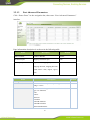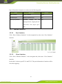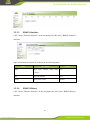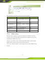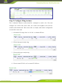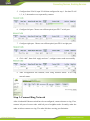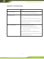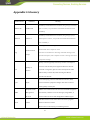
1
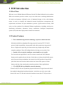
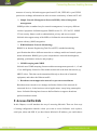
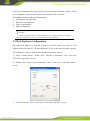
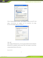
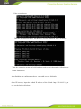
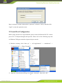
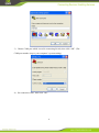
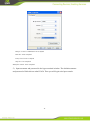
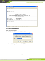
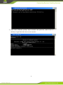
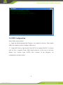
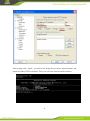
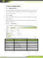
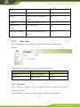
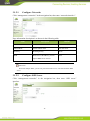
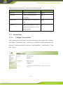
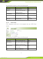
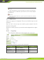
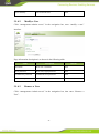
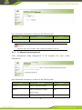
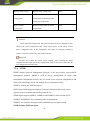
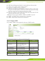
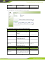
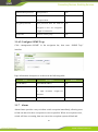
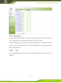
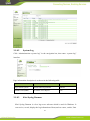
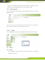
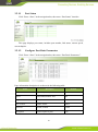
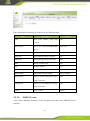
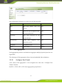
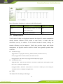
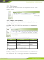
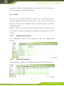
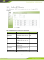
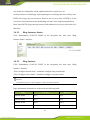
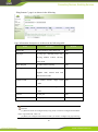
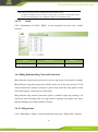
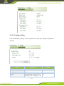
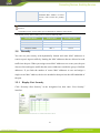
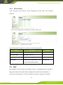
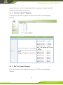
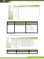
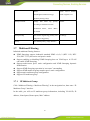
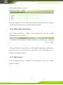
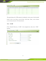
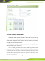
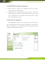
InSwitch Industrial Ethernet Switch ISM Series User’s Manual V4.3 InHand Networks Contents 1 ISM INTRODUCTION ................................................................................................................... 5 1.1 OVERVIEW ............................................................................................................................... 5 1.2 PRODUCT FEATURES ................................................................................................................. 5 2 ACCESS INSWITCH............................................................................................................................ 6 2.1 WEB EXPLORER CONFIGURATION............................................................................................. 7 2.2 SERIAL PORT CONFIGURATION ............................................................................................... 10 2.3 TELNET CONFIGURATION ........................................................................................................ 13 2.4 SSH CONFIGURATION ............................................................................................................. 15 3 WEB CONFIGURATION ................................................................................................................... 17 3.1 ADMINISTRATION ................................................................................................................... 17 3.1.1 System ............................................................................................................................... 17 3.1.2 Networks ........................................................................................................................... 18 3.1.3 System Time ...................................................................................................................... 20 3.1.4 Admin Access .................................................................................................................... 22 3.1.5 Configuration management ............................................................................................... 24 3.1.6 SNMP ................................................................................................................................ 25 3.1.7 Alarm ................................................................................................................................. 28 3.1.8 System Log ........................................................................................................................ 33 3.1.9 System Upgrade................................................................................................................. 35 3.1.10 3.2 Reboot ........................................................................................................................... 35 PORTS ..................................................................................................................................... 35 3.2.1 Ports ................................................................................................................................... 35 3.2.2 Ethernet Statistics .............................................................................................................. 39 3.2.3 Link Aggregation ............................................................................................................... 43 3.3 VIRTUAL LANS ...................................................................................................................... 44 3.3.1 VLAN Summary ............................................................................................................... 45 3.3.2 Configure VLAN Parameters ............................................................................................ 45 3.4 3.4.1 REDUNDANCY ........................................................................................................................ 45 RSTP ............................................................................................................................. 46 2 3.4.2 G.8032v2 ERPS .................................................................................................................... 48 3.4.3 iRing Ethernet Ring Network Protection .............................................................................. 51 3.5 SECURITY ............................................................................................................................... 53 3.5.1 Display Port Security ......................................................................................................... 53 3.5.2 Port Security ...................................................................................................................... 54 3.6 QOS ........................................................................................................................................ 54 3.6.1 Priority to Queue Mapping ................................................................................................ 55 3.6.2 DSCP to Queue Mapping .................................................................................................. 55 3.6.3 Port QoS ............................................................................................................................ 56 3.7 MULTICAST FILTERING ........................................................................................................... 57 3.7.1 IP Multicast Group ............................................................................................................ 57 3.7.2 Multicast Group Summary ................................................................................................ 58 3.7.3 IGMP Parameters............................................................................................................... 58 3.7.4 Configure Static Multicast Groups .................................................................................... 59 3.8 ....................................................................................................................................................... 60 3.8.1 Configure Static MAC ....................................................................................................... 60 3.8.2 Configure Dynamic MAC ................................................................................................. 61 3.9 NETWORK DISCOVERY ........................................................................................................... 61 3.9.1 LLDP Global Remote Statistics ............................................................................................ 61 3.9.2 LLDP Neighbor Information ................................................................................................. 62 3.9.3 LLDP Statistics ..................................................................................................................... 62 3.9.4 LLDP .................................................................................................................................. 63 3.10 DHCP BATCH CONFIGURATION................................................................................................... 64 3.10.1 DHCP Batch Configuration Preparation ............................................................................. 65 3.10.2 Parameters Configuration .................................................................................................... 65 3.11 USB CONFIGURATION AUTO- BACKUP AND RESTORE BY USB DISC ............................................ 67 APPENDIX 1 INTRODUCTION TO CLI COMMAND ...................................................................... 68 1 HELP .............................................................................................................................................. 68 2 USER MODE............................................................................................................................ 68 3 PRIVILEGED MODE ................................................................................................................. 69 3 4 CONFIGURE MODE.................................................................................................................. 70 5 PORT MODE............................................................................................................................. 71 6 VLAN MODE ......................................................................................................................... 72 7 RING INSTANCE CONFIGURATION MODE ................................................................................ 73 APPENDIX 2 RING NETWORK CONFIGURATION EXAMPLE ..................................................... 75 STEP 1: CONFIGURE DATA PATH .......................................................................................................... 75 STEP 2: CONFIGURE RING INSTANCE ................................................................................................... 76 STEP 3: CONNECT RING NETWORK ..................................................................................................... 77 APPENDIX 4 GLOSSARY....................................................................................................................... 79 SUPPORT............................................................................................................................................... 81 4 1 ISM Introduction 1.1 OverView Welcome to use InHand Industrial Ethernet Switch (For Short InSwitch) series product. ISM series switches provide a robust, easy to use and secure switching infrastructure for harsh environments. InSwitch series of industrial design, in line with industry norms; its tools to simplify the industrial network deployment, management and replacement; and based on open standards to provide a good network security. ISM series are idea productsl for industrial Ethernet applications, including wind power, distribution automation, substation, factory automation, intelligent transportation systems (ITS) and other deployments in harsh environments.. 1.2 Product Features Fast redundant ring network technology to protect critical network: InSwitches build fast redundant fiber ring network, based on ITU-T G.8032 protocol, high compatibility, interoperable with other proprietary ring protocol device. Support the single ring, the intersection ring, tangent ring and other complex topologies. Fast self-healing function, the ring recovery time<5ms Quality of Service(QoS), intelligent control multi-service traffic For some network applications, such as real-time control and VoIP, Ethernet frames need to predict the arrival time. Switch due to its frame-based buffer queue and a first-processing mechanism, the network load will produce a larger delay. QoS allows the time-sensitive data raised to the front of the queue to reduce latency and jitter, thus ensuring the normal operation of these applications. VLAN(IEEE 802.1q) Simplifies network planning Virtual LAN(VLAN) can separated a physical network to a logical network which has multiple independent broadcast domains. As the host can only access other hosts in the same VLAN and isolate the broadcast storm, thus VLAN provides a 5 measure of security. InSwitch support port-based VLAN, IEEE 802.1q and GVRP protocol to exchange information in order to ensure consistency of network VLAN. Simple Network Management Protocol(SNMP), allowed integrated management SNMP provides a standard way for network management, it can query different vendors’ equipment. InSwitch supports SNMP version V1, V2C and V3. SNMP V3 has security features such as authentication, privacy and access control. InSwitch also support many of the MIB, to facilitate the network management system with any (NMS) integration. RMON(Remote Network Monitoring) RMON is an Internet Engineering Task Force(IETF) standard monitoring specification that allows different networks to exchange media and control system status information. RMON gives you a comprehensive network fault diagnosis, planning, performance analysis, and prophecy. IGMP Snooping and GMRP InSwitch uses IGMP snooping (Internet multicast management protocol v1, v2 and v3) to intelligently forward or filter multicast network in the host data stream (eg MPEG video). This data can be transmitted directly to the needs of terminal equipment, and reduce the Ethernet traffic. Broadcast storm suppression network to prevent storm disaster Broadcast storm caused severe damage and lead to failure of the network all connected devices. In the business-critical applications, it may bring catastrophic losses. InSwitch filtering based on user-defined limits to suppress broadcast packets broadcast storms. 2 Access InSwitch In this Chapter, we will introduce the way of accessing InSwitch. There are four ways of setting configuration interface when you want to access InSwitch: web explorer, serial port, telnet and SSH. If you don’t know InSwitch’s IP address, you could choose 6 serial port configuration by using serial port line to connect InSwitch and PC’s COM port. In addition, telnet and web explorer are based on LAN or Internet. This chapter mainly includes the flowing parts: Web Explore Configuration Serial Port Configuration Telnet Configuration SSH Configuration Attention InSwitch support Web, serial, telnet and SSH, but we suggest you not to use multiple kinds of connection ways, thus you can effectively configure Inswitch . 2.1 Web Explorer Configuration The default IP address of InSwitch is http://192.168.2.2. Please set your PC’s IP address and ensure that PC’s IP and InSwitch’s IP are in the same network segment. The settings are as below (Based on the Windows operation system): 1) Open “Control Panel”, double click “Network Connections” icon, and enter “Network Connections” Screen. 2) Double click “Local Area Connection”, enter “Local Area Connection Status” screen: 3) Click “Properties”, enter “Local Area Connection Properties” screen: 7 Choose “Internet Protocol (TCP/IP)”, click “properties” button, set your PC in the subnet: 192.168.2.0/24, for example, set IP: 192.168.2.10, Net Mask: 255.255.255.0, Default Gateway: 192.168.2.2 Click “OK”. After configure TCP/IP protocols, you can use ping command to check whether the link between PC and Router is built correctly. There is an example to execute Ping command under Windows XP as below: Ping 192.168.2.1 8 If the screen shows: Then the link between the PC and Router is correct connected. Else if it shows: Then the connection seems not build, and you need to check thoroughly following the former instructions. After finishing the configuration above, you could set your InSwitch: Open IE browser, input the default IP address of the Switch: http://192.168.2.2, you can see the login web below: 9 Input “username”(default: adm) and the “password” (default: 123456), and then click “login” to enter the operation screen. 2.2 Serial Port Configuration Before using Serial Port to login InSwitch, please connect InSwitch’s RS-232 console port to PC’s COM port through serial port line. Please refer to the following steps and set Windows XP hyper terminal to login serial port console. 1) Windows desktop, click “Start up” -> “All Applications” -> “Attachment” -> “Communication” -> “Hyper Terminal”. 2) Input the connection describing, for example “InSwitch”, then click “OK”. 10 3) Choose COM port which is used in connecting Switch, then click “OK”. (The COM port number is up to your computer’s system setting.) 4) Set connection value, then click “OK”. 11 Bits per second: 115200 baud rate as default Data bit: 8 bits as default Parity check: none as default Stop bit: 1 bit as default Data flow control: none as default 5) Input username and password in the hyper terminal window. The default username and password of InSwitch are adm/123456. Then you will login serial port console. 12 2.3 Telnet Configuration Please follow steps as below: 1) Click “Start” -> “Run”, then input InSwitch IP address that you want to connect. You could also input telnet command in MS-DOS. 13 2) After enter command prompt, input username and password (adm/123456 as default) to login InSwitch telnet console interface. 14 2.4 SSH Configuration Please follow steps as below: 1) Login the Switch through Web Explorer, for example IE browser. Then enable SSH server function (refer to configure SSH server). 2) Using SSH Client to login Switch. Take PuTTY as example (PuTTY is a remote tools for free, it supports Telnet, SSH, rlogin protocols, in this case we will take Release 0.61 version). Open PuTTY, click “Session” in the categories, set configurations as picture below. 15 After setting, click “Open”, you will see the dialog box as below, input username and password (adm/123456 as default). Then, you will enter Switch console interface. 16 3 Web Configuration 3.1 Administration This chapter introduce system management, Administration settings include the 10 settings: system, networks, system time, admin access, config management, SNMP, alarm, log, upgrade, reboot。 3.1.1 System In the “System Status” web, you can check system’s basic information and running status information. In the “Basic Settings” web, you can set system’s basic configuration, including system language and host name.。 3.1.1.1 System Staus Click “configuration->system” in the navigation bar, enter “system status” web. Page information description is as shown in the following table. Parameters Name Description Default Name Switch host name none Model Switch model none Serial NO. Switch serial number none MAC address Switch MAC address() none Current version Switch firmware number none Current Bootloader Switch bootloader version number none 17 version Switch time Switch system time none Host time Visit host system time through web none interface Start time Running time from start to current none CPU load (1/5/15 CPU average load none Switch gross memory and remaining none minutes) Memory gross/remaining memory 3.1.1.2 Basic Setup Click “management-> system” in the navigation bar, then enter “Basic Setup” interface. Page information description is as shown in the following table. Name Description Default language Switch system language English Switch Name Switch host name InSwitch 3.1.2 Networks In the “Networks” interfaces, you can configure switch’s IP address and gateway, configure DNS server. In the “SSH server” interfaces, you can configure SSH server’s parameters。 18 3.1.2.1 Configure Networks Click “management->networks” in the navigation bar, then enter “networks interface”. Page information description is as shown in the following table. Name Description Default IP address Switch IP address 192.168.2.2 Subnet Mask Switch subnet mask 255.255.255.0 Gateway Default gateway None DNS DNS server’s IP address, you can none input 6 DNS server at most Instruction When fill multiple DNS, system will poll all the DNS server, until find available DNS server. 3.1.2.2 Configure SSH Server Click “management->networks” in the navigation bar, then enter “SSH server” interface. 19 Page information description is as shown in the following table. Name Description Default SSH status Enable or disable SSH server Disable Code mode Set PKI encryption mode(only RSA support RSA) Length o f key Set length of key, it could be 512 or None 1024 overtime SSH overtime, SSH server will be 120 disconnected when the server client has no operation. 3.1.3 System Time 3.1.3.1 Configure System Time Click “management->system time” in the navigation bar, enter “system time” interface. Then button “synchronous time ” will help user synchronize switch system time with host time. Configure parameter in the box “Year/Month/Date”, “Hour:Min:Sec”. Then click “Apply”. 20 Page information description is as shown in the following table. Name Description Default Switch time Switch system time none Host time Visit switch’s host system time none through web interface Year/Month/Day Year, Month, Day part of time Current year, month, day Hour:Minute:Second Hour, Minute, second part of time Current hour, minute, second Time zone System time zone 3.1.3.2 UTC+08:00 SNTP Client Click “management->system time” in the navigation, then enter “SNTP Client” interface. Page information description is as shown in the following table. Name Description Default SNTP Client Enable or disable SNTP Client disable Update Interval The interval between switch and 3600 SNTP Server synchronous time SNTP Servers list SNTP Server list, you can input 10 none server at most port The port of SNTP Server 21 123 Attention Before setting SNTP Server, please ensure SNTP server could be accessed. Especially, when SNTP server’s IP is domain name, please ensure that you have already configured correct DNS server. Instruction When setting multiple SNTP server, system will poll all the SNTP server, until find available SNTP server. 3.1.4 Admin Access Admin access supply user’s management. The user was divided into super user and normal user. Super user: there is only one super user created by system, username is adm. No limitation in visiting switch Normal user: created by super user, you can check switch configuration but no right to change. 3.1.4.1 Create User Click “management->admin access” in the navigation, enter “create a user”. Page information description is as shown in the following table. Name Description Default Username New user’s username none New password New user;s login password none Confirm new password Confirm the new password none 22 User summary 3.1.4.2 List of current users none Modify a User Click “management->admin access” in the navigation bar, enter “modify a user” interface. Page information description is as shown in the following table. Name Description Default Username New user’s username none New password New user;s login password none Confirm new password Confirm the new password none User summary List of current users none 3.1.4.3 Remove a User Click “management->Admin access” in the navigation bar, then enter “Remove a User”. 23 Page information description is as shown in the following table. Name User summary Description List current system users Default none Instruction Attention: super user’s username “adm” could not be modified or removed. 3.1.5 Configuration management Click “management->config management” in the navigation bar, enter “config management”. Page information description is as shown in the following table. Name Description Default Browser Choose config files from PC none Import Import config files to switch’s none startup-config Backup running-config Backup running-config to PC 24 none Backup startup-config Backup startup-config to PC none Auto save after modify the Decide whether or not to save enable configuration configuration automatically after modifying configuration. Restore default Restore Startup-config to default configuration configuration none Attention When import the configuration, the system will filter incorrect configuration files, and save the correct configuration files, when system restarts, it will orderly execute theses configuration files. If the configuration files didn’t be arranged according to effective order, the system won’t enter the desired state. Instruction In order not to affect the current system running , after executing the import configuration and restore the factory configuration, need to reboot the switch, then the new configuration will take effect 3.1.6 SNMP SNMP, Simple Network Management Protocol, is the most widely used network management protocol. SNMP is used in device management, to ensure that management information between any two points in the network transportation and make network manager check and manage device information easily. SNMP is divided into NMS and Agent NMS (Network Management Station) is running client procedure work station. Agent is a server software that running in the device. SNMP Agent support SNMPv1, SNMPv2c and SNMPv3 in the current device. SNMPv1 and SNMPv2 use community name to authenticate. SNMPv3 use username and password to authentication encryption mode. SNMP includes NMS and Agent: 25 NMS (Network Management Station) is a station which runs client procedure. Agent is service software which is running in device. The purpose of NMS and Agent is as followed: NMS can send getRequest, getNextRequest, setRequest packets to Agent, when the Agent receive these packets, it will execute read or write operations according to the type of packet and create Response packet back to NMS. When device happens to status change (for example port plug), Agent will send Trap packet and report all the events to NMS. SNMP agent of device supports SNMPv1, SNMPv2 and SNMPv3 at present. SNMPv1 and SNMPv2 adopt community name to authenticate. SNMPv3 adopt username and password to authenticate. 3.1.6.1 Configure SNMP Click “manage->SNMP” in the navigation bar, then enter “SNMP” interface. Page information description is as shown in the following table. Name Description Default Enable Enable or disable SNMP off SNMP Version Choose switch SNMP version, v2c support SNMP v1/v2/v3 Contact Information Input contact information Beijing_Inhand_Network Location Information Input location information Beijing_China Name Group name Description Enable or disable SNMP 26 Default Public and private Access authority Choose access authority ro MIB view Choose MIB view Default view After choosing SNMPv3, you need to configure users and user group: Page information description is as shown in the following table. Name Group name Description Input group name, Default length:1-32 none character Security level Choose security level No Auth/No private Read-only view Choose SNMP read-only view. Only Default view support default view now. Read-write view Choose SNMP write-only view. Only Default view support default view now. Inform view Choose SNMP Inform view. Only Default view support default view now. Name Description Default username Input username, length:1-32 character none authentication Choose authentication mode. Support none MD5 and SHA authentication mode. 27 Authentication password Input password Encryption Whether or none not to use DES DES Input password when the mode of none encryption mode Encryption password encryption is not “no encryption”. Length: 8-32 character Group name Add user to their group. none 3.1.6.2 Configure SNMP Trap Click “management->SNMP” in the navigation bar, then enter “SNMP Trap” interface. Page information description is as shown in the following table. Name Description Default Host IP address Input NMS IP address none Security Name For v1 or v2, input group name; For none v3, input username. Length:1-32 characters. UDP Port Input UDP port 162 3.1.7 Alarm Alarm feature provides a way to inform switch exception immediately, allowing users to find out and solve these exceptions as soon as possible. When an exception occurs, switch will issue a warning, then user can select exceptions system-defined and 28 choose the appropriate notice way to inform what happened. All alarms will be recorded in the alert log for users. According to the type of alarm, it can be divided system alarm and port alarm. System Alarm: It produces because of system or environment happened to some exception, divided into temperature, hot start, cold start, power failure, power recovery, insufficient memory. Port Alarm: It produces because of the network interface is up or down, divided into LINK-UP, LINK-DOWN. Alarm status divided into “raise”, “confirm”, “all”.The state of "raise" that means the alarms hadn’t been confirmed, if user cann’t resolve these alarms temporarily, he can set them to “confirm”state. The state of “all” means all the alarms Alarm level can be divided: EMERG:Device occurs some faults, it could lead to the system restart. CRIT:Device occurs some faults which are unrecoverable. WARN:Device occurs some faults which could affect system function. NOTICE:Device occurs some faults which could affect system properties. INFO:Device occurs some normal events. On the “Alarm Status” page, you can view all the alarms since system was power on. On the “Alarm Input” page, you can define alarm types which you concern. On the “Alarm Output” page, you can set the way of alarm notice, including relay and Email, log record is a default output way. On the “Alarm Map” page, you can map the alarm type which you concern to one or more alarm notice way. 3.1.7.1 Alarm Status Click on Administrator → Alarm→ Alarm Status, as the following shown: 29 Page information description is as shown in the following table. Name Description Default ID Generated by system none Status Current alarm status none Type Current alarm type none Level Current alarm level none date The time of generated alarm none System Time The time from startup to alarm none Content Description of alarm none 3.1.7.2 Alarm Input Click “Administrator → Alarm→ Alarm Input” in the navigation bar, then enter “Alarm Input”. 30 Page information description is as shown in the following table. Name Description Default Temperature On/Off Temperature exceeding alarm Off、 Upper Limit Temperature upper limit none Lower Limit Temperature lower limit none Warm Start On/Off warm start alarm on Cold Start On/Off cold start alarm on Power Down On/Off power down alarm on Power Up On/Off power up alarm on Memory Low On/Off memory low alarm on Link-up On/Off link-up alarm off Link-down On/Off link-down alarm on 3.1.7.3 Alarm Output Click “Administration->Alarm” in the navigation bar, then enter “alarm output” 31 Page information description is as shown in the following table. Name Description Default Enable Relay Alarm Enable/disable relay alarm disable Enable Email Alarm Enable/disable Email alarm disable Mail Server IP/Name Set mail server IP address none Mail Server Port Set mail server port 25 Account Name Set email address which system sent none alarm Email Account Password Set email password which system none sent alarm Email encryption Set encryption mode none Attention: After setting Email parameter, you should click “sent test mail” to sent test Email, to ensure that configuration is correct. 3.1.7.4 Alarm Map Click “Administration->alarm” in the navigation bar, then enter “alarm map” interface. 32 3.1.8 System Log Through “System log” interface, you can see important log since the start of switch. It easy to understand system status and will help solve problem in time. Through “System log” interface, you can set up remote log server, switch will take all system log files to upload remote server, which requires remote log software (such Kiwi Syslog Daemon). 3.1.8.1 Log Click “Administration->System log” in the navigation bar, then enter “system log” interface. 33 3.1.8.2 System Log Click “Administration->system log” in the navigation bar, then enter “system log” interface. Page information description is as shown in the following table. Name Description Default Log to remote system On/Off remote log function disabled IP Address/Port(UDP) Set remote server IP/port none 3.1.8.3 Kiwi Syslog Daemon Kiwi Syslog Daemon is a free log server software which is used for Windows. It can receive, record, display the log information of host(such as router, switch, Unix 34 host). After download and install Kiwi Syslog Daemon, configure necessary parameters on the configuration page of File->Setup->Input->UDP. 3.1.9 System Upgrade Click “Administration->system upgrade” in the navigation bar, then enter “system upgrade” interface. Click on “browser” button and select upgrade file, then click “upgrade” start to upgrade. The process will be lasted around 1 minute, after finishing, reboot switch. 3.1.10 Reboot Click “Administration->reboot” in the navigation bar, then enter “reboot” interface. 3.2 Ports 3.2.1 Ports Port configuration incudes port status, port basic parameters, port advanced parameters, port mirror. 35 3.2.1.1 Port Status Click “Ports->Ports” in the navigation bar, then enter “Port Status” interface. This page displays port status, includes port number, link status, current speed, current duplex. 3.2.1.2 Configure Port Basic Parameters Click “Ports->Ports” in the navigation bar, then enter “Port Basic Parameters”. Page information description is as shown in the following table. Name Description Default Admin Status Up(enable), Down(disable) up Speed 10M,100M,1000M or Auto auto Duplex Half, full or auto auto Flow Control Enable, disable disable Protected Normal, isolated normal Description The description of ports none 36 3.2.1.3 Port Advanced Parameters Click “Ports->Ports” in the navigation bar, then enter “Port Advanced Parameters” interface. Page information description is as shown in the following table. Name Description Default Enable monitor Enable or Disable Disable Destination port Mapping destination port none Source port parameter Appointed mapping port and none mapping direction, mapping direction could choose: none, ingress, egress, both Name Description Default Leaning Status Enable,Disable Enable The MAX Number The max number of dynamicaly learning MAC address. Range <1-255> none Broadcast Control That means which types broadcast will be limited. The type is as followed: none unicast multicast broadcast unicast& multicast unicast& broadcast multicast& broadcast none 37 all Broadcast rate(kbps) Desigate broadcast flow rate limit, range is 64-1000000 none Infow rate(kbps) Infow rate limit, range<64-1000000> none Excessive treament When inflow rate over the limit, the treatment can be: Drop, Flow-control, drop Outflow rate (kbps) Outflow limit,range<64-1000000> none Block unknown packets Blocking unknown packets. The flowing type can be choosed: none, unicast, multicast, both(unicast or multicast) Drop packet type Drop the received packets,the flowing packet type can be choosed none, tagged, untagged none VLAN transparent transmission In normal case, if the vlan id which port belongs to is not same with the vlan id of received packets carry. The packet will be droped, but if enable the vlan transparent trasnmissoin, the packet won’t be droped. Disable 3.2.1.4 Configure Port Mirrioring Click “Ports->Ports” in the navigation bar, then enter “configure port mirroring” interface. The flow of ingress from source port FE1/2 and the flow of egress from source port FE1/3 was mapped to destination port FE1/1. 38 Page information description is as shown in the following table. Name Description Default Enable monitor Enable or Disable Disable Destination port Mapping destination port none Source port parameter Appointed mapping port and none mapping direction, mapping direction could choose: none, ingress, egress, both 3.2.2 Ethernet Statistics 3.2.2.1 Port Statistics Click “Ports->Ethernet Statistics” in the navigation bar, then enter “Port Statistics” interface. 3.2.2.2 Clear Statistics Click “Ports->Ethernet Statistics” in the navigation bar, then enter “Clear Statistics” interface. In the table, it chooses port FE1/1 and FE1/2. The port information of statistics will be clear after applying. 39 3.2.2.3 RMON Statistics Click “Ports->Ethernet Statistics” in the navigation bar, then enter “RMON Statistics” interface. Page information description is as shown in the following table. Name Index Description Input index number, range from Default none 1-65534 Port Input port number FE1/1 Owner Input owner’s name Monitor 3.2.2.4 RMON History Click “Ports->Ethernet Statistics” in the navigation bar, then enter “RMON History” interface. 40 Page information description is as shown in the following table. Name Index Description Default Input index number, range from None 1-65535 Port Choose port Requested Buckets Management FE1/1 station expected None sampling gross Granted Buckets Device saved sampling gross None Interval Sampling time(second) None Owner Owner’s name Monitor 3.2.2.5 RMON Alarms When the alarm is triggered, if you need to manage device(NMS) to send Trap messages, please ensure that SNMP function has been configured correctly before configuration of RMON alarm feature. Statistics Section alarm variable is defined in the MIB variable, it must configure RMON Ethernet statistics under monitored Ethernet interface. Click “Ports->Ethernet Statistics” in the navigation bar, then enter “RMON Alarm” interface. 41 Page information description is as shown in the following table. Name Index Description Input index number, range from Default None 1-65535 Alarm Object Choose the monitored RMON-MIB DropEvents object Statistics Index Choose statistics index None Rising Thr Input sampling statistics rising thr None Falling Thr Input sampling statistics falling thr None Value Monitor variable value None Type Absolute or Delta delta Interval Sampling time interval None Startup Alarm Only support rising or falling Rising or falling Rising Event When it exceeds rising limit, trigger None rising event index Falling Event When it exceeds falling limit, trigger None falling event index Owner 3.2.2.6 Owner’s name Monitor RMON Events Click “Ports->Ethernet Statistics” in the navigation bar, then enter “RMON Events” interface. 42 Page information description is as shown in the following table. Name Index Description Default Input index number, range from None 1-65535 Type Choose the type of triggered events: None log, trap, log-trap, none Trap’s group name(only for type Community None log-trap and trap) Last Time Sent Record latest triggered event, None generated by system Description Description of event None Owner Owner’s name Moniter 3.2.3 Link Aggregation Link aggregation provides a mechanism to aggregate multiple physical ports into one logical link. The advantage of link aggregation: linear increase bandwidth; link redundancy.。 3.2.3.1 Configure Port Trunk Click “Ports->Link aggregation” in the navigation bar, then enter “Configure Port Trunks” interface. Put FE1/1, FE1/2, FE1/3, FE1/4 into aggregation group Trunk 1. 43 Page information description is as shown in the following table. Name Policy Description Load balancing strategy, you could Default sada choose: sada or hash. Trunk port 3.3 Appointed trunk member None Virtual LANs VLAN can be flexible on the physical network into logical. It cannot communicate directly between different VLAN, which to some extent, to ensure data and information security. In addition, VLAN isolated broadcast domain, making the network efficiency can be improved. VLAN also provides simple and flexible management, the physical network could be divided into segments separated from each other. VLAN Frame Type Tagged Frame: Carrying the VLAN tag . TPID is 0x8100, the VID of TCI is 0; Priority Tagged Frame: TPID is 0x8100, the VID of TCI is 0. Untagged Frame: The frame except Tagged frame and priority tagged. VLAN Member Type Tagged Member,When the VLAN frame is sent from a member port, will bring the VLAN label, that is sending the Tagged frame. Untagged Member, When the VLAN frame is sent form a member port, won’t bring the VLAN label, that is sending the untagged frame. PVID The default VLAN which port belong to. 44 3.3.1 VLAN Summary Click “Virtual LANs->Static Virtual LANs” in the navigation bar, then enter “VLAN Summary” interface. 3.3.2 Configure VLAN Parameters Click “Virtual LANs->Static Virtual LANs” in the navigation bar, then enter “Configure VLAN Parameters” interface. For example, VLAN ID is 2, name is test, FE1/1 and FE1/2 is untagged member, FE1/3 is tagged member. Page information description is as shown in the following table. Name Description Default VLAN ID VLAN ID, range from 1-4094 1 Priority VLAN Priority, range from 0-7 0 Name VLAN name VLAN0001 Port member Choose port member role, you could none choose: none, tagged, untagged. 3.4 Redundancy Redundancy, which is a part of the network circuit that has some malfunctions will have a backup path. This is the most basic requirements of industrial automation 45 applications. IEEE 802.1D Rapid Spanning Tree Protocol and ITU-T G8032 ring protection technology are the latest technology. 3.4.1 RSTP The main role of the RSTP includes two aspects: first, by blocking the link to eliminate redundant network paths that may exist in loop; second, the current active path fails, the link activate redundant backup and restore network connectivity, enabling backup links. RSTP, by sending a special packet protocol between switch each other, process received packet according to spanning tree algorithm, then determine the network topology. 3.4.1.1 Bridge RSTP Statistics Click “Redundancy-> RSTP” in the navigation bar, then enter “Bridge RSTP Statistics”. 3.4.1.2 Port RSTP Statistics Click “Redundancy-> RSTP” in the navigation bar, then enter “Port RSTP Statistics”. 46 3.4.1.3 Configure RSTP Parameters Click “Redundancy RSTP” in the navigation bar, then enter “Configure RSTP Parameters”. Page information description is as shown in the following table. Name Description Default Enable RSTP Enable or disable RSTP enable Bridge Priority Set RSTP bridge priority, range from 32768 0-61440 Hello Time Set RSTP timing time interval when 2 sent BPDU packet, range from 1-10 seconds. Max Age Set RSTP BPDU max life time, range 20 from 6-40 seconds Forward Delay Set RSTP spanning tree delay, range 15 from 4-30 seconds. Transmit Hold Count Set transmit hold count per second 47 6 Name Description Default Enable RSTP Enable or disable RSTP Disable Port Priority Set RSTP port priority, range from 128 0-240 Spanning-tree Cost Set RSTP port route, range from Auto 1-200000000 or auto Edge Port Set value of edge port, yes means No force configured edge port, no means auto Point-to-Point Set connection point-to-point. Yes value of means force Auto configured point-to-point port; no means force configured port shared link. Attention Hello time,the max age time, and forward delay, the three paremeters have their own value range, and they need to meet the following relationship: 2*(Hello Time + 1.0 seconds) <= Max-Age Time <= 2*(Forward-Delay – 1.0seconds) The three parameters must meet this requirement, otherwise may lead to topology is instable. 3.4.2 G.8032v2 ERPS Ring protection technology is an open protocol launched by ITU which is applied in the data link layer. It can prevent broadcast storms caused by data loops. When the loop-line link or equipment failed, it can switch to a backup link, to ensure than quick business recovery. Rapid Ring Protection Protocol is the use of ring fault recovery within a dedicated control network VLAN passing ring network control message. Also, it combined with the topological characteristics of the ring itself, if malfunction 48 was found out, backup link will be enabled and achieve rapid recovery. In the protection of technology, rapid spanning tree technology has been widely used. RSTP will occupy the port resources, however, the recovery time of RSTP is in the second level and cannot meet the demanding real-time in the industrial applications. More faster RSTP, ring protection protocol link malfunction recovery time can be less than 5ms. 3.4.2.1 Ring Instances Status Click “Redundancy->G.8032v2 ERPS” in the navigation bar, then enter “Ring Instance Status” interface. 3.4.2.2 Ring Instance Click “Redundancy->G.8032v2 ERPS” in the navigation bar, then enter “Ring Instance” interface. “Fast Configure Normal Node”, automatic configure ring normal node “Fast Configure Owner Node”, automatic configure ring owner node Attention The default ring port in “Fast Configure” is based on InSwitch model。 Page information description is as shown in the following table. Model Left Port Right Port InSwitch 2008D FE1/7 FE1/8 InSwitch 2009D FE1/7 FE1/8 InSwitch 3010D GX1/1 GX1/2 InSwitch 3028U GE1/1 GE1/2 49 “Ring Instance” page is as shown in the following Page information description is as shown in the following table. Name Description Default Instance ID Set ring instance, range from 1-10 None Ring Type Set ring type, including major ring, None sub-ring without V-chan, sub-ring with V-chan. Major Ring ID Set when choose sub-ring. None Node Type Set node type, including owner node, None neighbor node, normal node and interconnection node. Control VLAN Set control VLAN, range from None 1-4094 Service VLAN Set service VLAN, range from None 1-4094 Left Port Set left port None Right Port Set right port None Attention [1] When the node was configured major ring node, it cannot be configured subordinate major ring instance ID, value is 0. [2] When you configure interconnection node, you need to configure ring type sub-ring 50 node. Major ring node cannot be configured as interconnection node. [3] Before configuring the data VLAN of ring instance, you need to created new VLAN. [4] You need add ring port into configured control VLAN and data VLAN 3.4.2.3 OAM Click “Redundancy->G.8032v2 ERPS” in the navigation bar, then enter “OAM” interface. Name OAM Status Description Set OAM Status. Default Disable 3.4.3 iRing Ethernet Ring Network Protection iRing Ethernet ring protection protocol is private ring protocol developed by inhand. IRing Ethernet ring protection protocol define node role on the loop, and use VLAN control transmission protocol message to protect loop, make the loop quickly switch when fauls happen, switch time less than 50ms. iRing Ethernet ring network protection system is suitable single ring topology, can effectively deal with single fault of a ring network, topology convergence rate quick, and has nothing to do with the number of nodes. 3.4.3.1 iRing Status Click “Redundancy->iRing” in the navigation bar, then enter “iRing status” interface. 51 3.4.3.1 Configure iRing Click “Redundancy->iRing” in the navigation bar, then enter “iRing configuration” interface. Name Description Default Enable iRing whether to enable iRing protocol Primary Port designate the main prot FE1/7 Secondary Port designate the secondary prot FE1/8 Priority Switch differentiate the primary or secondary port according to the 100 52 priority.The port which have minimum MAC address or lowest priority will become the primary port Attention The default primary and secondary port are different for different switch model. The default primary and secondary port are shown as following table. 3.5 InSwitch Model Primary Port Secondary Port InSwitch 2008D FE 1/7 FE 1/8 InSwitch 2009D FE 1/7 FE 1/8 InSwitch 3010D GX1/1 GX1/2 InSwitch 3028U GE1/1 GE1/2 Security You can use port security with dynamically learned and static MAC addresses to restrict a port's ingress traffic by limiting the MAC addresses that are allowed to send traffic into the port. When you assign secure MAC addresses to a secure port, the port does not forward ingress traffic that has source addresses outside the group of defined addresses. If you limit the number of secure MAC addresses to one and assign a single secure MAC address, the device attached to that port has the full bandwidth of the port. 3.5.1 Display Port Security Click “Security->Port Security” in the navigation bar, then enter “Port Security” interface. 53 3.5.2 Port Security Click “Security->Port Security” in the navigation bar, then enter “Port Security” interface. You can click each port line to configure port security characteristic. Page information description is as shown in the following table. Name Description Default Enable Port Security Enable or disable Disable Max Secure MAC Max number can be set 1 VLAN ID VLAN ID of MAC address 1 Secure MAC Configured secure MAC address, form 0000.0000.0001 should be HHHH.HHHH.HHHH 3.6 QoS QoS (Quality of Service) that is the quality of service, can guarantee the reception of high priority data frame and accelerate high-priority data frame transmission, to ensure that critical business will not be impact by network congestion. InSwitch 54 support four service levels, according t data frame reception port, Tag priority and IP priority level to determine service level. 3.6.1 Priority to Queue Mapping Click “QoS->QoS” in the navigation bar, then enter “Priority to Queue Mapping” interface. Name Priority Queue Description Default IEEE Tag Priority None Service level,range<0-3>,The number is more greater, the sevice level is more higher Note:The range of rack switch<0-7> Default Mapping: Priority Level 0-1 --->Queue0 Priority Level 2-3 --->Queue1 Priority Level 4-5 --->Queue2 Priority Level 6-7 --->Queue3 Note:The default map of rack switch: Priority Level 0 --->Queue 0 Priority Level 1 --->Queue 1 Priority Level 2 --->Queue 2 Priority Level 3 --->Queue 3 Priority Level 4 --->Queue 4 Priority Level 5 --->Queue 5 Priority Level 6 --->Queue 6 Priority Level 7 --->Queue 7 3.6.2 DSCP to Queue Mapping Click “QoS->QoS” in the navigation bar, then enter “DSCP to Queue Mapping” interface. 55 Name Description Default DSCP IP priority, range from<0-63> None Queue Service level, range from<0-3>. Default mapping: Priority 0-15 Queue 0 Priority 16-31 Queue 1 Priority 32-47 Queue 2 Priority 48-63 Queue 3 3.6.3 Port QoS Click “QoS->QoS” in the navigation bar, then enter “Port QoS” interface. Name Policy Description Port sending queue policy, you could 56 Default Wrr choose: Queue 3:2:1:0 should Wrr(Weighted rotation strategy) match weight 8:4:2:1 Sp(Strict priority policy) Priority Override Change data frame tag priority Disable according to information below: Destination MAC, source MAC, VLAN ID Priority Remap Data frame original tag priority was No change mapped new tag priority. Priority 3.7 Port default priority, range from 0-7 0 Multicast Filtering InSwitch multicast filtering features: IGMP Snooping support industrial standard IGMP v1,v2,v3 (RFC 1112, RFC 2236, RFC 3376), has active and passive mode. Support enabling or disabling IGMP Snooping base on VLAN,up to 16 VLAN can enable IGMP Snooping. Support multi-router port’s static configuration and IGMP Snooping dynamic identification. Support IGMP Snooping operation in “no-router” surrounding Support IGMP multicast group member port’s static configuration Support static multicast group configuration Support 256 multicast group 3.7.1 IP Multicast Group Click “Multicast Filtering-> Multicast Filtering” in the navigation bar, then enter “IP Multicast Group” interface. In the table, you will see IP multicast group information, including VLAN ID, IP address, Joined ports, Router ports, MAC address. 57 3.7.2 Multicast Group Summary Click “Multicast Filtering-> Multicast Filtering” in the navigation bar, then enter “IP Multicast Group” interface. In the table, you will see multicast group summary of dynamic configuration, including VLAN ID, MAC address, static port. 3.7.3 IGMP Parameters Click “Multicast Filtering-> Multicast Filtering” in the navigation bar, then enter “IP Multicast Group” interface. 58 Name MAC address Description Input MAC address that match with Default None IGMP multicast group VLAN ID Choose multicast group VLAN None Port Choose IGMP multicast group’s static None member port 3.7.4 Configure Static Multicast Groups Click “Multicast Filtering-> Multicast Filtering” in the navigation bar, then enter “IP Multicast Group” interface. 59 Name MAC address Description Default Input MAC address that match with None IGMP multicast group VLAN ID Choose multicast group VLAN None Priority Choose priority of static multicast 7 group address lis Choose IGMP multicast group’s static Port None member port 3.8 MAC Address Tables MAC Address list features: Check the learning MAC address Delete unicast MAC table items Configure switch MAC address aged time Configure static unicast MAC address 3.8.1 Configure Static MAC Click “MAC Address Tables-> MAC Address Tables ” in the navigation bar, then enter “Configure Static MAC” interface. Name Description Default MAC address Input unicast MAC address None VLAN Input host belonged VLAN 1 Port Input port matched 60 with MAC None address Priority Input priority matched with MAC 0 address 3.8.2 Configure Dynamic MAC Click “MAC Address Tables-> MAC Address Tables ” in the navigation bar, then enter “Configure Dynamic MAC” interface. Name Description Remove dynamic MAC Choose removed dynamic address address Aged time Input MAC address aged time Default MAC None 300 3.9 Network Discovery Link Layer Discovery Protocol running on the data link layer. Through the LLDP, one device can obtain some information of other devices which connected with (such as the host name), even they are running different protocols on the network layer. 3.9.1 LLDP Global Remote Statistics Click “Network Discovery-> LLDP” in the navigation bar, then enter “LLDP 61 Global Remote Statistics” interface. This page displays the LLDP global remote statistics network discovery, including overtime frame, insert frame, discard frame,and delete frames. 3.9.2 LLDP Neighbor Information Click “Network Discovery-> LLDP” in the navigation bar, then enter “LLDP Neighbor Information” interface. This page displays the network discovery LLDP neighbor information, including port, classis ID, port ID, port description, system name, system description, type of equipment, management address. 3.9.3 LLDP Statistics Click “Network Discovery-> LLDP” in the navigation bar, then enter “LLDP Statistics” interface 62 This page displays the LLDP statistical, including the various ports of the discarded frames, receive error frame, received frame, send frame, frame, receive timeout receive frame and receive TLV frame discard 3.9.4 LLDP Click “Network Discovery-> LLDP” in the navigation bar, then enter “LLDP ” interface. 63 3.10 DHCP Batch Configuration Automatically batch configuring switches via DHCP and TFTP can save time and lower labor cost, making management and maintenance much easier. It also avoids manual configuration errors caused by improper operation, avoid repetitive work and ensure configuration consistency. DHCP refers to an IP address range controlled by server. It assigns IP address and Subnet Mask once the clients log on. TFTP is a simple file transfer protocol used to transfer files between remote server and local host. TFTP protocol is based on UDP protocol. TFTP transfer request is initiated by the client, when the TFTP client needs to download files from the server, the client sends a request packet to the TFTP server, and receives data from the server and sends acknowledgment. 64 3.10.1 DHCP Batch Configuration Preparation 1) Enable TFTP Server. Prepare switch configuration files and save effective configuration files under TFTP directory. 2) Enable DHCP Server. Configure DHCP parameters related to TFTP Server, sharing the IP address of TFTP Server where configuration files are saved and the name of configuration files (.cnf); DHCP Server assigns IP address,network mask,default gateway to switches. 3.10.2 Parameters Configuration Click “Administration> Networks” in the navigation bar, then enter “Networks” page. Click “DHCP Client” and “Enable Config via DHCP Server” as shown below, then click “Apply&Save” to save configuration; swithes will automatically acquire configuration files and upload to the system. 65 When DHCP client have been enabled, if you also enable “Enable Config via DHCP Server”, the DHCP client will reboot. When DHCP client haven’t been enabled, if you enable “Enable Config via DHCP Server”, DHCP client will be enabled automatically. After acquiring configuration files and uploading to switch, the switch will automatically reboot. After reboot, “Enable Config via DHCP Server” function will be disabled by default. When the function is enabled but the configuration is not acquired, if switch reboots(user reboot or caused by other reasons) the “Enable Config via DHCP Server” function is enabled by default. After the configuration is acquired, switch’s IP address, subnet mask, default gateway and DNS are still from DHCP Server, not from configuration files. Normally, it takes 40 seconds from enabling to configuration acquired(exclude switch reboot time). On switch WEB page, the description in the brackets following “Enable DHCP Configuration” shows the satus of configuration: 1) “Config is already acquired": Configuration has been successfully acquired from server. This case includes: (1) Acquiring configuration function is now “Enabled” and configuration acquired; (2) the function is now “Disabled”, but the configuration is acquired after last time’s “On”. 2) “Config is not acquired yet”: Acquiring configuration function has been enabled, but configuration is not acquired yet. 3) “Not enabled”: Acquiring configuration function is not enabled. Before acquiring configuration successfully, if this function or DHCP function is disabled, the status will be switched to “Not enabled”. After obtaining IP address and configuration file via DHCP, the IP related configuration parameters will be saved to configuration file, that means the switch’s static IP address is the IP address assigned by DHCP. So it’s necessary to modify the IP address pool of DHCP server after finish the deployment, in case to assign a same IP address to other device. 66 3.11 USB Configuration auto- Backup and Restore by USB Disc When the switch needs to be replaced due to failure, you can back up the configuration file from the faulty switch with a USB disk. USB disk can be used to backup and automatically synchronize the configuration file of the switch. When the system of the switch detects a USB disc inserted, if there is no configuration files inside in the USB disc, the current configuration file will be downloaded into the USB disk. Thereafter, when the configuration changes, the system will automatically synchronize the changes to the USB disc to keep the configuration file in the USB disk is always the latest. Highly suggest that each switch equipped with a USB disc, this can keep the real-time synchronizationWhen the equipment needs to be replaced due to failure, simply insert the USB disc form the faulty switch into the replaced switch, then reboot this switch by power on. In this process, when the configuration files in the USB disk detected by the replaced switch, the switch will automatically download this configuration file form the USB disc and restore, complete seamlessly replacement. 67 Appendix 1 Introduction to CLI Command 1 Help After entering CLI, input “help”, you can know more about help information user guide. ****************************************************************************** 11:06:35 InSwitch > help Input interrogation mark “?”, you can check help information at any point of command. If it does not match successfully, then the help list is empty. You must back to input content until system shows valid option after input “?”. System provides two kind of help style: 1. When you have prepared command parameter, please using entire help. For example, “show ?” Entire help will describe every potential parameter. 2. When you input a short parameter and want to get matching parameter list, please using part help. For example, “show pr?”. 11:06:35 InSwitch> **************************************************************************** 2 User Mode Login CLI means login user mode. Input “?”, it will show executable command. *************************************************************************** 11:08:44 InSwitch> command Description Enable Switch to privileged mode Exit Quit view/control Help Get help command Hostname Set hostname Language Set operation language Ping Ping detection Show Show running status Telnet Telnet login traceroute Router detection 11:08:44 InSwitch> *************************************************************************** 68 3 Privileged Mode With user mode, input “enable ”, you will enter privileged mode, input “?”, it will show the executable command. ******************************************************************************* 11:20:07 InSwitch>enable Please input password: 11:20:09 InSwitch# Executable command: command Description Configure Enter configure mode Copy Copy files Default Recover appointed parameter as default Disable Quit privileged mode Erase Clear files Exit Quit view/control Help Get help command Hostname Set hostname Language Set operation language No Cancel setting of appointed parameter Password Set password Ping Ping detection reboot Reboot system Show Show running status Telnet Telnet login traceroute Route detection Username Set username and password 11:20:10 InSwitch# *************************************************************************** 69 4 Configure Mode With privileged mode, input “configure terminal”, enter configure mode, then input “?”, it will show executable command. *************************************************************************** 11:21:10 InSwitch# configure terminal 11:21:11 InSwitch config# command Description Alarm Set warn Clear Clear information or configuration Clock Set system time Copy Copy files Crypto Set SSH parameter Default Recover appointed parameter as default Disable Quit privileged mode Email Set email parameter Erase Clear files Exit Quit view/control G8032 G8032 ring network protected protocol gmrp GMRP configuration help Get help command Hostname Set hostname Iec61850 IEC 61850 interface Enter port mode ip Overall IP configuration language Set operation language lacp LACP setting lldp LLDP protocol log Remote log server mac MAC address setting 70 monitor Port moniter no Cancel setting of appointed parameter password Set password ping Ping detection port-channel TRUNK setting qos QoS reboot Reboot system rmon Remote moniter relay Set relay parameter show Show running status snmp-server Modify SNMP parameter sntp-client Set network time server spanning-tree Spanning-tree protocol telnet telnet login traceroute Route detection temperature Set temperature for warning limitation username Set username and password vlan VLAN setting 11:21:14 InSwitch config# ******************************************************************************* 5 Port mode With privileged mode, input “interface fastehernet 1/1”, enter fastethernet 1/1 port mode, then input “?”, it will show executable command. ****************************************************************************** 11:23:02 InSwitch config# interface fastethernet 1/1 11:23:02 InSwitch-FE-1/1# 11:23:46 InSwitch-FE-1/1# Port configuration command: command block Description Block flow of port 71 cfm Link connection detect channel-group Ethernet connection pond setting default Recover appointed parameter as default description Add interface description discard Import frame discard duplex Setting duplex-mode exit Quit view/control Flow-control Flow control help Get help command lacp LACP port configuration learn MAC address learning lldp Setting LLDP no Cancel setting of appointed parameter Port-security Port security protected Set port protection qos QoS rate-limit Limit rate rmon Remote moniter show Show running status shutdown Port off spanning-tree Spanning-tree protocol speed Set port rate storm-control Control storm vlan-tunnel VLAN transparent transmission 11:23:47 InSwitch-FE-1/1# *************************************************************************** 6 VLAN Mode With privileged mode, input “VLAN 100”, enter VLAN mode, then input “?”, it will show executable command. ******************************************************************************* 72 11:25:05 InSwitch config# vlan 100 11:25:06 InSwitch-vlan-100# VLAN configuration command: command Description default Recover appointed parameter as default exit Quit view/control help Get help command Iec61850 IEC 61850 member Setting VLAN member name Add VLAN name no Cancel setting appointed parameter priority Setting VLAN priority show Show running status 11:26:59 InSwitch-vlan-100# ******************************************************************** 7 Ring Instance Configuration Mode With privileged mode, input “g8032 10”, enter ring instance configuration mode, then input “?”, it will show executable command. *************************************************************** 11:28:56 InSwitch config# 11:29:05 InSwitch config# g8032 10 G8032 Instance id is 10, is ok 11:29:05 InSwitch-InRing-10# Get help command You can input “?” to get help anytime during inputting command command Description control-vlan Set ring network control vlan default Recover appointed parameter as default enable G8032 instance exit Quit view/control help Get help command no Cancel setting appointed parameter 73 node-type Set node type port Set ring network port ring-type Set ring type show Show running status service-vlan Set ring netword data vlan 11:29:07 InSwitch-InRing-10# *************************************************************** Attention: After one ring instance worked, the instance is running, it cannot enter configuration mode. 74 Appendix 2 Ring Network Configuration Example First, there are two data path in the ring network, including the data path of transmitted ring control message and data path of transmitted business data. As a result, before configuring ring, you need to establish data path, that is configured VLAN. Then, there are three different roles of nodes in the ring, respectively owner node, neighbor nodes and normal nodes. Owner node: when the ring network link failure, open backup link in time and notify the other nodes; after a link back to normal in the ring network, please block backup link. Neighbor node: when the ring network link failure, open backup link in time; after the ring network link recovery, waiting for a confirmation sent by owner node that link is normal, then block backup link. Normal node: when the ring network link failure, notify other nodes. In the ring network, you must configure an owner node, however, neighbor node configuration is not required. Finally, after the end of each node configured, pay attention that the left port is backup link port as default for owner node and neighbor node, so you need to ring the two ports connected to the left. Take 4 ISM2009D industrial Ethernet switch as example. The configuration step as below: Step 1: Configure Data Path Click “Virtual LANs Static Virtual LAN ” in the navigation bar, then enter “VLAN configure” interface. In each switch, add tagged port FE1/7 and FE1/8 into VLAN 2,3,4,5, then click apply. 75 Step 2: Configure Ring instance The 4 industrial Ethernet switch should be configured as node’s role. You need configure one switch with owner node, one switch with neighbor node and two switches with normal node. Take owner node as example, other nodes’ configuration are same like owner node. 1. Set instance ID, range from 1 to 10. Set 1 as instance ID here. 2. Choose ring type as major ring. 3. Choose node type as major ring. 4. Choose control VLAN, set 2 as control VLAN here 76 5. Configure data VLAN, input VLAN that configured in step 1. Set data VLAN 1, 3, 4, 5, the number was separated by comma. 6. Configure left port. Choose one trillion optical port FE1/7 as left port. 7. Configure right port. Choose one trillion optical port FE1/8 as right port. 8. Click “add”, then click “apply and save”, configure owner node successfully. 9. After configuration was finished, click “Ring Instance Status” to see ring network status. Step 3: Connect Ring Network After 4 industrial Ethernet switch have been configured, connect them to a ring. First, connect left port of owner node with left port of neighbor node. Secondly, make the other switches connect to a ring. The other link have no ring port limitation. 77 Appendix 3 Troubleshooting FAQ Methods Power indicator doesn’t light (1) Please check the power line if connected correctly. (2) Please check the power line plug is plugged in tight, no loose Port indicator doesn’t light (1) Please check if the cable and switch port connect tightly, there are no loose (2) Two cables are respectively inserted into the two port of the switch, if the two indicators that two Ethernet prots corresponding to light, that means cable is normal; otherwise the cable may be a problem, please replace the cables and try again Can’t access to switch by WEB (1) Using the ping command to check network Ping 127.0.0.1 to check the TCP/IP if is installed Ping the defautlt IP address of switch, to check if the PC can communicate with switch. (2) Ensure the PC’s IP is in a same network segment with switch (3) check the Web browser is set up a proxy server or dial-up connection, if any, please cancel 78 Appendix 4 Glossary Abbreviations Full Name Meaning 100Mbit/s baseband Ethernet standard, using the type 5 twisted 100Base-TX 100Base-TX pair to connect, can provide the maximumtransmission rate of 100Mbit/s 100Mbit/s baseband Ethernet standard, using the type 3/4/5 10Base-T 10Base-T twisted pair to connect, can provide the maximumtransmission rate of 10Mbit/s The Ping command is a diagnostic tool used to test the machineand other computers on the Packet Internet Ping network can communicate. The Ping command message to the Grope specified computer, if the computerreceives a message will return a response message Quality of service (Quality of Service) is used as a technique to solve the network delay and congestion. When the network Quality of QoS overload or congestion, QoS can ensure the important traffic Service without delay or discarded, while ensuring the efficient operation of network. For standard plug connected with Ethernet switches, hubs, RJ-45 RJ-45 routers and other equipment. Straight cable and a crossover cable typically use this joint SNMP Simple Network SNMP is the communication rules between the NMS and agent in Management the network, it defines a series of messages, and grammar, is Protocol used to realize the access and management of NMS to agent A method used to access remote host’s interactive program Telnet Telnet based on characters. Telnet Allows users to remotely log on and manage device 79 Wide area network (Wide Area Network) is a data Wide Area WAN communication network covering the geographic range is Network relatively wide, such as the Internet LAN (Local Area Network) generally refers to the internal Local Area LAN network, such as the family network, small and medium-sized Network enterprise internal network etc. 80 Support In case you have problems with the installation and use, please address them to us by e-mail: [email protected]. InHand Networks Headquarters West Wing, 11th Floor, Qi Ming Mansion Wang Jing Science Park, Chao Yang District Beijing, 100102, China T:+86-10-6439-1099 F:+86-10-8417-0089 [email protected] US Office 7926 Jones Branch Dr. Suite 110 McLean, Virginia 22102 USA T: +1-703-348-2988 F:+1-703-348-2988 www.inhandnetworks.com 81