1
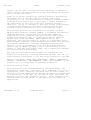
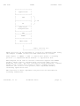
Network Working Group
Request for Comments: 2728
Category: Standards Track
R. Panabaker
Microsoft
S. Wegerif
Philips Semiconductors
D. Zigmond
WebTV Networks
November 1999
The Transmission of IP Over the Vertical Blanking Interval of a
Television Signal
Status of this Memo
This document specifies an Internet standards track protocol for the
Internet community, and requests discussion and suggestions for
improvements. Please refer to the current edition of the "Internet
Official Protocol Standards" (STD 1) for the standardization state
and status of this protocol. Distribution of this memo is unlimited.
Copyright Notice
Copyright (C) The Internet Society (1999).
All Rights Reserved.
1. Abstract
This document describes a method for broadcasting IP data in a
unidirectional manner using the vertical blanking interval of
television signals. It includes a description for compressing IP
headers on unidirectional networks, a framing protocol identical to
SLIP, a forward error correction scheme, and the NABTS byte
structures.
2. Introduction
This RFC proposes several protocols to be used in the transmission of
IP datagrams using the Vertical Blanking Interval (VBI) of a
television signal. The VBI is a non-viewable portion of the
television signal that can be used to provide point-to-multipoint IP
data services which will relieve congestion and traffic in the
traditional Internet access networks. Wherever possible these
protocols make use of existing RFC standards and non-standards.
Traditionally, point-to-point connections (TCP/IP) have been used
even for the transmission of broadcast type data. Distribution of
the same content--news feeds, stock quotes, newsgroups, weather
Panabaker, et al.
Standards Track
[Page 1]
RFC 2728
IPVBI
November 1999
reports, and the like--are typically sent repeatedly to individual
clients rather than being broadcast to the large number of users who
want to receive such data.
Today, IP is quickly becoming the preferred method of distributing
one-to-many data on intranets and the Internet. The coming
availability of low cost PC hardware for receiving television signals
accompanied by broadcast data streams makes a defined standard for
the transmission of data over traditional broadcast networks
imperative. A lack of standards in this area as well as the expense
of hardware has prevented traditional broadcast networks from
becoming effective deliverers of data to the home and office.
This document describes the transmission of IP using the North
American Basic Teletext Standard (NABTS), a recognized and industrysupported method of transporting data on the VBI. NABTS is
traditionally used on 525-line television systems such as NTSC.
Another byte structure, WST, is traditionally used on 625-line
systems such as PAL and SECAM. These generalizations have
exceptions, and countries should be treated on an individual basis.
These existing television system standards will enable the television
and Internet communities to provide inexpensive broadcast data
services. A set of existing protocols will be layered above the
specific FEC for NABTS including a serial stream framing protocol
similar to SLIP (RFC 1055 [Romkey 1988]) and a compression technique
for unidirectional UDP/IP headers.
The protocols described in this document are intended for the
unidirectional delivery of IP datagrams using the VBI. That is, no
return channel is described, or for that matter possible, in the VBI.
The key words "MUST", "MUST NOT", "REQUIRED", "SHALL", "SHALL NOT",
"SHOULD", "SHOULD NOT", "RECOMMENDED", "MAY", and "OPTIONAL" in this
document are to be interpreted as described in RFC 2119.
3. Proposed protocol stack
The following protocol stack demonstrates the layers used in the
transmission of VBI data. Each layer has no knowledge of the data it
encapsulates, and is therefore abstracted from the other layers. At
the link layer, the NABTS protocol defines the modulation scheme used
to transport data on the VBI. At the network layer, IP handles the
movement of data to the appropriate clients. In the transport layer,
UDP determines the flow of data to the appropriate processes and
applications.
Panabaker, et al.
Standards Track
[Page 2]
RFC 2728
IPVBI
November 1999
+-------------------+
|
|
|
Application
|
|
|
+-------------------+
|
| )
|
UDP
|
)
|
|
)
+-------------------+
(-- IP
|
|
)
|
IP
|
)
|
| )
+-------------------+
|
SLIP-style
|
|
encapsulation
|
|
|
+-------------------+
|
FEC
|
|-------------------|
|
NABTS
|
|
|
+---------+---------+
|
|
|
NTSC/other
|
|
|
+-------------------+
|
|
|
cable, off-air, etc.
+--------<----<----<-------These protocols can be described in a bottom up component model using
the example of NABTS carried over NTSC modulation as follows:
Video signal --> NABTS --> FEC --> serial data stream --> Framing
protocol --> compressed UDP/IP headers --> application data
This diagram can be read as follows: television signals have NABTS
packets, which contain a Forward Error Correction (FEC) protocol,
modulated onto them. The data contained in these sequential, ordered
packets form a serial data stream on which a framing protocol
indicates the location of IP packets, with compressed headers,
containing application data.
The structure of these components and protocols are described in
following subsections.
Panabaker, et al.
Standards Track
[Page 3]
RFC 2728
IPVBI
November 1999
3.1. VBI
The characteristics and definition of the VBI is dependent on the
television system in use, be it NTSC, PAL, SECAM or some other. For
more information on Television standards worldwide, see ref [12].
3.1.1. 525 line systems
A 525-line television frame is comprised of two fields of 262.5
horizontal scan lines each. The first 21 lines of each field are not
part of the visible picture and are collectively called the Vertical
Blanking Interval (VBI).
Of these 21 lines, the first 9 are used while repositioning the
cathode ray to the top of the screen, but the remaining lines are
available for data transport.
There are 12 possible VBI lines being broadcast 60 times a second
(each field 30 times a second). In some countries Line 21 is
reserved for the transport of closed captioning data (Ref.[11]). In
that case, there are 11 possible VBI lines, some or all of which
could be used for IP transport. It should be noted that some of
these lines are sometimes used for existing, proprietary, data and
testing services. IP delivery therefore becomes one more data service
using a subset or all of these lines.
3.1.2. 625 Line Systems
A 625-line television frame is comprised of two fields of 312.5
horizontal scan lines each. The first few lines of each field are
used while repositioning the cathode ray to the top of the screen.
The lines available for data insertion are 6-22 in the first field
and 319-335 in the second field.
There are, therefore, 17 possible VBI lines being broadcast 50 times
a second (each field 25 times a second), some or all of which could
be used for IP transport. It should be noted that some of these
lines are sometimes used for existing, proprietary, data and testing
services. IP, therefore, becomes one more data service using a subset
or all of these lines.
3.2. NABTS
The North American Basic Teletext Standard is defined in the
Electronic Industry Association’s EIA-516, Ref. [2], and ITU.R
BT.653-2, system C, Ref. [13]. It provides an industry-accepted
Panabaker, et al.
Standards Track
[Page 4]
RFC 2728
IPVBI
November 1999
method of modulating data onto the VBI, usually of an NTSC signal.
This section describes the NABTS packet format as it is used for the
transport of IP.
It should be noted that only a subset of the NABTS standard is used,
as is common practice in NABTS implementations. Further information
concerning the NABTS standard and its implementation can be found in
EIA-516.
The NABTS packet is a 36-byte structure encoded onto one horizontal
scan line of a television signal having the following structure:
0
1
2
3
0 1 2 3 4 5 6 7 8 9 0 1 2 3 4 5 6 7 8 9 0 1 2 3 4 5 6 7 8 9 0 1
+-+-+-+-+-+-+-+-+-+-+-+-+-+-+-+-+-+-+-+-+-+-+-+-+-+-+-+-+-+-+-+-+
|
clock sync
|
byte sync
| packet addr. |
+-+-+-+-+-+-+-+-+-+-+-+-+-+-+-+-+-+-+-+-+-+-+-+-+-+-+-+-+-+-+-+-+
| packet address (cont.)
| cont. index |PcktStructFlags|
+-+-+-+-+-+-+-+-+-+-+-+-+-+-+-+-+-+-+-+-+-+-+-+-+-+-+-+-+-+-+-+-+
|
user data (26 bytes)
|
:
:
:
+-+-+-+-+-+-+-+-+-+-+-+-+-+-+-+-|
|
|
FEC
|
+-+-+-+-+-+-+-+-+-+-+-+-+-+-+-+-+-+-+-+-+-+-+-+-+-+-+-+-+-+-+-+-+
The two-byte Clock Synchronization and one-byte Byte Synchronization
are located at the beginning of every scan line containing a NABTS
packet and are used to synchronize the decoding sampling rate and
byte timing.
The three-byte Packet Address field is Hamming encoded (as specified
in EIA-516), provides 4 data bits per byte, and thus provides 4096
possible packet addresses. These addresses are used to distinguish
related services originating from the same source. This is necessary
for the receiver to determine which packets are related, and part of
the same service. NABTS packet addresses therefore distinguish
different data services, possibly inserted at different points of the
transmission system, and most likely totally unrelated. Section 4 of
this document discusses Packet Addresses in detail.
The one-byte Continuity Index field is a Hamming encoded byte, which
is incremented by one for each subsequent packet of a given Packet
Address. The value or number of the Continuity Index sequences from
0 to 15. It increments by one each time a data packet is transmitted.
This allows the decoder to determine if packets were lost during
transmission.
Panabaker, et al.
Standards Track
[Page 5]
RFC 2728
IPVBI
November 1999
The Packet Structure field is also a Hamming encoded byte, which
contains information about the structure of the remaining portions of
the packet. The least significant bit is always "0" in this
implementation. The second least significant bit specifies if the
Data Block is full--"0" indicates the data block is full of useful
data, and "1" indicates some or all of the data is filler data. The
two most significant bits are used to indicate the length of the
suffix of the Data Block--in this implementation, either 2 or 28
bytes (10 for 2-byte FEC suffix, 11 for 28-byte FEC suffix). This
suffix is used for the forward error correction described in the next
section. The following table shows the possible values of the Packet
Structure field:
Data Packet, no filler
Data Packet, with filler
FEC Packet
D0
8C
A1
The Data Block field is 26 bytes, zero to 26 of which is useful data
(part of a IP packet or SLIP frame), the remainder is filler data.
Data is byte-ordered least significant bit first. Filler data is
indicated by an Ox15 followed by as many OxEA as are needed to fill
the Data Block field. Sequential data blocks minus the filler data
form an asynchronous serial stream of data.
These NABTS packets are modulated onto the television signal
sequentially and on any combination of lines.
3.3. FEC
Due to the unidirectional nature of VBI data transport, Forward Error
Correction (FEC) is needed to ensure the integrity of data at the
receiver. The type of FEC described here and in the appendix of this
document for NABTS has been in use for a number of years, and has
proven popular with the broadcast industry. It is capable of
correcting single-byte errors and single- and double-byte erasures in
the data block and suffix of a NABTS packet. In a system using
NABTS, the FEC algorithm splits a serial stream of data into 364-byte
"bundles". The data is arranged as 14 packets of 26 bytes each. A
function is applied to the 26 bytes of each packet to determine the
two suffix bytes, which (with the addition of a header) complete the
NABTS packet (8+26+2).
For every 14 packets in the bundle, two additional packets are
appended which contain only FEC data, each of which contain 28 bytes
of FEC data. The first packet in the bundle has a Continuity Index
value of 0, and the two FEC only packets at the end have Continuity
Index values of 14 and 15 respectively. This data is obtained by
first writing the packets into a table of 16 rows and 28 columns.
Panabaker, et al.
Standards Track
[Page 6]
RFC 2728
IPVBI
November 1999
The same expression as above can be used on the columns of the table
with the suffix now represented by the bytes at the base of the
columns in rows 15 and 16. With NABTS headers on each of these rows,
we now have a bundle of 16 NABTS packets ready for sequential
modulation onto lines of the television signal.
At the receiver, these formulae can be used to verify the validity of
the data with very high accuracy. If single bit errors, double bit
errors, single-byte errors or single- and double-byte erasures are
found in any row or column (including an entire packet lost) they can
be corrected using the algorithms found in the appendix. The success
at correcting errors will depend on the particular implementation
used on the receiver.
3.4. Framing
A framing protocol identical to SLIP is proposed for encapsulating
the packets described in the following section, thus abstracting this
data from the lower protocol layers. This protocol uses two special
characters: END (0xc0) and ESC (0xdb). To send a packet, the host
will send the packet followed by the END character. If a data byte
in the packet is the same code as END character, a two-byte sequence
of ESC (0xdb) and 0xdc is sent instead. If a data byte is the same
code as ESC character, a two-byte sequence of ESC (0xdb) and 0xdd is
sent instead. SLIP implementations are widely available; see RFC
1055 [Romkey 1988] for more detail.
+--------------+--+------------+--+--+---------+--+
|
packet
|c0|
packet |db|dd|
|c0|
+--------------+--+------------+--+--+---------+--+
END
ESC
END
The packet framed in this manner shall be formatted according to its
schema type identified by the schema field, which shall start every
packet:
+-----------+---------------------------------------------+
| schema
|
packet (formatted according to schema)
|
| 1 byte
|
?? bytes (schema dependant length)
|
+-----------+---------------------------------------------+
Panabaker, et al.
Standards Track
[Page 7]
RFC 2728
IPVBI
November 1999
In the case where the most significant bit in this field is set to
"1", the length of the field extends to two bytes, allowing for 32768
additional schemas:
+-----------+---------------------------------------------+
| extended |
packet (formatted according to schema)
|
| schema
|
?? bytes (schema dependant length)
|
|
2 bytes |
|
+-----------+---------------------------------------------+
In the section 3.5, one
This is the only schema
schemas may be proposed
schemes as described in
such schema for sending IP is described.
specified by this document. Additional
for other packet types or other compression
section 7.
3.4.1 Maximum Transmission Unit Size
The maximum length of an uncompressed IP packet, or MaximumTransmission Unit (MTU) size is 1500 octets. Packets larger than
1500 octets MUST be fragmented before transmission, and the client
VBI interface MUST be able to receive full 1500 octet packet
transmissions.
3.5. IP Header Compression Scheme
The one-byte scheme defines the format for encoding the IP packet
itself. Due to the value of bandwidth, it may be desirable to
introduce as much efficiency as possible in this encoding. One such
efficiency is the optional compression of the UDP/IP header using a
method related to the TCP/IP header compression as described by Van
Jacobson (RFC 1144). UDP/IP header compression is not identical due
to the limitation of unidirectional transmission. One such scheme is
proposed in this document for the compression of UDP/IP version 4.
It is assigned a value of 0x00. All future encapsulation schemes
should use a unique value in this field.
Only schema 0x00 is defined in this document; this schema must be
supported by all receivers. In schema 0x00, the format of the IP
packet itself takes one of two forms. Packets can be sent with full,
uncompressed headers as follows:
Panabaker, et al.
Standards Track
[Page 8]
RFC 2728
IPVBI
November 1999
0
1
2
3
0 1 2 3 4 5 6 7 8 9 0 1 2 3 4 5 6 7 8 9 0 1 2 3 4 5 6 7 8 9 0 1
+-+-+-+-+-+-+-+-+-+-+-+-+-+-+-+-+-+-+-+-+-+-+-+-+-+-+-+-+-+-+-+-+
|0|
group
|
uncompressed IP header (20 bytes)
|
+-+-+-+-+-+-+-+-+
+
|
|
:
....
:
+
+-+-+-+-+-+-+-+-+-+-+-+-+-+-+-+-+-+-+-+-+-+-+-+-+
|
|
uncompressed UDP header (8 bytes)
|
+-+-+-+-+-+-+-+-+
+
|
|
+
+-+-+-+-+-+-+-+-+-+-+-+-+-+-+-+-+-+-+-+-+-+-+-+-+
|
|
payload (<1472 bytes)
|
+-+-+-+-+-+-+-+-+
+
|
|
:
....
:
+-+-+-+-+-+-+-+-+-+-+-+-+-+-+-+-+-+-+-+-+-+-+-+-+-+-+-+-+-+-+-+-+
|
CRC
|
+-+-+-+-+-+-+-+-+-+-+-+-+-+-+-+-+-+-+-+-+-+-+-+-+-+-+-+-+-+-+-+-+
The first byte in the 0x00 scheme is the Compression Key. It is a
one-byte value: the first bit indicates if the header has been
compressed, and the remaining seven bits indicate the compression
group to which it belongs.
If the high bit of the Compression Key is set to zero, no compression
is performed and the full header is sent, as shown above. The client
VBI interface should store the most recent uncompressed header for a
given group value for future potential use in rebuilding subsequent
compressed headers. Packets with identical group bits are assumed to
have identical UDP/IP headers for all UDP and IP fields, with the
exception of the "IP identification" and "UDP checksum" fields.
Group values may be recycled following 60 seconds of nonuse by the
preceding UDP/IP session (no uncompressed packets sent), or by
sending packets with uncompressed headers for the 60-second duration
following the last packet in the preceding UDP/IP session.
Furthermore, the first packet sent following 60 seconds of nonuse, or
compressed header packets only use, must use an uncompressed header.
Client VBI interfaces should disregard compressed packets received 60
or more seconds after the last uncompressed packet using a given
group address. This avoids any incorrectly decompressed packets due
to group number reuse, and limits the outage due to a lost
uncompressed packet to 60 seconds.
If the high bit of the Compression Key is set to one, a compressed
version of the UDP/IP header is sent. The client VBI interface must
then combine the compressed header with the stored uncompressed
Panabaker, et al.
Standards Track
[Page 9]
RFC 2728
IPVBI
November 1999
header of the same group and recreate a full packet. For compressed
packets, the only portions of the UDP/IP header sent are the "IP
identification" and "UDP checksum" fields:
0
1
2
3
0 1 2 3 4 5 6 7 8 9 0 1 2 3 4 5 6 7 8 9 0 1 2 3 4 5 6 7 8 9 0 1
+-+-+-+-+-+-+-+-+-+-+-+-+-+-+-+-+-+-+-+-+-+-+-+-+-+-+-+-+-+-+-+-+
|1|
group
|
IP identification
| UDP checksum|
+-+-+-+-+-+-+-+-+-+-+-+-+-+-+-+-+-+-+-+-+-+-+-+-+-+-+-+-+-+-+-+-+
|UDP cksm (cont)|
payload (<1472 bytes)
|
+-+-+-+-+-+-+-+-+
+
:
....
:
+-+-+-+-+-+-+-+-+-+-+-+-+-+-+-+-+-+-+-+-+-+-+-+-+-+-+-+-+-+-+-+-+
|
CRC
|
+-+-+-+-+-+-+-+-+-+-+-+-+-+-+-+-+-+-+-+-+-+-+-+-+-+-+-+-+-+-+-+-+
All datagrams belonging to a multi fragment IP packet shall be sent
with full headers, in the uncompressed header format. Therefore,
only packets that have not been fragmented can be sent with the most
significant bit of the compression key set to "1".
A 32-bit CRC has also been added to the end of every packet in this
scheme to ensure data integrity. It is performed over the entire
packet including schema byte, compression key, and either compressed
or uncompressed headers. It uses the same algorithm as the MPEG-2
transport stream (ISO/IEC 13818-1). The generator polynomial is:
1 + D + D2 + D4 + D5 + D7 + D8 + D10 + D11 + D12 + D16 + D22 + D23 +
D26 + D32
As in the ISO/IEC 13818-1 specification, the initial state of the sum
is 0xFFFFFFFF. This is not the same algorithm used by Ethernet. This
CRC provides a final check for damaged datagrams that span FEC
bundles or were not properly corrected by FEC.
4. Addressing Considerations
The addressing of IP packets should adhere to existing standards in
this area. The inclusion of an appropriate source address is needed
to ensure the receiving client can distinguish between sources and
thus services if multiple hosts are sharing an insertion point and
NABTS packet address.
NABTS packet addressing is not regulated or standardized and requires
care to ensure that unrelated services on the same channel are not
broadcasting with the same packet address. This could occur due to
multiple possible NABTS insertion sites, including show production,
network redistribution, regional operator, and local operator.
Panabaker, et al.
Standards Track
[Page 10]
RFC 2728
IPVBI
November 1999
Traditionally, the marketplace has recognized this concern and made
amicable arrangements for the distribution of these addresses for
each channel.
5. IANA Considerations
IANA will register new schemas on a "First Come First Served" basis
[RFC 2434]. Anyone can register a scheme, so long as they provide a
point of contact and a brief description. The scheme number will be
assigned by IANA. Registrants are encouraged to publish complete
specifications for new schemas (preferably as standards-track RFCs),
but this is not required.
6. Security Considerations
As with any broadcast network, there are security issues due to the
accessibility of data. It is assumed that the responsibility for
securing data lies in other protocol layers, including the IP
Security (IPSEC) protocol suite, Transport Layer Security (TLS)
protocols, as well as application layer protocols appropriate for a
broadcast-only network.
7. Conclusions
This document provides a method for broadcasting Internet data over a
television signal for reception by client devices. With an
appropriate broadcast content model, this will become an attractive
method of providing data services to end users. By using existing
standards and a layered protocol approach, this document has also
provided a model for data transmission on unidirectional and
broadcast networks.
8. Acknowledgements
The description of the FEC in Appendix A is taken from a document
prepared by Trevor Dee of Norpak Corporation. Dean Blackketter of
WebTV Networks, Inc., edited the final draft of this document.
9. References
[1]
Bradner, S., "Key words for use in RFCs to Indicate Requirement
Levels", BCP 14, RFC 2119, March 1997.
[2]
Deering, S., "Host Extensions for IP Multicasting", STD 5, RFC
1112, August 1989.
Panabaker, et al.
Standards Track
[Page 11]
RFC 2728
IPVBI
November 1999
[3]
EIA-516, "Joint EIA/CVCC Recommended Practice for Teletext:
North American Basic Teletext Specification (NABTS)" Washington:
Electronic Industries Association, c1988
[4]
International Telecommunications Union Recommendation. ITU-R
BT.470-5 (02/98) "Conventional TV Systems"
[5]
International Telecommunications Union Recommendation. ITU.R
BT.653-2, system C
[6]
Jack, Keith. "Video Demystified: A Handbook for the Digital
Engineer, Second Edition," San Diego: HighText Pub. c1996.
[7]
Jacobson, V., "Compressing TCP/IP Headers for Low-Speed Serial
Links", RFC 1144, February 1990.
[8]
Mortimer, Brian. "An Error-correction system for the Teletext
Transmission in the Case of Transparent Data" c1989 Department
of Mathematics and Statistics, Carleton University, Ottawa
Canada
[9]
Narten, T. and H. Alvestrand, "Guidelines for Writing an IANA
Considerations Section in RFCs", BCP 26, RFC 2434, October 1998.
[10] Norpak Corporation "TTX71x Programming Reference Manual", c1996,
Kanata, Ontario, Canada
[11] Norpak Corporation, "TES3 EIA-516 NABTS Data Broadcast Encoder
Software User’s Manual." c1996, Kanata, Ontario, Canada
[12] Norpak Corporation, "TES3/GES3 Hardware Manual" c1996, Kanata,
Ontario, Canada
[13] Pretzel, Oliver. "Correcting Codes and Finite Fields: Student
Edition" OUP, c1996
[14] Rorabaugh, C. Britton.
c1996
"Error Coding Cookbook" McGraw Hill,
[15] Romkey, J., "A Nonstandard for Transmission of IP Datagrams Over
Serial Lines: SLIP", STD 47, RFC 1055, June 1988.
[16] Recommended Practice for Line 21 Data Service (ANSI/EIA-608-94)
(Sept., 1994)
[17] Stevens, W. Richard. "TCP/IP Illustrated, Volume 1,: The
Protocols" Reading: Addison-Wesley Publishing Company, c1994.
Panabaker, et al.
Standards Track
[Page 12]
RFC 2728
IPVBI
November 1999
10. Acronyms
FEC
IP
NABTS
NTSC
NTSC-J
PAL
RFC
SECAM
-
SLIP
TCP
UDP
VBI
WST
-
Forward Error Correction
Internet Protocol
North American Basic Teletext Standard
National Television Standards Committee
NTSC-Japanese
Phase Alternation Line
Request for Comments
Sequentiel Couleur Avec Memoire
(sequential color with memory)
Serial Line Internet Protocol
Transmission Control Protocol
User Datagram Protocol
Vertical Blanking Interval
World System Teletext
11. Editors’ Addresses and Contacts
Ruston Panabaker, co-editor
Microsoft
One Microsoft Way Redmond, WA 98052
EMail: [email protected]
Simon Wegerif, co-editor
Philips Semiconductors
811 E. Arques Avenue
M/S 52, P.O. Box 3409 Sunnyvale, CA 94088-3409
EMail: [email protected]
Dan Zigmond, WG Chair
WebTV Networks
One Microsoft Way Redmond, WA 98052
EMail: [email protected]
Panabaker, et al.
Standards Track
[Page 13]
RFC 2728
IPVBI
November 1999
12. Appendix A: Forward Error Correction Specification
This FEC is optimized for data carried in the VBI of a television
signal. Teletext has been in use for many years and data
transmission errors have been categorized into three main types: 1)
Randomly distributed single bit errors 2) Loss of lines of NABTS data
3) Burst Errors
The quantity and distribution of these errors is highly variable and
dependent on many factors. The FEC is designed to fix all these
types of errors.
12.1. Mathematics used in the FEC
Galois fields form the basis for the FEC algorithm presented here.
Rather then explain these fields in general, a specific explanation
is given of the Galois field used in the FEC algorithm.
The Galois field used is GF(2^8) with a primitive element alpha of
00011101. This is a set of 256 elements, along with the operations
of "addition", "subtraction", "division", and "multiplication" on
these elements. An 8-bit binary number represents each element.
The operations of "addition" and "subtraction" are the same for this
Galois field. Both operations are the XOR of two elements. Thus,
the "sum" of 00011011 and 00000111 is 00011100.
Division of two elements is done using long division with subtraction
operations replaced by XOR. For multiplication, standard long
multiplication is used but with the final addition stage replaced
with XOR.
All arithmetic in the following FEC is done modulo 100011101; for
instance, after you multiply two numbers, you replace the result with
its remainder when divided by 100011101. There are 256 values in
this field (256 possible remainders), the 8-bit numbers. It is very
important to remember that when we write A*B = C, we more accurately
imply modulo(A*B) = C.
It is obvious from the above description that multiplication and
division is time consuming to perform. Elements of the Galois Field
share two important properties with real numbers.
A*B = POWERalpha(LOGalpha(A) + LOGalpha(B))
A/B = POWERalpha(LOGalpha(A) - LOGalpha(B))
Panabaker, et al.
Standards Track
[Page 14]
RFC 2728
IPVBI
November 1999
The Galois Field is limited to 256 entries so the power and log
tables are limited to 256 entries. The addition and subtraction
shown is standard so the result must be modulo alpha. Written as a
"C" expression:
A*B = apower[alog[A] + alog[B]]
A/B = apower[255 + alog[A] - alog[B]]
You may note that alog[A] + alog[B] can be greater than 255 and
therefore a modulo operation should be performed. This is not
necessary if the power table is extended to 512 entries by repeating
the table. The same logic is true for division as shown. The power
and log tables are calculated once using the long multiplication
shown above.
12.2. Calculating FEC bytes
The FEC algorithm splits a serial stream of data into "bundles".
These are arranged as 16 packets of 28 bytes when the correction
bytes are included. The bundle therefore has 16 horizontal codewords
interleaved with 28 vertical codewords. Two sums are calculated for
a codeword, S0 and S1. S0 is the sum of all bytes of the codeword
each multiplied by alpha to the power of its index in the codeword.
S1 is the sum of all bytes of the codeword each multiplied by alpha
to the power of three times its index in the codeword. In "C" the
sum calculations would look like:
Sum0 = 0;
Sum1 = 0;
For (i = 0;i < m;i++)
{
if (codeword[i] != 0)
{
Sum0 = sum0 ^ power[i + alog[codeword[i]]];
Sum1 = sum1 ^ power[3*i + alog[codeword[i]]];
}
}
Note that the codeword order is different from the packet order.
Codeword positions 0 and 1 are the suffix bytes at the end of a
packet horizontally or at the end of a column vertically.
When calculating the two FEC bytes, the summation above must produce
two sums of zero. All codewords except 0 and 1 are know so the sums
for the known codewords can be calculated. Let’s call these values
tot0 and tot1.
Panabaker, et al.
Standards Track
[Page 15]
RFC 2728
IPVBI
November 1999
Sum0 = tot0^power[0+alog[codeword[0]]]^power[1+alog[codeword[1]]]
Sum1 = tot1^power[0+alog[codeword[0]]]^power[3+alog[codeword[1]]]
This gives us two equations with the two unknowns that we can solve:
codeword[1] = power[255+alog[tot0^tot1]-alog[power[1]^power[3]]]
codeword[0] = tot0^power[alog[codeword[1]]+alog[power[1]]]
12.3. Correcting Errors
This section describes the procedure for detecting and correcting
errors using the FEC data calculated above. Upon reception, we begin
by rebuilding the bundle. This is perhaps the most important part of
the procedure because if the bundle is not built correctly it cannot
possibly correct any errors. The continuity index is used to
determine the order of the packets and if any packets are missing
(not captured by the hardware). The recommendation, when building
the bundle, is to convert the bundle from packet order to codeword
order. This conversion will simplify the codeword calculations. This
is done by taking the last byte of a packet and making it the second
byte of the codeword and taking the second last byte of a packet and
making it the first byte of a codeword. Also the packet with
continuity index 15 becomes codeword position one and the packet with
continuity index 14 becomes codeword position zero. The same FEC is
used regardless of the number of bytes in the codeword. So let’s
think of the codewords as an array codeword[vert][hor] where vert is
16 packets and hor is 28. Each byte in the array is protected by
both a horizontal and a vertical codeword. For each of the
codewords, the sums must be calculated. If both the sums for a
codeword are zero then no errors have been detected for that
codeword. Otherwise, an error has been detected and further steps
need to be taken to see if the error can be corrected. In "C" the
horizontal summation would look like:
Panabaker, et al.
Standards Track
[Page 16]
RFC 2728
IPVBI
November 1999
for (i = 0; i < 16; i++)
{
sum0 = 0;
sum1 = 0;
for (j = 0;j < hor;j++)
{
if (codeword[i][j] != 0)
{
sum0 = sum0 ^ power[j + alog[codeword[i][j]];
sum1 = sum1 ^ power[3*j + alog[codeword[i][j]];
}
}
if ((sum0 != 0) || (sum1 != 0))
{
Try Correcting Packet
}
}
Similarly, vertical looks like:
for (j = 0;i < hor;i++)
{
sum0 = 0;
sum1 = 0;
for (i = 0;i < 16;i++)
{
if (codeword[i][j] != 0)
{
sum0 = sum0 ^ power[i + alog[codeword[i][j]];
sum1 = sum1 ^ power[3*i + alog[codeword[i][j]];
}
}
if ((sum0 != 0) || (sum1 != 0))
{
Try Correcting Column
}
}
12.4. Correction Schemes
This FEC provides four possible corrections:
1)
Single bit correction in codeword. All single bit errors.
2)
Double bit correction in a codeword. Most two-bit errors.
3)
Single byte correction in a codeword. All single-byte errors.
4)
Packet replacement. One or two missing packets from a bundle.
Panabaker, et al.
Standards Track
[Page 17]
RFC 2728
IPVBI
November 1999
12.4.1. Single Bit Correction
When correcting a single-bit in a codeword, the byte and bit position
must be calculated. The equations are:
Byte = 1/2LOGalpha(S1/S0)
Bit = 8LOGalpha(S0/POWERalpha(Byte))
In "C" this is written:
Byte = alog[power[255 + alog[sum1] - alog[sum0]]];
if (Byte & 1)
Byte = Byte + 255;
Byte = Byte >> 1;
Bit = alog[power[255 + alog[sum0] - Byte]] << 3;
while (Bit > 255)
Bit = Bit - 255;
The error is correctable if Byte is less than the number of bytes in
the codeword and Bit is less than eight. For this math to be valid
both sum0 and sum1 must be non-zero. The codeword is corrected by:
codeword[Byte] = codeword[Byte] ^ (1 << Bit);
12.4.2. Double Bit Correction
Double bit correction is much more complex than single bit correction
for two reasons. First, not all double bit errors are deterministic.
That is two different bit patterns can generate the same sums.
Second, the solution is iterative. To find two bit errors you assume
one bit in error and then solve for the second error as a single bit
error.
The procedure is to iteratively move through the bits of the codeword
changing each bit’s state. The new sums are calculated for the
modified codeword. Then the single bit calculation above determines
if this is the correct solution. If not, the bit is restored and the
next bit is tried.
For a long codeword,
tricks can speed the
strong indication of
other bytes need not
Panabaker, et al.
this can involve many calculations. However,
process. For example, the vertical sums give a
which bytes are in error horizontally. Bits in
be tried.
Standards Track
[Page 18]
RFC 2728
IPVBI
November 1999
12.4.3. Single Byte Correction
For single byte correction, the byte position and bits to correct
must be calculated. The equations are:
Byte = 1/2*LOGalpha(S1/S0)
Mask = S0/POWERalpha[Byte]
Notice that the byte position is the same calculation as for single
bit correction. The mask will allow more than one bit in the byte to
be corrected. In "C" the mask calculation looks like:
Mask = power[255 + alog[sum0] - Byte]
Both sum0 and sum1 must be non-zero for the calculations to be valid.
The Byte value must be less than the codeword length but Mask can be
any value. This corrects the byte in the codeword by:
Codeword[Byte] = Codeword[Byte] ^ Mask
12.4.4. Packet Replacement
If a packet is missing, as determined by the continuity index, then
its byte position is known and does not need to be calculated. The
formula for single packet replacement is therefore the same as for
the Mask calculation of single byte correction. Instead of XORing an
existing byte with the Mask, the Mask replaces the missing codeword
position:
Codeword[Byte] = Mask
When two packets are missing, both the codeword positions are known
by the continuity index. This again gives two equations with two
unknowns, which is solved to give the following equations. Mask2 =
POWERalpha(2*Byte1)*S0+S1
POWERalpha(2*Byte1+Byte2) +POWERalpha(3*BYTE2)
Mask1 = S0 + Mask2*POWERalpha(Byte2)/POWERalpha(BYTE1)
Panabaker, et al.
Standards Track
[Page 19]
RFC 2728
IPVBI
November 1999
In "C" these equations are written:
if (sum0 == 0)
{
if (sum1 == 0)
mask2 = 0;
else
mask2=power[255+alog[sum1]-alog[power[byte2+2*byte1]
^power[3*Byte2]]];
}
else
{
if ((a=sum1^power[alog[sum0]+2*byte1]) == 0)
mask2 = 0;
else
mask2 =
power[255+alog[a]-alog[power[byte2+2*byte1]^power[3*byte2]]];
}
if (mask2 = 0)
{
if (sum0 == 0)
mask1 = 0;
else
mask1 = power[255+alog[sum0]-byte1];
}
else
{
if ((a=sum0^power[alog[mask2] + byte2]) == 0)
mask1 = 0;
else
mask1 = power[255+alog[a]-byte1];
}
Notice that, in the code above, care is taken to check for zero
values. The missing codeword position can be fixed by:
codeword[byte1] = mask1;
codeword[byte2] = mask2;
12.5. FEC Performance Considerations
The section above shows how to correct the different types of errors.
It does not suggest how these corrections may be used in an algorithm
to correct a bundle. There are many possible algorithms and the one
chosen depends on many variables. These include:
Panabaker, et al.
Standards Track
[Page 20]
RFC 2728
.
.
.
.
.
IPVBI
The
The
The
The
How
November 1999
amount of processing power available
number of packets per VBI to process
type of hardware capturing the data
delivery path of the VBI
the code is implemented
As a minimum, it is recommended that the algorithm use single bit or
single byte correction for one pass in each direction followed by
packet replacement if appropriate. It is possible to do more than
one pass of error correction in each direction. The theory is that
errors not corrected in the first pass may be corrected in the second
pass because error correction in the other direction has removed some
errors.
In making choices, it is important to remember that the code has
several possible states:
1)
Shows codeword as correct and it is.
2)
Shows codeword as correct and it is not (detection failure).
3)
Shows codeword as incorrect but cannot correct (detection).
4)
Shows codeword as incorrect and corrects it correctly
(correction).
5)
Shows codeword as incorrect but corrects wrong bits (false
correction).
There is actually overlap among the different types of errors. For
example, a pair of sums may indicate both a double bit error and a
byte error. It is not possible to know at the code level which is
correct and which is a false correction. In fact, neither might be
correct if both are false corrections.
If you know something about the types of errors in the delivery
channel, you can greatly improve efficiency. If you know that errors
are randomly distributed (as in a weak terrestrial broadcast) then
single and double bit correction are more powerful than single byte.
Panabaker, et al.
Standards Track
[Page 21]
RFC 2728
IPVBI
November 1999
13. Appendix B: Architecture
The architecture that this document is addressing can be broken down
into three areas: insertion, distribution network, and receiving
client.
The insertion of IP data onto the television signal can occur at any
part of the delivery system. A VBI encoder typically accepts a video
signal and an asynchronous serial stream of bytes forming framed IP
packets as inputs and subsequently packetizes the data onto a
selected set of lines using NABTS and an FEC. This composite signal
is then modulated with other channels before being broadcast onto the
distribution network. Operators further down the distribution chain
could then add their own data, to other unused lines, as well. The
distribution networks include coax plant, off-air, and analog
satellite systems and are primarily unidirectional broadcast
networks. They must provide a signal to noise ratio, which is
sufficient for FEC to recover any lost data for the broadcast of data
to be effective.
The receiving client must be capable of tuning, NABTS waveform
sampling as appropriate, filtering on NABTS addresses as appropriate,
forward error correction, unframing, verification of the CRC and
decompressing the UDP/IP header if they are compressed. All of the
above functions can be carried out in PC software and inexpensive
off-the-shelf hardware.
14. Appendix C: Scope of proposed protocols
The protocols described in this document are for transmitting IP
packets. However, their scope may be extensible to other
applications outside this area. Many of the protocols in this
document could be implemented on any unidirectional network.
The unidirectional framing protocol provides encapsulation of IP
datagrams on the serial stream, and the compression of the UDP/IP
headers reduces the overhead on transmission, thus conserving
bandwidth. These two protocols could be widely used on different
unidirectional broadcast networks or modulation schemes to
efficiently transport any type of packet data. In particular, new
versions of Internet protocols can be supported to provide a
standardized method of data transport.
Panabaker, et al.
Standards Track
[Page 22]
RFC 2728
15.
IPVBI
November 1999
Full Copyright Statement
Copyright (C) The Internet Society (1999).
All Rights Reserved.
This document and translations of it may be copied and furnished to
others, and derivative works that comment on or otherwise explain it
or assist in its implementation may be prepared, copied, published
and distributed, in whole or in part, without restriction of any
kind, provided that the above copyright notice and this paragraph are
included on all such copies and derivative works. However, this
document itself may not be modified in any way, such as by removing
the copyright notice or references to the Internet Society or other
Internet organizations, except as needed for the purpose of
developing Internet standards in which case the procedures for
copyrights defined in the Internet Standards process must be
followed, or as required to translate it into languages other than
English.
The limited permissions granted above are perpetual and will not be
revoked by the Internet Society or its successors or assigns.
This document and the information contained herein is provided on an
"AS IS" basis and THE INTERNET SOCIETY AND THE INTERNET ENGINEERING
TASK FORCE DISCLAIMS ALL WARRANTIES, EXPRESS OR IMPLIED, INCLUDING
BUT NOT LIMITED TO ANY WARRANTY THAT THE USE OF THE INFORMATION
HEREIN WILL NOT INFRINGE ANY RIGHTS OR ANY IMPLIED WARRANTIES OF
MERCHANTABILITY OR FITNESS FOR A PARTICULAR PURPOSE.
Acknowledgement
Funding for the RFC Editor function is currently provided by the
Internet Society.
Panabaker, et al.
Standards Track
[Page 23]