1
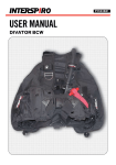
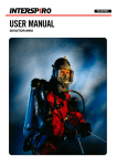
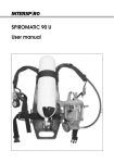
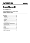
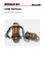
30249A01
user manual
90U S A a n d 9 0 U S A - S
INTERSPIRO’S LIMITED WARRANTY
INTERSPIRO warrants this product against failure to comply with INTERSPIRO’s
published specifications for the product and against defects in materials and
workmanship for a period of twelve (12) months after date of purchase. Within
that period, INTERSPIRO will, at its option, repair or replace the product or refund
your purchase price if INTERSPIRO determines the product does not conform to
INTERSPIRO´s specifications or is defective in material or workmanship.
To make a warranty claim, contact your authorized INTERSPIRO distributor or
INTERSPIRO directly. For telephone inquiries please have your product invoice or
other proof of purchase available. If you write, include proof of purchase and a
written explanation of the problem. Warranty servicing will be provided on-site or
at one of INTERSPIRO’s authorized service facilities, at INTERSPIRO’s discretion. If
shipment to an authorized service facility is required, shipping instructions will be
provided by INTERSPIRO or your authorized INTERSPIRO distributor. Do not ship
any product or component without shipping authorization. All shipping charges to
INTERSPIRO’s service facility must be prepaid by the customer.
This limited warranty does not apply if the product has been (I) involved in an
accident or subjected to misuse, improper maintenance or negligence; (II) altered
or repaired in any way that has, in INTERSPIRO’s judgement, adversely affected
its performance or reliability; (III) used in an application or for a purpose for which
the product was not designed or under stresses or conditions exceeding those
specified for the product; or (IV) damaged after leaving INTERSPIRO’s facility.
This limited warranty is valid only for the original purchaser, and is not
transferable.
IMPORTANT! This limited warranty is exclusive and is in lieu of all other
warranties, expressed or implied, including any warranty of merchantability or
fitness for a particular purpose. INTERSPIRO disclaims all other liabilities and
obligations, including, to the extent allowed by law, non-contractual liability for
personal injury or property damage based upon its negligence, strict liability or
any other ground. To the full extent allowed by law, and regardless of whether
liability is asserted on the basis of breach or warranty, negligence, strict liability,
breach of contract or otherwise, INTERSPIRO shall not be responsible for special,
incidental, consequential or punitive damages, including loss of property, loss of
profits or revenues, down-time costs and the cost of substitute equipment (some
states do not allow the exclusion or limitation of incidental or consequential
damages, so the above limitation may not apply to you).
This warranty gives you specific legal rights, and you may also have other rights
which vary from state to state.
90USA and 90USA-S
CAUTIONS AND LIMITATIONS
D. Air-line respirators can be used only when the respirators are supplied with
respirable air meeting the requirements of CGA G-7.1 Grade D or higher quality.
E. Use only the pressure ranges and hose lengths specified in the user’s
instructions.
I. Contains electrical parts which have not been evaluated as an ignition source in
flammable or explosive atmosphere by MSHA/NIOSH.
J. Failure to properly use and maintain this product could result in injury or death.
M. All approved respirators shall be selected, fitted, used, and maintained in
accordance with MSHA, OSHA, and other applicable regulations.
N. Never substitute, modify, add, or omit parts. Use only exact replacement parts
in the configuration as specified by the manufacturer.
O. Refer to users instructions, and/or maintenance manuals for information on use
and maintenance of these respirators.
S. Special or critical users instructions and/or specific use limitations apply. Refer
to instruction manual before donning.
S - Special or Critical User’s Instructions
Approved for respiratory protection during entry into or escape from oxygen
deficient atmospheres, gases, and vapors at temperatures above -25 degrees F (32 degrees C). Approved only when compressed air reservoir is fully charged with
air meeting the requirements of the Compressed Gas Association Specification G7-1 for Type 1, Grade D air or higher quality, as well as meeting a dew point level
of -65°F (-54°C) or dryer (24 ppm v/v or less), and a maximum particulate level of
5 mg/m3 air. The breathing air quality must be in accordance with NFPA 1989,
Standard on Breathing Air Quality for Fire and Emergency Services Respiratory
Protection. The container shall meet applicable DOT specifications.
Approved for respiratory protection during emergency entry into hazardous
atmosphere when supplied with respirable air at a pressure between 60 and 125
pounds per square inch and when using hoses with a total length between 25 and
300 feet, with a maximum of 12 hose lengths. Cylinder valve must remain closed
during supplied air use. If supplied air is terminated, open cylinder valve and
proceed to fresh air immediately. When used as a combination device, maximum
utilization of the apparatus air supply during entry:-With ventilation: 10% of the
rated capacity -Without ventilation: 20% of the rated capacity.
SC/PD/SA/ 60minute/ 4500 psi
SC/PD/SA/ 45minute/ 4500 psi
SC/PD/SA/ 30minute/ 4500 psi
SC/PD/SA/ 30minute/ 2216 psi
PROTECTION 1
X
X
X
X
ALTERNATE CYLINDER
ASSEMBLY
ALTERNATE
REGULATOR
ASSEMBLY
ALT. HARNESS ASSY.
BREATHING VALVE
X
X
X
X
X
X
X
X
X
X
X
X
X
X
X
X
X
X
X
X
X
X
X
X
X
X
X
X
X
X
X
X
X
X
X
X
X
X
X
X
X
X
X
X
ALTERNATE
AIRLINE HOSES
X X X X
X X X X X X X X
X X
X X X
X X X X X X X
X
X X X
X X X X X X X X
X
X X X
X X X X X X X
S.Special or critical users instructions and/or specific use limitations apply. Refer to users instructions before donning.
O.Refer to users instructions, and/or maintenance manuals for information on use and maintenance of these respirators.
N.Never substitute, modify, add, or omit parts. Use only exact replacement parts in the configuration as specified by the man
ufacturer.
regulations.
M.All approved respirators shall be selected, fitted, used, and maintained in accordance with MSHA, OSHA, and other applicable
J.Failure to properly use and maintain this product could result in injury or death
I.Contains electrical parts which have not been evaluated as an ignition source in flammable or explosive atmospheres by MSHA/
NIOSH.
E.Use only the pressure ranges and hose lengths specified in the user's instructions.
G-7.1 Grade D or higher quality.
D.Air-line respirators can be used only when the respirators are supplied with respirable air meeting the requirements of CGA
2. CAUTIONS AND LIMITATIONS
1. PROTECTION
SC = Self-Contained
PD = Pressure-Demand
SA = Supplied-Air
13F-381
13F-375
13F-420
13F-421
TC-
ALTERNATE MASK
ASSEMBLY
ATTACHMENT
SPECTACLE KIT
SPIROHATCH
RADIO
SPECTACLE KIT
SPECTACLE KIT
SPIROPASS
SPIRONET
VPU
ACCESSORIES
THESE RESPIRATORS ARE APPROVED ONLY IN THE FOLLOWING CONFIGURATIONS:
SPIROTEK, SPIROTEK T, T2, T3, T4, and T5 4515,4530,6630, 9030
90USA AND 90USA-S
OPEN-CIRCUIT, PRESSURE-DEMAND, ENTRY AND ESCAPE
SELF-CONTAINED BREATHING APPARATUS OR COMBINATION
SELF-CONTAINED BREATHING APPARATUS AND SUPPLIED-AIR RESPIRATOR
Savox 400 BM Radio Attach.
INTERSPIRO, INC.
10225 82ND AVENUE, PLEASANT PRAIRIE WI, 53158
PHONE 262-947-9901
Amplifier/ Radio Interface Kit
Cylinder Protective Sleeve
Radio Interface Kit
Voice Projection Unit Kit
Amplifier (VPU) Kit
X X X X
X X X X
X X X X
X X X X
X
X
X
X
X
X
X
X
X
X
X
X
X
X
X
X
X
X
X
X
X
X
X
X
X
X
X
X
X
X
X
X
X
X
X
X
X
X
X
X
X
X
X
X
X
X
X
X
X
X
X
X
X
X
X
X
X
X
X
X
336-890-083
336-890-233
336-890-222
336-890-462
336-800-353
55081-XX
97644-XX
336-190-004
336-190-456
336-190-792
96300-XX
336-890-230
336-190-002
336-890-006
336-890-456
336-890-138
95624
336-890-003
336-890-300
336-890-496
336-890-063
336-890-177
336-890-497
336-890-037
336-890-257
336-890-498
336-890-521
95806
95900-XX
95900-YY
97035-XX
97035-YY
97641-XX
97641-YY
55059-XX
55059-YY
346-190-350
95100-XX
336-980-009
336-980-010
336-980-011
336-980-031
336-890-255
334-190-040
341-190-001
341-190-002
341-190-326
346-900-080
336-890-355
95038-01
336-890-493
96470-01
96169
96918-01
96918-02
97227
97228
97695-XX
DEIJMNOS
DEIJMNOS
DEIJMNOS
DEIJMNOS
CAUTIONS / LIMITATIONS 2
Table of content
1. SAFETY NOTICE...................................................................................................... 6
2. cylinder mounting............................................................................................ 7
3. POSITIVE PRESSURE................................................................................................. 8
4. Connecting and disconnecting the face mask......................................... 9
5. apparatus pre-use check................................................................................. 11
6. donning............................................................................................................ 12
7. check before use.............................................................................................. 13
8. remove the apparatus..................................................................................... 14
9. clean and disinfect......................................................................................... 14
10.storage............................................................................................................. 18
11.Extra Air Connection..................................................................................... 19
12.Service and testing schedule........................................................................ 20
90USA-S Configuration
90USA Configuration
Fig. 1
user manual
90USA and 90USA-S
1SAFETY NOTICE
The product must only be used together with other approved INTERSPIRO products.
The product must only be used by personnel in good health and trained in the use
of respiratory protective equipment. Individuals with beards or large sideburns may
not obtain an adequate seal. The apparatus must be maintained, serviced and tested
as described in this user manual, INTERSPIRO service manuals and INTERSPIRO test
instructions.
INTERSPIRO IS NOT RESPONSIBLE FOR
MAINTENANCE AND REPAIRS NOT CARRIED OUT BY A HOLDER OF A VALID NTERSPIRO CERTIFICATE
COMBINATIONS OF PRODUCTS, UNLESS put to market by INTERSPIRO
CHANGES OR ADAPTATIONS MADE TO THE PRODUCT BY A THIRD PARTY
Changes to this document - necessitated by typographical errors, inaccuracies of
current information or improvements and changes of equipment - may be made
at any time without prior notice. Always refer to www.interspiro.com for product
updates, document updates and service bulletins. Exposure to extreme conditions,
such as asbestos, may require other actions than described in this manual. The
guarantees and warranties specified in the conditions of sale are not extended by
this Safety Notice.
The compressed air with which the cylinders are charged must meet the requirements
according to CGA G-7.1 Grade D or higher quality. Approved only when
compressed air reservoir is fully charged with air meeting the requirements of the
Compressed Gas Association Specification G-7-1 for Type 1, Grade D air or higher
quality, as well as meeting a dew point level of -65°F (-54°C) or dryer (24 ppm v/v
or less), and a maximum particulate level of 5 mg/m3 air.
The compressed air cylinders shall meet applicable DOT specifications.
The duration of a compressed air breathing apparatus depends on the volume of
air in the compressed air cylinder and the air consumption, which is specific to the
wearer and affected by work load. Compressed air cylinder durations are available
in 30 minute 2216 psi and 30,45 and 60 minute 4500 psi. Duration as listed are
the durations when tested to NIOSH standards.
If the ambient temperatures is 32°F or below external icing can cause malfunction
of the warning whistle. Under such circumstances the pressure gauge must be read
more frequently.
2
cylinder mounting
textile cylinder strap
1. Slide the cylinder through the cylinder strap.
2. Check the connection O-ring and screw the cylinder valve hand tight to the
cylinder connection of the manifold block [Fig. 2].
Fig. 2
3. Tighten the cylinder strap by pulling the free end – Do not over tighten
[Fig. 3]. If the strap is over tightened the buckle and backplate will be damaged.
Fig. 3
4. Close the lever on the buckle [Fig. 4].
Fig. 4
5. Secure the cylinder strap with the Velcro [Fig. 5].
Fig. 5
3
POSITIVE PRESSURE
90USA-S
Positive pressure is activated by closing the ambient air hatch by pushing the
exhalation valve cover against the face mask. To shut off positive pressure and
breathe ambient air, simultaneously press down the indicator arm and push the
exhalation valve cover away from the face mask. [Fig. 6 and Fig. 7]
Fig. 6 Activated positive pressure Fig. 7 Ambient air mode
90USA
Positive pressure is automatically activated by the first breath and can be switched off
manually by pushing the lever against the diaphragm housing. [Fig. 8 and 9]
Fig. 8 Activated positive pressure
Fig. 9 Positive pressure switched off
4Connecting and disconnecting the face mask
90USA-s - Connecting the face mask
1. Insert the breathing valve, with the ambient air hatch closed, into the face mask
[Fig. 10] and move the external speech cone down to lock the breathing valve in
position. In the correct position the lower lip of the speech cone covers the serial
number on the breathing valve. Tighten the hand screw [Fig. 11].
Fig. 10
Fig. 11
ATTENTION! When pushing the breathing valve in place, the fingers shall not be positioned on
the internal speech diaphragm since this can damage it.
2.
Connect the breathing valve to the breathing hose [Fig. 12].
NOTE! Some 90USA-S breathing valves with 90° by-pass may be equipped with
a quick connection at the by-pass and breathing hose.
Fig. 12
90USA-s - disconnecting the face mask
1.
2.
3.
Loosen the hand screw on the external speech cone. Pull out the hand screw and
move the external speech cone upwards to release the breathing valve.
Pull out the breathing valve from the face mask.
Disconnect the breathing valve from the breathing hose.
90USA - Connecting the face mask
1. Connect the breathing valve to the mask by pushing the valve into the
connection piece and turning it counter clockwise until the bayonet coupling is
locked. [Fig. 13]
Fig. 13
ATTENTION! When pushing the breathing valve in place, the fingers shall not be positioned on
the internal speech diaphragm since this can damage it.
2. Mount the external speech cone in the face mask. Tighten the hand screws by
hand. [Fig. 14]
Fig. 14
90USA - disconnecting the face mask
10
1. Loosen the two hand screws and remove the external speech cone.
2. Turn the breathing valve clockwise until it disengages from the bayonet coupling
and pull away from the mask.
5APpARATUS PRE-USE CHECK
1. Switch off positive pressure, see section 3.
2.
Open the cylinder valve fully.
3.
With the cylinder valve still open and the positive pressure turned off, read the
shoulder mounted pressure gauge.
NOTE! The cylinder valve pressure gauge and the shoulder mounted pressure gauge must read
full prior to use. Air cylinders of all SCBA shall be maintained at not less than 90 percent of
the rated pressure stamped on the cylinder.
4.
Close the cylinder valve. The needle of the shoulder mounted pressure gauge
should not move during one minute: If it does - indicating leakage - repairs should
be made by an authorized service personnel and the test repeated.
5.
With the cylinder closed, open the by-pass valve slightly in order to allow the air
to slowly evacuate. Read the pressure gauge when the audible alarm starts to
sound. The pressure gauge should read ¼ full. For the 90USA or 90USA-S 4500
psi cylinder pressure versions, the alarm should sound at approximately 1090
psi. For the 90USA or 90USA-S 2216 psi cylinder pressure versions, the alarm
should sound at approximately 580 psi.
6.
When the alarm sounds, turn the by-pass valve to the “OFF” position.
7.
Depressurize the system by turning on the positive pressure, see section 3.
11
6donning
1. 2.
Place the neck strap over the head.
3.
Fasten waist belt buckle and tighten. [Fig. 15 and Fig. 16]
4.
5.
Fig. 15
Fig. 16
Adjust the shoulder straps [Fig. 17], ensuring the majority of the weight is carried
on the hips. Readjust both waist and shoulder straps as necessary and tuck in
any loose straps.
Fig. 17
Switch off positive pressure, see section 3.
6.
Open the cylinder valve fully.
7.
Fit the face mask onto the head by first inserting the chin and then pulling the
head harness over the head. [Fig. 18]
12
Loosen the shoulder straps and the waist belt and don the apparatus. Initially
adjust the shoulder straps so as to position the pack on the lower back.
Fig. 18
8. Tighten the straps on the head harness, starting with the two at the bottom
[Fig. 19]. Pull the straps at an approximate angle of 45 degrees to the rear.
Do not overtighten the head harness.
Fig. 19
90USA-S:
9a.
Activate the positive pressure, see section 3.
90USA:
9b.
The positive pressure activates automatically.
7CHECK BEFORE USE
1. 2.
Hold your breath and listen for leakage, adjust the face mask if necessary.
Check that a strong air flow is heard when two fingers are inserted between the
sealing edge and face. [Fig. 20].
Fig. 20
3. Check the operation of the by-pass by opening the valve and ensure a good flow
of air into the face mask. Close the by-pass.
4. Check that the pressure on the pressure gauge reads full. The apparatus is now
ready for use.
13
8Remove the apparatus
1. Switch off the positive pressure, see section 3.
2. Open the buckles to release the head harness, loosen strap and remove the face
mask. [Fig. 21].
Fig. 21
3. Close the cylinder valve.
4. Unfasten the waist belt buckle and loosen the shoulder straps.
5. Remove the apparatus and activate the positive pressure to purge air from the
system. [Fig. 22 and 23]
Fig. 22
Fig. 23
9Clean and disinfect
1. Open the cylinder valve and check that there is pressure in the system before
cleaning.
Note: Having the cylinder valve open prevents water from entering the system and bubbles
will indicate any leaks in the system.
2. Place the apparatus except face mask and breathing valve, pressure gauge and
warning whistle into clean water.
3. Clean the apparatus with a brush and mild detergent.
4. Rinse the apparatus in clean water.
5. Dry
the apparatus and close the cylinder valve. Activate positive pressure to
purge air from the system.
14
90USA-S
ATTENTION! OBSERVE THAT THE EQUIPMENT MAY BECOME CONTAMINATED BY INFECTED BODY FLUIDS.
ALWAYS FOLLOW THE POLICY PRESCRIBED BY YOUR ORGANISATION. INTERSPIRO RECOMMENDS THAT THE
FACE MASK IS CLEANED AND DISINFECTED BY FOLLOWING THE PROCEDURE DESCRIBED BELOW. IF THE FACE
MASK IS SHARED BETWEEN DIFFERENT INDIVIDUALS IT IS ADVISABLE TO FOLLOW THIS PROCEDURE AFTER
EACH USE.
90USA-S - face mask
1. Disconnect the breathing valve as described in section 4.
2. Wash the face mask in lukewarm water (maximum 104° F) with a mild detergent
to remove dirt. Check that there are no remnants of dried body fluids.
3.
Disinfect the face mask, following the instructions supplied with the disinfectant.
4.
Rinse the face mask thoroughly with clean water.
5.
Shake the mask to remove excess water and dry the mask, avoiding direct heat
and sunlight.
In certain circumstances it is necessary to disassemble part of the mask in order to
clean it. Instructions for “Extended cleaning and disinfection” are available on
www.interspiro.com/support.
90USA-S - breathing valve
ATTENTION! WHEN CLEANING THE BREATHING VALVE IT MUST BE COMPLETELY DRY BEFORE IT IS
REASSEMBLED AND PUT BACK INTO SERVICE. REMAINING WATER MIGHT FORM ICE ON VITAL PARTS,
RESULTING IN MALFUNCTION OF THE BREATHING VALVE.
1. Clean the outside of the breathing valve with a cloth and lukewarm water
(maximum 104° F) with a mild detergent to remove dirt.
2.
Wipe the breathing valve clean with a cloth and clean water.
3.
Dry the breathing valve.
In certain circumstances it is necessary to disassemble the cover and diaphragm
in order to clean the breathing valve. Instructions for “Extended cleaning and
disinfection” are available on www.interspiro.com/support.
15
90USA
ATTENTION! OBSERVE THAT THE EQUIPMENT MAY BECOME CONTAMINATED BY INFECTED BODY FLUIDS.
ALWAYS FOLLOW THE POLICY PRESCRIBED BY YOUR ORGANISATION. INTERSPIRO RECOMMENDS THAT THE
FACE MASK IS CLEANED AND DISINFECTED BY FOLLOWING THE PROCEDURE DESCRIBED BELOW. IF THE FACE
MASK IS SHARED BETWEEN DIFFERENT INDIVIDUALS IT IS ADVISABLE TO FOLLOW THIS PROCEDURE AFTER
EACH USE.
90USA - face mask
1. Wash the face mask in lukewarm water (maximum 104° F) with a mild detergent
to remove dirt. Check that there are no remnants of dried body fluids.
2.
Disinfect the face mask, following the instructions supplied with the disinfectant.
3.
Rinse the face mask thoroughly with clean water.
4.
Shake the mask to remove excess water and dry the mask, avoiding direct heat
and sunlight.
90USA - breathing valve
ATTENTION! WHEN CLEANING THE BREATHING VALVE IT MUST BE COMPLETELY DRY BEFORE IT IS
REASSEMBLED AND PUT BACK INTO SERVICE. REMAINING WATER MIGHT FORM ICE ON VITAL PARTS,
RESULTING IN MALFUNCTION OF THE BREATHING VALVE.
1. Clean the outside of the breathing valve with a cloth and lukewarm water
(maximum 104° F) with a mild detergent to remove dirt.
2.
Wipe the breathing valve clean with a cloth and clean water.
3.
Unscrew the locking ring and remove the positive pressure attachment from the
valve housing. [Fig 24]
Fig. 24
4. Block the connection nipple and inlet with rubber plug.[Fig 25]
Fig. 25
16
5. Carefully remove the diaphragm unit from the cover by squeezing the thread of
the cover. [Fig 26]
Fig. 26
6. Remove the guide disc with positive pressure spring. [Fig 27]
Fig. 27
7. Remove the sealing disc from the diaphragm unit. [Fig 28]
Fig. 28
Warning: Do not disassemble the diaphragm unit further!
8. Wash the parts in lukewarm water (maximum 104° F) with a mild detergent to
remove dirt. Check that there are no remnants of dried body fluids.
9. Disinfect following the instructions supplied with the disinfectant.
10. Rinse
11. Dry
thoroughly with clean water.
the parts carefully.
12. Remove
the rubber plugs and check that there is no water ingress. In case of
water ingress connect to an air source to blow out any remaining water.
13. Place
the guide disc with positive pressure spring in the cover. [Fig 27]
14. Assemble
the sealing disc with the diaphragm unit. [Fig 28]
17
15. Place
the diaphragm unit onto the positive pressure spring and press straight
down until it snaps into the cover [Fig 26]. Do not twist the spring.
16. Push
gently on the guide pin to check that the diaphragm moves easily.
17. Make
sure the O-ring is correctly seated in the groove on the diaphragm unit,
lubricate if necessary.
18. Turn
the lever to the position for activated positive pressure (as described in
section 3).
19. Mount
the locking ring onto the valve housing.
[Fig 24]
20. Centre
the guide pin on the positive pressure attachment in the oblong hole of the
valve insert lever.
21. Screw
the locking ring together with the positive pressure attachment [Fig 24].
The locking ring, not the positive pressure attachment, shall be rotated.
10Storage
Store in a cool, dry and dust-free environment. Protect rubber parts from direct
sunlight, UV radiation and direct heat. When the regulator unit is not connected the
cylinder valve shall always have a protective plug.
During storage, the breathing valve shall be in the position for activated positive
pressure, see section 3.
18
11Extra Air Connection
The 90USA-S and 90USA can be equipped with an extra-air manifold fitted with a
“IS”-type quick connection for extra air.
The connection can be used to:
• Feed the apparatus with medium pressure air from an external air source.
• Connecting a chemical suit ventilation system.
• Connecting rescue hoses between two apparatus.
• Connecting the rescue mask REVITOX.
To take out air from the apparatus to feed a ventilated chemical suit/rescue hose or
Revitox extra mask, a special female coupling with a non-return valve opener is used.
This device opens the non-return valve in the male coupling mechanically. This female
coupling must not be used in airline systems as the non-return valve must be able to
close if the airline hose is cut off by any means. The female couplings with a nonreturn valve opener shall only be used on shorter hoses that can be controlled and
the couplings disconnected if necessary.
Connection
The securing ring on the female coupling must be open before connection. Press the
female onto the male and secure the fitting by screwing up the locking ring.
Disconnection
Unscrew the locking ring and pull back the movable sleeve on the coupling.
19
12 service and testing
Service and testing shall be performed according to the minimum requirements
described in the “Service and Testing Schedule” with publication number 97307.
Local requirements may differ due to regulations and environmental conditions.
In case of doubt consult your local INTERSPIRO representative.
The “Service and Testing Schedule” is available on the INTERSPIRO website
www.interspiro.com .
20
AUSTRIA
INTERSPIRO GesmbH www.interspiro.de
Feldbacher Str. 3 A-8200 GLEISDORF AUSTRIA
TEL +43 (0)311 236 133 FAX +43 (0)311 236 133 22 E-MAIL [email protected]
GERMANY
INTERSPIRO GmbH www.interspiro.de
Postfach 1220 D-76691 FORST/BADEN GERMANY
TEL +49 (0)7251 8030 FAX +49 (0)7251 2298 E-MAIL [email protected]
SWITZERLAND
INTERSPIRO AG www.interspiro.de
Güterstraße 47 CH-4133 PRATTELN SWITZERLAND
TEL +41 61 827 99 77 FAX +41 61 827 99 70 E-MAIL [email protected]
THE NETHERLANDS & BELGIUM
INTERSPIRO BV www.interspiro.nl
Televisieweg 113 NL-1322 BD ALMERE NETHERLANDS
TEL +31 (0)36 5363103 FAX +31 (0)36 5384809 E-MAIL [email protected]
NORTH & SOUTH AMERICA
INTERSPIRO Inc. www.interspiro-us.com
10225 82nd Avenue PLEASANT PRAIRIE WI 53158-5801 USA
TEL +1 262 947 9901 FAX +1 262 947 9902 E-MAIL [email protected]
UNITED KINGDOM & IRELAND
INTERSPIRO Ltd. www.interspiro.com
7 Hawksworth Road Central Park TELFORD Shropshire TF2 9TU UNITED KINGDOM
TEL +44 (0)1952 200 190 FAX +44 (0)1952 299 805 E-MAIL [email protected]
SCANDINAVIA, ASIA/PACIFIC & MIDDLE EAST
SWEDEN
NORDIC & EXPORT SALES DIVISION www.interspiro.com
Box 10060 S-181 10 LIDINGÖ SWEDEN
TEL +46 8 636 51 00 FAX +46 8 765 48 53 E-MAIL [email protected]
MALAYSIA
NORDIC & EXPORT SALES DIVISION www.interspiro.com
305 & 305A Lorong Perak Taman Melawati 53100 KUALA LUMPUR MALAYSIA
TEL +60 3 4105 8122 FAX +60 3 4105 3122 E-MAIL [email protected]
PART NO. 30249A01
CENTRAL EUROPE