1
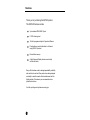
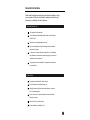
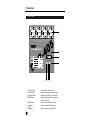
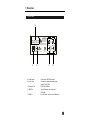
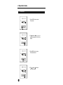
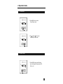
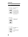
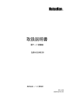
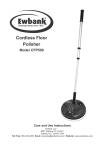
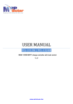
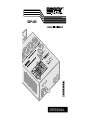
R
DDP-405
USER'S MANUAL
Contents
Features 1
General Instructions 2
1. Overview 3
1.1 Front Panel 3
2 Rear Panel 4
2. Operation Guide 5
2.1 Chase Mode 5
2.2 Receive Mode 6
Technical Specifications 8
DDP-405
4 CHANNEL DIGITAL
DIMMER PACK
Improvement and changes to
this manual, specifications
and design, may be made at
any time without prior notice.
R
ALL RIGHTS RESERVED.
The Pioneer of
Entertainment Lighting Industry
Features
Thank you for purchasing this BOTEX product.
This DDP-405 features include:
3-pin standard DMX IN/OUT ports.
0-100% dimming level
16 built-in programs subject to Speed and Dimmer
Provide dimmer control information to 4 channel
using DMX-512 protocol.
Power failure memory.
4 digits Segment Display shows current activity
and function state.
Every effort has been made to design dependability, reliability
and comfort into each unit. New products are being designed
constantly to meet the needs of both entertainment and the
lighting industry. We welcome your comments about our
product and services.
It is both a privilege and a pleasure serving you.
1
General Instructions
Please read through this operating instructions before installing or using
your new product. After you have finished reading the instructions, put
them away in a safe place for future reference.
Safe and Efficient Use
This product must be earthed.
Do not make any inflammable liquids, water or metal objects
enter the unit.
Take care not to damage the power cord.
No user serviceable parts inside, always consult authorized
personnel for repairs.
In the event of a malfunction(burning smell, etc.), immediately
stop operation, disconnect the power supply plug, and consult
authorized service personnel.
To prevent fire or shock hazard, do not expose this product to
rain or moisture.
Product Care
This product is intended for indoor use only.
Provide occasional ventilation during use.
Unplug the power plug from the sockets when not using the
unit for extended period.
Do not use the unit in places subject to excessive humidity,
vibration or bumps.
Place this unit in a stable location.
Do not dismantle or modify the unit.
2
1. Overview
1.1 Front Panel
1
1
2
3
4
OUTPUT: 5A/CH , TOTAL 16A Max.
1
DMXSignal
MODE
MENU
DISPLAY
2
3
8888
4
2
Receive
Chase
3
CH:02 CH:04
TOTAL DMX CHANNEL
RECEIVE
DMX CHANNEL
7
CHASE PROGRAM
SP:99
CHASESPEED
:000
p
CHASEDIMMER
MODE MENU
p
CHASE
4 5
1. Channel Output
2. Channel LEDs
3. Segment Display
4. MODE button
5. MENU button
6.
button
7.
button
3
6
5 A per channel, total 16 A max.
Shows the intensity of the channel in use.
Shows current activity or function state.
Press to select operating mode between
Chase and Receive.
Press to select desired menu setting.
Press to increase the display value.
Press to decrease the display value.
1. Overview
1.2 Rear Panel
10
FUSES: F6.3A 250V 5x20mm
1
2
3
DMX IN
CAUTION
4
DMX OUT
3
3
1=Ground
RISKOFELECTRICSHOCK
DISCONNECTINPUTPOWER
BEFOREOPENING
2=Data3=Data+
WARNING:
THISAPPARATUSMUSTBEEARTHED
N'OUVREZPAS..RISQUEDECHOCELECTRIQUE
2
1
2
1
OFF
ON
MADEINCHINA
POWER
8
8. Power Switch
9. Power Cable
10. Channel Fuse
11. DMX Out
12. DMX In
POWER INPUT: AC 230V~50Hz,16Amax.
9
23-001-0697
11
12
Press to turn ON/OFF the power.
Connect to an appropriate power outlet
rated AC 230V~50Hz.
F6.3A 250V 5x20mm
3-pin XLR female, used to transmit
DMX data.
3-pin XLR male, used to receive DMX data.
4
2. Operation Guide
2.1 Chase Mode
1
2
3
4
p02
DMX Signal
Receive
1. Press MODE button to select
Chase mode.
Chase
MODE MENU
1
2
3
4
p05
DMX Signal
Receive
Chase
2. Tap button(or button ) to your
wanted chase within 01-16 built-in
chases.
MODE MENU
1
2
3
4
sp15
DMX Signal
Receive
3. Press MENU button to enter
Chase Speed mode.
Chase
MODE MENU
1
DMX Signal
2
sp32
MODE MENU
5
3
4
Receive
Chase
4. Tap button(or button) to
your desired speed.
2. Operation Guide
2.1 Chase Mode
1
2
p
DMX Signal
3
4
025
Receive
5. Press MENU button to enter
Chase Dimmer mode.
Chase
MODE MENU
1
2
3
4
6. Tap button(or button) to set
the intensity for the chase.
p
DMX Signal
059
Receive
Chase
MODE MENU
2.2 Receive Mode
1
DMX Signal
2
3
CH02
4
Receive
Chase
1. Press MODE button to select Receive
mode, the Segment Display shows CH:01,
CH:02 or ch:04.
MODE MENU
6
2. Operation Guide
2.2 Receive Mode
1
2
3
ch01
DMX Signal
2. Tap
button or
channel settings.
4
Receive
Chase
MODE MENU
1
2
3
When c h: 0 1 appears, overall channel
output is controlled by one DMX channel;
when c h: 0 2 appears, every two channel
output is controlled by one DMX channel;
when c h: 0 4 appears, each channel output
is controlled by one DMX channel.
4
a025
DMX Signal
button for desired
Receive
3. Press MENU button to set DMX
initial address for the channel.
Chase
MODE MENU
1
DMX Signal
2
a025
MODE MENU
7
3
4
Receive
4. Tap
button or
channel settings.
button for desired
Chase
If you set address 25 for the first channel,
then 26, 27 and 28 for the rest channels
in sequence.
Technical Specifications
Power Input ........................................................... AC 230V~50Hz, 16 A max.
Channel Output ............................................. 5 A per channel, Total 16 A max.
DMX OUT ........................................................................... 3-pin XLR female
DMX IN .................................................................................. 3-pin XLR male
Channel Fuse ................................................................. F6.3A 250V 5x20mm
Dimensions ............................................................................. 212x188x71mm
Weight .................................................................................................... 2.4 Kg
8
R
ALL RIGHTS RESERVED
Rev 1.0 May, 2000
24-004-0333