1
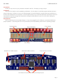
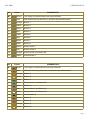
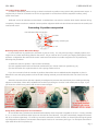
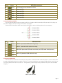
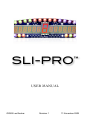
SLI-PRO™
USER MANUAL
©2009 Leo Bodnar
Revision 1 11 November 2009
SLI-PRO
USER MANUAL
Introduction
Thank you very much for your purchase or interest in SLI-Pro. We hope you enjoy using it.
Installation
Your SLI-Pro is ready to use immediately as delivered. You can plug it in, install the support software and start
using it right away. However, to use it to its full advantage it is recommended to connect buttons and switches to it.
SLI-Pro uses USB power for its operation. Even though its level is only 5 Volts and USB host must limit the current in
case of short circuit it is strongly recommended to unplug the USB cable from your PC or hub when making any
connections to the SLI-Pro.
Requirements
SLI-Pro requires power for its bright displays. It has to be plugged into PC USB port or powered USB hub for
proper operation. Connecting SLI-Pro to non-powered hub will most definitely prevent it from operating properly.
“Speed” display
Left info lights
Standard mini-USB B socket
“Time” display
Engine RPM lights
Gear display
Alternative USB connection
Right info lights
External LEDs connection
Connections for buttons, switches and analogue inputs
Page 2
SLI-PRO
No.
▶1
Colour
+5V supply for potentiometer and rotary switches
2
Red
GND (shared among all buttons, switches and potentiometers)
3
Orange
Button 1
4
Yellow
Button 2
5
Green
Button 3
6
Blue
Button 4
7
Violet
Button 5
8
Grey
Button 6
9
White
Button 7
10
Black
Button 8
11
Brown
Rotary switch 1
12
Red
Rotary switch 2
13
Orange
Rotary switch 3 (or Button 29)
14
Yellow
Potentiometer 1
▶1
USER MANUAL
CONNECTOR 1
Brown
No.
Colour
CONNECTOR 2
Brown
+5V supply for potentiometer and rotary switches
2
Red
GND (shared among all buttons, switches and potentiometers)
3
Orange
Button 9
4
Yellow
Button 10
5
Green
Button 11
6
Blue
Rotary switch 4 (or Button 30)
7
Violet
Button 12
8
Grey
Rotary switch 5 (or Button 31)
9
White
Rotary switch 6 (or Button 32)
10
Black
Potentiometer 2
11
Brown
Button 13
12
Red
Button 14
13
Orange
Button 15
14
Yellow
Button 16
Page 3
SLI-PRO
USER MANUAL
12-position Rotary Switch
In order to dramatically reduce wiring we have introduced 12-position rotary switch with potentiometer output. It
requires only 3 wires for connection to SLI-Pro as opposed to 13 wires that would be required if ordinary rotary
switch were used.
GND and +5V for all switches can be shared - extended from one switch to another which further reduces wiring
complexity. Please note that to maintain correct position alignment GND wire should be connected to the switch pad
marked with a dot.
Connecting 12-position rotary switch
Dot indicates GND connection
to GND
to rotary switch input
to +5V
Reducing Rotary Switch Movement Range
In some instances 12 positions for one switch is just too many. You may end up using 4-5 display options and
might want to create neat looking label for the switch. All you need to do is re-order your display data options in the
software configuration file and limit the switch mechanical movement to smaller range then full 12 positions by
following this procedure:
1) rotate the switch to position 1 (full counter-clockwise)
2) insert supplied washer tab into the hole marked with your chosen maximum position (e.g. 6)
3) insert the switch into a panel and fix it with a spring washer and nut
If you do not need to limit the number of positions then either remove tabbed washer altogether or place it
between the nut and spring washer so that the tab is facing towards you and interlocks with one of the nut's flat
sides.
Attention: the switch front side has a plastic pin designed to prevents the switch body from rotating and losing
alignment with labels. Either drill a suitable hole to fit this pin through or remove it with a knife, file or snips. If you
just insert the switch into a panel it will not be mounted straight.
Using Rotary Switch Inputs 3 To 6 For Buttons
All connected rotary switches are detected automatically when the power is applied to SLI-Pro. If rotary switches
3, 4, 5, or 6 are not used then these inputs can be used for extra buttons. They are automatically mapped to buttons
29, 30, 31 and 32 respectively. To avoid any erroneous activation of switch function on these inputs during the power
up configuration the buttons connected to these inputs must be of “momentary ON” type. I.e. the inputs should be in
open state when SLI-Pro powers up.
Page 4
No.
▶1
Colour
EXT.LEDs connector
Green
+5V (shared among all external LEDs)
2
Blue
External LED 1
3
Violet
External LED 2
4
Grey
External LED 3
5
White
External LED 4
6
Black
External LED 5
Connecting External LEDs
Up to 5 external LEDs can be connected to SLI-Pro. Together with 6 information LEDs on the SLI-Pro they can
be used to display various warning or information messages.
External LED connections have internal current limiting to 15mA so limiting resistor is not necessary.
External LED 1
External LED 2
+5V
External LED 3
External LED4
External LED 5
No.
▶1
Colour
USB connector
Green
USB D+ (standard USB cable wire green)
2
Blue
USB D- (standard USB cable wire white)
3
Violet
4
Grey
5
White
6
Black
USB GND (standard USB cable wire black) and USB cable shield (screen)
USB +5V (standard USB cable wire red)
Connecting USB Cable
SLI-Pro can be connected to PC USB port using either a standard USB A to Mini-B cable or custom made cable
through a dedicated socket on the back of SLI-Pro. It is recommended to use standard USB cable as a basis of your
own wiring between the SLI-Pro and a PC. Using arbitrary cables might cause problems with power and USB data
integrity.
USB A to Mini-B cable
Page 5