1
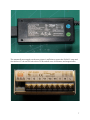
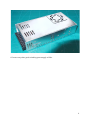
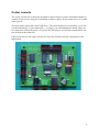
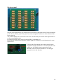
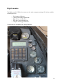
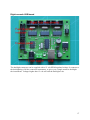
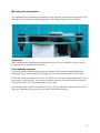
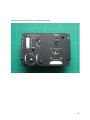
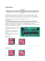
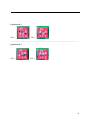
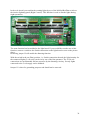
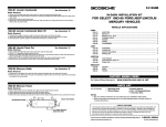
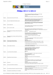
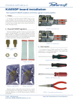
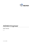
Aircore and Indicator Controler User manual v1.3 Created by Eagle and Falcas CAUTION AIC circuit boards are electrostatic sensitive devices. This means you can damage your board if you don’t take precautionary measures. Make sure you are not electrostatically charged before working on the PCB’s. You can do this by grounding yourself and use ESD-approved materials. If you don’t have them at least discharge yourself by touching a ground wire of your electrical installation. 2 Contents INTRODUCTION. ................................................................................................................... 5 INSTALL AND UNINSTALL. ............................................................................................... 5 THE HARDWARE. ................................................................................................................. 6 USB devices. ....................................................................................................................... 6 Power supplies. .................................................................................................................. 6 CENTER CONSOLE ............................................................................................................... 9 Caution panel. .................................................................................................................. 10 Engine device. .................................................................................................................. 11 Fuel flow device................................................................................................................ 15 RIGHT CONSOLE ................................................................................................................ 16 Right console USB board ................................................................................................. 17 Mounting the instruments ................................................................................................. 18 Fuel Quantity Indicator .................................................................................................... 18 Other right aux instruments ............................................................................................. 20 Hydraulics A and B .......................................................................................................... 20 EPU Fuel and Oxygen ...................................................................................................... 21 Cabin Altitude .................................................................................................................. 21 Compass ........................................................................................................................... 22 Master Caution Panel ...................................................................................................... 23 LEFT CONSOLE ................................................................................................................... 26 Left console USB board.................................................................................................... 26 CMDS panel ..................................................................................................................... 27 UHF panel ........................................................................................................................ 29 Aux Comm panel .............................................................................................................. 31 Trim panel ........................................................................................................................ 33 LIGHT BOARDS. .................................................................................................................. 37 THE SOFTWARE.................................................................................................................. 40 Main program settings. .................................................................................................... 40 Devices. ............................................................................................................................ 41 SharedMemory. ................................................................................................................ 41 Calibration ....................................................................................................................... 42 Left instruments. ............................................................................................................... 42 Engine instruments. .......................................................................................................... 44 Right Aux instruments. ..................................................................................................... 44 Left Tab. ........................................................................................................................... 45 Special features left console. ............................................................................................ 46 Center Tab. ....................................................................................................................... 46 Special features center console. ....................................................................................... 47 Right Aux Tab. .................................................................................................................. 47 DED and PFL................................................................................................................... 47 FAQ. ........................................................................................................................................ 48 CREDITS. ............................................................................................................................... 48 3 4 Introduction. There are lots of different hardware options to choose from if you are building your own Viper cockpit. So why would you choose for the AIC hardware and software? The main difference between AIC and other projects is that AIC is completely made for Falcon4. It is also designed to be plug and play as much as possible. The hardware is designed for a block 50/52 Viper and all pcb’s fit Mike “Kabar”Williams panels. The right aux instruments can also be mounted using the original clamp holes. This makes installation real easy. Mike’s panels, instrument dials, needles and bezels are NOT included in the AIC hardware. They have to be obtained from Mike separately. You can find more info here: http://shop.viperpits.org/ The AIC software will take care of everything and will be the only software that you need to drive your lights and indicators. For the flight instruments that are found on the center console (Spd, Alt ect) we recommend that you use Lightning’s MFDE software. Also AIC will only do outputs and does not handle switch inputs. For hardware that will handle keystrokes and joystick axes, we advice you to use hardware like the X-keys and the joystick device made by Leo Bodnar. This manual will explain how to use the software and will show you the benefit of the AIC hardware. Install and uninstall. For now we have chosen not to make an installer. The program is so small, that it would be more work to use an installer then to unpack the rar file. Unpack the rar file at any place you like. To uninstall the software, just delete the whole directory. 5 The Hardware. The AIC hardware comes with different components. For reference I will first explain the different components so that you know what we are talking about. USB devices. There are 3 main USB devices that will run your whole cockpit, the left, center and right aux devices. All the sub devices will be connected to these USB devices. The AIC hardware has been designed with the idea that you build these USB devices into the 3 main parts of your cockpit, the left, center and the right console. By doing so, your cockpit will have as few cables running from left to right as possible. It also makes sure that the cockpit is easy to move. But you can also build the USB devices outside of your cockpit on a central place. Connection of the boards and instruments is straigforward, using the supplied flatcables. Just make sure you connect the right board to right connector. All connectors on the pcb are named, according to the panel to which they connect. Connecting devices to the wrong connectors can damage the USB boards and/or devices. Power supplies. A book can be written about using power supplies. AIC hardware only needs 12 volt to operate correctly. I recommend using a 12 volt, 3 to 4 amps powersupply per USB controller. These are easily available as laptop powersupplies or monitor powersupplies. Never use crappy, unreliable, unstabilised powersupplies as these will cause trouble for sure. The next pictures show a few examples good powersupplies. 6 The meanwell powersupply on the next picture is sufficient to power the Full AIC setup and also delivers 5 volt and 24 volt to drive LEDs and all sorts of indicators and magswitches. 7 Of course any other good switching powersupply will do. 8 Center console The center console device has been designed so that it will give you the maximum amount of outputs in case you are using it for a desktop cockpit or choose for the center device as a stand alone system. The next picture shows the center USB device. The board needs to be powered by 12v dc. Be careful with polarity. If you connect the +/- wrongly, you could damage the board. There are two options to connect the power. Or you use the jack plug or you use the terminal block. Do not use both at the same time. It has connectors for the engine console, the fuel flow indicator and one connection for the light boards. 9 Caution panel. Like the other light boards, the caution panel is basically a light board, but it has been adapted to fit with the caution panel. The option to connect magnetic switches or other indicators has been removed. The Caution Panel also needs to have an id set. On the back you find the same dipswitches as on the normal light boards. If connected to the center console board an ID of 4 should be set. If you use the caution panel together with the right aux USB device, the id needs to be set to light board 1. Like the other light boards, the caution panel has the bright/dim function build into it. On the backside of the board, you will find the same connection for the Mal/ind switch and also the dimmer to set the light intensity for the dim function. 10 Engine device. The engine device holds 4 aircores that drive the Oil pressure, Nozzle, RPM and the FTIT. It also contains backlights (led) to light the instruments. A separate manual will describe how to build the package when you use Mike’s engine console. It also contains the explanation how to calibrate this device, so pay special attention to this! Connecting the engine device to the center USB device is very simple. Just plug in the flat cables that come with the package. The device will get all the power it needs from the USB device. 11 On the backside of the PCB you will find a little blue trimmer. This trimmer is used to set the backlight intensity when internal dimming is selected. Dimming is also possible through the dimming connector on the USB controller. You can apply a 12 volt PWM signal on this connector to dim the backlighting externally using your own PWM controller. In that case you have to set the red jumpers to external dimming. 12 13 External backlighting connector on the center USB controler: Calibration After installing and connecting the instruments they have to be calibrated. See the software section on how to perform the calibration. 14 Fuel flow device. If you install the fuel flow indicator in your pit, be careful not to short circuit the board!!! The lines on the pcb are very close to the screw holes and the screws could make contact. Use isolating nylon rings to prevent short circuit!!! The fuel flow device has osram digital displays. This device is truly a plug and play indicator. Just connect the flat cable that comes with the package and you are done. The fuel flow indicator gets its power directly from the center USB device, so there is no need for an extra power supply. You can adjust the brightness of the display by use of the dimmer on the back. 15 Right console The Right console USB device connects to the main computer running AIC software and the following devices: - Fuel Quantity Indicator Caution panel and/or lightboards Hydraulics A and B meters EPU and Cabin Altitude meter Compass and Oxygen Indicator. Connections are straightforward, using flatcables. 16 Right console USB board The backlight connector can be supplied with a 12 volt PWM regulated voltage. It connects to the backlighting of all the connected instruments, so gives you a simple means to backlight the instruments. Voltages higher then 12 volt will ruin the backlight Leds. 17 Mounting the instruments The instruments are mounted on the backside of the right aux panel using the supplied screws and spacers, according to the following picture. The original clamp holes can be used. Calibration After installing and connecting the instruments they have to be calibrated. See the software section on how to perform the calibration. Fuel Quantity Indicator The Fuel Quantity Indicator displays the total amount of fuel on the Osram Displays and remaining Fuel in the fuel tanks, according to the Fuel select Switch on the center console. Before use it has to be calibrated, via the AIC mainscreen. Because of the construction of the meter there is some parallax, so it it best to calibrate the meter from the position you will be flying Falcon. This is to avoid reading the wrong values. But remember, the needles are mainly used to give you an indication of the fuel level and to show any imbalance, not to give an exact value of the amount of fuel. 18 The intensity potmeter can be used to set the Osram intensity to your desired intensity. 19 Other right aux instruments The other Right Aux instruments, with exception from the compass, are all mounted and connected the same way as the Fuel quantity indicator. Hydraulics A and B 20 EPU Fuel and Oxygen Cabin Altitude 21 Compass The Compass is a different story. It uses a special aircore with the connections on the bottomside. This aircore can also be ordered from me. The leds for the backlighting are delivered, but not mounted, due to transportation damage. Before mounting the pcb on Mike’s compass, or fitting it into a real, modified, compass housing, the leds have to be soldered. When soldering the leds, please notice the flatside on the pcb printing and on the leds itself. These have to align. When aligned properly solder the leds to the board at the desired height to lighten the compass dial. You can paint the leds black on the front side, to avoid light shining out the wrong direction. 22 Master Caution Panel The Master Caution panel can be connected to the USB controller, using the supplied flatcable. It is also powered through the USB board, so doesn’t need an additional powersupply connection. You only have to keep in mind, that when all leds are in the on position (for instance during a lights test) a lot of current is drawn. It is therefore recommended to not exceed a 1 minute duration to avoid overheating the USB board. 23 The Master Caution board comes with a connector to which you can connect a dimming switch. When the two connections are connected together the leds go into a dimmed setting. The intensity can be set with the potmeter. Standard address setting of the Master Caution board is board 1. Below you see the dipswitch settings according to this address. 24 25 Left console The Left console USB device connects to the main computer running AIC software and the following devices: - CMDS panel UHF panel Aux Comm panel Trim panel Lightboards (up to 4 lightboards can be connected) Connections are straightforward, using flatcables. Left console USB board The backlight connector can be supplied with a 12 volt PWM regulated voltage. It connects to the backlighting of the Trim panel needles, so these can be dimmed independently from the panel backlighting. Voltages higher then 12 volt will ruin the backlight Leds. The CMDS supply voltage select jumper can be used to set the voltage to either 5 or 12 volt. Select 5 volt when you use a Jay’s CMDS panel (this is the Beta Innovations setting). AIC CMDS panel uses 12 volt setting. 26 CMDS panel The Osram displays are blanked by shorting the middle and upper connection of the switch connections on the pcb. It is best to use a dual pole, dual throw switch to make this happen. One side of the switch can be connected to your key encoder and the other half to the connections on the pcb. This way you can give the command to Falcon and turn the Osram displays off. 27 The next picture shows an example of connecting a Dual Pole Dual Thrown (DPDT) switch to power the Osram’s at the same time with sending a keystroke to Falcon. 28 UHF panel The UHF panel displays a fixed frequency, until the values are added to the shared memory in future Falcon versions. In order for the UHF panel to function properly the UHF panel has to be initialized and the display on connector has to be shorted. The display on connector can be wired to the UHF power switch as an additional contact. This way the display will be turned on, together with the command to Falcon. Initialisation always happens when the Left console USB board is powered up. So under normal circumstances it will always function properly. In any case of the displays not sowing data, first make sure the display power connector on the backside of the board is shorted. If there is still no data then, re-power the Left console USB board and you should see a self-test running. The displays are also dimmed when AIC software is running and Falcon is not running. 29 The dim switch connector can be used to put the UHF displays in a dimmed mode. The intensity can be set using the dim intensity potmeter, after shorting the dim switch connector. The backlight connector can be used to input a 12 volt PWM regulated signal to regulate the backlight Led intensity. The display on connector turns the 7-segments displays on, when shorted. 30 Aux Comm panel The AuxComm panel is connected in the same way as the CMDS panel. 31 Switch used for the Tacan channels: Farnell number: 957-5057 Channel inlay can be ordered from Mike “Kabar” Williams. 32 Trim panel To finish the trim pcb with Mike’s panel some extra work needs to be done. I will describe the way how to do this here: - Spray paint the borders of the pcb black Glue the trim needle indicators to the pcb, using the panel for proper alignment. Install 4 countersunk screws with spacers on the other side if you want to use 25 pins sub d connectors to wire the pcb. Connect the pcb to the USB controller and power it up, starting AIC. Place the needles in the middle position and calibrate the needles. - Place the yaw trim potentiometer and AP DISC switch 33 - Glue the potmeter holders to the backside of the panel. It is possible you have to widen the slot to make your potmeters fit. If so, do this before glueing them to the panel. - Place the lenses in the panel and tip the white spots black if necessary. - After drying of the paint, remove the protective paper. 34 - Place the trimwheels on the potmeters. - Place the assemblies in the trimpanel and fasten the nuts. Align the trimwheels and secure them to the potmeter shaft. - Now wire the potmeters and switches as desired. Calibration After installing and connecting the instruments they have to be calibrated. See the software section on how to perform the calibration. 35 And here is the finished result. A functional trimpanel. 36 Light boards. CAUTION NEVER place a 12-24 volt select jumper when on the same 8-output bank the resistor network is installed. This will absolutely destroy the installed driver chip. The light boards are connected to the USB devices (left or center) and will drive LEDs, magnetic switches and other devices that need 5 – 24v to be turned on or off. A separate manual will explain how to connect all the lights and magnetic switches to the light boards. The light boards can be daisy chained to a maximum of 4 devices. So as an example: You can hook up 4 light boards to the center USB device and run all your lights from the center USB device. This setup will give you 128 channels to work with. The software supports up to 2 light boards on the left device, another 64 channels. Then you got the option to connect 1 caution panel to the right aux device, which has another 32 channels. With all the 3 USB boards, you can hook up a total of 6 light boards and 1 caution panel. This will give you 224 channels to work with. The light boards need to have an id set to recognize them as board nr 1, 2, 3 or 4. Red dipswitches on the light board itself will give you the option to set the ID. Be careful to check which dipswitch is SW_1 and SW_2 Light board 1 SW_1: SW_2: ————————————————————————————————————— Light board 2 SW_1: SW_2: 37 Light board 3 SW_1: SW_2: ————————————————————————————————————— Light board 4 SW_1: SW_2: 38 In the real aircraft you can dim the warning lights by use of the Mal Ind Brt/Dim switch on the interior lightning panel (Right Console). This function is used to dim the lights during night operations. The same function has been added to the light board. If you would like to make use of this function, connect a switch to the Switch connection on the light board as seen on the picture above. Removing jumper J2 will enable the dimming function. With the switch in the on (Dim) position, i.e. Switch connection shorted, the light intensity for the connected lights (5 volt only) can be set by use of the blue potmeter. The 12-24 volt connections are not dimmable and are surpasses by the dimming circuitry. So only lights connected to the 5 volt supply can be dimmed. Jumper J1 is there for grounding purposes and should not be removed. 39 The software. On the main screen you can see what all the instruments and digital displays should be showing. You can also select the main options for the software. Normally you will not see this page much. After you have started the program, the program will do everything automatically. Main program settings. The program has some basic settings that you can see in the picture to the right. You can choose if you want to have AIC run at startup. If so, you also have the option to automatically run AIC minimized. “Blinking lights” is an option that will let you make certain lights blink. For now, only lights on the center console will have this option. This will be a great help for those who have been struggling with special leds. The Launch, Outer and Inner marker have a slider to regulate the blinking speed. See the “Center tab” for details. The “Use Logitech DED/PFL” option is there for those who want to use the G-15/Z-10 as a DED or PFL. If you don’t use this hardware, switch off this function. In this case AIC uses less resources. 40 If you are using the G-15/Z-10, the Logitech software is also trying to start AIC. Have a look in the Logitech software. After you have run the AIC for the first time while the Logitech software is running, you will find 2 new programs, DED and PFL. Under the DED and PFL program you can select if the Logitech software should start AIC upon windows start. The “Master Caution delay” function has been build in because the real master caution has a delay before the light comes on. If you want to have the same delay as in the real one, you can select this option on. Devices. In the device section you can check if your hardware is connected correctly. The box turns green if a USB device is properly connected. SharedMemory. AIC will detect if Falcon is running by itself and start updating the indicators immediately. It will also detect which flavor of Falcon you are using and will adjust accordingly. If you want to calibrate any instrument or run the test function and Falcon is running, you have to stop the sharedmemory process first. If you do so, the calibration options will become available. If Falcon is not running you can also select these options. To check if all your instruments are working as they should, you can use the test function. The test function will let the instruments rotate and will show numbers in all the displays. The “Zero indicators” button will bring all the indications to there zero position. When you start the reading of the sharedmemory again, all the indicators will be updated. With the polling slider you can choose how long the program waits before it starts the update process again. This time is in msec. A larger number means that the program hold its breath for a longer time before it continues. This also means that with a larger number the processor is being used less. Use this slider to find a nice 41 balance between fps and instrument update. 30ms is fine in most instances. The “All Lights On” button will switch all the light channels on. If you have any lights or magnetic switches connected, they will light up. More precise control over the lights can be found on the respective left, centre and right tabs. The needles of the fuel totalizer will be reset every time AIC will get a new connection to the right aux device. If you have the need to reset these needles, you have to stop the shared memory update process. Then the “Reset Fuel Totalizer” will become available. Calibration Before the instruments can be used they have to be zeroed and calibrated. Zeroing is placing the needle on the zero position of the aircore. Power up the USB boards and start AIC. All aircores should move to their zero positions. Now (re)place the needles with the pointer showing to the zero position. After (re)placing the needle make sure it can rotate freely. The needle doesn’t have to point to the zero position exactly, since adjustment is possible through the calibration screen. Calibration can only be done when Falcon is not active. When Falcon is not active you can select the button after the instrument you want to calibrate. Selecting the button will bring the calibration screen forward. You only have to follow the steps and your instruments will be good to go. Left instruments. The left instrument box will show you the indications for those panels that are located on the left side of the cockpit and are driven by the left USB device. They are the CMDS, UHF, Aux Tacan and the Manual Trim panel. The parts that have a slight darker background won’t have any data provided by the sharedmemory. So for those parts AIC will generate a good value. For the CMDS you can select if you want to have an improved function on or off. If the PFL will have an “Auto Degrade” of the CMDS, the display should show: PROG FAIL GO BYP. While AIC can’t see which mode you have selected on the CMDS, it will only show you PROG FAIL. This way you would still see the amount of chaffs and flares. For the time being the UHF channel and frequency is not provided by the sharedmemory. This means that you can not change these values. But the AIC software is ready for if this would change in the future. The pitch and roll trim works fully. To calibrate the 42 instrument, click on the respective pitch or roll button. If the button is not accessible, make sure that the hardware is connected and that the shardmemory update process has been stopped. 43 Engine instruments. The Engine instrument box will show you all the values corresponding to these instruments. If you want to calibrate the instruments, click on the respective button for the indicator that you want to calibrate. If the button is not accessible, make sure that the hardware is connected and that the sharedmemory update process has been stopped. The Fuel Flow has a few extra options to influence the indicator. “Suppress Leading Zero” will blank the beginning digits if they are zero. As an example: if you have this option off, the fuel flow will indicate “00800”. For some users this was hard to read. So if you select this option on, it will show “ 800”. The real instrument has rotating drums. The 100lbs digit can be seen rolling very clearly. Because the digit can not roll like this, an extra option has been added. The “Include extra digit” function will add the 10lbs digit which, in the real instrument, is not moving. Right Aux instruments. For the instruments that are located on the right aux console, not all data is available in the sharedmemory. For those instruments, special code has been made so that the instruments are showing correct data. Here is a little overview of the indicators that AIC will bring alive. The HYD A and B have a very nice code to work correctly according a lot of parameters like engine and electricity. The Cabin Alt is been coded to work like the F-16 manual describes. The Oxygen indicators have been removed from all F-16s. But if you want to have an indicator in your pit anyway, AIC is providing you with a working indicator. Select the “Use Oxygen bottle” function and make sure you fill up the bottle before you go to fly. 44 Left Tab. The left tab will give you the option to set the lights and switches for the left console. For this to work you must have a left USB device and a light board connected to this device. The Left USB device can support only 2 light boards. For these 2 boards, you can select any possible function. The functions names are grouped together by the panel that they are located on. That means that all the functions that can be found on the CMDS panel, start with CMDS. The functions that you can select are also sorted by the console that you are working with. So for the left USB tab you will only find the functions that can be found on the left console. This will help you find the function that you are looking for. If you do want any other function that is not on the left console, select the “All sharedmem functions on left console”. After you have selected the functions, don’t forget to save the settings on this tab. The button can be found in the right lower corner. Next to the “Save Settings” button you will find the “All Lights On” button. This will switch on all the channels that are connected to the Left USB device. Every channel has a test button. This will switch on the channel momentarily and makes it easy to find what is connected to which channel. 45 Special features left console. Some functions are added to the list of sharedmemory function or have been modified. JFS RUN: The JFS run has been split into 2 different functions. JFS RUN Switch and JFS RUN Light. The JFS RUN Switch is taken directly from the sharedmemory. But the light indicates the valve position and the valve takes some time to open and close. So there is a slight delay between the JFS switch and the Light. The amount of delay can be controlled by the slider. Speed brake: The speed brake has 3 different functions that you can use. Speed Brake In, Speed Brake Out and Speed Brake No Power. With these 3 options you can connect any indicator you can think of. The simplest one would be a LED light. Just use the Speed Brake In/Out function to switch lights on and off. Also the real indicators with coils can be moved with these functions. As an extra option you can set power to a coil to move an indicator to a position when in fact the aircraft does not have power. Center Tab. You can connect 4 light boards to the center USB device. The center tab will give you the options to set all the functions for these boards. As with the left tab, the functions are named to the panel that they are located at. Glare shield Left has been shortened to GL and Glare shield Right has been shortened to GR. 46 If you whish to have all the functions running on the center console, select the option “All sharedmemory functions on center console”. Special features center console. Also the center console has some features added. TWA Power: If you have deselected the “All functions on center console” you still will see the TWA Power. This function can be used for lighting up the lower part of the El Jay switches of the Thread Warning Prime. Blinking lights: Some light can blink when you have selected the option “Blinking lights” on the main screen. The blinking can be controlled with the sliders at the bottom. Link Outer and Inner marker: For the case that you have not connected 2 channels to your marker beacon light, you can select the “Outer and Inner marker on 1 channel”. You should select the Outer marker function. If AIC reads that the inner marker light should be on, this will be passed on to the outer marker channel. In this case you will loose the different blinking frequencies. The frequency will only be controlled to by the outer marker slider. Right Aux Tab. The right tab will give you the options to set the lights for the right console. The right console only has the caution panel that has lights, so it is also specialized for this panel and only has 32 channels. DED and PFL. The DED tab will show you the options for setting the DED and PFL. This part of the software is made to drive a G15 or Z-10 display from Logitech. The functions “Use DED” and “Use PFL” is to enable or disable this code. This code is extra work for the CPU so if you don’t use a G-15 or Z-10 make sure to switch off these options. On the top you will find a slider which will control the update rate of the DED and PFL. Depending on your system you will loose some fps. Do some experimenting by moving the slider. Invert DED and invert PFL will make the colors change from white on black to black on white. 47 FAQ. No software is perfect not even AIC J. Here are some know issues. - I am using a TrackIR and AIC can’t find the USB device. The TIR software will block the USB connection for the USB device. Make sure you start up AIC before you start the TIR software. If this doesn’t help, unplug the power of the USB device and plug it in again. We have been in contact with the TIR company already. Credits. We would like to thank the following people for their input, support and betatesting: Apex Lightning Red Dog Ulti 48