1
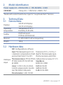
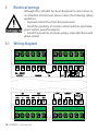
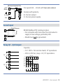
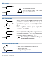
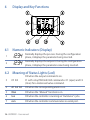
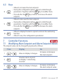
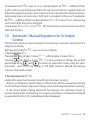
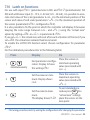
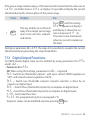
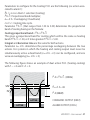
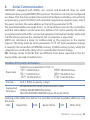
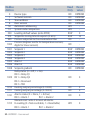
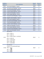
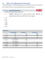
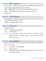
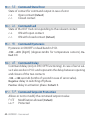
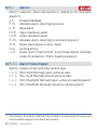
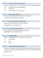
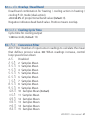
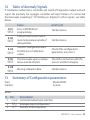
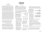
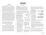
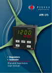
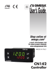
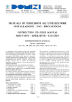
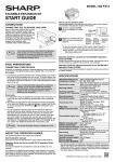
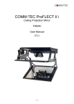
Controller URDR0001 User manual Version 1.0 Summary 1 Safety instructions..................................................................................................................5 1.1 General instructions.....................................................................................................5 1.2 Intended Usage..............................................................................................................5 1.3 Qualified personnel......................................................................................................6 1.4 Remaining hazards.......................................................................................................6 1.5 CE Conformity.................................................................................................................6 2 Model identification...............................................................................................................7 3 Technical Data.........................................................................................................................7 3.1 General data...................................................................................................................7 3.2 Hardware data...............................................................................................................7 3.3 Software data.................................................................................................................8 4 Dimensions and Installation................................................................................................9 5 Electrical wirings.................................................................................................................. 10 5.1 Wiring diagram........................................................................................................... 10 6 Display and Key Functions................................................................................................. 16 6.1 Numeric Indicators (Display)................................................................................... 16 6.2 Meaning of Status Lights (Led)............................................................................... 16 6.3Keys..................................................................................................................................17 17 7 Controller Functions..................................................................................... 7.1Modifying Main Setpoint and Alarm Setpoint Values................................................17 7.2Auto-Tuning................................................................................................................. 18 7.3 Manual Tuning............................................................................................................ 18 7.4 Automatic Tuning....................................................................................................... 18 7.5Soft-Start....................................................................................................................... 18 7.6 Automatic / Manual Regulation for % Output Control.....................................19 7.7 Pre-Programmed Cycle............................................................................................. 20 URDR0001 - User manual - 3 7.8 Programming Modul.......................................................................... 21 7.9 Loading default values............................................................................................. 22 7.10 Latch on functions...................................................................................................... 23 7.11 Loop Break Alarm On Current Transformer......................................................... 24 7.12 Digital Imput Functions............................................................................................ 25 7.13 Dual Action Heating-Cooling................................................................................. 26 8 Serial Communication........................................................................................................ 29 9Configuration........................................................................................................................ 35 9.1 Modify Configuration Parameters......................................................................... 35 10Table of Configuration Parameters................................................................................. 36 54 11 Alarm Intervention Modes.......................................................................... 12 Table of Anomaly Signals................................................................................................... 59 13 Summary of Configuration parameters........................................................................ 59 4 - URDR0001 - User manual Introduction Dear valued Customer! Thank you for purchasing and using a product from our company. The compact universal controller URDR integrates in a single device all options for sensor reading and actuators command, beside extended supply range 24 to 230 Vac/Vdc. Thanks to 18 selectable sensors and outputs configurable as relay, SSR command, 4 to 20 mA and 0 to10 Volt the user can reduce stock needs. The series includes also a model with serial communication RS485 Modbus RTU and with a loading control function via the amperometric transformer. The possibility to repeat parametrization is simplified by the programming module with internal battery that do not require power supply for the controller For getting the highest effort out of this unit, we kindly ask you to follow the below mentioned instructions: Every person who is involved with the installation or usage of this unit, must read carefully and understand the installation manual and safety instructions! 1 Safety instructions 1.1 General instructions To ensure the safe operation of this unit the instructions that appear in this manual must be strictly observed. In addition, when used all applicable legal and safety regulations for the respective application must be observed. The same applies correspondingly to the use of accessories. 1.2 Intended Usage Units from the controller series UR are used for displaying and monitoring of process values. Any other use is regarded not in accordance with the intended usage. Units from the controller series UR are not meant to be used as sole safety means to prevent dangerous situations on machinery and installations. Machinery and intallations must be so designed that fault conditions can not lead to harmful situations to operating personnel (e.g. by independent limit value switches, mechanical locking etc.). URDR0001 - User manual - 5 1.3 Qualified personnel Units from the controller series UR must only be operated in accordance with the technical specifications by qualified personnel. Personnel regarded qualified is familiar with the installation, assembly, putting into operation and operation of the units and possesses adequate professional qualification for the task. 1.4 Remaining hazards Units from the controller series UR are state of the art and safe to operate. A risk of danger can occur when deployed and operated improperly by untrained personnel. In this manual remaining hazards are marked by the following warning symbol: This symbol indicates that non-observance of the safety guidelines may cause hazards to persons even serious injury or death and/or the possibility of property damage. 1.5 CE Conformity The CE certificate is available at our company. We are pleased to send you a copy of it. Please feel free and contact us to get a copy. 6 - URDR0001 - User manual 2 Model identification Power supply 24…230 Vac/Vdc +/- 15% 50/60Hz – 5,5VA URDR0001 2 Relays 5A + 1 SSR/V/mA + RS485 +T.A.* * Model with current transformer input for “Loop Break Alarm” function. 3 Technical Data 3.1 General data Material 4x0.40 inch displays 4x0.30 inch displays Temperature 0-45 °C Humidity 35..95 uR% IP65 front panel IP20 box and terminals PC ABS UL94VO self-exstinguishing Weight 165 g Displays Operating temperature Sealing 3.2 Hardware data AN1 Configurable via software Input Thermocouple type K, S, R, Tolerance (25°C) +/-0.2 % ± 1 J. Automatic compensation of cold digit for thermocouple input, thermo resistance and V/mA. junction from from 0°C to 50°C. Thermoresistance: PT100, PT500, Cold junction accuracy 0.1°C/°C. Analogue Impedance: PT1000, Ni100, PTC1K, NTC10K imput 0-10 V: Ri>110KΩ (β 3435K) 0-20 mA: Ri<5Ω Linear: 0-10V, 0-20 or 4-20mA, 0-40mV, amperometric transfor- 4-20 mA: Ri<5Ω 0-40 mV: Ri>1MΩ mer T.A. 50mA 1024 points Potentiometers: 6 KΩ, 150 KΩ. URDR0001 - User manual - 7 Relay output 2 relays Configurable for command or alarm. Contacts 5A/250V~Resistite loads Configurable: 1 linear 0/4…20mA /SSR/0… - SSR 12V 30mA SSR/V/mA 10Volt - 0-10V (9500 points) Configurable as command or reoutput - 0-20mA (7500 points) transmission of setpoint/process - 4-20mA (6000 points) 3.3 Software data Regulation ON - OFF with hysteresis. algorithms P, P.I., P.I.D., P.D. with proportional time. Proportional band 0...9999 °C or °F Integral time 0,0...999,9 sec. (0 excludes integral function) Derivative time 0,0...999,9 sec. (0 excludes derivative function) Manual or automatic Tuning, configurable alarms, protection of command and alarm setpoints, activation of functions via digital input, preset cycle with Start / Stop. Controller functions 8 - URDR0001 - User manual Dimensions and Installation 72 mm 64 mm 90 mm 4 Extractable terminal blocks Din rail mounting guide EN50022 Memory Card (Optional) with battery URDR0001 - User manual - 9 5 Electrical wirings Although this controller has been designed to resist noises in an industrial environment, please notice the following safety guidelines: • Separate control lines from the power wires. • Avoid the proximity of remote control switches, electromagnetic meters, powerful engines. WARNING • Avoid the proximity of power groups, especially those with phase control. 5.1 Wiring diagram 10 - URDR0001 - User manual Power supply 23 Supply 24 24...230 AC/DC Switching supply with extended range 24…230 Vac/dc ±15% 50/60Hz – 5,5VA (galvanic isolated) AN1 Analogue Imput For thermocouples K, S, R, J. • Comply with polarity. • For possible extensions, use a compensated wire and terminals suitable for the thermocouples used (compensated). • When shielded cable is used, it should be grounded at one side only. Shield 14 13 Shield PT/NI100 15 A 14 B 13 C For thermoresistances PT100, NI100. • For the three-wire connection use wires with the same section. • For the two-wire connection short-circuit terminals 1 and 3. • When shielded cable is used, it should be grounded at one side only. • Select internal jumper JP3 as in the figure. Red/Rosso 15 White/Bianco 14 Red/Rosso 13 Shield 14 PTC/NTC 15 For thermoresistances NTC, PTC, PT500, PT1000 and potentiometers. When shielded cable is used, it should be grounded at one side only to avoid ground loop currents. URDR0001 - User manual - 11 Shield +VDC 16 For linear signals V / mA. • Comply with polarity. • When shielded cable is used, it should be grounded at one side only. 14 V/I + 13 Example of Connection for linear input Volt and mA +12V 16 Max 30mA 0...10V V/A 13 For signals 0….10 V. - V/I + 14 PRESSURE TRANSMITTER +12V 16 C 30 mA 14 B 4...20mA V/A 13 A PRESSURE TRANSMITTER External supply 14 B 4...20mA V/A 13 A 12 - URDR0001 - User manual Comply with polarity. For signals 0/4….20 mA with three-wire sensor. Comply with polarity: A= Sensor output B= Sensor ground C= Sensor power For signals 0/4….20 mA with external power of sensor. Comply with polarity: A= Sensor output B= Sensor ground PRESSURE TRANSMITTER +12V 16 C 30 mA For signals 0/4….20 mA with two-wire sensor. Comply with polarity: A= Sensor output C= Sensor power supply 14 4...20mA V/A 13 A Serial Input Shield/Schermo - 20 RS485 + 21 19 RS485 Modbus RTU communication. • For networks with more than five instruments supply in low voltage, preferably Vdc. • Shield must not be grounded. Relay Q1 - Q2 Output 1 Q1 2 Capacity: • 5 A / 250 V~ for resistive loads, 105 operations. • 20/2 A, 250 Vac, cosφ = 0.3, 105 operations. Life Curve 4 Q2 5 6 Service life (x104 operations) 200 3 100 AC250V DC30 V AC125 V AC125V COS ø=0.4 50 DC30 V t=7ms 20 10 5 0 AC250V COS ø=0.4 DC30 V t=15ms 1 2 3 4 Contact load current (A) 5 URDR0001 - User manual - 13 SSR output 12 SSR/V/mA 11 SSR command 12V/30mA Short-circuit pins 9 and 10 as in the figure to use SSR output 10 Selection 9 mA / Volt output 12 mA OPS 11 8 7 12 V 11 10 Selection 9 Pins 11-12: linear output in mA configurable using parameters as command (Parameter c.out) or retransmission of process or setpoint (Parameter retr.). Pins 7-8: optional external power supply for current loop (max 24Vdc). Linear output in Volt configurable using parameters as command (Parameter c.out) or retransmission of process or setpoint (Parameter retr.). Short-circuit pins 9 and 10 as in the figure to use linear output in Volt. Current Transformer Input 19 TA 18 14 - URDR0001 - User manual • Input 50mA for amperometric transformer • Sampling time 80ms • Configurable by parameters Digital Input 1 I D 15 GND 14 Combined use of digital input and T.A. input Digital input according to parameter dGt.i. This combined use is possible only with sensors TC, 0…10V, 0/4…20mA, 0…40mV. Digital Input 2 I D 17 +12V 16 Use of digital input without T.A. input Digital input according to parameter dGt.i. URDR0001 - User manual - 15 6 Display and Key Functions 6.1 Numeric Indicators (Display) 1 2 1234 1234 Normally displays the process. During the configuration phase, it displays the parameter being inserted. Normally displays the setpoint. During the configuration phase, it displays the parameter value being inserted. 6.2 Meaning of Status Lights (Led) 3 C1 C2 ON when the output command is on. C1 with relay/SSR/mA/Volt command or C1 (open) and C2 (close) for a motorised valve command. 4 A1 A2 A3 ON when the corresponding alarm is on. 5 Man ON when the “Manual” function is on. 6 tun ON when the controller is running an “Autotune” cycle. 7 rem ON when the controller communicates via serial port. 16 - URDR0001 - User manual 6.3 Keys 8 • Allows to increase the main setpoint. • During the configuration phase, allows to slide through parameters. Together with the SET key it modifies them. • Pressed after the SET key it allows to increase the alarm setpoint. 9 • Allows to decrease the main setpoint. • During the configuration phase, allows to slide through parameters. Together with the SET key it modifies them. • Pressed after the SET key it allows to decrease the alarm setpoint. 10 • Allows to display the alarm setpoint and runs the autotuning function. • Allows to vary the configuration parameters. SET 7 Controller Functions 7.1 Modifying Main Setpoint and Alarm Setpoint Values The setpoint value can be changed by keyboard as follows: Press 1 2 3 or Display Do Value on display 2 changes. Increases or decreases the main setpoint. Visualize alarm setpoint on display 1 value being inserted. SET or Value on display 2 changes. Increases or decreases the alarm setpoint value. URDR0001 - User manual - 17 7.2 Auto-Tuning Tuning procedure calculates the controller parameters and can be manual or automatic according to selection on parameter 57 ( tunE). 7.3 Manual Tuning Manual procedure allows the user greater flexibility to decide when to update P.I.D. algorithm work parameters. The procedure can be activated in two ways: • Running Tuning by keyboard: Press SET key until display 1 shows the writing tunE with display 2 showing off, press , display 2 shows on. TUN led switches on and the procedure begins. •Running Tuning by digital input: Select tune on parameter 61 dGt.i. At first activation of digital input (commutation on front panel) TUN led switches on and at second activation switches off. 7.4 Automatic Tuning Automatic tuning activates when the controller is switched on or when the setpoint is modified to a value over 35%. To avoid an overshoot, the treshold where the controller calculates new P.I.D. parameters is determined by the setpoint value minus the “Set Deviation Tune” (see parameter 58 S.D.tu.). To exit Tuning and keep P.I.D. values unchanged, press SET key until display 1 shows the writing tune and display 2 shows on. Press , display 2 shows off. TUN led switches off and procedure finishes. 7.5 Soft-Start To reach the setpoint the controller can follow a gradient expressed in units (example: Degree/Hours). Enter the gradient on parameter 62 GrAd. with chosen Units/Hours; only on subsequent activation the controller uses Soft-Start function. 18 - URDR0001 - User manual If parameter 59 op.mo. is set on cont. and parameter 63 ma.ti. is different from 0, after switch-on and elapsing of the time set on parameter 63, setpoint does not follow the gradient anymore, but it reaches final setpoint with maximum power. Autotuning does not work when Soft-Start is activated: otherwise if parameter 63 ma.ti. is different from 0 and parameter 57 tune is set on auto, Autotuning starts when Soft-Start time is finished. If parameter 57 tune is set on man., the Autotuning can be started only when Soft-Start finishes. 7.6 Automatic / Manual Regulation for % Output Control This function allows to select automatic functioning or manual command of the output percentage. With parameter 60 Au.ma., can select two methods. 1First selection ( en.) Pressing SET key display 1 shows p.---, while display 2 shows Auto. Pressing key display shows Man.; it is now possible to change the output percentage using and . To return to automatic mode, using the same procedure, select Auto on display 2: led MAN switches off and functioning returns to automatic mode. 2Second selection (EN.ST,) enables the same functioning, but with two important variants: • If there is a temporary power failure or after switch-off, the manual functioning as well as the previous output percentage value will be maintained at restarting. • If the sensor breaks during automatic functioning, the controller moves to manual mode while maintaining the output percentage command unchanged as generated by the P.I.D. immediately before breakage. URDR0001 - User manual - 19 7.7 Pre-Programmed Cycle Setpoint The pre-programmed cycle function activates by setting Pr.cy or Pc.SS. on parameter 59 oP.Mo. First selection (Pr.cy): the controller reaches setpoint1 Hold basing on the gradient set on Setpoint 2 Natural cooling parameter 62 Grad., then it Max. power reaches maximum power up to Setpoint 1 setpoint 2. When the process Gradient reaches maximum power, this setpoint is maintained for the time set on parameter 63 ma.ti. Time On expiry, the command output is disabled and controller displays stop. Cycle starts at each activation of the controller, or via digital input if it is enabled for this type of functioning (see parameter 61 dGt.i.). Setpoint Second selection (Pr.cy): start-up is decided only on activation of the digital input, Setpoint 1 Natural cooling according to the setting of Gradient parameter 61 dGt.i. On start-up, controller reaches setpoint 1 following gradient set in parameter 62 Grad. Time When the process reaches this gradient, it is maintained for the time set on parameter 63 ma.ti. On expiry, command output is disabled and the controller displays stop. Hold 20 - URDR0001 - User manual 7.8 Programming Module (optional) Parameters and setpoint values can be duplicated from one controller to another using the Programming Module. 2 modes are available: • With the controller connected to the power supply. Insert memory card when the controller is off. On activation display 1 shows memo and display 2 shows --- (only if the correct values are saved in the Programming Module). By pressing key display 2 shows Load, then confirm using SET key. Controller loads the new value and restarts. RED LIGHT: waiting for programming GREEN LIGHT: done URDR0001 - User manual - 21 • With the controller not connected to power supply. The memory card is equipped with an internal battery with an autonomy of about 1000 uses (2032 button battery, replaceable). Insert the memory card and press the programming buttons. When writing the parameters, led turns red and on completing the procedure it changes to green. It is possible to repeat the procedure without any particular attention. WARNING Updating Programming Module To update the memory card values, follow the procedure described on first mode, setting display 2 to ---- so as not to load the parameters on controller1. Enter configuration and change at least one parameter. Exit configuration. Changes are stored automatically. 7.9 Loading default values This procedure allows to restore factory settings of the instrument. Press 1 2 3 1 SET for 3 seconds o SET to confirm Display Do Display 1 visualizes 0.000 with 1st digit blinking, while display 2 shows PASS. Change blinking digit and move to the next one with SET . Device loads default settings. Enter password: 9999. Turn off and restart the instrument. If on activation the controller does not display memo it means no data have been saved on the Programming module, but it is possible to update values. 22 - URDR0001 - User manual 7.10 Latch on functions For use with input Pot.1 (potentiometer 6 KΩ) and Pot.2 (potentiometer 150 KΩ) and with linear input (0…10 V, 0...40 mV, 0/4…20 mA), it is possible to associate start value of the scale (parameter 6 LoL.i) to the minimum position of the sensor and value of end scale (parameter 7 uP.L.i) to the maximum position of the sensor (parameter 8 Latc. configured as Std.). It is also possible to fix the point in which the controller will display 0 (however keeping the scale range between LoL.i and uP.L.i) using the “virtual zero” option by setting u.OSt. or u.Oin. in parameter 8 Latc. If you set u.Oin. the virtual zero will reset after each activation of the tool; if you set u.OSt. the virtual zero remains fixed once tuned. To enable the LATCH ON function select chosen configuration for parameter LAtc2. For the calibration procedure refer to the following table: Press 1 2 simultaneaously Display Do Place the sensor on Exit parameters configuminimum operating ration. Display 2 shows value (associated with the writing LAtc. LoL.i.). 2 Set the value on minimum. Display shows Low. Place the sensor on maximum operating value (associated with upL.i.). 3 Set the value to maximum. The display shows HiGH. To exit standard procedure press SET . For “virtual zero” settings place the sensor on the zero point. The tuning procedure starts by exiting the configuration after changing the parameter. URDR0001 - User manual - 23 Press 4 SET Display Do Set the virtual zero value. Display shows uirt. NB: For selection of u.0in. the procedure in point 4 should be followed on each reactivation. To exit procedure press SET . Min Max Zero 7.11 Loop Break Alarm On Current Trasformer This function allows to measure load current and to manage an alarm during malfunctioning (with power in short circuit or always off). The current transformer connected to terminals 15 and 16 must be 50 mA (sampling time 80 ms). • Set end scale value of the current transformer in Amperes on parameter 47 t.a. • Set the intervention threshold of the Loop Break Alarm in Amperes on parameter 48 L.b.a.t. • Set the intervention delay time of the Loop Break Alarm on parameter 49 L.b.a.d. • It is possible to associate the alarm with a relay by setting the parameter AL. 1 and AL. 2 as L.b.a. If a remote control switch or SSR remains closed, controller signals the fault by showing L.b.a.c. on display 2 (alternatively with a command setpoint). 24 - URDR0001 - User manual If the power stage remains open, or the load current is lower than the value set on L.b.a.t., controller shows L.b.a.o. on display. It is possible to display the current absorbed during the closure phase of the power stage. Press 1 SET Display Do Press SET until the writing This key enables to scroll on di- am.t.a. appears on display 1 splay 2 the output percentage, and display 2 shows the curauto / man selection, setpoint rent in amperes ( t.a. >0). The value is also maintained and alarms. when no current circulates on the load. Setting on parameter 48 L.b.A.t. the value 0 it is possible to visualize the current absorbed without generating the Loop Break Alarm. 7.12 Digital Imput Functions On URDR model, digital input can be enabled by using parameters 59 op.mo. and 61 dGt.i. • Parameter 59 op.mo. NB: When using this settings, parameter 61 dGt.i. is ignored. 2t.s.: Switch two thresholds setpoint: with open contact URDR regulates on SET1; with closed contact regulates on SET2; 2t.s.i.: Switch two thresholds setpoint: setpoint selection is done by an impulse on digital input; 3t.s.i.: Switch three thresholds setpoint by an impulse on digital input; 4t.s.i: Switch four thresholds setpoint by an impulse on digital input; t.res.: Customized function; p.c.s.s.: Pre-programmed cycle (see paragraph 7.7). Setpoints values can be modified any time pressing SET key. URDR0001 - User manual - 25 • Parameter 61 dGt.i. NB: Settings on this parameter are available only if cont. or pr.cY. are selected on parameter 59 op.mo. st.st.: Start / Stop; operating on digital input the controller switches alternatively from start to stop; rn.n.o.: Run N.O. Controller is in start only with closed input; rn.n.c. : Run N.C. Controller is in start only with open input; L.c.n.o.: With closed input allows to lock the reading of sensors; Lc.n.c.: With open input allows to lock the reading of sensors; tune: Enables / disables Tuning function if parameter 57 tune is selected as man.; a.ma.i.: If parameter 60 au.ma. is selected as en. or en.st. controller switch from automatic to manual functioning; a.ma.c.: If parameter 60 au.ma. is selected as en. or en.st. URDR works in automatic mode if input is open or in manual mode if input is closed. 7.13 Dual Action Heating-Cooling URDR is suitable also for systems requiring a combined heating-cooling action. Command output must be configured as Heating P.I.D. (Act.t. = HEAT and with a P.b. greater than 0), and one of the alarms (AL.1, AL. 2 or AL. 3) must be configured as cooL. Command output must be connected to the actuator responsible for heat, while the alarm will control cooling action. Parameters to configure for the Heating P.I.D. are: Act.t. = HEAT Command output type (Heating); P.b.: Heating proportional band; t.i : Integral time heating and cooling; t.d. : Derivative time heating and cooling; t.c.: Heating time cycle. 26 - URDR0001 - User manual Parameters to configure for the Cooling P.I.D. are the following (ex: action associated to alarm 1): AL.1 = cooL Alarm 1 selection (Cooling); P.b.M.: Proportional band multiplier; ou.d.b.: Overlapping / Dead band; co.t.c.: Cooling time cycle. Parameter p.b.m. (that ranges from 1.00 to 5.00) determines the proportional band of cooling basing on the formula: Cooling proportional band = P.b. x P.b.M. This gives a proportional band for cooling which will be the same as heating band if P.b.M. = 1.00, or 5 times greater if P.b.M. = 5.00. Integral and derivative time are the same for both actions. Parameter ou.d.b. determines the percentage overlapping between the two actions. For systems in which the heating and cooling output must never be simultaneously active a dead band ( ou.d.b. ≤ 0) can be configured, and vice versa an overlapping ( ou.d.b. > 0). The following figure shows an example of dual action P.I.D. (heating-cooling) with t.i. = 0 and t.d. = 0. p.b x p.b.m. (COOL) SPV au.d.b. < 0 PV p.b (HEAT) ACTIVE ACTIVE COMMAND OUTPUT (HEAT) ALARM OUTPUT (COOL) URDR0001 - User manual - 27 p.b x p.b.m. (COOL) SPV au.d.b. = 0 PV p.b (HEAT) ACTIVE ACTIVE COMMAND OUTPUT (HEAT) ALARM OUTPUT (COOL) p.b x p.b.m. (COOL) SPV au.d.b. > 0 p.b (HEAT) PV ACTIVE ACTIVE COMMAND OUTPUT (HEAT) ALARM OUTPUT (COOL) Parameter co.t.c. has the same meaning as the heating time cycle t.c. Parameter coo.f. (cooling fluid) pre-selects the proportional band multiplier P.b.M. and the cooling P.I.D. time cycle co.t.c. basing on the type of cooling fluid: coo.F. Air oiL H2o Cooling fluid type P.b.M. co.t.c 1.00 10 1.25 4 2.50 2 Once selected, parameter coo.f., parameters P.b.M., oud.b. and co.t.c. can however be changed. 28 - URDR0001 - User manual Air Oil Water 8 Serial Communication URDR0001, equipped with RS485, can receive and broadcast data via serial communication using MODBUS RTU protocol. The device can only be configured as a Slave. This function enables the control of multiple controllers connected to a supervisory system (SCADA). Each controller responds to a master query only if the query contains the same address as that in the parameter SL.Ad. The permitted addresses range from 1 to 254 and there must not be controllers with the same address on the same line. Address 255 can be used by the master to communicate with all the connected equipment (broadcast mode), while with 0 all the devices receive the command, but no response is expected. URDR can introduce a delay (in milliseconds) in the response to the master request. This delay must be set on parameter 72 se.de. Each parameter change is saved by the controller on EEPROM memory (100000 writing cycles), while the setpoints are saved with a delay of ten seconds after the last change. NB: changes made to Words that are different from those reported in the following table can lead to malfunction. Modbus RTU protocol features Selection on parameter 70 bd.rt. : 4.8 k 4.800 bit/Sec. 9.6 k 9.600 bit/Sec. 19.2k 19.200 bit/Sec. Baud-rate 28.8k 28.800 bit/Sec. 38.4k 38.400 bit/Sec. 57.6k 57.600 bit/Sec. Format 8, N, 1 (8 bit, no parity, 1 stop) Supported functions WORD READING (max 20 word) (0x03, 0x04) SINGLE WORD WRITING (0x06) MULTIPLE WORDS WRITING (max 20 word) (0x10) Looking at the table here below it is possible to find all available addresses and functions: RO Read Only R/W Read / Write WO Write Only URDR0001 - User manual - 29 Modbus Address 0 1 5 6 50 51 500 510 999 1000 1001 1002 1003 1004 1005 1006 1008 1009 1010 1011 1012 1013 Description Device type Software version Slave address Boot version Automatic addressing System code comparison Loading default values (write 9999) Setpoints storing time in eeprom (0-60 s) Process subjected to the visualization filter Process (degrees.tenths for temperature sensors; digits for linear sensors) Setpoint 1 Setpoint 2 Setpoint 3 Setpoint 4 Alarm 1 Alarm 2 Setpoint gradient Relay status (0 = Off, 1 = On): Bit 0 = Relay Q1 Bit 1 = Relay Q2 Bit 2 = Reserved Bit 3 = SSR Heating output percentage (0-10000) Cooling output percentage (0-10000) Alarms status (0 = None, 1 = Active) Bit 0 = Alarm 1 Bit 1 = Alarm 2 Manual reset: write 0 to reset all alarms. In reading (0 = Not resettable, 1 = Resettable) Bit 0 = Alarm 1 Bit 1 = Alarm 2 30 - URDR0001 - User manual Read Only RO RO RO RO WO WO R/W R/W RO Reset value EEPROM EEPROM EEPROM EEPROM 0 10 - RO - R/W R/W R/W R/W R/W R/W RO EEPROM EEPROM EEPROM EEPROM EEPROM EEPROM EEPROM RO 0 RO RO 0 0 RO 0 WO 0 Modbus Address 1014 1015 1016 1017 1018 1019 1020 1021 1022 Description Error flags Bit 0 = Eeprom writing error Bit 1 = Eeprom reading error Bit 2 = Cold junction error Bit 3 = Process error (sensor) Bit 4 = Generic error Bit 5 = Hardware error Bit 6 = L.B.A.O. error Bit 7 = L.B.A.C. error Bit 8 = Missing calibration data error Cold junction temperature (degrees.tenths) Start / Stop 0 = Controller in STOP 1 = Controller in START Lock conversion ON / OFF 0 = Lock conversion off 1 = Lock conversion on Tuning ON / OFF 0 = Tuning off 1 = Tuning on Automatic / manual selection 0 = Automatic 1 = Manual T.A. current ON (Ampere with tenths) T.A. current OFF (Ampere with tenths) OFF LINE* time (milliseconds) Read Only Reset value RO 0 RO - R/W 0 R/W 0 R/W 0 R/W 0 RO RO R/W - *I f value is 0, the control is disabled. If different from 0, it is the max. time which can elapse between two pollings before the controller goes off-line. If it goes off-line, the controller returns to Stop mode, the control output is disabled but the alarms are active. URDR0001 - User manual - 31 Modbus Address 1023 1024 Description Instant Current (Ampere) Digital Input State Synchronized Tuning for multizone system 0 = Tuning OFF (Normal operating of the regulator) 1 = Output command OFF 1025 2 = Output command ON 3 = Start Tuning 4 = End Tuning and output command OFF (Write 0 for normal operating) Process subjected to the visualization filter and 1099 decimal point selection 1100 Process with decimal point selection 1101 Setpoint 1 with decimal point selection 1102 Setpoint 2 with decimal point selection 1103 Setpoint 3 with decimal point selection 1104 Setpoint 4 with decimal point selection 1105 Alarm 1 with decimal point selection 1106 Alarm 2 with decimal point selection 1108 Gradient Setpoint with decimal point selection 1109 Percentage heating output (0-1000) 1110 Percentage heating output (0-100) 1111 Percentage cooling output (0-1000) 1112 Percentage cooling output (0-100) 2001 Parameter 1 2002 Parameter 2 2072 Parameter 72 3000 Disabling serial control of machine** ** Read Only Reset value R/W 0 R/W R/W 0 0 RO RO R/W R/W R/W R/W R/W R/W RO R/W RO RO RO R/W R/W R/W RO EEPROM EEPROM EEPROM EEPROM EEPROM EEPROM EEPROM 0 0 0 0 EEPROM EEPROM EEPROM 0 By writing 1 on this word, the effects of the writing are cancelled on all the Modbus addresses from 3001 to 3022. Control therefore returns to the controller. 32 - URDR0001 - User manual Modbus Address 3001 3002 3003 3004 3005 3006 3007 3008 3009 3010 3011 3012 3013 3014 3015 3016 3017 3018 Description First word display 1 (ascii) Second word display 1 (ascii) Third word display 1 (ascii) Fourth word display 1 (ascii) Fifth word display 1 (ascii) Sixth word display 1 (ascii) Seventh word display 1 (ascii) Eighth word display 1 (ascii) First word display 2 (ascii) Second word display 2 (ascii) Third word display 2 (ascii) Fourth word display 2 (ascii) Fifth word display 2 (ascii) Sixth word display 2 (ascii) Seventh word display 2 (ascii) Eight word display 2 (ascii) Word LED Bit 0 = LED C1 Bit 1 = LED C2 Bit 2 = LED A1 Bit 3 = LED A2 Bit 4 = LED A3 Bit 5 = LED MAN Bit 6 = LED TUN Bit 7 = LED REM Word keys (write 1 to command keys) Bit 0 = Bit 1 = Bit 2 = SET Read Only Reset value R/W 0 R/W 0 R/W R/W R/W R/W R/W R/W R/W R/W R/W R/W R/W R/W R/W R/W R/W R/W 0 0 0 0 0 0 0 0 0 0 0 0 0 0 0 0 URDR0001 - User manual - 33 Modbus Address Description Word serial relay Bit 0 = Relay Q1 Bit 1 = Relay Q2 3020 Word SSR serial (0 = Off, 1 = On) 3021 Word output 0...10 V serial (0…10000) 3022 Word output 4...20 mA serial (0…10000) Relay state in case of off-line (only if controlled by serial) 3023 Bit 0 = Relay Q1 Bit 1 = Relay Q2 Output state SSR / 0…10 V / 4…20 mA in case of 3024 off-line (only if controlled by serial) (0…10000) Serial process. Setting parameter 54 it is possible 3025 to make averages on the remote process 4001 Parameter 1*** 4002 Parameter 2*** 4072 Parameter 72*** 3019 *** Read Only Reset value R/W 0 R/W R/W R/W 0 0 0 R/W 0 R/W 0 R/W 0 R/W R/W R/W EEPROM EEPROM EEPROM Parameteränderungen in seriellen Adressen 4001 und 4072 werden erst 10 Sekunden nach der letzten Änderung im EEPROM gespeichert. 34 - URDR0001 - User manual 9 Configuration 9.1 Modify Configuration Parameters For configuration parameters see paragraph 10. Press 1 SET for 3 seconds 2 3 or SET to confirm 4 5 or SET or 6 simultaneously Display Do Display 1 shows 0.000 with the 1st digit flashing, while display 2 shows PASS. Changes flashing digit and move to the next one Enter pa sword:1234. using SET key. Display 1 shows the first parameter and display 2 shows the value. Slide up / down through parameters. Enter new data which will be saved on releasing the Increase or decrease displayed value by pressing keys. To change another parameter return to SET and an arrow key. point 4. End of configuration parameter change. The controller exits from programming. URDR0001 - User manual - 35 10 Table of Configuration Parameters The following table includes all parameters. Some of them will not be visible on the models which are not provided with relevant Hardware data. 1 C.out Command Output Command output type selection. c. o1 Default (necessary for using process and setpoint retransmission function with Volt / mA output) c. o2 c.SSr c.uAL. c.4.20 c.0.20 c.0.10 URDR0001 c. o1 c. o2 c.SSr c.uAL. c.4.20 c.0.20 c.0.10 COMMAND Q1 Q2 SSR Q1 (opens) Q2 (closes) 4 ... 20 mA 0 ... 20 mA 0 ... 10 mV 36 - URDR0001 - User manual ALARM 1 Q2 Q1 Q1 ALARM 2 SSR SSR Q2 SSR - Q1 Q1 Q1 Q2 Q2 Q2 2 SEN.Sensor Analogue input configuration/sensor selection Tc.K Tc-K (Default) -260 °C ... 1360 °C Tc.s Tc-S -40 °C ... 1760 °C Tc.r Tc-R -40 °C ... 1760 °C Tc.j Tc-J -200 °C ... 1200 °C Pt Pt100 -200 °C ... 600 °C Pt1 Pt100 -200 °C ... 140 °C ni NI100 -60 °C ... 180 °C ntc NTC10K -40 °C ... 125 °C Ptc PTC1K -50 °C ... 150 °C Pts Pt500 -100 °C ... 600 °C Pt1k Pt1000 -100 °C ... 600 °C 0.10 0 ... 10 Volt 0.20 0 ... 20 mA 4.20 4 ... 20 mA 0.40 0 ... 40 mVolt Pot.1 Potentiometer max 6 Kohm (See paragraph 7.10) Pot.2 Potentiometer max 150 Kohm (See paragraph 7.10) t.A. 50 mA secondary Current transformer 3 d.P. Decimal Point Select type of visualized decimal point 0 Default 0.0 1 Decimal 0.00 2 Decimal 0.000 3 Decimal URDR0001 - User manual - 37 4 Lo.L.S. Lower Limit Setpoint Lower limit selectable for setpoint -999…+9999 [digit3] (degrees.tenths for temperature sensors), Default: 0. 5 up.L.S. Upper Limit Setpoint Upper limit selectable for setpoint -999…+9999 [digit3] (degrees.tenths for temperature sensors), Default: 1750. 6 LoL.i Lower Linear Input Range AN1 lower limit only for linear. Example: with input 4...20 mA this parameter takes value associated to 4 mA -999 bis +9999 [digit3], Default: 0. 7 up.L.i . Upper Linear Input Range AN1 upper limit only for linear. Example: with input 4...20 mA this parameter takes value associated to 20 mA -999 bis +9999 [digit3], Default: 1000. 8 Latc. Latch On Function Automatic setting of limits for linear inputs and potentiometers (see paragraph 7.10) dis. Disabled (Default) std.Standard u.0st. Virtual zero stored u.0in Virtual zero initialized 38 - URDR0001 - User manual 9 o.cAL. Offset Calibration Value added / subtracted to process visualization (usually correcting the value of environment temperature) -999…+1000 [digit3] for linear sensors and potentiometers. -200.0…+100.0 (degrees.tenths for temperature sensors), Default 0.0. 10 G.cAL. Gain Calibration Percentage value that is multiplied for the process value (allows to calibrated the working point) -99.9%…+100.0% (Default = 0.0) 11 Act.t. Action type Regulation type Heat Heating (N.O.) (Default) cooL Cooling (N.C.) H.o.o.S.Lock command above SPV. Example: command output disabled when reaching setpoint, also with P.I.D. value different from 0 12 c. re. Command Reset Type of reset for state of command contact (always automatic in P.I.D. functioning) are. Automatic reset (Default) mre. Manual reset mre.s. Manual reset stored (keeps relay status also after an eventual power failure) URDR0001 - User manual - 39 13 c. S.e. Command State Error State of contact for command output in case of error c.o. Open contact (Default) c.c. Closed contact 14 c. Ld. Command Led State of the OUT1 led corresponding to the relevant contact c.o. ON with open contact c.c. ON with closed contact (Default) 15 c. HY. Command Hysteresis Hysteresis in ON/OFF or dead band in P.I.D. -999…+999 [digit3] (degrees.tenths for temperature sensors), Default 0.0. 16 c. de. Command Delay Command delay (only in ON / OFF functioning). In case of servo valve it also works in P.I.D. and represents the delay between opening and closure of the two contacts -180…+180 seconds (tenths of second in case of servo valve). Negative: delay in switching off phase. Positive: delay in activation phase. Default: 0. 17 c. s.p. Command Setpoint Protection Allows or not to modify the command setpoint value free Modification allowed (Default) LockProtected 40 - URDR0001 - User manual 18 p.b. Proportional Band Proportional band Process inertia in units (ex: if temperature is in °C) 0 ON / OFF t.i. if equal to 0 (Default) 1-9999 [digit 3] (degrees.tenths for temperature sensors) 19t.i . Integral Time Process inertia in seconds 0.0-999.9 seconds (0 = integral disabled), Default: 0. 20 t.d. Derivative Time Normally ¼ of integral time 0.0-999.9 seconds (0 = derivative disabled), Default: 0. Cycle Time 21 t.c. Cycle time (for P.I.D. on remote control switch 10 / 15 sec., for P.I.D. on SSR 1 sec.) or servo time (value declared by servo-motor manufacturer) 1-300 seconds, Default: 10. 22 o.PoL. Output Power Limit Selects max value for command output percentage. 0-100%, Default: 100%. 3 Display of decimal point depends on setting of parameter sen. and parameter d.p. URDR0001 - User manual - 41 23 AL.1 Alarm 1 Alarm 1 selection. Alarm intervention is related to AL1 (See paragraph 11) dis. Disabled (Default) A. AL. Absolute alarm, referring to process b. AL. Band alarm H.d.AL. Upper deviation alarm L.d.AL. Lower deviation alarm A.c.AL. Absolute alarm, referring to command setpoint st.AL. Status alarm (active in Run / Start) cooL Cooling action L.b.A. Status alarm “load control” (Loop Break Alarm). Example: status of contactors / SSR or heating elements 24 A.I.5.o. Alarm 1 State Output Alarm 1 output contact and intervention type n.o. 5. (N.O. start) Normally open, active at start n.c. 5. (N.C. start) Normally closed, active at start n.o. t. (N.O. threshold) Normally open, active on reaching alarm4 n.c. t. (N.C. threshold) Normally closed on reaching alarm4 4 On activation, the output is inhibited if the controller is in alarm mode. Activates only if alarm condition reappers, after that it was restored. 42 - URDR0001 - User manual 25 a1.re. Alarm 1 Reset Alarm 1 contact reset type are. Automatic reset (Default) mre. Manual reset SET mre.s. Manual reset stored. (keeps relay status also after an eventual power failure) 26 a.1.s.e. Alarm 1 State Reset State of contact for alarm 1 output in case of error c.o. Open contact (Default) c.c. Closed contact 27 a.1.Ld. Alarm 1 Led Defines the state of OUT2 led corresponding to the relative contact c.o. ON with open contact c.c. ON with closed contact (Default) 28 a.1.Hy. Alarm 1 Hysteresis -999…+999 [digit 5] (degrees.tenths for temperature sensors), Default: 0.0. 29 a.1.de. Alarm 1 Delay -180…+180 seconds. Negative: delay in alarm output phase. Positive: delay in alarm entry phase. Default: 0. 5 Display of decimal point depends on setting of parameter sen. and parameter d.p. URDR0001 - User manual - 43 30 a.1.sp. Alarm 1 Setpoint Protection Alarm 1 set protection. Does not allow user to modify setpoint free Modification allowed (Default) LockProtected Hide Protected and not visualized 31 AL. 2 Alarm 2 Alarm 2 selection. Alarm intervention is related to AL2. (See paragraph 11) dis. Disabled (Default) A. AL. Absolute alarm, referring to process b. AL. Band alarm H.d.AL. Upper deviation alarm L.d.AL. Lower deviation alarm A.c.AL. Absolute alarm, referring to command setpoint st.AL. Status alarm (active in Run / Start) cooL Cooling action L.b.A. Status alarm “load control” (Loop Break Alarm). Example: status of contactors / SSR or heating elements 32 a.2.so. Alarm 2 State Output Alarm 2 output contact and intervention type n.o. s (N.O. start) Normally open, active at start (Default) n.c. s (N.C. start) Normally closed, active at start n.o. t (N.O. threshold) Normally open, active on reaching alarm6 n.c. t (N.C. threshold) Normally closed, active on reaching alarm 6 6 On activation, the output is inhibited if the controller is in alarm mode. Activates only if alarm condition reappers, after that it was restored. 44 - URDR0001 - User manual 33 A2.re. Alarm 2 Reset Alarm 2 contact reset type Are. Automatic reset (Default) mre. Manual reset (reset / manual reset by keyboard) SET mre.s. Manual reset stored. (keeps relay status also after an eventual power failure) 34 a.2.s.e.Alarm 2 State Error State of contact for alarm 2 output in case of error c.o. Open contact (Default) c.c. Closed contact 35 a.2.Ld. Alarm 2 Led State of OUT2 led corresponding to relative contact c.o. ON with open contact c.c. ON with closed contact (Default) 36 a.2.HY. Alarm 2 Hysteresis -999…+999 [digit7] (degrees.tenths for temperature sensors), Default: 0.0. 37 a.2.d.e.Alarm 2 Delay -180…+180 seconds. Negative: delay in alarm exit phase. Positive: delay in alarm entry phase. Default: 0. 7 Display of decimal point depends on setting of parameter sen. and parameter d.p. URDR0001 - User manual - 45 38a.2.s.p. Alarm 2 Setpoint Protection Alarm 2 set protection. Does not allow operator to change value set free Modification allowed (Default) LockProtected Hide Protected and not visualized 47 t.a. Current Transformer Activation and scale range of current transformer 0 Disabled. 1-200 Ampere. Default: 0 48 L.b.a.t.Loop Break Alarm Threshold Intervention threshold of Loop Break Alarm 0.0-200.0 Ampere. Default: 50.0 49 L.b.a.d.Loop Break Alarm Delay Delay time for Loop break alarm intervention 00.00-60.00 mm.ss. Default: 01.00 50 coo.f. Cooling Fluid Type of refrigerant fluid for heating / cooling P.I.D. Air Air (Default) oiLOil H2oWater 51 p.b.m. Proportional Band Multiplier Proportional band multiplier. Proportional band for cooling action is given by parameter 18 multiplied for this parameter. 1.00-5.00 (Default: 1.00) 46 - URDR0001 - User manual 52 ou.d.b.Overlap / Dead Band Dead band combination for heating / cooling action in heating / cooling P.I.D. mode (dual action). -20.0-50.0% of proportional band value (Default: 0). Negative indicates dead band value. Positive means overlap. 53 co.t.c. Cooling Cycle Time Cycle time for cooling output 1-300 seconds, Default: 10. 54 c.fLt. Conversion Filter ADC Filter: Number of input sensor readings to calculate the mean that defines process value. NB: When readings increase, control loop speed slows down dis.Disabled 2. s.m. 2 Samples Mean 3. s.m. 3 Samples Mean 4. s.m. 4 Samples Mean 5. s.m. 5 Samples Mean 6. s.m. 6 Samples Mean 7. s.m. 7 Samples Mean 8. s.m. 8 Samples Mean 9. s.m. 9 Samples Mean 10.s.m. 10 Samples Mean (Default) 11.s.m. 11 Samples Mean 12.s.m. 12 Samples Mean 13.s.m. 13 Samples Mean 14.s.m. 14 Samples Mean 15.s.m. 15 Samples Mean URDR0001 - User manual - 47 55 c.frn. Conversion Frequency Sampling frequency of analogue / digital converter. NB: Increasing the conversion speed will slow down reading stability (ex: for fast transients, as pressure, it is advisable to increase sampling frequency) 242H. 242 Hz (Maximum speed conversion) 123H. 123 Hz 62 H. 62 Hz 50 H. 50 Hz 39 H. 39 Hz 33.2H. 33.2 Hz 19.6H. 19.6 Hz 16.7H. 16.7 Hz (Default) Ideal for filtering noises 50 / 60 Hz 12.5H. 12.5 Hz 10 H. 10 Hz 8.33H. 8.33 Hz 6.25H. 6.25 Hz 4.17H. 4.17 Hz (Minimum speed conversion) 56 u.FLt. Visualization Filter Slow down the refresh of display, to simplify reading dis. Disabled with pitchfork (maximum speed of display update) Default. fi.or. First order filter with pitchfork 2. s.m. 2 Samples Mean 3. s.m. 3 Samples Mean 4. s.m. 4 Samples Mean 5. s.m. 5 Samples Mean 48 - URDR0001 - User manual 6. s.m. 7. s.m. 8. s.m. 9. s.m. 10.s.m. nuLL f.o. 2 6 Samples Mean 7 Samples Mean 8 Samples Mean 9 Samples Mean 10 Samples Mean (Maximum slow down of display update) Disabled without pitchfork First order filter 57 tuneTune Tuning type selection. (See paragraph 7.2) dis. Disabled (Default) Auto Automatic (P.I.D. parameters are calculated at activation and at change of set point) Man. Manual (launch by keyboard or digital IN) sYnc. Synchronized (see word modbus 1025) 58 s.d.tu.Setpoint Deviation Tune Select the deviation from the command setpoint for the threshold used by autotuning to calculate the P.I.D. parameters 0-5000 [digit10] (degrees.tenths for temperature sensors). Default: 10. 59 op.mo. Operating Mode Select operating mode. (See paragraph 7.12) cont. Controller (Default) pr.cY. Pre-programmed cycle (See paragraph 7.7) 2t.s. Setpoint change by digital input 2t.s.i. Setpoint change by digital input with impulse command 3t.s.i. 3 sets change by digital input with impulse command URDR0001 - User manual - 49 4t.s.i. 4 sets change by digital input with impulse command t.res. Reset time p.c.s.s. Pre-programmed cycle with Start / Stop by digital input 60 au.ma. Automatic / Manual Enable automatic / manual selection. (See paragraph 7.6) dis. Disabled (Default) En.Enabled En.St. Enabled with memory 61 dGt.i . Digital Input Digital input functioning (P59 selection must be cont. or Pr.cY.). (See paragraph 7.12) dis. Disabled (Default: 0) st.st. Pre-programmed cycle with Start / Stop rn.no. Run N.O. (enables regulation with N.O. contact) rn.nc. Run N.C. (enables regulation with N.C. contact) L.c.n.o. Lock conversion N.O. (stop conversion and display value with N.O.) L.c.n.c. Lock conversion N.C. (stop conversion and display value with N.C.) tune Manual Tune (by digital input) a.ma.i. Auto manual impulsive (See paragraph 7.12) a.ma.c Automatic manual contact (See paragraph 7.12) 50 - URDR0001 - User manual 62 Grad.Gradient Rising gradient for Soft-Start or pre-programmed cycle 0 Disabled 1-9999 [Digit/hour8] (degrees/hour with display of tenth for temperature sensor). Default: 0. 63 ma.ti. Maintenance Time Maintenance time for pre-programmed cycle 00.00-24.00 hh.mm. Default: 00.00 64 u.m.c.p.User Menu Cycle Programmed Allows to modify rising gradient and maintenance time, from user menu, when pre-programmed cycle is operating dis. Disabled (Default) Grad.Gradient ma.ti. Maintenance time ALL Both gradient and maintenance time 65 ui.tY. Visualization Type Select visualization for display 1 and 2 1.p.2.s. 1 Process, 2 Setpoint (Default) 1.p.2.H. 1 Process, 2 Hide after 3 sec. 1.s.2.P. 1 Setpoint, 2 Process 1.s.2.H. 1 Setpoint, 2 Hide after 3 sec. 1.p.2.a. 1 Process, 2 Ampere (T.A. input) 1.p2.0 1 Process, 2 Command output percentage 8 Display of decimal point depends on setting of parameter sen. and parameter d.p. URDR0001 - User manual - 51 66 deGr.Degree Select degree type c Centigrade (Default) fFahrenheit 67 retr.Retransmission Retransmission for output 0-10 V or 4…20 mA (short circuit pins 8, 9, 10). Parameters 68 and 69 define the lower and upper limits of the scale. dis.Disabled uo. p. Retransmits process in Volt ma. p. Retransmits process in mA uo. c. Retransmits command setpoint in Volt ma. c. Retransmits command setpoint in mA uo.o.p. Volt output percentage ma.o.p. mA output percentage uo.a.1 Volt alarm 1 setpoint ma.a.1 mA alarm 1 setpoint uo.a.2 Volt alarm 2 setpoint ma.a.2 mA alarm 2 setpoint uo.t.a. Volt T.A. ma.t.a. mA T.A. 68 Lo.L.r. Lower Limit Retransmission Output V / mA retransmission lower limit range -999…+9999 [digit12] (degrees.tenths for temperature sensors), Default: 0. 52 - URDR0001 - User manual 69 up.L.r. Upper Limit Retransmission Output V / mA retransmission upper limit range -999…+9999 [digit9] (degrees.tenths for temperature sensors), Default: 1000. 70 bd.rt. Baud Rate Selects baud rate for serial communication 4.8 k 4.800 Bit/s 9.6 k 9.600 Bit/s 19.2k 19.200 Bit/s (Default) 28.8k 28.800 Bit/s 39.4k 39.400 Bit/s 57.6k 57.600 Bit/s 71 sL.ad. Slave Address Selects slave address for serial communication. 1 – 254, Default: 254 72 se.de. Serial Delay Select serial delay. 0 – 100 milliseconds. Default: 20 73 L.L.o.p. Lower Limit Output Percentage Selects min. value for command output percentage 0 – 100%, Default: 0%. Ex: with c.out selected as 0...10 V and L.L.o.P. set at 10%, command output can change from a min. of 1 V to a max. of 10 V. 9 The display of the decimal point depends on the setting of parameter sen. and the parameter d.p. URDR0001 - User manual - 53 11 Alarm Intervention Modes Absolute Alarm or Threshold Alarm ( a. AL. selection) Pv Alarm Spv Hysteresis parameter > 0 Time On Off On Off On Off On Off Alarm Spv Absolute alarm with controller in heating functioning (par. 11 Act.t. selected Heat) and hysteresis value less than “0” (par. 28 A.1.HY. < 0). Time nb10 Alarm output Time Pv Hysteresis parameter > 0 Alarm Spv On Off nb10 Alarm output Hysteresis parameter < 0 Pv Absolute alarm with controller in heating functioning (par. 11 Act.t. selected Heat) and hysteresis value greater than “0” (par. 28 A.1.HY. > 0). On Off 54 - URDR0001 - User manual Alarm output Absolute alarm with controller in cooling functioning (par. 11 Act.t. selected CooL) and hysteresis value than “0” (par. 28 A.1.HY. > 0). nb10 Time Pv Alarm Spv Hysteresis parameter < 0 On Off nb10 On Off Absolute alarm with controller in cooling functioning (par. 11 Act.t. selected CooL) and hysteresis value less than “0” (par. 28 A.1.HY. < 0). Alarm output Absolute Alarm or Threshold Alarm Referring to Setpoint Command ( a.c.AL. selection) Comand Spv Hysteresis parameter > 0 Alarm Spv Time On Off Off Alarm output Absolute alarm refers to the command set, with the controller in heating functioning (par. 11 Act.t. selected Heat) and hysteresis value greater than “0” (par. 28 A.1.HY. > 0). The command set can be changed by pressing the arrow keys on front panel or using serial port RS485 commands. nb10 URDR0001 - User manual - 55 Band Alarm ( b. AL. selection) Pv Alarm Spv Hysteresis parameter > 0 Comand Spv Time On On Off On Off Off Band alarm hysteresis value greater than “0” (par. 28 A.1.HY. > 0). nb10 Alarm output Hysteresis parameter < 0 Pv Comand Spv Alarm Spv Hysteresis parameter < 0 Band alarm hysteresis value less than “0” (par. 28 A.1.HY. < 0). nb10 Time On On Off On Off 10 Off Alarm output The example refers to alarm 1; the function can also be enabled for alarms 2 and 3 on models that include it. 56 - URDR0001 - User manual Upper Deviation Alarm (H.d.AL. selection) Pv Alarm Spv Hysteresis parameter > 0 Comand Spv Time On Off On Off Upper deviation alarm value of alarm setpoint greater than “0” and hysteresis value greater than “0” (par. 28 A.1.HY. > 0). nb10 Alarm output Pv Comand Spv Alarm Spv Hysteresis parameter > 0 Time On Off On Off Upper deviation alarm value of alarm setpoint less than “0” and hysteresis value greater than “0” (par. 28 A.1.HY. > 0). nb10 Alarm output URDR0001 - User manual - 57 Lower Deviation Alarm (L.d.AL. selection) Pv Comand Spv Hysteresis parameter > 0 Alarm Spv Time On On Off Off Pv nb11 Alarm output Hysteresis parameter > 0 Alarm Spv Comand Spv Time On On Off 11 Lower deviation alarm value of alarm setpoint greater than “0” and hysteresis value greater than “0” (par. 28 A.1.HY. > 0). Off Lower deviation alarm value of alarm setpoint less than “0” and hysteresis value greater than “0” (par. 28 A.1.HY. > 0). nb11 Alarm output a) The example refers to alarm 1; the function can also be enabled for alarms 2 and 3 on models that include it. b) With hysteresis value less than “0” ( A.1.HY. < 0) the broken line moves under the alarm setpoint. 58 - URDR0001 - User manual 12 Table of Anomaly Signals If installation malfunctions, controller will switch off regulation output and will report the anomaly. For example, controller will report failure of a connected thermocouple visualizing e-05 flashing on display for other signals, see table below. E-01 SYS.E E-02 SYS.E E-04 SYS.E E-05 SYS.E E-08 SYS.E 13 Cause what to do Error in EEPROM cell programming. Call Assistance. Cold junction sensor fault or room temperature outside of allowed limits. Call Assistance. Incorrect configuration data. Possible loss of calibration values. Check if the configuration parameters are correct. Thermocouple open or temperature outside of limits. Check the connection with the sensors and their integrity. Missing calibration data. Call Assistance. Summary of Configuration parameters Date: Model URDR: Installer:System: Notes: N. Par. 1 2 3 Description c.oUT Command output type selection sen. Analogue input configuration d.p. Number of decimal points URDR0001 - User manual - 59 N. Par. 4 5 6 7 8 9 10 11 12 13 14 15 16 17 18 19 20 21 22 23 24 25 26 27 28 29 30 31 LoL.s. up.L.s. Lo.L.i. up.L.i. Latc o.cAL. G.cAL. act.t. c. re. c. se. c. Ld. c. Hy. c. de. c. s.p. p.b. t.i. t.d. t.c. o.poL. AL. 1 A.1.s.o. a1.re. a.1.s.e. a.1.Ld. A.1.HY a.1.de. a.1.s.p. aL. 2 Description Lower limit setpoint Upper limit setpoint Lower limit range AN1 only for linear Upper limit range AN1 only for linear Automatic setting of linear input limits Offset calibration Gain calibration Regulation type Command output reset type Contact state for command output in case of error Define the OUT1 led state Hysteresis in ON / OFF or dead band in P.I.D. Command delay Command setpoint protection Proportional band Integral time Derivative time Cycle time Upper limit of heating output percentage Alarm 1 selection Alarm 1 output contact and intervention type Reset type of alarm 1 contact State of contact for alarm 1 output State of OUT2 led Alarm 1 hysteresis Alarm 1 delay Alarm 1 set protection Alarm 2 selection 60 - URDR0001 - User manual N. Par. 32 33 34 35 36 37 38 47 48 49 50 51 52 53 54 55 56 57 58 59 60 61 62 63 64 65 66 67 Description a.2.s.o. Alarm 2 output contact and intervention type a.2.re Reset type of alarm 2 contact a.2.s.e. State of contact for alarm 2 output a.2.Ld. State of OUT2 led A.2.HY. Alarm 2 hysteresis a.2.de. Alarm 2 delay a.2.s.p. Alarm 2 set protection alarm 2 set protection t.a. Activation and scale range of Current transformer L.b.a.t. Intervention threshold of Loop Break Alarm L.b.a.d. Delay time for Loop Break Alarm intervention coo.f. Cooling fluid type p.b.m. Proportional band multiplier ou.d.b. Overlapping / Dead band co.t.c. Cycle time for cooling output c.fLt. Analog converter filter c.Frn. Sampling frequency of analog converter u.fLt. Display filter tune Autotuning type selection s.d.tu. Command setpoint deviation for tuning threshold op.mo Operating mode au.ma. Automatic / manual selection dGt.i. Digital input functioning Grad. Gradient for Soft-Start ma.ti. Cycle maintenance time u.m.c.p. Gradient change and maintenance time by user ui.tY. Display data selection deGr. Degree type selection retr. Retransmission for output 0-10 V or 4…20 mA URDR0001 - User manual - 61 N. Par. Description 68 LoL.r. Lower limit range for linear output 69 up.L.r. Upper limit range for linear output 70 bd.rt. Select baud rate for serial communication 71 sL.ad. Select slave address 72 se.de. Select the serial delay 73 L.L.o.p. Lower limit of heating output percentage Notes / Updates 62 - URDR0001 - User manual URDR0001 - User manual - 63 Wachendorff Prozesstechnik GmbH & Co. KG Industriestrasse 7 • D-65366 Geisenheim Tel.: +49 (0) 67 22 / 99 65 - 20 Fax: +49 (0) 67 22 / 99 65 - 78 E-Mail: [email protected] www.wachendorff-prozesstechnik.de © Copyright by Wachendorff Prozesstechnik GmbH & Co. KG